EP2589475B1 - Procédé et appareil pour la production d'un préimprégné en forme de feuille - Google Patents
Procédé et appareil pour la production d'un préimprégné en forme de feuille Download PDFInfo
- Publication number
- EP2589475B1 EP2589475B1 EP11800879.6A EP11800879A EP2589475B1 EP 2589475 B1 EP2589475 B1 EP 2589475B1 EP 11800879 A EP11800879 A EP 11800879A EP 2589475 B1 EP2589475 B1 EP 2589475B1
- Authority
- EP
- European Patent Office
- Prior art keywords
- tape
- reinforcing fiber
- fiber bundles
- sheet
- die
- Prior art date
- Legal status (The legal status is an assumption and is not a legal conclusion. Google has not performed a legal analysis and makes no representation as to the accuracy of the status listed.)
- Active
Links
- 238000000034 method Methods 0.000 title claims description 33
- 230000008569 process Effects 0.000 title claims description 32
- 239000012783 reinforcing fiber Substances 0.000 claims description 269
- 229920005989 resin Polymers 0.000 claims description 139
- 239000011347 resin Substances 0.000 claims description 139
- 238000005470 impregnation Methods 0.000 claims description 97
- 229920005992 thermoplastic resin Polymers 0.000 claims description 48
- 239000000835 fiber Substances 0.000 claims description 42
- 238000003892 spreading Methods 0.000 claims description 40
- 230000007480 spreading Effects 0.000 claims description 40
- 238000003475 lamination Methods 0.000 claims description 27
- 230000009467 reduction Effects 0.000 claims description 24
- 230000015572 biosynthetic process Effects 0.000 claims description 12
- 229920000049 Carbon (fiber) Polymers 0.000 claims description 9
- 239000004917 carbon fiber Substances 0.000 claims description 9
- 238000010030 laminating Methods 0.000 claims description 9
- 230000001105 regulatory effect Effects 0.000 claims description 8
- 238000003490 calendering Methods 0.000 claims description 7
- 238000005516 engineering process Methods 0.000 description 9
- 238000004519 manufacturing process Methods 0.000 description 9
- 239000003795 chemical substances by application Substances 0.000 description 8
- 238000004513 sizing Methods 0.000 description 7
- 230000000694 effects Effects 0.000 description 6
- -1 etc.) Polymers 0.000 description 6
- VNWKTOKETHGBQD-UHFFFAOYSA-N methane Chemical compound C VNWKTOKETHGBQD-UHFFFAOYSA-N 0.000 description 6
- 239000000047 product Substances 0.000 description 6
- 230000008901 benefit Effects 0.000 description 4
- 239000012467 final product Substances 0.000 description 4
- 238000003825 pressing Methods 0.000 description 4
- 239000004696 Poly ether ether ketone Substances 0.000 description 3
- 239000004697 Polyetherimide Substances 0.000 description 3
- 239000004734 Polyphenylene sulfide Substances 0.000 description 3
- 239000004760 aramid Substances 0.000 description 3
- 229920003235 aromatic polyamide Polymers 0.000 description 3
- 230000006872 improvement Effects 0.000 description 3
- 239000000463 material Substances 0.000 description 3
- 239000011159 matrix material Substances 0.000 description 3
- 229920001652 poly(etherketoneketone) Polymers 0.000 description 3
- 229920002530 polyetherether ketone Polymers 0.000 description 3
- 229920001601 polyetherimide Polymers 0.000 description 3
- 229920000069 polyphenylene sulfide Polymers 0.000 description 3
- 230000003014 reinforcing effect Effects 0.000 description 3
- 229920001169 thermoplastic Polymers 0.000 description 3
- 239000004416 thermosoftening plastic Substances 0.000 description 3
- 229920002292 Nylon 6 Polymers 0.000 description 2
- 229920002302 Nylon 6,6 Polymers 0.000 description 2
- PPBRXRYQALVLMV-UHFFFAOYSA-N Styrene Chemical compound C=CC1=CC=CC=C1 PPBRXRYQALVLMV-UHFFFAOYSA-N 0.000 description 2
- 230000001133 acceleration Effects 0.000 description 2
- 230000000740 bleeding effect Effects 0.000 description 2
- 239000002131 composite material Substances 0.000 description 2
- 238000013329 compounding Methods 0.000 description 2
- 229920001577 copolymer Polymers 0.000 description 2
- 238000010586 diagram Methods 0.000 description 2
- 238000010438 heat treatment Methods 0.000 description 2
- 238000010409 ironing Methods 0.000 description 2
- 239000000155 melt Substances 0.000 description 2
- 229920000728 polyester Polymers 0.000 description 2
- 230000002787 reinforcement Effects 0.000 description 2
- 239000013589 supplement Substances 0.000 description 2
- 238000011144 upstream manufacturing Methods 0.000 description 2
- RNFJDJUURJAICM-UHFFFAOYSA-N 2,2,4,4,6,6-hexaphenoxy-1,3,5-triaza-2$l^{5},4$l^{5},6$l^{5}-triphosphacyclohexa-1,3,5-triene Chemical compound N=1P(OC=2C=CC=CC=2)(OC=2C=CC=CC=2)=NP(OC=2C=CC=CC=2)(OC=2C=CC=CC=2)=NP=1(OC=1C=CC=CC=1)OC1=CC=CC=C1 RNFJDJUURJAICM-UHFFFAOYSA-N 0.000 description 1
- NLHHRLWOUZZQLW-UHFFFAOYSA-N Acrylonitrile Chemical compound C=CC#N NLHHRLWOUZZQLW-UHFFFAOYSA-N 0.000 description 1
- 229920001431 Long-fiber-reinforced thermoplastic Polymers 0.000 description 1
- 239000004677 Nylon Substances 0.000 description 1
- 239000004962 Polyamide-imide Substances 0.000 description 1
- 239000004695 Polyether sulfone Substances 0.000 description 1
- 239000004698 Polyethylene Substances 0.000 description 1
- 239000004642 Polyimide Substances 0.000 description 1
- 239000004721 Polyphenylene oxide Substances 0.000 description 1
- 239000004743 Polypropylene Substances 0.000 description 1
- 239000004793 Polystyrene Substances 0.000 description 1
- 239000002250 absorbent Substances 0.000 description 1
- 230000002745 absorbent Effects 0.000 description 1
- 229920000122 acrylonitrile butadiene styrene Polymers 0.000 description 1
- 239000004676 acrylonitrile butadiene styrene Substances 0.000 description 1
- 230000001070 adhesive effect Effects 0.000 description 1
- 239000003963 antioxidant agent Substances 0.000 description 1
- 230000003078 antioxidant effect Effects 0.000 description 1
- 229920006231 aramid fiber Polymers 0.000 description 1
- 238000009412 basement excavation Methods 0.000 description 1
- 230000015556 catabolic process Effects 0.000 description 1
- 239000003086 colorant Substances 0.000 description 1
- 239000011231 conductive filler Substances 0.000 description 1
- 230000001276 controlling effect Effects 0.000 description 1
- 238000006731 degradation reaction Methods 0.000 description 1
- 230000002708 enhancing effect Effects 0.000 description 1
- 230000001747 exhibiting effect Effects 0.000 description 1
- 239000003063 flame retardant Substances 0.000 description 1
- 239000003365 glass fiber Substances 0.000 description 1
- 238000004898 kneading Methods 0.000 description 1
- 239000007788 liquid Substances 0.000 description 1
- 239000000314 lubricant Substances 0.000 description 1
- 239000000203 mixture Substances 0.000 description 1
- 229920001778 nylon Polymers 0.000 description 1
- 230000003647 oxidation Effects 0.000 description 1
- 238000007254 oxidation reaction Methods 0.000 description 1
- 230000035699 permeability Effects 0.000 description 1
- 239000004014 plasticizer Substances 0.000 description 1
- 229920002492 poly(sulfone) Polymers 0.000 description 1
- 229920002312 polyamide-imide Polymers 0.000 description 1
- 229920001707 polybutylene terephthalate Polymers 0.000 description 1
- 239000004417 polycarbonate Substances 0.000 description 1
- 229920000515 polycarbonate Polymers 0.000 description 1
- 229920006393 polyether sulfone Polymers 0.000 description 1
- 229920000573 polyethylene Polymers 0.000 description 1
- 229920000139 polyethylene terephthalate Polymers 0.000 description 1
- 239000005020 polyethylene terephthalate Substances 0.000 description 1
- 229920001721 polyimide Polymers 0.000 description 1
- 229920001470 polyketone Polymers 0.000 description 1
- 229920000098 polyolefin Polymers 0.000 description 1
- 229920006380 polyphenylene oxide Polymers 0.000 description 1
- 229920001155 polypropylene Polymers 0.000 description 1
- 229920002223 polystyrene Polymers 0.000 description 1
- 238000004904 shortening Methods 0.000 description 1
- 239000003017 thermal stabilizer Substances 0.000 description 1
- 238000002411 thermogravimetry Methods 0.000 description 1
Images


Classifications
-
- B—PERFORMING OPERATIONS; TRANSPORTING
- B29—WORKING OF PLASTICS; WORKING OF SUBSTANCES IN A PLASTIC STATE IN GENERAL
- B29C—SHAPING OR JOINING OF PLASTICS; SHAPING OF MATERIAL IN A PLASTIC STATE, NOT OTHERWISE PROVIDED FOR; AFTER-TREATMENT OF THE SHAPED PRODUCTS, e.g. REPAIRING
- B29C70/00—Shaping composites, i.e. plastics material comprising reinforcements, fillers or preformed parts, e.g. inserts
- B29C70/04—Shaping composites, i.e. plastics material comprising reinforcements, fillers or preformed parts, e.g. inserts comprising reinforcements only, e.g. self-reinforcing plastics
- B29C70/28—Shaping operations therefor
- B29C70/40—Shaping or impregnating by compression not applied
- B29C70/50—Shaping or impregnating by compression not applied for producing articles of indefinite length, e.g. prepregs, sheet moulding compounds [SMC] or cross moulding compounds [XMC]
-
- B—PERFORMING OPERATIONS; TRANSPORTING
- B29—WORKING OF PLASTICS; WORKING OF SUBSTANCES IN A PLASTIC STATE IN GENERAL
- B29B—PREPARATION OR PRETREATMENT OF THE MATERIAL TO BE SHAPED; MAKING GRANULES OR PREFORMS; RECOVERY OF PLASTICS OR OTHER CONSTITUENTS OF WASTE MATERIAL CONTAINING PLASTICS
- B29B15/00—Pretreatment of the material to be shaped, not covered by groups B29B7/00 - B29B13/00
- B29B15/08—Pretreatment of the material to be shaped, not covered by groups B29B7/00 - B29B13/00 of reinforcements or fillers
- B29B15/10—Coating or impregnating independently of the moulding or shaping step
- B29B15/12—Coating or impregnating independently of the moulding or shaping step of reinforcements of indefinite length
- B29B15/122—Coating or impregnating independently of the moulding or shaping step of reinforcements of indefinite length with a matrix in liquid form, e.g. as melt, solution or latex
- B29B15/125—Coating or impregnating independently of the moulding or shaping step of reinforcements of indefinite length with a matrix in liquid form, e.g. as melt, solution or latex by dipping
-
- C—CHEMISTRY; METALLURGY
- C08—ORGANIC MACROMOLECULAR COMPOUNDS; THEIR PREPARATION OR CHEMICAL WORKING-UP; COMPOSITIONS BASED THEREON
- C08J—WORKING-UP; GENERAL PROCESSES OF COMPOUNDING; AFTER-TREATMENT NOT COVERED BY SUBCLASSES C08B, C08C, C08F, C08G or C08H
- C08J5/00—Manufacture of articles or shaped materials containing macromolecular substances
- C08J5/24—Impregnating materials with prepolymers which can be polymerised in situ, e.g. manufacture of prepregs
- C08J5/241—Impregnating materials with prepolymers which can be polymerised in situ, e.g. manufacture of prepregs using inorganic fibres
- C08J5/243—Impregnating materials with prepolymers which can be polymerised in situ, e.g. manufacture of prepregs using inorganic fibres using carbon fibres
-
- B—PERFORMING OPERATIONS; TRANSPORTING
- B29—WORKING OF PLASTICS; WORKING OF SUBSTANCES IN A PLASTIC STATE IN GENERAL
- B29K—INDEXING SCHEME ASSOCIATED WITH SUBCLASSES B29B, B29C OR B29D, RELATING TO MOULDING MATERIALS OR TO MATERIALS FOR MOULDS, REINFORCEMENTS, FILLERS OR PREFORMED PARTS, e.g. INSERTS
- B29K2105/00—Condition, form or state of moulded material or of the material to be shaped
- B29K2105/06—Condition, form or state of moulded material or of the material to be shaped containing reinforcements, fillers or inserts
- B29K2105/08—Condition, form or state of moulded material or of the material to be shaped containing reinforcements, fillers or inserts of continuous length, e.g. cords, rovings, mats, fabrics, strands or yarns
- B29K2105/0872—Prepregs
Definitions
- the present invention relates to process and apparatus for producing a sheet-shaped prepreg, and specifically, to process and apparatus for producing a sheet-shaped prepreg using continuous reinforcing fibers, into which a resin is extremely uniformly impregnated.
- a sheet-shaped prepreg wherein a molten matrix resin is impregnated into reinforcing fibers arranged in a sheet-like form and the resin is maintained at a semicured condition, is utilized broadly in various fields for reinforcing a component, forming a surface, etc. Further, in order to obtain excellent reinforcement advantage, etc., continuous fibers are frequently used as reinforcing fibers, and in particular, a prepreg, in which continuous reinforcing fibers are arranged in a tape-like form, for example, in one direction, and a resin is impregnated thereinto, is preferably employed (for example, Patent document 1).
- a molten resin is impregnated into rovings (each having a circular or elliptical cross section) comprising long fibers for reinforcing fibers
- rovings each having a circular or elliptical cross section
- Patent document 2 a technology wherein the molten resin impregnating ability into portions between long fibers is improved by spreading each roving
- Patent document 3 a technology wherein the molten resin impregnating ability into portions between long fibers is improved by sucking present air between long fibers forming the roving.
- the rovings are drawn into a die after dividing them one by one.
- Patent document 5 in order to control the cross-sectional shape and gain a flat plane of an obtained sheet-shaped prepreg, known is a technology wherein using a pair of vertically arranged convexo-concave rolls (calender rolls) (for example, Patent document 5).
- this technology however, only widening by convexo-concave rolls is disclosed, and a necessary factor for the strict control of the constant sheet width, with respect to narrowing after widening in width, is not disclosed at all, and therefore, it is not a satisfactory technical content.
- Patent document 6 teaches the manufacture of a long fiber tape and to reduce process troubles caused by fluff when a fiber-reinforced thermoplastic resin tape is manufactured.
- thermoplastic resin tape manufacturing apparatus which is provided with a thermoplastic resin-impregnation machine having a plurality of opening bars opening carbon fiber bundles, fluff suction devices each set in the rear step of the opening bar, and impregnation heads each set in the rear step of the fluff suction device having a plurality of slide bars inside and a takeup roller which is set in the rear step of the thermoplastic resin-impregnation machine.
- the fluff produced by the opening operation of the apparatus is sucked by the fluff suction devices to be removed.
- Patent document 7 relates to the manufacture of long fiber-reinforced thermoplastic composite material which exhibits good impregnation state of resin into the fibers.
- an object of the present invention is to provide process and apparatus for producing a sheet-shaped prepreg which, in particular, with respect to a sheet-shaped prepreg prepared by impregnating a molten resin into tape-like reinforcing fiber bundles each comprising a plurality of continuous reinforcing fibers, even in case where a thermoplastic resin having a relatively high melt viscosity is used, can impregnate the resin uniformly and satisfactorily all over through the predetermined thickness, and which can considerably shorten the time required for resin impregnation, thereby can produce a high-grade sheet-shaped prepreg at a high productivity.
- a process according to claim 1 for producing a sheet-shaped prepreg according to the present invention comprises the following steps of:
- the tape-like reinforcing fiber bundle comprising continuous reinforcing fibers is spread and widened at one or both of stages before and after the introduction into the die, using means of spreading such as air, ironing or vibration at the stage before the introduction and using means of spreading such as ironing at the stage after the introduction, and whereby the thickness of each tape-like reinforcing fiber bundle is reduced.
- the thickness is reduced to be capable of impregnating the resin sufficiently and satisfactorily in a short period of time.
- each tape-like reinforcing fiber bundle is formed as a sheet-like material small in thickness, the molten resin is easily impregnated into each tape-like reinforcing fiber bundle for the small distance in the thickness direction (impregnation distance), and therefore, a uniform impregnation is performed all through the desired thickness direction in a short period of time.
- the prepreg since the time required for resin impregnation for each tape-like reinforcing fiber bundle may be short, the prepreg can be prepared in a short time only summing up the time required for the resin impregnation and the time required for the lamination successively performed in the same die, the productivity can be remarkably enhanced from the viewpoint of the time for production.
- the arrangement of the reinforcing fibers in the prepreg can be kept in a uniform and good condition, since the thickness of the tape-like reinforcing fiber bundle can be easily uniformed at the stage of spreading and widening of each tape-like reinforcing fiber bundle, in particular, the thickness of the tape-like reinforcing fiber bundle can be easily uniformed at the stage of spreading and widening of each tape-like reinforcing fiber bundle before resin impregnation, and the continuous reinforcing fibers can also be easily arranged uniformly.
- the molten resin has been uniformly impregnated into the respective tape-like reinforcing fiber bundles laminated as described above, the obtained sheet-like prepreg becomes a high-grade one which has uniform properties all over through.
- thermoplastic resin is used for the above-mentioned molten resin. Namely, as described above, because the present invention is more effective to a resin with high melt viscosity than to a resin with low melt viscosity, it is particularly effective for the case using a thermoplastic resin.
- thermoplastic resin used is not particularly limited, such as polyamide (nylon 6, nylon 66, aromatic polyamide, etc.), polyolefin (polyethylene, polypropylene, etc.) polyester (polyethylene terephthalate, polybutylene terephthalate, etc.), polycarbonate, polyamideimide, polyphenylene sulfide, polyphenylene oxide, polysulfone, polyethersulfone, polyetheretherketone, polyetherketoneketone, polyketone, polyimide, polyetherimide, polystyrene, ABS, liquid crystalline polyester, and copolymer of acrylonitrile and styrene, etc. can be used. A mixture thereof may be used.
- a copolymer such as a copolymerized nylon of nylon 6 and nylon 66 may be used.
- a copolymer such as a copolymerized nylon of nylon 6 and nylon 66 may be used.
- polyphenylene sulfide, polyetheretherketone, polyetherketoneketone, polyetherimide or aromatic polyamide is a preferable embodiment in the present invention, because of the enhanced necessity for using continuous reinforcing fibers that exhibit an excellent reinforcement effect.
- flame retardant, weather resistance improvement agent, and the other antioxidant, thermal stabilizer, ultraviolet absorbent, plasticizer, lubricant, colorant, compatibilizer, conductive filler, etc. may be added according to required properties of the molded product to be obtained.
- the kinds of the above-described continuous reinforcing fiber is also not particularly limited, any reinforcing fibers such as carbon fiber, glass fiber or aramid fiber can be used, and a hybrid structure combining these fibers can also be employed.
- carbon fiber is preferred to use.
- use of carbon fiber having a high strength which hardly generate fuzz in the fiber bundle thickness reduction step or the resin impregnation step is further preferred. In concrete terms, it indicates carbon fibers having tensile strength of 4,500 MPa or more, and further, 5,000 MPa or more.
- a sizing agent provided to the reinforcing fibers, use of one having 5% or less thermal reduction at 300°C is preferred. More preferably, sizing agent having 15% or less thermal reduction at 350°C.
- a sizing agent which hardly thermally decompose fuzz are hardly generated in the fiber bundle thickness reduction step or the resin impregnation step, and gas generation in the die can be minimized, and the advantages according to the present invention can be exhibited to the maximum.
- Such advantages can be remarkably exhibited particularly in a heat-resistant thermoplastic resin which processing temperature is around 300°C or higher (for example, polyphenylene sulfide, polyetheretherketone, polyetherketoneketone, polyetherimide or aromatic polyamide).
- the above-described thermal reduction means a rate of reduction of a sizing agent at each temperature of 300°C and 350°C when heated under an atmospheric condition from 25°C to 400°C at a temperature elevation speed of 10°C/min. in thermo-gravimetric analysis.
- the above-described tape-like reinforcing fiber bundles arranged in the multilayer form can be disposed at a formation of a plurality of steps, in which a gap is given between adjacent tape-like reinforcing fiber bundles, in the thickness direction of each tape-like reinforcing fiber bundles, at one or both of stages before and after the introduction into the die.
- the molten resin is impregnated at a condition where an adequate gap is provided between the respective tape-like reinforcing fiber bundles disposed at a formation of a plurality of steps, the molten resin is impregnated more easily into each tape-like reinforcing fiber bundle from the both surface sides by a small distance (impregnation distance) in the thickness direction. Therefore, a desired uniform impregnation is completed in a shorter period of time, and the productivity is further improved.
- each of the above-described tape-like reinforcing fiber bundles arranged in the multilayer form can be formed by adjoining smaller-width tape-like reinforcing fiber bundles to one another in a width direction of each smaller-width tape-like reinforcing fiber bundle.
- the width of the sheet-shaped prepreg to be produced is greater than a width of each of a tape-like reinforcing fiber bundle which is usually prepared, such a manner can be employed.
- a plurality of smaller-width tape-like reinforcing fiber bundles are adjoined to one another until becoming a predetermined width in a width direction (that is, until substantially becoming a width of a sheet-shaped prepreg to be produced), and after they are formed as a formation of a tape-like reinforcing fiber bundle with a predetermined wide width, the resin can be impregnated into the wide-width tape-like reinforcing fiber bundle.
- a sheet-shaped prepreg having a wide width can be produced easily and efficiently.
- a gap can be given in the width direction between the adjacent smaller-width tape-like reinforcing fiber bundles.
- a seal section capable of reducing the pressure of chamber of passageway to predetermined vacuum degree is connected to a portion directly upstream relative to the fiber bundle introduction step above-described, and a degas step is provided wherein a pressure reduction degree in each of the tape-like reinforcing fiber bundles arranged in the multilayer form is enhanced by passing each of the tape-like reinforcing fiber bundles arranged in the multilayer form through the chamber of the passageway reduced in pressure at the predetermined vacuum degree.
- the amount of air carried into the die by the tape-like reinforcing fiber bundles can be minimized, and it becomes possible to maintain the molten resin impregnation performance into the tape-like reinforcing fiber bundles at a good condition.
- positions for widening tape-like reinforcing fiber bundles adjacent to each other among the tape-like reinforcing fiber bundles arranged in the multilayer form by means of spreading may be shifted to each other in a running direction of the tape-like reinforcing fiber bundles.
- respective fiber bundle thickness reduction means easily at desired positions without interference with each other, and a desired operation can be carried out more securely for each tape-like reinforcing fiber bundle which is one of the targets of thickness reduction and widening.
- a manner can also be employed wherein a plurality of tape-like reinforcing fiber bundles being impregnated with the molten thermoplastic resin or/and having been impregnated with the molten thermoplastic resin are laminated in order at positions shifted in order in the running direction of the tape-like reinforcing fiber bundles.
- a lamination in order it becomes possible to laminate the respective layers more surely and accurately, and improvement of the dimensional accuracy of the sheet-shaped prepreg as a laminate becomes possible.
- a manner can also be employed wherein respective tape-like reinforcing fiber bundles are spread in order or/and respective tape-like reinforcing fiber bundles having been impregnated with the molten thermoplastic resin are laminated in order, using a plurality of fixed guides (for example, squeeze bars) arranged in a running direction of the tape-like reinforcing fiber bundles, and a tunnel for tape-like reinforcing fiber bundles is provided to each of at least a part of the plurality of fixed guides used for the spreading or/and the lamination and at least a part of tape-like reinforcing fiber bundles are run through the tunnels.
- a plurality of fixed guides for example, squeeze bars
- a manner can also be employed wherein impregnation or completion of impregnation of the molten thermoplastic resin into respective tape-like reinforcing fiber bundles is performed at a same position in a running direction of the tape-like reinforcing fiber bundles.
- the tape-like reinforcing fiber bundles arranged in a multilayer form can be impregnated with resin substantially simultaneously at a same position in the running direction. In such a manner, it may become possible to shorten the length of the die.
- the process for producing a sheet-shaped prepreg according to the present invention in the above-described resin impregnation step or lamination step, it is preferred to ventilate gas and/or resin in the die from a degas vent and/or a resin bleed vent equipped to the die.
- a degas vent and/or a resin bleed vent equipped to the die.
- gas generated inside and air carried in by the tape-like reinforcing fiber bundles and the like are ventilated from the degas vent.
- a post-impregnation step can be provided wherein, after the prepreg laminated in the above-described die and formed as a sheet-like shape as its whole shape is pulled from the die, it is further passed through calender rolls.
- calendering treatment by the calender rolls, post-impregnation of the resin becomes possible by pressing between the calender rolls and it becomes possible to achieve a further satisfactory resin impregnated state, and because thickness adjustment by a small amount is possible, it becomes possible to make the thickness of a prepreg as a final product more precisely.
- the above-described calender rolls comprise at least a first calender roll and a second calender roll, at least the second calender roll is a roll with a groove, and after the prepreg formed as a sheet-like shape is widened by passing it through the first calender roll, a width of the sheet-shaped prepreg is regulated so as to become a predetermined width in a width direction while narrowing in width the widened sheet-shaped prepreg, by passing it through the second calender roll.
- the width of the sheet-shaped prepreg can be regulated so as to become a predetermined width while it is narrowed in width, and therefore, it becomes possible to make also the width of a prepreg as a final product more precisely.
- An apparatus for producing a sheet-shaped prepreg according to the present invention wherein a prepreg having a sheet-like shape as its whole shape is produced, and the apparatus comprises:
- the kind of the thermoplastic resin used is not particularly limited, and thermoplastic resins similar to those aforementioned can be used.
- the kind of the above-described continuous reinforcing fibers also is not particularly limited, reinforcing fibers similar to those aforementioned can be used, and in particular, in case where the mechanical properties of a final molded product such as strength are desired to be increased, use of carbon fibers is preferred.
- sizing agents similar to those aforementioned can be used.
- an apparatus can be additionally employed wherein provided is means for disposing the above-described tape-like reinforcing fiber bundles arranged in the multilayer form at a formation of a plurality of steps, in which a gap is given between adjacent tape-like reinforcing fiber bundles, in the thickness direction of each tape-like reinforcing fiber bundle at one or both of stages before and after the introduction into the die.
- an apparatus can be additionally employed wherein the above-described each of the tape-like reinforcing fiber bundles arranged in the multilayer form is formed by adjoining smaller-width tape-like reinforcing fiber bundles to one another in a width direction of each smaller-width tape-like reinforcing fiber bundle. Further, in case where the above-described smaller-width tape-like reinforcing fiber bundles are adjoined to one another to form a predetermined large-width tape-like reinforcing fiber bundle, in the fiber introduction step for introduction into the die, a gap can be given between the adjacent smaller-width tape-like reinforcing fiber bundles in the width direction of the large-width tape-like reinforcing fiber bundle.
- an apparatus can also be additionally employed wherein a seal section capable of reducing in pressure a chamber of a passageway at a predetermined vacuum degree is connected to a portion immediately upstream relative to the fiber bundle introduction means, and a degas means is provided for enhancing a pressure reduction degree in each of the tape-like reinforcing fiber bundles arranged in the multilayer form by passing each of the tape-like reinforcing fiber bundles arranged in the multilayer form through the chamber of the passageway reduced in pressure at the predetermined vacuum degree.
- an apparatus can be additionally employed wherein, in the above-described fiber bundle thickness reduction means, positions for widening tape-like reinforcing fiber bundles adjacent to each other among the tape-like reinforcing fiber bundles arranged in the multilayer form by means of spreading are shifted to each other in a running direction of the tape-like reinforcing fiber bundles.
- an apparatus can also be additionally employed wherein, in the above-described resin impregnation means, positions for impregnation or completion of impregnation of the molten thermoplastic resin into respective tape-like reinforcing fiber bundles are shifted in order in a running direction of the tape-like reinforcing fiber bundles.
- the lamination means comprises means for laminating a plurality of tape-like reinforcing fiber bundles being impregnated with the molten thermoplastic resin or/and having been impregnated with the molten thermoplastic resin in order at positions shifted in order in the running direction of the tape-like reinforcing fiber bundles.
- an apparatus can be additionally employed wherein a plurality of fixed guides (for example, squeeze bars) are arranged in the above-described die in a running direction of the tape-like reinforcing fiber bundles, the fixed guides being used for spreading respective tape-like reinforcing fiber bundles in order or/and laminating respective tape-like reinforcing fiber bundles having been impregnated with the molten thermoplastic resin in order, and tunnels for tape-like reinforcing fiber bundles capable of running at least a part of tape-like reinforcing fiber bundles through the tunnel is provided to each of at least a part of the plurality of fixed guides.
- a plurality of fixed guides for example, squeeze bars
- an apparatus can also be additionally employed wherein the above-described resin impregnation means comprises means for performing impregnation or completion of impregnation of the molten thermoplastic resin into respective tape-like reinforcing fiber bundles at a same position in a running direction of the tape-like reinforcing fiber bundles.
- the lamination means comprises means for laminating a plurality of tape-like reinforcing fiber bundles being impregnated with the molten thermoplastic resin or/and having been impregnated with the molten thermoplastic resin simultaneously at a predetermined position in the running direction of the tape-like reinforcing fiber bundles.
- an apparatus can be additionally employed wherein a degas vent and/or a resin bleed vent is equipped to the above-described die.
- an apparatus can be additionally employed wherein a post-impregnation means is provided which is disposed at a position downstream relative to the die and which has calender rolls performing calendering treatment for the prepreg laminated in the die, formed as a sheet-like shape as its whole shape and pulled from the die.
- an apparatus can be additionally employed wherein the calender rolls comprise, at least, a first calender roll for widening the prepreg formed as a sheet-like shape so as to become a predetermined width in a width direction and a second calender roll with a groove disposed at a position downstream relative to the first calender roll for regulating the widened sheet-shaped prepreg so as to become a predetermined width in a width direction while narrowing in width the widened sheet-shaped prepreg.
- the calender rolls comprise, at least, a first calender roll for widening the prepreg formed as a sheet-like shape so as to become a predetermined width in a width direction and a second calender roll with a groove disposed at a position downstream relative to the first calender roll for regulating the widened sheet-shaped prepreg so as to become a predetermined width in a width direction while narrowing in width the widened sheet-shaped prepreg.
- a high-grade sheet-shaped thermoplastic prepreg in which the resin has been uniformly and satisfactorily impregnated throughout the predetermined thickness and the reinforcing fibers also have been uniformly arranged, can be provided. Further, the time required for resin impregnation can be considerably shortened, and this high-quality sheet-shaped prepreg can be produced with a high productivity.
- Fig. 1 shows a process and an apparatus for producing a sheet shaped prepreg according to an embodiment of the present invention
- symbol 100 indicates the whole of the apparatus for producing a sheet shaped prepreg.
- a fiber bundle introduction step (a fiber bundle introduction means) 1
- a fiber bundle thickness reduction step (a fiber bundle thickness reduction means) 2
- a degas step (a degas means) 3
- a resin impregnation step (a resin impregnation means) 4
- lamination step a lamination means
- a post-impregnation step a post-impregnation means 5
- a plurality of reinforcing fiber bundles (tape-like reinforcing fiber bundles) 10, each comprising a plurality of continuous reinforcing fibers 30, are pulled out from respective creels 11, and sent to a spreader 12 provided as an embodiment of a fiber bundle thickness reduction means for reducing the thickness of each fiber bundle by widening due to spreading.
- the spreader 12 may be one having an oven and accompanying heating as shown in the figure, and alternatively, may comprise directly heating spreading rolls 13.
- the respective tape-like reinforcing fiber bundles 10 having been introduced are spread by a plurality of spreading rolls 13, etc. (or bars for spreading), they are widened by means of the spreading and the thickness of each tape-like reinforcing fiber bundle 10 is reduced.
- an initial thickness T of the tape-like reinforcing fiber bundle 10 comprising the continuous reinforcing fibers 30 is reduced down to a thickness t by spreading and widening to achieve a formation of a thin widened tape-like reinforcing fiber bundle 31.
- tape-like reinforcing fiber bundles may be adjoined in the width direction by a necessary number at the stage of the tape-like reinforcing fiber bundle 10 or at the stage of tape-like reinforcing fiber bundle 31.
- a plurality of tape-like reinforcing fiber bundles 10 having been run in parallel are widened by spreading rolls 13 at positions different from one another shifted in the running direction of the tape-like reinforcing fiber bundles 10, the plurality of widened tape-like reinforcing fiber bundles 10 are adjoined in the width direction to form the widened tape-like reinforcing fiber bundle 31 having a predetermined width and greater in width.
- the tape-like reinforcing fiber bundles 31 each having been reduced in thickness by spreading and widening are introduced into a die 19 for resin impregnation, in this embodiment, after passing through the degas step 3 as shown in Fig. 1 , more concretely, via a vacuum seal means 15 as a degas means.
- vacuum seal means 15 for example, a passageway 16, sealed from outside as much as possible and capable of passing with tape-like reinforcing fiber bundles 31, is formed, and air is sucked from a chamber in the formed the passageway 16 by a vacuum pump (in the example shown in the figure, two vacuum pumps 17, 18).
- the inside of the die 19 for resin impregnation is preferably filled with the molten resin with mixed air and gas as less as possible, and if the tape-like reinforcing fiber bundles 31 carry a large amount of air into the die, because the direct contact between the molten resin and the tape-like reinforcing fiber bundles is damaged, and such a condition is not preferred.
- the amount of air carried in becomes greater as the production speed becomes higher, and it makes resin impregnation more difficult. By such a degas, the amount of air, which the tape-like reinforcing fiber bundles 31 carry into the die, can be minimized, the resin impregnation is facilitated, and the effect according to the present invention can be exhibited as much as possible.
- a molten resin of a predetermined thermoplastic resin is supplied to the die 19 from an extruder 20 connected thereto, and it is preferred that gas generated inside, air carried in by the tape-like reinforcing fiber bundles 31, etc. are ventilated from a degas vent 21 by a vacuum pump 22 and the like. Further, it is also preferred to bleed out degraded molten resin, fuzz of the tape-like reinforcing fiber bundles, etc. from a resin bleed vent 27. In case where degraded molten resin, fuzz of the tape-like reinforcing fiber bundles, etc. are accumulated in the die, not only the grade of the sheet-shaped prepreg obtained is lowered, but also continuous driving performance in case of a long-time operation is damaged.
- the tape-like reinforcing fiber bundles 31 arranged in a multilayer form, each reduced in thickness by the above-described spreading and widening, are introduced into the die 19 supplied with the molten resin 23, at a condition where they are disposed at a formation of a plurality of steps (in the example shown in the figure, at four steps) in the thickness direction of each the tape-like reinforcing fiber bundles 31 and an adequate gap is given between adjacent tape-like reinforcing fiber bundles 31.
- guide bars 32 for guiding respective tape-like reinforcing fiber bundles 31 are arranged at positions immediately after the introduction into the die 19 in order to maintain the above-described condition of a plurality of steps given with the gaps.
- respective tape-like reinforcing fiber bundles 31 having passed through the guide bars 32 are approached to each other so as to be laminated, because a condition given with a gap between adjacent tape-like reinforcing fiber bundles 31 is kept from the positions immediately after the introduction into the die 19 up to the position being laminated, each of the respective tape-like reinforcing fiber bundles 31 reduced in thickness is impregnated with the molten resin 23 from both surface sides.
- tape-like reinforcing fiber bundles 31 disposed at a formation of a plurality of steps are introduced from an entrance positioned at one section of the die 19.
- the tape-like reinforcing fiber bundles disposed at a formation of a plurality of steps can be introduced into the die from entrances positioned at a plurality of sections, respectively.
- tape-like reinforcing fiber bundles 31 can be introduced into the die at a condition where an adequate gap is given between adjacent tape-like reinforcing fiber bundles 31 more surely, such an embodiment is considered to be more preferable.
- Respective tape-like reinforcing fiber bundles 31 impregnated with the molten resin 23 are laminated in the same die 19.
- This lamination can be carried out by an appropriate arbitrary method, and in the example shown in Fig. 4 , it is performed in such a manner that a plurality of fixed guides 33a (squeeze bars) each having a columnar surface are arranged in the running direction of tape-like reinforcing fiber bundles 31 so that the columnar outer surfaces come into contact with the tape-like reinforcing fiber bundles 31 alternately at positions opposite to each other, and the plurality of the stacked tape-like reinforcing fiber bundles 31 are passed in order through the respective fixed guides 33a.
- fixed guides 33a squeeze bars
- the acceleration or supplement of resin impregnation as well as the above-described lamination are possible. Further, it is also possible to reduce the thickness of the fiber bundle in the die 19 using such fixed guides.
- the reduction of the thickness of the fiber bundle due to the spreading and widening of the tape-like reinforcing fiber bundle can be carried out at least at one step among steps before and after the introduction into the die, and for the tape-like reinforcing fiber bundles 31 reduced in thickness, the resin impregnation in the die 19 and the lamination of the tape-like reinforcing fiber bundles 31 impregnated with the resin may be performed.
- a plurality of tape-like reinforcing fiber bundles 31 reduced in thickness by spreading and widening are introduced into the die 19 supplied with the molten resin 23 at a condition of a multilayer form in the thickness direction of each tape-like reinforcing fiber bundle 31 (although observed as a condition of two steps in the state shown in the figure, because the respective steps once are divided and they are again laminated, totally at a formation of four steps).
- a condition of a multilayer form in the thickness direction of each tape-like reinforcing fiber bundle 31 although observed as a condition of two steps in the state shown in the figure, because the respective steps once are divided and they are again laminated, totally at a formation of four steps.
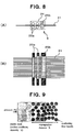
- a plurality of fixed guides 33b each having a semi-circular surface are arranged in the running direction of tape-like reinforcing fiber bundles 31 so that the semi-circular surfaces face alternately toward opposite directions, the molten resin 23 is impregnated in order into the respective tape-like reinforcing fiber bundles 31, and the tape-like reinforcing fiber bundles 31 impregnated with the molten resin 23 are laminated in order.
- the fixed guides can be any of those each having a columnar surface shown in Fig. 4 and those each having a semi-circular surface shown in Fig.
- a certain fixed guide 33b operates only for a specified part of tape-like reinforcing fiber bundles 31 and allows the remaining tape-like reinforcing fiber bundles 31 to merely pass.
- a tunnel 35 capable of passing a part of tape-like reinforcing fiber bundles 31 can be provided to fixed guide 33b.
- a columnar fixed guide 33a such as one in the example shown in Fig. 4
- the tunnel 35 can be provided as shown in Fig. 7 .
- a calendering treatment is performed by calender rolls 24 equipped with a plurality of rolls.
- the width of the sheet-shaped prepreg is regulated so as to become a predetermined width in the width direction while narrowing in width the sheet-shaped prepreg, by passing it through a second calender roll 25b (preferably, a roll with a groove having a predetermined width).
- a second calender roll 25b preferably, a roll with a groove having a predetermined width.
- each of a plurality of tape-like reinforcing fiber bundles 10 used for production of the sheet-shaped prepreg 34 as a final product is reduced in thickness by spreading and widening, and the molten resin 23 is impregnated into each tape-like reinforcing fiber bundle 31 reduced in thickness from both surface sides in the die 19. Therefore, even in case where a resin having a relatively high melt viscosity such as a thermoplastic resin is used, the resin is impregnated into each of tape-like reinforcing fiber bundles 31 sufficiently and satisfactorily in a short time.
- the resin impregnation is performed from both surface sides by a distance (by an impregnation distance) in the direction of the small thickness of the reinforcing fiber bundle 31, and therefore, even in case of the molten resin having a high viscosity, uniform impregnation throughout the whole of the thickness direction can be completed easily in a short time.
- the difficulty of such an impregnation of the molten resin having a high viscosity into the reinforcing fiber bundle can be explained, for example, using a simple model due to Darcy's law represented by Fig. 9 and the following equation.
- the time required for resin impregnation is in proportion to melt viscosity ⁇ , the time becomes longer as the melt viscosity ⁇ becomes higher (namely, becomes harder to impregnate), and it is in proportion to square of impregnation distance X. Since this impregnation distance corresponds to a thickness of each tape-like reinforcing fiber bundle 31, it is understood that, in the present invention, how remarkably it can contribute to shortening of the impregnation time to form tape-like reinforcing fiber bundle 10 as tape-like reinforcing fiber bundle 31 reduced in thickness by spreading and widening.
- each tape-like reinforcing fiber bundle 31 can be shortened, and tape-like reinforcing fiber bundles 31 each impregnated with resin can be merely laminated in the same die to obtain a desired sheet-shaped prepreg, the time for production of the sheet-shaped prepreg can be considerably shortened, and the productivity can be remarkably enhanced.
- the process and apparatus for producing a sheet-shaped prepreg according to the present invention can be applied to production of any sheet-shaped prepreg using continuous reinforcing fibers and a thermoplastic resin.
- a sheet-shaped prepreg obtained from such process and apparatus can be suitably used for transportation equipment such as automobiles, airplanes or ships, etc., and structural components and sub-structural components for leisure and sport parts, pressure vessels, structural oil field excavation or civil engineering and architecture, etc.
Landscapes
- Chemical & Material Sciences (AREA)
- Engineering & Computer Science (AREA)
- Mechanical Engineering (AREA)
- Materials Engineering (AREA)
- Composite Materials (AREA)
- Manufacturing & Machinery (AREA)
- Health & Medical Sciences (AREA)
- Chemical Kinetics & Catalysis (AREA)
- Medicinal Chemistry (AREA)
- Polymers & Plastics (AREA)
- Organic Chemistry (AREA)
- Inorganic Chemistry (AREA)
- Reinforced Plastic Materials (AREA)
Claims (15)
- Procédé de production d'un préimprégné en forme de feuille (34) comprenant les étapes suivantes :une étape d'introduction de faisceau de fibres (1) pour agencer des faisceaux de fibres de renforcement de type bande (10), comprenant chacun une pluralité de fibres de renforcement continues, sous une forme multicouche dans une direction d'épaisseur de chaque faisceau de fibres de renforcement de type bande (10), tout en faisant avancer lesdits faisceaux de fibres de renforcement de type bande (10) en continu, et les introduire dans une matrice (19) à laquelle une résine thermoplastique fondue (23) a été fournie ;une étape de réduction d'épaisseur de faisceau de fibres (2) pour élargir chacun desdits faisceaux de fibres de renforcement de type bande (10) agencés sous ladite forme multicouche par un moyen d'étalement pour réduire une épaisseur de chaque faisceau de fibres de renforcement de type bande (10), à un ou deux des stades avant et après ladite introduction dans ladite matrice (19) ;une étape d'imprégnation de résine (4) pour imprégner chacun desdits faisceaux de fibres de renforcement de type bande (10) d'épaisseur réduite et agencés sous la forme multicouche dans la direction d'épaisseur de chaque faisceau de fibres de renforcement de type bande (10), de ladite résine thermoplastique fondue (23), dans ladite matrice (19) ; etune étape de stratification (6) pour stratifier une pluralité de faisceaux de fibres de renforcement de type bande (10), qui sont en train d'être imprégnés de ladite résine thermoplastique fondue (23) et/ou qui ont été imprégnés de ladite résine thermoplastique fondue (23), dans ladite matrice (19), etdans lequel un préimprégné (34) ayant une forme de type feuille comme sa forme entière est produit.
- Procédé de production d'un préimprégné en forme de feuille (34) selon la revendication 1, dans lequel lesdits faisceaux de fibres de renforcement de type bande (10) agencés sous ladite forme multicouche sont disposés au niveau d'une formation d'une pluralité d'étages, où un espace est donné entre des faisceaux de fibres de renforcement de type bande (10) adjacents, dans ladite direction d'épaisseur de chaque faisceau de fibres de renforcement de type bande (10), à un ou deux des stades avant et après ladite introduction dans ladite matrice (19).
- Procédé de production d'un préimprégné en forme de feuille (34) selon la revendication 1 ou 2, dans lequel, dans ladite étape de réduction d'épaisseur de faisceau de fibres (2), des positions pour l'élargissement de faisceaux de fibres de renforcement de type bande (10) adjacents les uns aux autres parmi lesdits faisceaux de fibres de renforcement de type bande (10) agencés sous ladite forme multicouche par un moyen d'étalement sont décalées les unes par rapport aux autres dans une direction d'avancement desdits faisceaux de fibres de renforcement de type bande (10).
- Procédé de production d'un préimprégné en forme de feuille (34) selon l'une des revendications 1 à 3, dans lequel dans ladite matrice (19), des faisceaux de fibres de renforcement de type bande (10) respectifs sont étalés dans l'ordre et/ou des faisceaux de fibres de renforcement de type bande (10) respectifs ayant été imprégnés de ladite résine thermoplastique fondue (23) sont stratifiés dans l'ordre, en utilisant une pluralité de guides fixes (33a, 33b) agencés dans une direction d'avancement desdits faisceaux de fibres de renforcement de type bande (10), et un tunnel (35) pour faisceaux de fibres de renforcement de type bande (10) est prévu sur chacun d'au moins une partie de ladite pluralité de guides fixes (33a, 33b) utilisés pour ledit étalement et/ou ladite stratification et au moins une partie de faisceaux de fibres de renforcement de type bande (10) avancent à travers ledit tunnel (35).
- Procédé de production d'un préimprégné en forme de feuille (34) selon l'une des revendications 1 à 4, dans lequel, dans ladite étape d'imprégnation de résine (4) ou ladite étape de stratification (6), du gaz et/ou de la résine (23) dans ladite matrice (19) est évacué(e) à partir d'un évent de dégazage (21) et/ou d'un évent de purge de résine (27) prévu sur ladite matrice (19).
- Procédé de production d'un préimprégné en forme de feuille (34) selon l'une des revendications 1 à 5, dans lequel une étape de post-imprégnation (5) est prévue, dans laquelle, après que ledit préimprégné (34) stratifié dans ladite matrice (19) et formé sous la forme d'une feuille comme sa forme entière est tiré de ladite matrice (19), il est en outre passé à travers des rouleaux de calandre (24).
- Procédé de production d'un préimprégné en forme de feuille (34) selon la revendication 6, dans lequel lesdits rouleaux de calandre (24) comprennent au moins un premier rouleau de calandre (25a) et un deuxième rouleau de calandre (25b), au moins ledit deuxième rouleau de calandre (25b) est un rouleau avec une rainure, et après que ledit préimprégné (34) formé sous la forme d'une feuille est élargi en le faisant passer à travers ledit premier rouleau de calandre (25a), une largeur dudit préimprégné en forme de feuille (34) est régulée de manière à devenir une largeur prédéterminée dans une direction de largeur tout en rétrécissant en largeur ledit préimprégné en forme de feuille élargi, en le faisant passer à travers ledit deuxième rouleau de calandre (25b).
- Procédé de production d'un préimprégné en forme de feuille (34) selon l'une des revendications 1 à 7, dans lequel lesdites fibres de renforcement continues comprennent des fibres de carbone.
- Appareil de production d'un préimprégné en forme de feuille (100) dans lequel un préimprégné (34) ayant une forme de type feuille comme sa forme entière est produit, et ledit appareil (100) comprend :une matrice (19) alimentée en résine thermoplastique fondue (23) ;un moyen d'introduction de faisceau de fibres (1) pour agencer des faisceaux de fibres de renforcement de type bande (10), comprenant chacun une pluralité de fibres de renforcement continues, sous une forme multicouche dans une direction d'épaisseur de chaque faisceau de fibres de renforcement de type bande (10), tout en faisant avancer lesdits faisceaux de fibres de renforcement de type bande (10) en continu, et les introduire dans ladite matrice (19) ;un moyen de réduction d'épaisseur de faisceau de fibres (2) pour élargir chacun desdits faisceaux de fibres de renforcement de type bande (10) agencés sous ladite forme multicouche par un moyen d'étalement (12, 13) pour réduire une épaisseur de chaque faisceau de fibres de renforcement de type bande (10), avant ladite introduction dans ladite matrice (19) ;un moyen d'imprégnation de résine (4) pour imprégner chacun desdits faisceaux de fibres de renforcement de type bande (10) d'épaisseur réduite et agencés sous la forme multicouche dans la direction d'épaisseur de chaque faisceau de fibres de renforcement de type bande (10), de ladite résine thermoplastique fondue (23), dans ladite matrice (19) ; etun moyen de stratification (6) pour stratifier une pluralité de faisceaux de fibres de renforcement de type bande (10) qui sont en train d'être imprégnés de ladite résine thermoplastique fondue (23) et/ou qui ont été imprégnés de ladite résine thermoplastique fondue (23), dans ladite matrice (19).
- Appareil (100) pour produire un préimprégné en forme de feuille (34) selon la revendication 9, dans lequel on prévoit un moyen pour disposer lesdits faisceaux de fibres de renforcement de type bande (10) agencés sous ladite forme multicouche au niveau d'une formation d'une pluralité d'étages, où un espace est donné entre des faisceaux de fibres de renforcement de type bande (10) adjacents, dans ladite direction d'épaisseur de chaque faisceau de fibres de renforcement de type bande (10) au niveau d'un ou des deux étage(s) avant et après ladite introduction dans ladite matrice (19).
- Appareil (100) pour produire un préimprégné en forme de feuille (34) selon la revendication 9 ou 10, dans lequel, dans ledit moyen de réduction d'épaisseur de faisceau de fibres (2), des positions pour l'élargissement de faisceaux de fibres de renforcement de type bande (10) adjacents les uns aux autres parmi lesdits faisceaux de fibres de renforcement de type bande (10) agencés sous ladite forme multicouche par un moyen d'étalement sont décalées les unes par rapport aux autres dans une direction d'avancement desdits faisceaux de fibres de renforcement de type bande (10).
- Appareil (100) pour produire un préimprégné en forme de feuille (34) selon l'une des revendications 9 à 11, dans lequel une pluralité de guides fixes (33a, 33b) sont agencés dans ladite matrice (19) dans une direction d'avancement desdits faisceaux de fibres de renforcement de type bande (10), lesdits guides fixes (33a, 33b) étant utilisés pour étaler des faisceaux de fibres de renforcement de type bande (10) respectifs dans l'ordre et/ou stratifier des faisceaux de fibres de renforcement de type bande (10) respectifs ayant été imprégnés de ladite résine thermoplastique fondue (23) dans l'ordre, et un tunnel (35) pour faisceaux de fibres de renforcement de type bande (10) capable de faire avancer au moins une partie de faisceaux de fibres de renforcement de type bande (10) à travers ledit tunnel (35) est prévu sur chacun d'au moins une partie de ladite pluralité de guides fixes (33a, 33b).
- Appareil (100) pour produire un préimprégné en forme de feuille (34) selon l'une des revendications 9 à 12, dans lequel un évent de dégazage (21) et/ou un évent de purge de résine (27) est monté sur ladite matrice (19).
- Appareil (100) pour produire un préimprégné en forme de feuille (34) selon l'une des revendications 9 à 13, dans lequel un moyen de post-imprégnation (5) est prévu qui est disposé à une position en aval par rapport à ladite matrice (19) et qui a des rouleaux de calandre (24) réalisant un traitement de calandrage pour ledit préimprégné (34) stratifié dans ladite matrice (19), formé sous la forme d'une feuille comme sa forme entière et tiré de ladite matrice (19).
- Appareil (100) pour produire un préimprégné en forme de feuille (34) selon la revendication 14, dans lequel lesdits rouleaux de calandre (24) comprennent, au moins, un premier rouleau de calandre (25a) pour élargir ledit préimprégné (34) formé sous la forme d'une feuille de manière à avoir une largeur prédéterminée dans une direction de largeur et un deuxième rouleau de calandre (25b) ayant une rainure disposée à une position en aval par rapport audit premier rouleau de calandre (25a) pour réguler ledit préimprégné en forme de feuille élargi (34) de manière à avoir une largeur prédéterminée dans une direction de largeur tout en rétrécissant en largeur ledit préimprégné en forme de feuille élargi (34).
Applications Claiming Priority (2)
| Application Number | Priority Date | Filing Date | Title |
|---|---|---|---|
| JP2010149295 | 2010-06-30 | ||
| PCT/JP2011/064884 WO2012002417A1 (fr) | 2010-06-30 | 2011-06-29 | Procédé et appareil pour la production d'un préimprégné en forme de feuille |
Publications (3)
| Publication Number | Publication Date |
|---|---|
| EP2589475A1 EP2589475A1 (fr) | 2013-05-08 |
| EP2589475A4 EP2589475A4 (fr) | 2017-11-01 |
| EP2589475B1 true EP2589475B1 (fr) | 2020-06-17 |
Family
ID=45402122
Family Applications (1)
| Application Number | Title | Priority Date | Filing Date |
|---|---|---|---|
| EP11800879.6A Active EP2589475B1 (fr) | 2010-06-30 | 2011-06-29 | Procédé et appareil pour la production d'un préimprégné en forme de feuille |
Country Status (6)
| Country | Link |
|---|---|
| US (1) | US9238336B2 (fr) |
| EP (1) | EP2589475B1 (fr) |
| JP (1) | JP5626660B2 (fr) |
| KR (1) | KR101787143B1 (fr) |
| CN (1) | CN102958657B (fr) |
| WO (1) | WO2012002417A1 (fr) |
Families Citing this family (48)
| Publication number | Priority date | Publication date | Assignee | Title |
|---|---|---|---|---|
| JPWO2014171481A1 (ja) * | 2013-04-19 | 2017-02-23 | 東レ株式会社 | 強化繊維シートの製造方法 |
| CN103496608B (zh) * | 2013-09-29 | 2016-01-13 | 大连橡胶塑料机械股份有限公司 | 胶片连续层合装置 |
| FR3017329B1 (fr) | 2014-02-13 | 2016-07-29 | Arkema France | Procede de fabrication d'un materiau fibreux pre-impregne de polymere thermoplastique en lit fluidise |
| FR3017330B1 (fr) * | 2014-02-13 | 2016-07-22 | Arkema France | Procede de fabrication d'un materiau fibreux pre-impregne de polymere thermoplastique en utilisant une dispersion aqueuse de polymere |
| JP6496833B2 (ja) * | 2015-03-10 | 2019-04-10 | ファイバ リーインフォースト サーモプラスティックス ベー.フェー. | 一方向繊維強化テープを作製するための方法 |
| BR112017021124B1 (pt) * | 2015-04-02 | 2022-03-15 | Evonik Operations Gmbh | Processo para a produção de um material compósito de fibra |
| ES2887827T3 (es) * | 2015-07-07 | 2021-12-28 | Mitsubishi Chem Corp | Usos de un haz de fibras continuas en métodos para la producción de material de moldeo de resina reforzado con fibra |
| JP6625838B2 (ja) * | 2015-07-08 | 2019-12-25 | Towa株式会社 | 加圧装置およびそれを備えた個片化装置、樹脂成形装置、デバイス製造装置、ならびに加圧方法およびそれを含む樹脂成形方法、デバイス製造方法 |
| DE102015220186A1 (de) * | 2015-10-16 | 2017-04-20 | Bayerische Motoren Werke Aktiengesellschaft | Vorrichtung zum Infiltrieren und Spreizen von Faserrovings |
| KR101671916B1 (ko) * | 2015-12-10 | 2016-11-02 | 한국이엠 주식회사 | 섬유강화 플라스틱 제조기의 섬유공급장치 |
| CN111674060A (zh) | 2015-12-25 | 2020-09-18 | 三菱化学株式会社 | 碳纤维束的分纤方法 |
| KR101926462B1 (ko) * | 2016-02-03 | 2018-12-07 | (주)엘지하우시스 | 프리프레그 제조 장치 및 이를 이용한 프리프레그 제조 방법 |
| CN107214877A (zh) * | 2016-03-22 | 2017-09-29 | 翁庆隆 | 纤维束成型半熟化含浸纤维束的装置及制造方法 |
| CN105624874B (zh) * | 2016-03-23 | 2018-05-01 | 江苏澳盛复合材料科技有限公司 | 一种碳纤维展宽设备和工艺 |
| EP3275921A1 (fr) * | 2016-07-27 | 2018-01-31 | Toray Carbon Fibers Europe | Préimprégné comprenant des fibres de renforcement |
| US10543640B2 (en) | 2016-09-06 | 2020-01-28 | Continuous Composites Inc. | Additive manufacturing system having in-head fiber teasing |
| DE102016219553B4 (de) * | 2016-10-07 | 2023-02-16 | ThyssenKrupp Carbon Components GmbH | Pultrusionsverfahren, Verwendung eines Pultrusionsverfahren und Anordnung zur kontinuierlichen Herstellung von Rohlingen aus einem Faser-Kunststoff-Verbundwerkstoff |
| JP6711411B2 (ja) * | 2016-11-11 | 2020-06-17 | 株式会社Ihi | プリプレグシート製造装置 |
| CN106738447B (zh) * | 2016-12-14 | 2018-10-09 | 江苏大学 | 一种连续碳纤维增强热塑性树脂基预浸料制备装置及方法 |
| EP3354433A1 (fr) * | 2017-01-31 | 2018-08-01 | Covestro Deutschland AG | Dispositif de rouleaux de refroidissement libres destiné à fabriquer une matière composite en fibres sous la forme d'un ruban imprégné en polymère, procédé de fabrication dudit ruban, ruban imprégné et composite stratifié fabriqué à partir dudit ruban imprégné |
| ES2909740T3 (es) | 2017-03-23 | 2022-05-10 | Toray Industries | Procedimiento de producción y dispositivo de recubrimiento para el haz de fibras de refuerzo similar a una lámina impregnado con líquido de recubrimiento y un objeto integrado similares a una lámina |
| CN109267182B (zh) * | 2017-07-18 | 2020-12-11 | 翁庆隆 | 碳纤维丝束成形装置及碳纤维丝束成形方法 |
| EP3656807A4 (fr) | 2017-07-18 | 2021-04-07 | Toray Industries, Inc. | Préimprégné sous forme de bande à orientation unidirectionnelle, et article moulé à partir de celui-ci |
| FR3072899A1 (fr) * | 2017-10-31 | 2019-05-03 | Max Sardou | Ruban preimpregne thermodurcissable anti fissuration |
| WO2019111036A1 (fr) * | 2017-12-04 | 2019-06-13 | Annexair Inc. | Panneau composite, matériau composite, imprégneuse et procédé de fabrication d'un panneau composite |
| WO2019111037A1 (fr) | 2017-12-04 | 2019-06-13 | Annexair Inc. | Panneau composite, matériau composite, imprégneuse et procédé de fabrication d'un panneau composite |
| CA3084576A1 (fr) | 2017-12-04 | 2019-06-13 | Annexair Inc. | Panneau composite, materiau composite, impregneuse et procede de fabrication d'un panneau composite |
| CN108099051B (zh) * | 2017-12-18 | 2023-07-07 | 金发科技股份有限公司 | 一种熔融浸渍设备及熔融浸渍方法 |
| CN108099225B (zh) * | 2017-12-18 | 2023-10-31 | 金发科技股份有限公司 | 一种交变压力熔融浸渍设备及熔融浸渍方法 |
| WO2019124203A1 (fr) | 2017-12-22 | 2019-06-27 | 東レ株式会社 | Préimprégné en forme de bande et son procédé de production |
| EP3763773A4 (fr) * | 2018-03-06 | 2021-11-17 | Toray Industries, Inc. | Matériau bande sec destiné à être utilisé pour la mise en place de fibres, procédé de production de celui-ci, et stratifié de fibres de renforcement et article moulé en résine renforcée par des fibres produits chacun à l'aide de ce matériau |
| FR3079163B1 (fr) * | 2018-03-23 | 2021-10-15 | Arkema France | Nappe de materiau fibreux impregne, son procede de fabrication et son utilisation pour la fabrication de pieces composites en trois dimensions |
| DE102018208009A1 (de) | 2018-05-22 | 2019-11-28 | Ubc Composites Gmbh | Verfahren zur Herstellung eines faserverstärkten Bauteils sowie Vorrichtung zur Durchführung des Verfahrens |
| EP3835342A4 (fr) | 2018-08-09 | 2022-05-25 | Toray Industries, Inc. | Procédé de fabrication d'un préimprégné, dispositif de revêtement, et appareil de fabrication d'un préimprégné |
| ES2958957T3 (es) | 2018-08-22 | 2024-02-16 | Toray Industries | Método de producción para material preimpregnado, cinta de material preimpregnado y material compuesto reforzado con fibra, y dispositivo de producción de material preimpregnado |
| WO2020040150A1 (fr) | 2018-08-22 | 2020-02-27 | 東レ株式会社 | Procédé de production d'un préimprégné, ruban préimprégné, et matériau composite renforcé par des fibres, et dispositif de revêtement |
| CN112566766B (zh) * | 2018-08-22 | 2022-12-23 | 东丽株式会社 | 含浸有热塑性树脂的片状增强纤维束的制造方法 |
| JP7243629B2 (ja) | 2018-08-22 | 2023-03-22 | 東レ株式会社 | プリプレグの製造方法および製造装置 |
| WO2020074789A1 (fr) | 2018-10-09 | 2020-04-16 | Max Sardou | Ruban preimpregne thermodurcissable anti fissuration |
| WO2020197707A1 (fr) * | 2019-03-01 | 2020-10-01 | Rensselaer Polytechnic Institute | Système et procédé d'imprégnation in situ de câbles de filaments de fibres continus avec de la résine thermoplastique |
| KR102177348B1 (ko) * | 2019-07-18 | 2020-11-11 | 순천향대학교 산학협력단 | 장섬유 복합재의 제조방법 |
| JP7172947B2 (ja) * | 2019-10-29 | 2022-11-16 | トヨタ自動車株式会社 | 電池パックの製造方法 |
| CN110802852B (zh) * | 2019-11-15 | 2021-03-19 | 南京荣仕景复合材料有限公司 | 连续玻纤增强聚氨酯微孔发泡型材拉挤成型工艺和产品及其拉挤成型系统 |
| DE112020006109T5 (de) * | 2020-03-19 | 2022-11-03 | Hitachi Astemo, Ltd. | Rohrkörper-zwischenstück und verfahren zur herstellung eines rohrkörpers |
| CN111469243B (zh) * | 2020-03-23 | 2022-03-15 | 上海工程技术大学 | 植物纤维增强复合材料层合板的快速制备装置 |
| CN115698146B (zh) * | 2020-07-27 | 2024-03-08 | 东丽株式会社 | 纤维增强成型品的制造方法 |
| CN112847924B (zh) * | 2021-01-07 | 2022-06-10 | 中广核俊尔(浙江)新材料有限公司 | 低散发、低浮纤、低翘曲、超分散长玻纤聚酰胺复合材料及其制备方法 |
| CN116100702A (zh) * | 2023-03-09 | 2023-05-12 | 哈尔滨工业大学 | 一种热塑性树脂基预浸料(带)的熔融浸渍模具及方法 |
Family Cites Families (34)
| Publication number | Priority date | Publication date | Assignee | Title |
|---|---|---|---|---|
| GB1357527A (en) * | 1970-06-25 | 1974-06-26 | Dunlop Holdings Ltd | Manufacture of sheet material |
| US3992240A (en) * | 1975-05-19 | 1976-11-16 | The Boeing Company | Method and apparatus for fabricating elongate laminated structures |
| JPS58205755A (ja) * | 1982-05-27 | 1983-11-30 | 三菱レイヨン株式会社 | ハイブリツド一方向プリプレグ及びその製造法 |
| JPS6036136A (ja) | 1983-08-10 | 1985-02-25 | Toray Ind Inc | 繊維補強熱可塑性樹脂の製造方法 |
| US5277566A (en) * | 1988-10-19 | 1994-01-11 | Hoechst Aktiengesellschaft | Extrusion impregnating device |
| DE4113002A1 (de) * | 1991-04-20 | 1992-10-22 | Teerbau Gmbh Strassenbau | Verfahren zur herstellung eines armierten, haertbaren kunststoffschlauches und vorrichtung dazu |
| JPH05116142A (ja) | 1991-10-29 | 1993-05-14 | Aisin Chem Co Ltd | 長繊維強化複合材の製造装置 |
| JPH0740341A (ja) | 1993-06-29 | 1995-02-10 | Sekisui Chem Co Ltd | 繊維複合シートの製造方法 |
| JPH07251437A (ja) * | 1994-03-15 | 1995-10-03 | Ube Ind Ltd | 長繊維強化熱可塑性複合材料の製造方法およびその製造装置 |
| JP3480990B2 (ja) * | 1994-07-29 | 2003-12-22 | 積水化学工業株式会社 | 繊維複合シートの製造方法 |
| JP3008814B2 (ja) | 1995-04-14 | 2000-02-14 | 松下電工株式会社 | プリプレグの製造方法及びその装置 |
| JPH09111644A (ja) | 1995-10-20 | 1997-04-28 | Toray Ind Inc | 繊維シートの製造方法および装置 |
| US5895622A (en) | 1997-04-07 | 1999-04-20 | Purdue Research Foundation | Method and apparatus for composite manufacture |
| US20010001408A1 (en) * | 1997-11-03 | 2001-05-24 | Harry L. Belvin | Method and apparatus to febricate a fuly-consolidated fiber- reinforced tape from polymer powder preimpregnated fiber tow bundles for automated tow placement |
| JP3830307B2 (ja) | 1999-06-14 | 2006-10-04 | 東邦テナックス株式会社 | 熱可塑性樹脂を含浸した成形材料の製造方法 |
| JP2001162689A (ja) * | 1999-12-08 | 2001-06-19 | Toray Ind Inc | 繊維束搬送方法および搬送装置ならびにプリプレグの製造方法 |
| JP2001262443A (ja) | 2000-01-12 | 2001-09-26 | Toray Ind Inc | 繊維束の開繊装置及び開繊方法並びにプリプレグの製造方法 |
| JP2002363855A (ja) * | 2001-06-07 | 2002-12-18 | Toray Ind Inc | 繊維束の開繊装置および開繊方法ならびにプリプレグの製造方法 |
| US9093191B2 (en) * | 2002-04-23 | 2015-07-28 | CTC Global Corp. | Fiber reinforced composite core for an aluminum conductor cable |
| KR100971686B1 (ko) * | 2002-04-23 | 2010-07-22 | 도레이 카부시키가이샤 | 프리프레그, 그 제조방법 및 성형품 |
| US7571524B2 (en) * | 2003-07-08 | 2009-08-11 | Fukui Prefectural Governmant | Method of producing a spread multi-filament bundle and an apparatus used in the same |
| JP4025820B2 (ja) | 2003-07-08 | 2007-12-26 | 福井県 | 開繊繊維シートの製造方法、および開繊繊維シートの製造装置 |
| JP2005325191A (ja) * | 2004-05-13 | 2005-11-24 | Toray Ind Inc | 一方向性プリプレグの製造方法および製造装置 |
| WO2007013204A1 (fr) * | 2005-07-29 | 2007-02-01 | Toray Industries, Inc. | Tissu renforcé et son procédé de production |
| US8852475B2 (en) * | 2005-12-01 | 2014-10-07 | Saint-Gobain Performance Plastics Corporation | Method of making continuous filament reinforced structural plastic profiles using pultrusion/coextrusion |
| CA2656541A1 (fr) * | 2006-08-18 | 2008-02-21 | Fukui Prefectural Government | Stratifies moules a renfort multiaxial et leur procede de production |
| US20100215887A1 (en) * | 2006-11-22 | 2010-08-26 | Fukui Prefectural Government | Reinforced thermoplastic-resin multilayer sheet material, process for producing the same, and method of forming molded thermoplastic-resin composite material |
| JP5332225B2 (ja) | 2007-02-22 | 2013-11-06 | 東レ株式会社 | 繊維強化複合材料の製造方法 |
| EP3156439B1 (fr) * | 2007-03-20 | 2019-08-21 | Toray Industries, Inc. | Matériau de moulage, préimprégné, matériau composite renforcé par des fibres et procédé de production de matériau de base de moulage renforcé par des fibres |
| JP2008246782A (ja) * | 2007-03-29 | 2008-10-16 | Teijin Techno Products Ltd | 繊維強化熱可塑性樹脂テープ製造装置及び繊維強化熱可塑性樹脂テープの製造方法 |
| JP5326170B2 (ja) * | 2009-05-25 | 2013-10-30 | 福井県 | 繊維束の開繊方法及び開繊糸シート並びに繊維補強シートの製造方法 |
| WO2012096273A1 (fr) * | 2011-01-14 | 2012-07-19 | 東レ株式会社 | Matière de moulage, préimprégné, matière composite renforcée par des fibres, stratifié de matière composite renforcée par des fibres et procédé de fabrication d'une matière de base de moulage renforcée par des fibres |
| KR101775756B1 (ko) * | 2011-03-03 | 2017-09-06 | 미쯔비시 케미컬 주식회사 | 매트릭스 수지 조성물, 프리프레그와 그의 제조 방법, 및 섬유 강화 복합 재료 |
| CA2831358C (fr) * | 2011-04-12 | 2019-04-02 | Ticona Llc | Tiges thermoplastiques renforcees de fibres continues et methode d'extrusion par etirage pour sa fabrication |
-
2011
- 2011-06-29 US US13/806,356 patent/US9238336B2/en not_active Expired - Fee Related
- 2011-06-29 CN CN201180029051.1A patent/CN102958657B/zh active Active
- 2011-06-29 EP EP11800879.6A patent/EP2589475B1/fr active Active
- 2011-06-29 JP JP2011529388A patent/JP5626660B2/ja active Active
- 2011-06-29 WO PCT/JP2011/064884 patent/WO2012002417A1/fr active Application Filing
- 2011-06-29 KR KR1020127033832A patent/KR101787143B1/ko active IP Right Grant
Non-Patent Citations (1)
| Title |
|---|
| None * |
Also Published As
| Publication number | Publication date |
|---|---|
| US9238336B2 (en) | 2016-01-19 |
| CN102958657A (zh) | 2013-03-06 |
| JPWO2012002417A1 (ja) | 2013-08-29 |
| US20130106014A1 (en) | 2013-05-02 |
| KR101787143B1 (ko) | 2017-10-18 |
| EP2589475A4 (fr) | 2017-11-01 |
| JP5626660B2 (ja) | 2014-11-19 |
| EP2589475A1 (fr) | 2013-05-08 |
| KR20130091255A (ko) | 2013-08-16 |
| CN102958657B (zh) | 2015-08-12 |
| WO2012002417A1 (fr) | 2012-01-05 |
Similar Documents
| Publication | Publication Date | Title |
|---|---|---|
| EP2589475B1 (fr) | Procédé et appareil pour la production d'un préimprégné en forme de feuille | |
| JP6496833B2 (ja) | 一方向繊維強化テープを作製するための方法 | |
| KR101321651B1 (ko) | 열가소성 수지 복합 재료 성형품의 성형 방법 | |
| EP2875937B1 (fr) | Renforcement unidirectionnel, son procédé de fabrication et son utilisation | |
| EP3028852B1 (fr) | Matériau composite en résine renforcée par des fibres continues et article moulé associé | |
| WO2008149615A9 (fr) | Faisceau de fibres coupées, matériau de moulage, et plastique renforcé par des fibres, et leur procédé de production | |
| KR20180033170A (ko) | 섬유 강화 수지 시트재의 제조 방법 | |
| US20030157309A1 (en) | Moulding materials | |
| JP5663984B2 (ja) | シート状プリプレグの製造方法および装置 | |
| EP3351362B1 (fr) | Appareil de pultrusion | |
| KR20140085713A (ko) | 연속 탄소섬유 강화 열가소성 프리프레그의 제조 방법 | |
| EP3275921A1 (fr) | Préimprégné comprenant des fibres de renforcement | |
| KR20140005409A (ko) | 열가소성 프리프레그 및 그 제조방법 | |
| KR20190131483A (ko) | 도포액 함침 시트형 강화 섬유 다발 및 시트형 일체물의 제조 방법, 도포 장치 | |
| KR20170100016A (ko) | 섬유 복합 재료를 제조하기 위한 방법 및 장치 | |
| EP3396035B1 (fr) | Matériau composite renforcé par des fibres | |
| KR20180029350A (ko) | 연속 탄소섬유 강화 복합재료의 제조방법과 복합성형체의 제조방법 | |
| US20150101756A1 (en) | Process | |
| EP3835037A1 (fr) | Matériau de ruban de fibres renforcées et son procédé de production, corps moulé de résine renforcée de fibres et corps stratifié de fibres renforcées utilisant un matériau de ruban de fibres renforcées | |
| KR20200141725A (ko) | 섬유강화 복합재료 제조용 복합섬유 원단 및 이를 이용한 섬유강화 복합재료의 성형방법 | |
| KR20190075568A (ko) | 섬유-열가소성 수지 복합재의 제조 방법 | |
| US11465372B2 (en) | Dry tape material for fiber placement, method of manufacturing the same, and reinforcing fiber laminate and fiber-reinforced plastic molded body produced with the same | |
| WO2018083735A1 (fr) | Substrat de renfort de matériau composite, matériau composite, et procédé de production d'un substrat de renfort de matériau composite |
Legal Events
| Date | Code | Title | Description |
|---|---|---|---|
| PUAI | Public reference made under article 153(3) epc to a published international application that has entered the european phase |
Free format text: ORIGINAL CODE: 0009012 |
|
| 17P | Request for examination filed |
Effective date: 20121218 |
|
| AK | Designated contracting states |
Kind code of ref document: A1 Designated state(s): AL AT BE BG CH CY CZ DE DK EE ES FI FR GB GR HR HU IE IS IT LI LT LU LV MC MK MT NL NO PL PT RO RS SE SI SK SM TR |
|
| DAX | Request for extension of the european patent (deleted) | ||
| RA4 | Supplementary search report drawn up and despatched (corrected) |
Effective date: 20171002 |
|
| RIC1 | Information provided on ipc code assigned before grant |
Ipc: B29B 11/16 20060101AFI20170925BHEP Ipc: B29B 15/12 20060101ALI20170925BHEP Ipc: C08J 5/24 20060101ALI20170925BHEP Ipc: B29C 70/50 20060101ALI20170925BHEP |
|
| STAA | Information on the status of an ep patent application or granted ep patent |
Free format text: STATUS: EXAMINATION IS IN PROGRESS |
|
| 17Q | First examination report despatched |
Effective date: 20190218 |
|
| GRAP | Despatch of communication of intention to grant a patent |
Free format text: ORIGINAL CODE: EPIDOSNIGR1 |
|
| STAA | Information on the status of an ep patent application or granted ep patent |
Free format text: STATUS: GRANT OF PATENT IS INTENDED |
|
| INTG | Intention to grant announced |
Effective date: 20200218 |
|
| GRAS | Grant fee paid |
Free format text: ORIGINAL CODE: EPIDOSNIGR3 |
|
| GRAA | (expected) grant |
Free format text: ORIGINAL CODE: 0009210 |
|
| STAA | Information on the status of an ep patent application or granted ep patent |
Free format text: STATUS: THE PATENT HAS BEEN GRANTED |
|
| AK | Designated contracting states |
Kind code of ref document: B1 Designated state(s): AL AT BE BG CH CY CZ DE DK EE ES FI FR GB GR HR HU IE IS IT LI LT LU LV MC MK MT NL NO PL PT RO RS SE SI SK SM TR |
|
| REG | Reference to a national code |
Ref country code: GB Ref legal event code: FG4D |
|
| REG | Reference to a national code |
Ref country code: CH Ref legal event code: EP |
|
| REG | Reference to a national code |
Ref country code: IE Ref legal event code: FG4D |
|
| REG | Reference to a national code |
Ref country code: DE Ref legal event code: R096 Ref document number: 602011067378 Country of ref document: DE |
|
| REG | Reference to a national code |
Ref country code: AT Ref legal event code: REF Ref document number: 1280765 Country of ref document: AT Kind code of ref document: T Effective date: 20200715 |
|
| REG | Reference to a national code |
Ref country code: NL Ref legal event code: FP |
|
| PG25 | Lapsed in a contracting state [announced via postgrant information from national office to epo] |
Ref country code: GR Free format text: LAPSE BECAUSE OF FAILURE TO SUBMIT A TRANSLATION OF THE DESCRIPTION OR TO PAY THE FEE WITHIN THE PRESCRIBED TIME-LIMIT Effective date: 20200918 Ref country code: LT Free format text: LAPSE BECAUSE OF FAILURE TO SUBMIT A TRANSLATION OF THE DESCRIPTION OR TO PAY THE FEE WITHIN THE PRESCRIBED TIME-LIMIT Effective date: 20200617 Ref country code: SE Free format text: LAPSE BECAUSE OF FAILURE TO SUBMIT A TRANSLATION OF THE DESCRIPTION OR TO PAY THE FEE WITHIN THE PRESCRIBED TIME-LIMIT Effective date: 20200617 Ref country code: NO Free format text: LAPSE BECAUSE OF FAILURE TO SUBMIT A TRANSLATION OF THE DESCRIPTION OR TO PAY THE FEE WITHIN THE PRESCRIBED TIME-LIMIT Effective date: 20200917 Ref country code: FI Free format text: LAPSE BECAUSE OF FAILURE TO SUBMIT A TRANSLATION OF THE DESCRIPTION OR TO PAY THE FEE WITHIN THE PRESCRIBED TIME-LIMIT Effective date: 20200617 |
|
| REG | Reference to a national code |
Ref country code: LT Ref legal event code: MG4D |
|
| PG25 | Lapsed in a contracting state [announced via postgrant information from national office to epo] |
Ref country code: BG Free format text: LAPSE BECAUSE OF FAILURE TO SUBMIT A TRANSLATION OF THE DESCRIPTION OR TO PAY THE FEE WITHIN THE PRESCRIBED TIME-LIMIT Effective date: 20200917 Ref country code: LV Free format text: LAPSE BECAUSE OF FAILURE TO SUBMIT A TRANSLATION OF THE DESCRIPTION OR TO PAY THE FEE WITHIN THE PRESCRIBED TIME-LIMIT Effective date: 20200617 Ref country code: HR Free format text: LAPSE BECAUSE OF FAILURE TO SUBMIT A TRANSLATION OF THE DESCRIPTION OR TO PAY THE FEE WITHIN THE PRESCRIBED TIME-LIMIT Effective date: 20200617 Ref country code: RS Free format text: LAPSE BECAUSE OF FAILURE TO SUBMIT A TRANSLATION OF THE DESCRIPTION OR TO PAY THE FEE WITHIN THE PRESCRIBED TIME-LIMIT Effective date: 20200617 |
|
| PG25 | Lapsed in a contracting state [announced via postgrant information from national office to epo] |
Ref country code: AL Free format text: LAPSE BECAUSE OF FAILURE TO SUBMIT A TRANSLATION OF THE DESCRIPTION OR TO PAY THE FEE WITHIN THE PRESCRIBED TIME-LIMIT Effective date: 20200617 |
|
| PG25 | Lapsed in a contracting state [announced via postgrant information from national office to epo] |
Ref country code: PT Free format text: LAPSE BECAUSE OF FAILURE TO SUBMIT A TRANSLATION OF THE DESCRIPTION OR TO PAY THE FEE WITHIN THE PRESCRIBED TIME-LIMIT Effective date: 20201019 Ref country code: CZ Free format text: LAPSE BECAUSE OF FAILURE TO SUBMIT A TRANSLATION OF THE DESCRIPTION OR TO PAY THE FEE WITHIN THE PRESCRIBED TIME-LIMIT Effective date: 20200617 Ref country code: ES Free format text: LAPSE BECAUSE OF FAILURE TO SUBMIT A TRANSLATION OF THE DESCRIPTION OR TO PAY THE FEE WITHIN THE PRESCRIBED TIME-LIMIT Effective date: 20200617 Ref country code: RO Free format text: LAPSE BECAUSE OF FAILURE TO SUBMIT A TRANSLATION OF THE DESCRIPTION OR TO PAY THE FEE WITHIN THE PRESCRIBED TIME-LIMIT Effective date: 20200617 Ref country code: SM Free format text: LAPSE BECAUSE OF FAILURE TO SUBMIT A TRANSLATION OF THE DESCRIPTION OR TO PAY THE FEE WITHIN THE PRESCRIBED TIME-LIMIT Effective date: 20200617 Ref country code: EE Free format text: LAPSE BECAUSE OF FAILURE TO SUBMIT A TRANSLATION OF THE DESCRIPTION OR TO PAY THE FEE WITHIN THE PRESCRIBED TIME-LIMIT Effective date: 20200617 |
|
| REG | Reference to a national code |
Ref country code: CH Ref legal event code: PL |
|
| PG25 | Lapsed in a contracting state [announced via postgrant information from national office to epo] |
Ref country code: SK Free format text: LAPSE BECAUSE OF FAILURE TO SUBMIT A TRANSLATION OF THE DESCRIPTION OR TO PAY THE FEE WITHIN THE PRESCRIBED TIME-LIMIT Effective date: 20200617 Ref country code: PL Free format text: LAPSE BECAUSE OF FAILURE TO SUBMIT A TRANSLATION OF THE DESCRIPTION OR TO PAY THE FEE WITHIN THE PRESCRIBED TIME-LIMIT Effective date: 20200617 Ref country code: IS Free format text: LAPSE BECAUSE OF FAILURE TO SUBMIT A TRANSLATION OF THE DESCRIPTION OR TO PAY THE FEE WITHIN THE PRESCRIBED TIME-LIMIT Effective date: 20201017 |
|
| REG | Reference to a national code |
Ref country code: DE Ref legal event code: R097 Ref document number: 602011067378 Country of ref document: DE |
|
| PG25 | Lapsed in a contracting state [announced via postgrant information from national office to epo] |
Ref country code: LU Free format text: LAPSE BECAUSE OF NON-PAYMENT OF DUE FEES Effective date: 20200629 Ref country code: MC Free format text: LAPSE BECAUSE OF FAILURE TO SUBMIT A TRANSLATION OF THE DESCRIPTION OR TO PAY THE FEE WITHIN THE PRESCRIBED TIME-LIMIT Effective date: 20200617 |
|
| REG | Reference to a national code |
Ref country code: BE Ref legal event code: MM Effective date: 20200630 |
|
| PLBE | No opposition filed within time limit |
Free format text: ORIGINAL CODE: 0009261 |
|
| STAA | Information on the status of an ep patent application or granted ep patent |
Free format text: STATUS: NO OPPOSITION FILED WITHIN TIME LIMIT |
|
| PG25 | Lapsed in a contracting state [announced via postgrant information from national office to epo] |
Ref country code: DK Free format text: LAPSE BECAUSE OF FAILURE TO SUBMIT A TRANSLATION OF THE DESCRIPTION OR TO PAY THE FEE WITHIN THE PRESCRIBED TIME-LIMIT Effective date: 20200617 Ref country code: CH Free format text: LAPSE BECAUSE OF NON-PAYMENT OF DUE FEES Effective date: 20200630 Ref country code: LI Free format text: LAPSE BECAUSE OF NON-PAYMENT OF DUE FEES Effective date: 20200630 Ref country code: IE Free format text: LAPSE BECAUSE OF NON-PAYMENT OF DUE FEES Effective date: 20200629 |
|
| REG | Reference to a national code |
Ref country code: AT Ref legal event code: UEP Ref document number: 1280765 Country of ref document: AT Kind code of ref document: T Effective date: 20200617 |
|
| 26N | No opposition filed |
Effective date: 20210318 |
|
| PG25 | Lapsed in a contracting state [announced via postgrant information from national office to epo] |
Ref country code: BE Free format text: LAPSE BECAUSE OF NON-PAYMENT OF DUE FEES Effective date: 20200630 Ref country code: SI Free format text: LAPSE BECAUSE OF FAILURE TO SUBMIT A TRANSLATION OF THE DESCRIPTION OR TO PAY THE FEE WITHIN THE PRESCRIBED TIME-LIMIT Effective date: 20200617 |
|
| PGFP | Annual fee paid to national office [announced via postgrant information from national office to epo] |
Ref country code: IT Payment date: 20210511 Year of fee payment: 11 |
|
| PGFP | Annual fee paid to national office [announced via postgrant information from national office to epo] |
Ref country code: AT Payment date: 20210525 Year of fee payment: 11 |
|
| PG25 | Lapsed in a contracting state [announced via postgrant information from national office to epo] |
Ref country code: TR Free format text: LAPSE BECAUSE OF FAILURE TO SUBMIT A TRANSLATION OF THE DESCRIPTION OR TO PAY THE FEE WITHIN THE PRESCRIBED TIME-LIMIT Effective date: 20200617 Ref country code: MT Free format text: LAPSE BECAUSE OF FAILURE TO SUBMIT A TRANSLATION OF THE DESCRIPTION OR TO PAY THE FEE WITHIN THE PRESCRIBED TIME-LIMIT Effective date: 20200617 Ref country code: CY Free format text: LAPSE BECAUSE OF FAILURE TO SUBMIT A TRANSLATION OF THE DESCRIPTION OR TO PAY THE FEE WITHIN THE PRESCRIBED TIME-LIMIT Effective date: 20200617 |
|
| PG25 | Lapsed in a contracting state [announced via postgrant information from national office to epo] |
Ref country code: MK Free format text: LAPSE BECAUSE OF FAILURE TO SUBMIT A TRANSLATION OF THE DESCRIPTION OR TO PAY THE FEE WITHIN THE PRESCRIBED TIME-LIMIT Effective date: 20200617 |
|
| REG | Reference to a national code |
Ref country code: AT Ref legal event code: MM01 Ref document number: 1280765 Country of ref document: AT Kind code of ref document: T Effective date: 20220629 |
|
| PG25 | Lapsed in a contracting state [announced via postgrant information from national office to epo] |
Ref country code: AT Free format text: LAPSE BECAUSE OF NON-PAYMENT OF DUE FEES Effective date: 20220629 |
|
| P01 | Opt-out of the competence of the unified patent court (upc) registered |
Effective date: 20230515 |
|
| PG25 | Lapsed in a contracting state [announced via postgrant information from national office to epo] |
Ref country code: IT Free format text: LAPSE BECAUSE OF NON-PAYMENT OF DUE FEES Effective date: 20220629 |
|
| PGFP | Annual fee paid to national office [announced via postgrant information from national office to epo] |
Ref country code: NL Payment date: 20230515 Year of fee payment: 13 Ref country code: FR Payment date: 20230510 Year of fee payment: 13 Ref country code: DE Payment date: 20230502 Year of fee payment: 13 |
|
| PGFP | Annual fee paid to national office [announced via postgrant information from national office to epo] |
Ref country code: GB Payment date: 20230511 Year of fee payment: 13 |