EP2586643A1 - Stromversorgungsvorrichtung für ein elektrofahrzeug - Google Patents
Stromversorgungsvorrichtung für ein elektrofahrzeug Download PDFInfo
- Publication number
- EP2586643A1 EP2586643A1 EP11797814.8A EP11797814A EP2586643A1 EP 2586643 A1 EP2586643 A1 EP 2586643A1 EP 11797814 A EP11797814 A EP 11797814A EP 2586643 A1 EP2586643 A1 EP 2586643A1
- Authority
- EP
- European Patent Office
- Prior art keywords
- inverter
- circuit
- electrical circuit
- main
- voltage
- Prior art date
- Legal status (The legal status is an assumption and is not a legal conclusion. Google has not performed a legal analysis and makes no representation as to the accuracy of the status listed.)
- Granted
Links
- 230000001172 regenerating effect Effects 0.000 claims description 14
- 230000007423 decrease Effects 0.000 description 19
- 238000004378 air conditioning Methods 0.000 description 16
- 238000000034 method Methods 0.000 description 11
- 230000001276 controlling effect Effects 0.000 description 8
- 230000001360 synchronised effect Effects 0.000 description 8
- 238000010586 diagram Methods 0.000 description 6
- 230000001133 acceleration Effects 0.000 description 3
- 239000004065 semiconductor Substances 0.000 description 3
- CURLTUGMZLYLDI-UHFFFAOYSA-N Carbon dioxide Chemical compound O=C=O CURLTUGMZLYLDI-UHFFFAOYSA-N 0.000 description 2
- PXHVJJICTQNCMI-UHFFFAOYSA-N Nickel Chemical compound [Ni] PXHVJJICTQNCMI-UHFFFAOYSA-N 0.000 description 2
- 239000003990 capacitor Substances 0.000 description 2
- 238000005516 engineering process Methods 0.000 description 2
- 230000006698 induction Effects 0.000 description 2
- 230000001105 regulatory effect Effects 0.000 description 2
- 238000006467 substitution reaction Methods 0.000 description 2
- UFHFLCQGNIYNRP-UHFFFAOYSA-N Hydrogen Chemical compound [H][H] UFHFLCQGNIYNRP-UHFFFAOYSA-N 0.000 description 1
- HBBGRARXTFLTSG-UHFFFAOYSA-N Lithium ion Chemical compound [Li+] HBBGRARXTFLTSG-UHFFFAOYSA-N 0.000 description 1
- 229910002092 carbon dioxide Inorganic materials 0.000 description 1
- 239000001569 carbon dioxide Substances 0.000 description 1
- 238000006243 chemical reaction Methods 0.000 description 1
- 230000006835 compression Effects 0.000 description 1
- 238000007906 compression Methods 0.000 description 1
- 230000000694 effects Effects 0.000 description 1
- 229910052739 hydrogen Inorganic materials 0.000 description 1
- 239000001257 hydrogen Substances 0.000 description 1
- 229910001416 lithium ion Inorganic materials 0.000 description 1
- 239000000463 material Substances 0.000 description 1
- 229910052759 nickel Inorganic materials 0.000 description 1
- 239000003208 petroleum Substances 0.000 description 1
- 230000001052 transient effect Effects 0.000 description 1
Images


Classifications
-
- H—ELECTRICITY
- H02—GENERATION; CONVERSION OR DISTRIBUTION OF ELECTRIC POWER
- H02J—CIRCUIT ARRANGEMENTS OR SYSTEMS FOR SUPPLYING OR DISTRIBUTING ELECTRIC POWER; SYSTEMS FOR STORING ELECTRIC ENERGY
- H02J1/00—Circuit arrangements for dc mains or dc distribution networks
- H02J1/10—Parallel operation of dc sources
-
- B—PERFORMING OPERATIONS; TRANSPORTING
- B60—VEHICLES IN GENERAL
- B60H—ARRANGEMENTS OF HEATING, COOLING, VENTILATING OR OTHER AIR-TREATING DEVICES SPECIALLY ADAPTED FOR PASSENGER OR GOODS SPACES OF VEHICLES
- B60H1/00—Heating, cooling or ventilating [HVAC] devices
- B60H1/00642—Control systems or circuits; Control members or indication devices for heating, cooling or ventilating devices
- B60H1/00735—Control systems or circuits characterised by their input, i.e. by the detection, measurement or calculation of particular conditions, e.g. signal treatment, dynamic models
- B60H1/00764—Control systems or circuits characterised by their input, i.e. by the detection, measurement or calculation of particular conditions, e.g. signal treatment, dynamic models the input being a vehicle driving condition, e.g. speed
-
- B—PERFORMING OPERATIONS; TRANSPORTING
- B60—VEHICLES IN GENERAL
- B60L—PROPULSION OF ELECTRICALLY-PROPELLED VEHICLES; SUPPLYING ELECTRIC POWER FOR AUXILIARY EQUIPMENT OF ELECTRICALLY-PROPELLED VEHICLES; ELECTRODYNAMIC BRAKE SYSTEMS FOR VEHICLES IN GENERAL; MAGNETIC SUSPENSION OR LEVITATION FOR VEHICLES; MONITORING OPERATING VARIABLES OF ELECTRICALLY-PROPELLED VEHICLES; ELECTRIC SAFETY DEVICES FOR ELECTRICALLY-PROPELLED VEHICLES
- B60L1/00—Supplying electric power to auxiliary equipment of vehicles
- B60L1/003—Supplying electric power to auxiliary equipment of vehicles to auxiliary motors, e.g. for pumps, compressors
-
- B—PERFORMING OPERATIONS; TRANSPORTING
- B60—VEHICLES IN GENERAL
- B60L—PROPULSION OF ELECTRICALLY-PROPELLED VEHICLES; SUPPLYING ELECTRIC POWER FOR AUXILIARY EQUIPMENT OF ELECTRICALLY-PROPELLED VEHICLES; ELECTRODYNAMIC BRAKE SYSTEMS FOR VEHICLES IN GENERAL; MAGNETIC SUSPENSION OR LEVITATION FOR VEHICLES; MONITORING OPERATING VARIABLES OF ELECTRICALLY-PROPELLED VEHICLES; ELECTRIC SAFETY DEVICES FOR ELECTRICALLY-PROPELLED VEHICLES
- B60L1/00—Supplying electric power to auxiliary equipment of vehicles
- B60L1/02—Supplying electric power to auxiliary equipment of vehicles to electric heating circuits
-
- B—PERFORMING OPERATIONS; TRANSPORTING
- B60—VEHICLES IN GENERAL
- B60L—PROPULSION OF ELECTRICALLY-PROPELLED VEHICLES; SUPPLYING ELECTRIC POWER FOR AUXILIARY EQUIPMENT OF ELECTRICALLY-PROPELLED VEHICLES; ELECTRODYNAMIC BRAKE SYSTEMS FOR VEHICLES IN GENERAL; MAGNETIC SUSPENSION OR LEVITATION FOR VEHICLES; MONITORING OPERATING VARIABLES OF ELECTRICALLY-PROPELLED VEHICLES; ELECTRIC SAFETY DEVICES FOR ELECTRICALLY-PROPELLED VEHICLES
- B60L15/00—Methods, circuits, or devices for controlling the traction-motor speed of electrically-propelled vehicles
- B60L15/20—Methods, circuits, or devices for controlling the traction-motor speed of electrically-propelled vehicles for control of the vehicle or its driving motor to achieve a desired performance, e.g. speed, torque, programmed variation of speed
- B60L15/2009—Methods, circuits, or devices for controlling the traction-motor speed of electrically-propelled vehicles for control of the vehicle or its driving motor to achieve a desired performance, e.g. speed, torque, programmed variation of speed for braking
-
- B—PERFORMING OPERATIONS; TRANSPORTING
- B60—VEHICLES IN GENERAL
- B60L—PROPULSION OF ELECTRICALLY-PROPELLED VEHICLES; SUPPLYING ELECTRIC POWER FOR AUXILIARY EQUIPMENT OF ELECTRICALLY-PROPELLED VEHICLES; ELECTRODYNAMIC BRAKE SYSTEMS FOR VEHICLES IN GENERAL; MAGNETIC SUSPENSION OR LEVITATION FOR VEHICLES; MONITORING OPERATING VARIABLES OF ELECTRICALLY-PROPELLED VEHICLES; ELECTRIC SAFETY DEVICES FOR ELECTRICALLY-PROPELLED VEHICLES
- B60L50/00—Electric propulsion with power supplied within the vehicle
- B60L50/50—Electric propulsion with power supplied within the vehicle using propulsion power supplied by batteries or fuel cells
- B60L50/51—Electric propulsion with power supplied within the vehicle using propulsion power supplied by batteries or fuel cells characterised by AC-motors
-
- B—PERFORMING OPERATIONS; TRANSPORTING
- B60—VEHICLES IN GENERAL
- B60L—PROPULSION OF ELECTRICALLY-PROPELLED VEHICLES; SUPPLYING ELECTRIC POWER FOR AUXILIARY EQUIPMENT OF ELECTRICALLY-PROPELLED VEHICLES; ELECTRODYNAMIC BRAKE SYSTEMS FOR VEHICLES IN GENERAL; MAGNETIC SUSPENSION OR LEVITATION FOR VEHICLES; MONITORING OPERATING VARIABLES OF ELECTRICALLY-PROPELLED VEHICLES; ELECTRIC SAFETY DEVICES FOR ELECTRICALLY-PROPELLED VEHICLES
- B60L7/00—Electrodynamic brake systems for vehicles in general
- B60L7/10—Dynamic electric regenerative braking
- B60L7/14—Dynamic electric regenerative braking for vehicles propelled by ac motors
-
- H—ELECTRICITY
- H02—GENERATION; CONVERSION OR DISTRIBUTION OF ELECTRIC POWER
- H02P—CONTROL OR REGULATION OF ELECTRIC MOTORS, ELECTRIC GENERATORS OR DYNAMO-ELECTRIC CONVERTERS; CONTROLLING TRANSFORMERS, REACTORS OR CHOKE COILS
- H02P27/00—Arrangements or methods for the control of AC motors characterised by the kind of supply voltage
- H02P27/04—Arrangements or methods for the control of AC motors characterised by the kind of supply voltage using variable-frequency supply voltage, e.g. inverter or converter supply voltage
- H02P27/06—Arrangements or methods for the control of AC motors characterised by the kind of supply voltage using variable-frequency supply voltage, e.g. inverter or converter supply voltage using dc to ac converters or inverters
- H02P27/08—Arrangements or methods for the control of AC motors characterised by the kind of supply voltage using variable-frequency supply voltage, e.g. inverter or converter supply voltage using dc to ac converters or inverters with pulse width modulation
-
- B—PERFORMING OPERATIONS; TRANSPORTING
- B60—VEHICLES IN GENERAL
- B60L—PROPULSION OF ELECTRICALLY-PROPELLED VEHICLES; SUPPLYING ELECTRIC POWER FOR AUXILIARY EQUIPMENT OF ELECTRICALLY-PROPELLED VEHICLES; ELECTRODYNAMIC BRAKE SYSTEMS FOR VEHICLES IN GENERAL; MAGNETIC SUSPENSION OR LEVITATION FOR VEHICLES; MONITORING OPERATING VARIABLES OF ELECTRICALLY-PROPELLED VEHICLES; ELECTRIC SAFETY DEVICES FOR ELECTRICALLY-PROPELLED VEHICLES
- B60L2210/00—Converter types
- B60L2210/10—DC to DC converters
-
- B—PERFORMING OPERATIONS; TRANSPORTING
- B60—VEHICLES IN GENERAL
- B60L—PROPULSION OF ELECTRICALLY-PROPELLED VEHICLES; SUPPLYING ELECTRIC POWER FOR AUXILIARY EQUIPMENT OF ELECTRICALLY-PROPELLED VEHICLES; ELECTRODYNAMIC BRAKE SYSTEMS FOR VEHICLES IN GENERAL; MAGNETIC SUSPENSION OR LEVITATION FOR VEHICLES; MONITORING OPERATING VARIABLES OF ELECTRICALLY-PROPELLED VEHICLES; ELECTRIC SAFETY DEVICES FOR ELECTRICALLY-PROPELLED VEHICLES
- B60L2210/00—Converter types
- B60L2210/40—DC to AC converters
-
- B—PERFORMING OPERATIONS; TRANSPORTING
- B60—VEHICLES IN GENERAL
- B60L—PROPULSION OF ELECTRICALLY-PROPELLED VEHICLES; SUPPLYING ELECTRIC POWER FOR AUXILIARY EQUIPMENT OF ELECTRICALLY-PROPELLED VEHICLES; ELECTRODYNAMIC BRAKE SYSTEMS FOR VEHICLES IN GENERAL; MAGNETIC SUSPENSION OR LEVITATION FOR VEHICLES; MONITORING OPERATING VARIABLES OF ELECTRICALLY-PROPELLED VEHICLES; ELECTRIC SAFETY DEVICES FOR ELECTRICALLY-PROPELLED VEHICLES
- B60L2240/00—Control parameters of input or output; Target parameters
- B60L2240/10—Vehicle control parameters
- B60L2240/34—Cabin temperature
-
- B—PERFORMING OPERATIONS; TRANSPORTING
- B60—VEHICLES IN GENERAL
- B60L—PROPULSION OF ELECTRICALLY-PROPELLED VEHICLES; SUPPLYING ELECTRIC POWER FOR AUXILIARY EQUIPMENT OF ELECTRICALLY-PROPELLED VEHICLES; ELECTRODYNAMIC BRAKE SYSTEMS FOR VEHICLES IN GENERAL; MAGNETIC SUSPENSION OR LEVITATION FOR VEHICLES; MONITORING OPERATING VARIABLES OF ELECTRICALLY-PROPELLED VEHICLES; ELECTRIC SAFETY DEVICES FOR ELECTRICALLY-PROPELLED VEHICLES
- B60L2240/00—Control parameters of input or output; Target parameters
- B60L2240/40—Drive Train control parameters
- B60L2240/42—Drive Train control parameters related to electric machines
- B60L2240/427—Voltage
-
- B—PERFORMING OPERATIONS; TRANSPORTING
- B60—VEHICLES IN GENERAL
- B60L—PROPULSION OF ELECTRICALLY-PROPELLED VEHICLES; SUPPLYING ELECTRIC POWER FOR AUXILIARY EQUIPMENT OF ELECTRICALLY-PROPELLED VEHICLES; ELECTRODYNAMIC BRAKE SYSTEMS FOR VEHICLES IN GENERAL; MAGNETIC SUSPENSION OR LEVITATION FOR VEHICLES; MONITORING OPERATING VARIABLES OF ELECTRICALLY-PROPELLED VEHICLES; ELECTRIC SAFETY DEVICES FOR ELECTRICALLY-PROPELLED VEHICLES
- B60L2240/00—Control parameters of input or output; Target parameters
- B60L2240/40—Drive Train control parameters
- B60L2240/52—Drive Train control parameters related to converters
- B60L2240/527—Voltage
-
- B—PERFORMING OPERATIONS; TRANSPORTING
- B60—VEHICLES IN GENERAL
- B60L—PROPULSION OF ELECTRICALLY-PROPELLED VEHICLES; SUPPLYING ELECTRIC POWER FOR AUXILIARY EQUIPMENT OF ELECTRICALLY-PROPELLED VEHICLES; ELECTRODYNAMIC BRAKE SYSTEMS FOR VEHICLES IN GENERAL; MAGNETIC SUSPENSION OR LEVITATION FOR VEHICLES; MONITORING OPERATING VARIABLES OF ELECTRICALLY-PROPELLED VEHICLES; ELECTRIC SAFETY DEVICES FOR ELECTRICALLY-PROPELLED VEHICLES
- B60L2240/00—Control parameters of input or output; Target parameters
- B60L2240/40—Drive Train control parameters
- B60L2240/54—Drive Train control parameters related to batteries
- B60L2240/547—Voltage
-
- H—ELECTRICITY
- H02—GENERATION; CONVERSION OR DISTRIBUTION OF ELECTRIC POWER
- H02J—CIRCUIT ARRANGEMENTS OR SYSTEMS FOR SUPPLYING OR DISTRIBUTING ELECTRIC POWER; SYSTEMS FOR STORING ELECTRIC ENERGY
- H02J2310/00—The network for supplying or distributing electric power characterised by its spatial reach or by the load
- H02J2310/40—The network being an on-board power network, i.e. within a vehicle
- H02J2310/48—The network being an on-board power network, i.e. within a vehicle for electric vehicles [EV] or hybrid vehicles [HEV]
-
- H—ELECTRICITY
- H02—GENERATION; CONVERSION OR DISTRIBUTION OF ELECTRIC POWER
- H02P—CONTROL OR REGULATION OF ELECTRIC MOTORS, ELECTRIC GENERATORS OR DYNAMO-ELECTRIC CONVERTERS; CONTROLLING TRANSFORMERS, REACTORS OR CHOKE COILS
- H02P2201/00—Indexing scheme relating to controlling arrangements characterised by the converter used
- H02P2201/07—DC-DC step-up or step-down converter inserted between the power supply and the inverter supplying the motor, e.g. to control voltage source fluctuations, to vary the motor speed
-
- Y—GENERAL TAGGING OF NEW TECHNOLOGICAL DEVELOPMENTS; GENERAL TAGGING OF CROSS-SECTIONAL TECHNOLOGIES SPANNING OVER SEVERAL SECTIONS OF THE IPC; TECHNICAL SUBJECTS COVERED BY FORMER USPC CROSS-REFERENCE ART COLLECTIONS [XRACs] AND DIGESTS
- Y02—TECHNOLOGIES OR APPLICATIONS FOR MITIGATION OR ADAPTATION AGAINST CLIMATE CHANGE
- Y02T—CLIMATE CHANGE MITIGATION TECHNOLOGIES RELATED TO TRANSPORTATION
- Y02T10/00—Road transport of goods or passengers
- Y02T10/60—Other road transportation technologies with climate change mitigation effect
- Y02T10/64—Electric machine technologies in electromobility
-
- Y—GENERAL TAGGING OF NEW TECHNOLOGICAL DEVELOPMENTS; GENERAL TAGGING OF CROSS-SECTIONAL TECHNOLOGIES SPANNING OVER SEVERAL SECTIONS OF THE IPC; TECHNICAL SUBJECTS COVERED BY FORMER USPC CROSS-REFERENCE ART COLLECTIONS [XRACs] AND DIGESTS
- Y02—TECHNOLOGIES OR APPLICATIONS FOR MITIGATION OR ADAPTATION AGAINST CLIMATE CHANGE
- Y02T—CLIMATE CHANGE MITIGATION TECHNOLOGIES RELATED TO TRANSPORTATION
- Y02T10/00—Road transport of goods or passengers
- Y02T10/60—Other road transportation technologies with climate change mitigation effect
- Y02T10/70—Energy storage systems for electromobility, e.g. batteries
-
- Y—GENERAL TAGGING OF NEW TECHNOLOGICAL DEVELOPMENTS; GENERAL TAGGING OF CROSS-SECTIONAL TECHNOLOGIES SPANNING OVER SEVERAL SECTIONS OF THE IPC; TECHNICAL SUBJECTS COVERED BY FORMER USPC CROSS-REFERENCE ART COLLECTIONS [XRACs] AND DIGESTS
- Y02—TECHNOLOGIES OR APPLICATIONS FOR MITIGATION OR ADAPTATION AGAINST CLIMATE CHANGE
- Y02T—CLIMATE CHANGE MITIGATION TECHNOLOGIES RELATED TO TRANSPORTATION
- Y02T10/00—Road transport of goods or passengers
- Y02T10/60—Other road transportation technologies with climate change mitigation effect
- Y02T10/72—Electric energy management in electromobility
Definitions
- the present invention relates to a power supply device for an electric vehicle, particularly to a configuration for supplying power appropriately to a plurality of load devices whose required loads vary and a method for controlling the same.
- hybrid vehicles and electric drive vehicles that use an electrical power source (battery) as a driving source have raised great expectations.
- hybrid vehicles and electric drive vehicles are collectively referred to as electric vehicles.
- Various attempts have been made in order to improve the use efficiency of electrical energy as a power source for electric vehicles.
- Patent Literature 1 discloses a system in which a DC-DC converter 103 is arranged between a high voltage power source 101 and a drive inverter 104, as shown in Fig. 9 .
- a control device 109 transmits control signals to the DC-DC converter 103 and the drive inverter 104, on the basis of the rotational speed and the torque of a drive motor 110.
- the boost ratio in the DC-DC converter 103 and the PWM duty in the drive inverter 104 are sequentially changed.
- the control device 109 transmits control signals also to a compressor inverter 107, thereby sequentially changing the PWM duty in the compressor inverter 107 so as to supply an appropriate AC voltage to a compressor motor 111.
- Patent Literature 1 JP 4048787 B2
- the load to be applied to a compressor motor is high during starting of an air-conditioning system, while the load to be applied to the compressor motor is low during other periods. Accordingly, it is preferable, from the viewpoint of improving the efficiency of the air-conditioning system, to supply a direct current voltage of appropriate magnitude to a compressor inverter corresponding to the magnitude of the load applied to the compressor motor.
- Patent Literature 1 can drive the drive inverter 104 and the drive motor 110 at high efficiency and high output levels by changing the boost ratio in the DC-DC converter 103 corresponding to the rotational speed and the torque of the drive motor 110.
- boost ratio in the DC-DC converter 103 corresponding to the rotational speed and the torque of the drive motor 110.
- no specific idea to adjust the direct current voltage applied to the compressor inverter 107 is disclosed therein.
- the present invention has been accomplished in view of such circumstances, and an object thereof is to provide a power supply device for an electric vehicle capable of driving not only a main motor but also an auxiliary motor at high efficiency and high output levels.
- the present invention provide a power supply device for an electric vehicle intended to supply power of an direct current power source to a main motor and an auxiliary motor.
- the power supply device for an electric vehicle includes: a main circuit having a DC-DC converter that allows a direct current voltage of the power source to be stepped up and a main inverter that drives the main motor using an output from the DC-DC converter; an auxiliary circuit having an auxiliary inverter that drives the auxiliary motor, a first electrical circuit that is connected to the main circuit on the primary side of the DC-DC converter, a second electrical circuit that is connected to the main circuit on the secondary side of the DC-DC converter, and a connection circuit that is configured to be capable of selecting one of the first electrical circuit and the second electrical circuit as a path for supplying a direct current voltage to the auxiliary inverter; and a control device that controls the connection circuit when the main motor is in power running operation so that the first electrical circuit is selected by the connection circuit when the required voltage of the auxiliary invert
- the first electrical circuit is selected by the connection circuit when the required voltage of the auxiliary inverter is lower than the direct current voltage of the power source, while the second electrical circuit is selected by the connection circuit when the required voltage of the auxiliary inverter is equal to or higher than the direct current voltage of the power source.
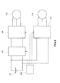
- Fig. 1 is a configuration diagram showing a power supply device for an electric vehicle 10 in Embodiment.
- the power supply device for an electric vehicle 10 includes a main circuit 13, an auxiliary circuit 15, and a control device 16.
- the main circuit 13 has a DC-DC converter 18 and a drive motor inverter 17, and is connected to a power source 11 and a drive motor 12.
- the auxiliary circuit 15 has a connection circuit 30 and a compressor inverter 19, and is connected to a compressor motor 14.
- the drive motor 12 corresponds to the main motor of the present invention
- the drive motor inverter 17 corresponds to the main inverter of the present invention
- the compressor motor 14 corresponds to the auxiliary motor of the present invention
- the compressor inverter 19 corresponds to the auxiliary inverter of the present invention, respectively.
- the auxiliary circuit 15 further has a first electrical circuit 23 and a second electrical circuit 24 for supplying power from the power source 11 to the connection circuit 30.
- the first electrical circuit 23 extends from between the power source 11 and the DC-DC converter 18 (that is, from the primary side of the DC-DC converter 18) to the connection circuit 30.
- the second electrical circuit 24 extends from between the DC-DC converter 18 and the drive motor inverter 17 (that is, from the secondary side of the DC-DC converter 18) to the connection circuit 30.
- the power source 11 is a direct current power source and is capable of being charged and discharged with electric power.
- a secondary battery such as a nickel hydrogen battery and a lithium ion battery can be used as the power source 11.
- a high-capacity capacitor such as an electrical double layer capacitor also can be used as the power source 11.
- the DC-DC converter 18 regulates an output voltage V dc and supplies it to the drive motor inverter 17.
- the output voltage V dc is determined on the basis of the rotational speed and the torque required by the drive motor inverter 17 and the compressor inverter 19, as described later.
- a chopper-type non-isolated boost converter for example, can be used.
- a PWM driving method such as one described in JP 4048787 B2 may be employed.
- the DC-DC converter 18 in which the output voltage V dc varies stepwise may be used.
- the drive motor inverter 17 converts the output voltage V dc that has been stepped up in the DC-DC converter 18 into a desired three-phase AC and supplies it to the drive motor 12.
- a three-phase AC inverter using a semiconductor switching device such as a power MOSFET and IGBT can be used.
- the drive motor 12 is a motor for running of an electric vehicle (an induction motor or a synchronous motor).
- the shaft power of the drive motor 12 is transmitted to the running wheels of the electric vehicle. Further, during braking of the electric vehicle, it is possible to supply power to the power source 11 or the compressor inverter 19 by allowing regenerative operation of the drive motor 12, which functions as a generator.
- a permanent magnet synchronous motor is preferably used as the drive motor 12, for example.
- an interior permanent magnet synchronous motor IPMSM: Interior Permanent Magnet Synchronous Motor
- IPMSM Interior Permanent Magnet Synchronous Motor
- the interior permanent magnet synchronous motor has saliency in which the d-axis inductance Ld and the q-axis inductance Lq are different from each other (generally, inverse saliency of Lq > Ld), and can use reluctance torque in addition to magnet torque. Therefore, the interior permanent magnet synchronous motor exhibits exceptionally high motor efficiency. Furthermore, the drive motor 12 is in regenerative operation during braking of and exhibits exceptionally high generator efficiency during the regenerative operation, as well.
- the compressor inverter 19 converts the direct current voltage supplied from the connection circuit 30 to a desired three-phase AC and supplies it to the compressor motor 14.
- a three-phase AC inverter using a semiconductor switching device such as a power MOSFET and IGBT can be used, for example.
- the compressor motor 14 is a motor for operating a compressor mainly used for indoor air-conditioning of the electric vehicle.
- a compressor motor 14 an induction motor and a synchronous motor such as an interior permanent magnet synchronous motor can be used, for example.
- the control device 16 controls the DC-DC converter 18, the drive motor inverter 17, the compressor inverter 19, and the connection circuit 30.
- a required voltage V main of the drive motor inverter 17 can be easily determined by substitution of values, such as the opening degree of the accelerator (that is, the required torque), the current rotational speed of the drive motor 12, and the device parameter of the drive motor 12, into the voltage equation of the motor.
- a required voltage V comp of the compressor inverter 19 can be easily determined by substitution of values, such as necessary performance (that is, the torque and the rotational speed necessary for compression load) that is calculated from a current room temperature T and a set temperature T ref , the current rotational speed of the compressor motor 14, and the device parameter of the compressor motor 14, into the voltage equation of the motor.
- connection circuit 30 and the boost ratio in the DC-DC converter 18 are controlled on the basis of a power source voltage V batt , the required voltage V main of the drive motor inverter 17, and the required voltage V comp of the compressor inverter 19, as described later.
- a control device 16 a microcomputer or a DSP (digital signal processor) may be used, for example.
- connection circuit 30 selects the first electrical circuit 23 or the second electrical circuit 24 and supplies power to the compressor inverter 19.
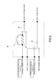
- Fig. 2 is a configuration diagram of the connection circuit 30 in this embodiment.
- the connection circuit 30 has a first switch 32 on the nongrounded side, a second switch 34 on the grounded side, and an inrush limiting resistor 33.
- a single pole double throw switch, for example, may be used for the first switch 32 and the second switch 34.
- the first switch 32 selectively connects one of the electrical circuit on the nongrounded side in the first electrical circuit 23 and the electrical circuit on the nongrounded side in the second electrical circuit 24 to the terminal on the nongrounded side of the compressor inverter 19.
- the second switch 34 selectively connects one of the electrical circuit on the grounded side in the first electrical circuit 23 and the electrical circuit on the grounded side in the second electrical circuit 24 to the terminal on the grounded side of the compressor inverter 19.
- connection circuit 30 is provided with the inrush limiting resistor 33 and a third switch 31 that is a single pole single throw switch in parallel to the inrush limiting resistor 33.
- the inrush limiting resistor 33 is preferably capable of handling high power and may be composed, for example, of a wire wound resistor. Further, the first switch 32, the second switch 34, and the switch 33 also are preferably capable of handling high power. Each switch may be a mechanical switch or a semiconductor switch, or may be composed of a hybrid switch combining them.
- Fig. 3A is a flow chart of the steps performed when a first state where the connection circuit 30 connects between the first electrical circuit 23 and the compressor inverter 19 is switched to a second state where it connects between the second electrical circuit 24 and the compressor inverter 19. In the first state, the third switch 31 is disconnected. Further, the first electrical circuit 23 side is selected by the first switch 32 and the second switch 34.
- step 101 When the first state is transferred to the second state, power supply to the compressor motor 14 by the compressor inverter 19 is first stopped (step 101). Next, the first switch 32 and the second switch 34 are allowed to select the second electrical circuit 24 side (step 102). Next, after a certain time has elapsed from step 102, the third switch 31 is connected (step 103). Finally, power supply to the compressor motor 14 by the compressor inverter 19 is restarted (step 104).
- the third switch 31 is disconnected when the first switch 32 and the second switch 34 are switched from the first electrical circuit 23 side to the second electrical circuit 24 side. This allows an inrush current that has occurred at the time of switching to pass through the inrush limiting resistor 33. That is, the control based on this flow can suppress the inrush current, thereby preventing the compressor inverter 19 from being damaged due to the inrush current.
- control based on the flow shown in Fig. 3B is performed at the time when the connection circuit 30 is switched from the second state to the first state.
- the third switch 31 is connected.
- the second electrical circuit 24 side is selected by the first switch 32 and the second switch 34.
- step 201 When the second state is transferred to the first state, power supply to the compressor motor 14 by the compressor inverter 19 is first stopped (step 201). Next, the first switch 32 and the second switch 34 are allowed to select the first electrical circuit 23 side (step 202). Next, after a certain time has elapsed from step 202, the third switch 31 is disconnected (step 203). Finally, power supply to the compressor motor 14 by the compressor inverter 19 is restarted (step 204).
- step 202 and step 203 are reversed in this flow.
- control device 16 controls the connection circuit 30 and the DC-DC converter 18 on the basis of the running pattern of the electric vehicle and the operation state of the air-conditioning system.
- this control is described with reference to the flow chart of Fig. 4 .
- a target rotational speed of the compressor motor 14 is determined on the basis of the set temperature T ref in the air-conditioning system and the current room temperature T (step 301).
- the required voltage V comp to be supplied to the compressor inverter 19 is determined (step 302).
- the control device 16 can determine the required voltage V comp , for example, by referring to the current rotational speed of the compressor motor 14 and the rotational speed determined in step 301 and then using a voltage equation or a table of the motor in a program stored in the control device 16.
- the required voltage V comp to be supplied to the compressor inverter 19 should be set to a higher value than the effective value of the AC voltage to be supplied to the compressor motor 14.
- step 303 the determined required voltage V comp and the power source voltage V batt are compared to each other.
- connection circuit 30 selects the first electrical circuit 23 (step 304).
- the process proceeds to step 305.
- step 305 the required voltage V comp and the required voltage V main of the drive motor inverter 17 are compared to each other.
- the connection circuit 30 selects the second electrical circuit 24 (step 306).
- the output voltage V dc is regulated so that the output voltage V dc should be equal to the required voltage V comp (step 307).
- the second electrical circuit 24 is selected (step 306).
- Fig. 5 indicates the variation of the output voltage V dc when the running pattern of the electric vehicle (stop/acceleration/deceleration) and the load of the air-conditioning system (low load/intermediate load/high load) are varied.
- period 1 When the electric vehicle starts (acceleration) with the air-conditioning system having a low load, the time proceeds to period 1.
- the required voltage V comp is lower than the power source voltage V batt . Accordingly, the first electrical circuit 23 is selected by the connection circuit 30 (YES in step 303 of Fig. 4 ). Further, the required voltage V main increases as the electric vehicle accelerates.
- the output voltage V dc is not related to the operation of the compressor inverter 19, and determined only by the requirement of the drive motor inverter 17. Accordingly, the output voltage V dc increases following the required voltage V main in period 1.
- the required voltage V main decreases (period 2).
- the required voltage V comp is lower than the power source voltage V batt .
- the first electrical circuit 23 is selected by the connection circuit 30 (YES in step 303 of Fig. 4 ).
- the output voltage V dc decreases following the required voltage V main in period 2.
- connection circuit 30 selects the second electrical circuit 24 at this timing (NO in step 303 and YES in step 305 of Fig. 4 ), and the time proceeds to period 3.
- the output voltage V dc decreases following the required voltage V main in period 3.
- the required voltage V main decreases.
- the required voltage V comp is equal to or higher than the power source voltage V batt . Accordingly, the boost ratio in the DC-DC converter 18 is regulated so that the output voltage V dc should be increased to the voltage V comp (period 4).
- the second electrical circuit 24 is selected by the connection circuit 30 (NO in step 303 and NO in step 305 of Fig. 4 ).
- the time proceeds to period 5.
- the required voltage V comp is equal to or higher than the power source voltage V batt .
- the required voltage V comp is equal to or higher than the required voltage V main . Accordingly, the output voltage V dc is increased to the required voltage V comp .
- the second electrical circuit 24 is selected by the connection circuit 30 (NO in step 303 and NO in step 305 of Fig. 4 ).
- the connection circuit 30 selects the second electrical circuit 24 (NO in step 303 and YES in step 305 of Fig. 4 ), and the time proceeds to period 6.
- the output voltage V dc increases following the required voltage V main in period 6.
- the time proceeds to period 7.
- the required voltage V main decreases, but the required voltage V comp is still lower than the V main .
- the required voltage V comp is equal to or higher than the power source voltage V batt . Accordingly, the second electrical circuit 24 is selected by the connection circuit 30 (NO in step 303 and YES in step 305 of Fig. 4 ).
- the output voltage V dc decreases following the required voltage V main in period 7.
- the required voltage V comp decreases (period 8).
- the required voltage V comp is equal to or higher than the power source voltage V batt .
- the required voltage V main decreases, but the required voltage V comp is still lower than the required voltage V main .
- the second electrical circuit 24 is selected by the connection circuit 30 (NO in step 303 and YES in step 305 of Fig. 4 ).
- the output voltage V dc decreases following the required voltage V main in period 8.
- connection circuit 30 selects the first electrical circuit 23 (YES in step 303 of Fig. 4 ), the time proceeds to period 9.
- the output voltage V dc decreases following the required voltage V main in period 9.
- the required voltage V main decreases to zero (period 10).
- the required voltage V comp is lower than the power source voltage V batt .
- the first electrical circuit 23 is selected by the connection circuit 30 (YES in step 303 of Fig. 4 ).
- the output voltage V dc is equal to the power source voltage V batt (that is, the DC-DC converter 18 is not in boost operation).
- the required voltage V comp increases (period 11).
- the required voltage V comp is equal to or higher than the power source voltage V batt .
- the required voltage V comp is equal to or higher than the required voltage V main . Accordingly, the output voltage V dc is increased to the voltage V comp .
- the second electrical circuit 24 is selected by the connection circuit 30 (NO in step 303 and NO in step 305 of Fig. 4 ).
- the first electrical circuit 23 is selected when the required voltage V comp to be supplied to the compressor inverter 19 is lower than the power source voltage V batt
- the second electrical circuit 24 is selected when the required voltage V comp is equal to or higher than the power source voltage V batt . This allows an appropriate voltage to be supplied to the compressor inverter 19 even when the required voltage V comp to be supplied to the compressor inverter 19 varies.
- the control device 16 controls the DC-DC converter 18 so that the output voltage V dc should be equal to the required voltage V comp in the DC-DC converter 18.
- Such control enables the power supply device for an electric vehicle 10 to supply a necessary voltage to the compressor inverter 19 even when the required voltage V comp to be supplied to the compressor inverter 19 increases.
- the output voltage V dc is set to be equal to or higher than both the required voltage V main and the required voltage V comp , as shown in Fig. 5 .
- This is intended to secure a minimum voltage to be supplied to each of the drive motor 12 and the compressor motor 14.
- it also is possible to provide certain margins ⁇ V1 and ⁇ V2 (for example, 2 to 3V) for the required voltage V main and the required voltage V comp , in order to allow stable operation of the drive motor 12 and the compressor motor 14.
- the respective voltages to be supplied to the drive motor 12 and the compressor motor 14 are made higher than the minimum voltages to be supplied, so that the drive motor 12 and the compressor motor 14 can be stably operated.
- connection circuit 30 it also is possible to connect both the electrical circuit on the grounded side in the first electrical circuit 23 and the electrical circuit on the grounded side in the second electrical circuit 24 to the terminal on the grounded side of the compressor inverter 19 on a constant basis, without providing the second switch 34 of the connection circuit 30.
- the inrush limiting resistor 33 may be omitted when the inrush current is sufficiently low.
- the power supply device for an electric vehicle 10 of Modified embodiment can efficiently supply power obtained by the drive motor 12 functioning as a generator through braking operation (regenerative operation) to the compressor inverter 19, as described later.
- the same components as those in Embodiment are denoted by the same reference numerals, and the descriptions thereof are omitted.
- the power supply device for an electric vehicle 10 of Modified embodiment has a configuration with a different connection circuit as compared to Embodiment.
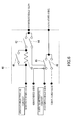
- Fig. 6 shows the configuration of a connection circuit 40 in Modified embodiment.
- All the switches included in the connection circuit 40 each are a single pole single throw switch.
- a fourth switch 42 connects or disconnects between the electrical circuit on the nongrounded side in the second electrical circuit 24 and the terminal on the nongrounded side of the compressor inverter 19.
- a fifth switch 44 connects or disconnects between the electrical circuit on the nongrounded side in the first electrical circuit 23 and the terminal on the nongrounded side of the compressor inverter 19.
- a sixth switch 45 connects or disconnects between the electrical circuit on the grounded side in the second electrical circuit 24 and the terminal on the grounded side of the compressor inverter 19.
- a seventh switch 46 connects or disconnects between the electrical circuit on the grounded side in the first electrical circuit 23 and the terminal on the grounded side of the compressor inverter 19.
- an eighth switch 41 and an inrush limiting resistor 43 respectively correspond to the third switch 31 and the inrush limiting resistor 33 of Embodiment, and their functions also are the same as those in Embodiment.
- Fig. 7A is a flow chart of the steps performed when a first state where the connection circuit 40 connects between the first electrical circuit 23 and the compressor inverter 19 is switched to a second state where it connects between the second electrical circuit 24 and the compressor inverter 19.
- the eighth switch 41 is disconnected.
- the fourth switch 42 and the sixth switch 45 are disconnected, while the fifth switch 44 and the seventh switch 46 are connected.
- the fourth switch 42 and the sixth switch 45 each are first connected (step 401). After a certain time has elapsed from step 401, the fifth switch 44 and the seventh switch 46 each are disconnected (step 402). Then, the eighth switch 41 is connected (step 403).
- connection circuit 40 of this configuration based on the flow chart of Fig. 7 , at least one of the first electrical circuit 23 and the second electrical circuit 24 is connected to the compressor inverter 19 on a constant basis.
- the compressor motor 14 is supplied with a voltage at any time. This enables switching from the first electrical circuit 23 to the second electrical circuit 24 without stopping the operation of the compressor motor 14.
- the inrush limiting resistor 43 suppresses an inrush current in the same manner as the inrush limiting resistor 33.
- connection circuit 40 When the connection circuit 40 is switched from the second state to the first state, the control based on the flow of Fig. 7B is performed. In the second state, the eighth switch 41 is connected. Further, the fourth switch 42 and the sixth switch 45 each are connected, while the fifth switch 44 and the seventh switch 46 each are disconnected.
- the eighth switch 41 is first disconnected (step 501). Then, the fifth switch 44 and the seventh switch 46 each are connected (step 502). After a certain time has elapsed from step 502, the fourth switch 42 and the sixth switch 45 each are disconnected (step 503).
- At least one of the first electrical circuit 23 and the second electrical circuit 24 is connected to the compressor inverter 19 on a constant basis, and therefore it is possible to switch the second electrical circuit 24 to the first electrical circuit 23 without stopping power supply to the compressor motor 14.
- Steps 601 to 603 and steps 605 to 607 in the flow of Fig. 8 correspond to steps 301 to 303 and steps 305 to 307 in the flow of Fig. 4 .
- steps 604, 608 and 609 that are different from those in the flow of Fig. 4 are described.
- step 603 when the required voltage V comp is lower than the power source voltage V batt , the process proceeds to step 608.
- step 608 whether or not the drive motor 12 is in braking operation is determined. In the case where the drive motor 12 is in braking (regenerative) operation, the connection circuit 40 selects the second electrical circuit 24 (step 609). On the other hand, in the case where the drive motor 12 is not in braking operation but in power running operation, the connection circuit 40 selects the first electrical circuit 23 (step 604).
- period 1 When the electric vehicle starts (acceleration) with the air-conditioning system having a low load, the time proceeds to period 1.
- the required voltage V comp is lower than the power source voltage V batt .
- the electric vehicle is not in braking operation. Accordingly, the first electrical circuit 23 is selected by the connection circuit 40 (YES in step 603 and NO in step 608 of Fig. 8 ).
- the required voltage V main of the drive motor inverter 17 increases.
- the output voltage V dc is not related to the operation of the compressor inverter 19, and determined only by the requirement of the drive motor inverter 17. Accordingly, the output voltage V dc increases following the required voltage V main in period 1.
- the connection circuit 40 selects the second electrical circuit 24 (YES in step 603 and YES in step 608 of Fig. 8 ), and supplies power obtained from the drive motor 12 to the compressor inverter 19 via the second electrical circuit 24 (regenerative operation).
- the output voltage V dc decreases following the required voltage V main in period 2.
- connection circuit 40 selects the second electrical circuit 24 (YES in step 603 and YES in step 608 of Fig. 8 ), and supplies power obtained from the drive motor 12 to the compressor inverter 19 via the second electrical circuit 24 (regenerative operation)(period 9).
- the output voltage V dc decreases following the required voltage V main in period 9.
- the required voltage V main decreases to zero (period 10).
- the required voltage V comp is lower than the power source voltage V batt .
- the electric vehicle is not in braking operation. Accordingly, the first electrical circuit 23 is selected by the connection circuit 40 (YES in step 603 and NO in step 608 of Fig. 8 ).
- the output voltage V dc is equal to the power source voltage V batt in period 10.
- Such control as described above enables the power supply device for an electric vehicle 10 to supply a necessary voltage to the compressor inverter 19 even when the required voltage V comp to be supplied to the compressor inverter 19 increases.
- the power supply device for an electric vehicle 10 can supply an appropriate voltage to the compressor inverter 19 even when the required voltage V comp to be supplied to the compressor inverter 19 varies.
- the power supply device for an electric vehicle 10 in this embodiment selects the second state in the connection circuit 40 during braking operation (regenerative operation). This makes it possible to supply power (regenerative power) obtained from the drive motor 12 to the compressor inverter 19 without the intermediation of the DC-DC converter 18. Accordingly, the regenerative power losses in the DC-DC converter 18 can be eliminated.
- connection circuit 40 of Modified embodiment is different from the configuration of the connection circuit 30 of Embodiment, it is possible to perform such control including regenerative operation also in the configuration of the connection circuit 30 of Embodiment, as in Modified embodiment.
- frequent switching between power running operation and regenerative operation may be needed in some cases, depending on the running state of the electric vehicle.
- the connection circuit 40 is employed, the need to stop power supply to the compressor inverter 19 in switching can be eliminated, which allows continuous operation of the compressor motor 14. Accordingly, in the case of performing such control including regenerative operation as in Modified embodiment, the connection circuit 40 as one in Modified embodiment is preferably employed.
- the present invention can be applied to electric power systems in hybrid vehicles and electrical drive vehicles that use a motor as a power source. Furthermore, the present invention can be applied to other electric power systems.
Landscapes
- Engineering & Computer Science (AREA)
- Power Engineering (AREA)
- Mechanical Engineering (AREA)
- Transportation (AREA)
- Sustainable Energy (AREA)
- Sustainable Development (AREA)
- Life Sciences & Earth Sciences (AREA)
- Physics & Mathematics (AREA)
- Thermal Sciences (AREA)
- Electric Propulsion And Braking For Vehicles (AREA)
- Air-Conditioning For Vehicles (AREA)
- Dc-Dc Converters (AREA)
- Inverter Devices (AREA)
Applications Claiming Priority (2)
| Application Number | Priority Date | Filing Date | Title |
|---|---|---|---|
| JP2010143300 | 2010-06-24 | ||
| PCT/JP2011/003493 WO2011161925A1 (ja) | 2010-06-24 | 2011-06-20 | 電気自動車用電力供給装置 |
Publications (3)
| Publication Number | Publication Date |
|---|---|
| EP2586643A1 true EP2586643A1 (de) | 2013-05-01 |
| EP2586643A4 EP2586643A4 (de) | 2017-02-22 |
| EP2586643B1 EP2586643B1 (de) | 2018-01-03 |
Family
ID=45371132
Family Applications (1)
| Application Number | Title | Priority Date | Filing Date |
|---|---|---|---|
| EP11797814.8A Active EP2586643B1 (de) | 2010-06-24 | 2011-06-20 | Stromversorgungsvorrichtung für ein elektrofahrzeug |
Country Status (5)
| Country | Link |
|---|---|
| US (1) | US8736218B2 (de) |
| EP (1) | EP2586643B1 (de) |
| JP (1) | JP5662410B2 (de) |
| CN (1) | CN102470759B (de) |
| WO (1) | WO2011161925A1 (de) |
Cited By (1)
| Publication number | Priority date | Publication date | Assignee | Title |
|---|---|---|---|---|
| CN105501065A (zh) * | 2014-09-26 | 2016-04-20 | 中车大连电力牵引研发中心有限公司 | 地铁车辆辅助供电系统 |
Families Citing this family (8)
| Publication number | Priority date | Publication date | Assignee | Title |
|---|---|---|---|---|
| JP5847022B2 (ja) * | 2012-06-11 | 2016-01-20 | 三菱電機株式会社 | 空気調和機、およびそのインターリーブ制御方法 |
| KR101428188B1 (ko) * | 2012-09-13 | 2014-08-07 | 현대자동차주식회사 | 전기 버스 보조 인버터 과전류 소손 방지 방법 |
| ES2638186T3 (es) | 2013-03-27 | 2017-10-19 | Abb Technology Ag | Inversor de accionamiento compartido por diferentes motores en un vehículo |
| CN104118331B (zh) * | 2013-04-28 | 2016-08-10 | 西门子公司 | 混合动力汽车电机驱动电路 |
| JP6240407B2 (ja) * | 2013-05-16 | 2017-11-29 | 日本車輌製造株式会社 | バッテリ式キャリア |
| CN107809162B (zh) * | 2016-08-29 | 2019-11-05 | 台达电子企业管理(上海)有限公司 | 变换器串并联系统及其控制方法 |
| CN112004712A (zh) * | 2018-04-20 | 2020-11-27 | 西门子股份公司 | 充电基础设施单元和具有充电功率选项的充电基础设施 |
| US20240162845A1 (en) | 2021-03-22 | 2024-05-16 | Fanuc Corporation | Motor control device |
Family Cites Families (17)
| Publication number | Priority date | Publication date | Assignee | Title |
|---|---|---|---|---|
| CA1153770A (en) | 1978-07-20 | 1983-09-13 | Salvatore J. Monte | Cumylphenol derivatives |
| JPH0448787A (ja) | 1990-06-15 | 1992-02-18 | Nec Corp | 反射型光半導体センサ |
| JP3524661B2 (ja) * | 1995-12-08 | 2004-05-10 | 本田技研工業株式会社 | 電動車両の電源制御装置 |
| US7164253B2 (en) | 2001-08-02 | 2007-01-16 | Toyota Jidosha Kabushiki Kaisha | Motor drive control apparatus |
| US6917179B2 (en) * | 2001-10-25 | 2005-07-12 | Toyota Jidosha Kabushiki Kaisha | Load driver and control method for safely driving DC load and computer-readable recording medium with program recorded thereon for allowing computer to execute the control |
| JP3879528B2 (ja) | 2002-02-14 | 2007-02-14 | トヨタ自動車株式会社 | 電圧変換装置 |
| JP4048787B2 (ja) | 2002-01-30 | 2008-02-20 | トヨタ自動車株式会社 | 負荷駆動装置 |
| JP4193704B2 (ja) * | 2004-01-20 | 2008-12-10 | トヨタ自動車株式会社 | 電源装置およびそれを搭載する自動車 |
| JP2006050779A (ja) * | 2004-08-04 | 2006-02-16 | Toyota Motor Corp | モータ駆動装置 |
| JP4245624B2 (ja) | 2006-09-20 | 2009-03-25 | トヨタ自動車株式会社 | ハイブリッド車両の電源制御装置および電源制御方法 |
| JP2008125160A (ja) * | 2006-11-08 | 2008-05-29 | Toyota Motor Corp | 電源装置、電源装置を備える車両、電源装置の制御方法 |
| JP5118913B2 (ja) * | 2007-07-24 | 2013-01-16 | トヨタ自動車株式会社 | 電源システムおよびそれを備えた電動車両ならびに電源システムの制御方法 |
| JP2009142010A (ja) * | 2007-12-04 | 2009-06-25 | Toyota Motor Corp | 駆動装置およびこれを備える動力出力装置 |
| JP4315232B1 (ja) * | 2008-03-17 | 2009-08-19 | トヨタ自動車株式会社 | 電動車両 |
| JP2009254209A (ja) * | 2008-04-10 | 2009-10-29 | Toyota Motor Corp | 電源制御システム |
| US8274173B2 (en) * | 2008-12-02 | 2012-09-25 | General Electric Company | Auxiliary drive apparatus and method of manufacturing same |
| JP5359637B2 (ja) * | 2009-07-17 | 2013-12-04 | 富士電機株式会社 | 電力変換装置 |
-
2011
- 2011-06-20 US US13/387,600 patent/US8736218B2/en active Active
- 2011-06-20 WO PCT/JP2011/003493 patent/WO2011161925A1/ja active Application Filing
- 2011-06-20 EP EP11797814.8A patent/EP2586643B1/de active Active
- 2011-06-20 JP JP2012501062A patent/JP5662410B2/ja active Active
- 2011-06-20 CN CN201180003055.2A patent/CN102470759B/zh active Active
Non-Patent Citations (1)
| Title |
|---|
| See references of WO2011161925A1 * |
Cited By (1)
| Publication number | Priority date | Publication date | Assignee | Title |
|---|---|---|---|---|
| CN105501065A (zh) * | 2014-09-26 | 2016-04-20 | 中车大连电力牵引研发中心有限公司 | 地铁车辆辅助供电系统 |
Also Published As
| Publication number | Publication date |
|---|---|
| US20120119683A1 (en) | 2012-05-17 |
| JP5662410B2 (ja) | 2015-01-28 |
| EP2586643B1 (de) | 2018-01-03 |
| JPWO2011161925A1 (ja) | 2013-08-19 |
| US8736218B2 (en) | 2014-05-27 |
| WO2011161925A1 (ja) | 2011-12-29 |
| CN102470759A (zh) | 2012-05-23 |
| CN102470759B (zh) | 2015-04-01 |
| EP2586643A4 (de) | 2017-02-22 |
Similar Documents
| Publication | Publication Date | Title |
|---|---|---|
| EP2586643B1 (de) | Stromversorgungsvorrichtung für ein elektrofahrzeug | |
| US10148212B2 (en) | DC to DC converter sourcing variable DC link voltage | |
| EP2689944B1 (de) | Kühlsystem für Transportzwecke | |
| JP5571792B2 (ja) | 燃料電池システムのコールドスタート方法及び自動車の燃料電池システム | |
| EP3434508A1 (de) | Elektrische systemarchitektur für bereichserweiterte elektrische fahrzeuge | |
| US9024598B2 (en) | Converter control device | |
| WO2011046147A1 (ja) | 車両用電源システム | |
| CN110707768B (zh) | 充电控制设备和充电控制系统 | |
| EP3576273A1 (de) | Gleichstromumwandlungseinheit | |
| US11018605B2 (en) | DC to DC voltage converter and voltage converter control scheme | |
| EP3576275A1 (de) | Gleichstromumsetzungseinheit | |
| KR101835742B1 (ko) | 이중 배터리 패키지 및 이의 작동방법 | |
| JP2013013171A (ja) | 燃料電池システム | |
| US11046191B2 (en) | Drive system and drive control method | |
| US20100321968A1 (en) | Load fault handling for switched reluctance or induction type machines | |
| EP2937969A1 (de) | Stromversorgungsvorrichtung | |
| JP4950162B2 (ja) | 車両用電源装置 | |
| JP5391677B2 (ja) | ヒートポンプ式空気調和装置の室外機 | |
| KR102435344B1 (ko) | 친환경 차량의 배터리 시스템 및 그 제어방법 | |
| JP2021052575A (ja) | 電力システム | |
| JP2012100436A (ja) | 車両用電源システム | |
| KR101686864B1 (ko) | 이중 배터리 패키지 | |
| WO2024053424A1 (ja) | 電力変換装置、プログラム | |
| JP5241761B2 (ja) | 車両用電源システム | |
| JP6787271B2 (ja) | 電源システム |
Legal Events
| Date | Code | Title | Description |
|---|---|---|---|
| PUAI | Public reference made under article 153(3) epc to a published international application that has entered the european phase |
Free format text: ORIGINAL CODE: 0009012 |
|
| 17P | Request for examination filed |
Effective date: 20130124 |
|
| AK | Designated contracting states |
Kind code of ref document: A1 Designated state(s): AL AT BE BG CH CY CZ DE DK EE ES FI FR GB GR HR HU IE IS IT LI LT LU LV MC MK MT NL NO PL PT RO RS SE SI SK SM TR |
|
| DAX | Request for extension of the european patent (deleted) | ||
| RAP1 | Party data changed (applicant data changed or rights of an application transferred) |
Owner name: PANASONIC INTELLECTUAL PROPERTY MANAGEMENT CO., LT |
|
| RA4 | Supplementary search report drawn up and despatched (corrected) |
Effective date: 20170124 |
|
| RIC1 | Information provided on ipc code assigned before grant |
Ipc: B60L 11/18 20060101ALI20170116BHEP Ipc: B60L 1/02 20060101AFI20170116BHEP Ipc: B60H 1/00 20060101ALI20170116BHEP Ipc: B60L 1/00 20060101ALI20170116BHEP Ipc: B60H 1/22 20060101ALI20170116BHEP Ipc: H02J 1/10 20060101ALI20170116BHEP Ipc: H02P 27/08 20060101ALI20170116BHEP Ipc: H02J 7/00 20060101ALI20170116BHEP |
|
| GRAP | Despatch of communication of intention to grant a patent |
Free format text: ORIGINAL CODE: EPIDOSNIGR1 |
|
| STAA | Information on the status of an ep patent application or granted ep patent |
Free format text: STATUS: GRANT OF PATENT IS INTENDED |
|
| INTG | Intention to grant announced |
Effective date: 20170717 |
|
| GRAS | Grant fee paid |
Free format text: ORIGINAL CODE: EPIDOSNIGR3 |
|
| GRAA | (expected) grant |
Free format text: ORIGINAL CODE: 0009210 |
|
| STAA | Information on the status of an ep patent application or granted ep patent |
Free format text: STATUS: THE PATENT HAS BEEN GRANTED |
|
| AK | Designated contracting states |
Kind code of ref document: B1 Designated state(s): AL AT BE BG CH CY CZ DE DK EE ES FI FR GB GR HR HU IE IS IT LI LT LU LV MC MK MT NL NO PL PT RO RS SE SI SK SM TR |
|
| REG | Reference to a national code |
Ref country code: GB Ref legal event code: FG4D |
|
| REG | Reference to a national code |
Ref country code: CH Ref legal event code: EP Ref country code: AT Ref legal event code: REF Ref document number: 959890 Country of ref document: AT Kind code of ref document: T Effective date: 20180115 |
|
| REG | Reference to a national code |
Ref country code: IE Ref legal event code: FG4D |
|
| REG | Reference to a national code |
Ref country code: DE Ref legal event code: R096 Ref document number: 602011044764 Country of ref document: DE |
|
| REG | Reference to a national code |
Ref country code: NL Ref legal event code: MP Effective date: 20180103 |
|
| REG | Reference to a national code |
Ref country code: LT Ref legal event code: MG4D |
|
| REG | Reference to a national code |
Ref country code: AT Ref legal event code: MK05 Ref document number: 959890 Country of ref document: AT Kind code of ref document: T Effective date: 20180103 |
|
| PG25 | Lapsed in a contracting state [announced via postgrant information from national office to epo] |
Ref country code: NL Free format text: LAPSE BECAUSE OF FAILURE TO SUBMIT A TRANSLATION OF THE DESCRIPTION OR TO PAY THE FEE WITHIN THE PRESCRIBED TIME-LIMIT Effective date: 20180103 |
|
| PG25 | Lapsed in a contracting state [announced via postgrant information from national office to epo] |
Ref country code: ES Free format text: LAPSE BECAUSE OF FAILURE TO SUBMIT A TRANSLATION OF THE DESCRIPTION OR TO PAY THE FEE WITHIN THE PRESCRIBED TIME-LIMIT Effective date: 20180103 Ref country code: FI Free format text: LAPSE BECAUSE OF FAILURE TO SUBMIT A TRANSLATION OF THE DESCRIPTION OR TO PAY THE FEE WITHIN THE PRESCRIBED TIME-LIMIT Effective date: 20180103 Ref country code: LT Free format text: LAPSE BECAUSE OF FAILURE TO SUBMIT A TRANSLATION OF THE DESCRIPTION OR TO PAY THE FEE WITHIN THE PRESCRIBED TIME-LIMIT Effective date: 20180103 Ref country code: CY Free format text: LAPSE BECAUSE OF FAILURE TO SUBMIT A TRANSLATION OF THE DESCRIPTION OR TO PAY THE FEE WITHIN THE PRESCRIBED TIME-LIMIT Effective date: 20180103 Ref country code: NO Free format text: LAPSE BECAUSE OF FAILURE TO SUBMIT A TRANSLATION OF THE DESCRIPTION OR TO PAY THE FEE WITHIN THE PRESCRIBED TIME-LIMIT Effective date: 20180403 Ref country code: HR Free format text: LAPSE BECAUSE OF FAILURE TO SUBMIT A TRANSLATION OF THE DESCRIPTION OR TO PAY THE FEE WITHIN THE PRESCRIBED TIME-LIMIT Effective date: 20180103 |
|
| PG25 | Lapsed in a contracting state [announced via postgrant information from national office to epo] |
Ref country code: IS Free format text: LAPSE BECAUSE OF FAILURE TO SUBMIT A TRANSLATION OF THE DESCRIPTION OR TO PAY THE FEE WITHIN THE PRESCRIBED TIME-LIMIT Effective date: 20180503 Ref country code: BG Free format text: LAPSE BECAUSE OF FAILURE TO SUBMIT A TRANSLATION OF THE DESCRIPTION OR TO PAY THE FEE WITHIN THE PRESCRIBED TIME-LIMIT Effective date: 20180403 Ref country code: AT Free format text: LAPSE BECAUSE OF FAILURE TO SUBMIT A TRANSLATION OF THE DESCRIPTION OR TO PAY THE FEE WITHIN THE PRESCRIBED TIME-LIMIT Effective date: 20180103 Ref country code: PL Free format text: LAPSE BECAUSE OF FAILURE TO SUBMIT A TRANSLATION OF THE DESCRIPTION OR TO PAY THE FEE WITHIN THE PRESCRIBED TIME-LIMIT Effective date: 20180103 Ref country code: RS Free format text: LAPSE BECAUSE OF FAILURE TO SUBMIT A TRANSLATION OF THE DESCRIPTION OR TO PAY THE FEE WITHIN THE PRESCRIBED TIME-LIMIT Effective date: 20180103 Ref country code: SE Free format text: LAPSE BECAUSE OF FAILURE TO SUBMIT A TRANSLATION OF THE DESCRIPTION OR TO PAY THE FEE WITHIN THE PRESCRIBED TIME-LIMIT Effective date: 20180103 Ref country code: LV Free format text: LAPSE BECAUSE OF FAILURE TO SUBMIT A TRANSLATION OF THE DESCRIPTION OR TO PAY THE FEE WITHIN THE PRESCRIBED TIME-LIMIT Effective date: 20180103 Ref country code: GR Free format text: LAPSE BECAUSE OF FAILURE TO SUBMIT A TRANSLATION OF THE DESCRIPTION OR TO PAY THE FEE WITHIN THE PRESCRIBED TIME-LIMIT Effective date: 20180404 |
|
| REG | Reference to a national code |
Ref country code: DE Ref legal event code: R097 Ref document number: 602011044764 Country of ref document: DE |
|
| PG25 | Lapsed in a contracting state [announced via postgrant information from national office to epo] |
Ref country code: IT Free format text: LAPSE BECAUSE OF FAILURE TO SUBMIT A TRANSLATION OF THE DESCRIPTION OR TO PAY THE FEE WITHIN THE PRESCRIBED TIME-LIMIT Effective date: 20180103 Ref country code: EE Free format text: LAPSE BECAUSE OF FAILURE TO SUBMIT A TRANSLATION OF THE DESCRIPTION OR TO PAY THE FEE WITHIN THE PRESCRIBED TIME-LIMIT Effective date: 20180103 Ref country code: RO Free format text: LAPSE BECAUSE OF FAILURE TO SUBMIT A TRANSLATION OF THE DESCRIPTION OR TO PAY THE FEE WITHIN THE PRESCRIBED TIME-LIMIT Effective date: 20180103 Ref country code: AL Free format text: LAPSE BECAUSE OF FAILURE TO SUBMIT A TRANSLATION OF THE DESCRIPTION OR TO PAY THE FEE WITHIN THE PRESCRIBED TIME-LIMIT Effective date: 20180103 |
|
| PLBE | No opposition filed within time limit |
Free format text: ORIGINAL CODE: 0009261 |
|
| STAA | Information on the status of an ep patent application or granted ep patent |
Free format text: STATUS: NO OPPOSITION FILED WITHIN TIME LIMIT |
|
| PG25 | Lapsed in a contracting state [announced via postgrant information from national office to epo] |
Ref country code: DK Free format text: LAPSE BECAUSE OF FAILURE TO SUBMIT A TRANSLATION OF THE DESCRIPTION OR TO PAY THE FEE WITHIN THE PRESCRIBED TIME-LIMIT Effective date: 20180103 Ref country code: SM Free format text: LAPSE BECAUSE OF FAILURE TO SUBMIT A TRANSLATION OF THE DESCRIPTION OR TO PAY THE FEE WITHIN THE PRESCRIBED TIME-LIMIT Effective date: 20180103 Ref country code: SK Free format text: LAPSE BECAUSE OF FAILURE TO SUBMIT A TRANSLATION OF THE DESCRIPTION OR TO PAY THE FEE WITHIN THE PRESCRIBED TIME-LIMIT Effective date: 20180103 Ref country code: CZ Free format text: LAPSE BECAUSE OF FAILURE TO SUBMIT A TRANSLATION OF THE DESCRIPTION OR TO PAY THE FEE WITHIN THE PRESCRIBED TIME-LIMIT Effective date: 20180103 |
|
| 26N | No opposition filed |
Effective date: 20181005 |
|
| REG | Reference to a national code |
Ref country code: CH Ref legal event code: PL |
|
| GBPC | Gb: european patent ceased through non-payment of renewal fee |
Effective date: 20180620 |
|
| PG25 | Lapsed in a contracting state [announced via postgrant information from national office to epo] |
Ref country code: SI Free format text: LAPSE BECAUSE OF FAILURE TO SUBMIT A TRANSLATION OF THE DESCRIPTION OR TO PAY THE FEE WITHIN THE PRESCRIBED TIME-LIMIT Effective date: 20180103 |
|
| REG | Reference to a national code |
Ref country code: BE Ref legal event code: MM Effective date: 20180630 |
|
| REG | Reference to a national code |
Ref country code: IE Ref legal event code: MM4A |
|
| PG25 | Lapsed in a contracting state [announced via postgrant information from national office to epo] |
Ref country code: MC Free format text: LAPSE BECAUSE OF FAILURE TO SUBMIT A TRANSLATION OF THE DESCRIPTION OR TO PAY THE FEE WITHIN THE PRESCRIBED TIME-LIMIT Effective date: 20180103 Ref country code: LU Free format text: LAPSE BECAUSE OF NON-PAYMENT OF DUE FEES Effective date: 20180620 |
|
| PG25 | Lapsed in a contracting state [announced via postgrant information from national office to epo] |
Ref country code: GB Free format text: LAPSE BECAUSE OF NON-PAYMENT OF DUE FEES Effective date: 20180620 Ref country code: FR Free format text: LAPSE BECAUSE OF NON-PAYMENT OF DUE FEES Effective date: 20180630 Ref country code: IE Free format text: LAPSE BECAUSE OF NON-PAYMENT OF DUE FEES Effective date: 20180620 Ref country code: LI Free format text: LAPSE BECAUSE OF NON-PAYMENT OF DUE FEES Effective date: 20180630 Ref country code: CH Free format text: LAPSE BECAUSE OF NON-PAYMENT OF DUE FEES Effective date: 20180630 |
|
| PG25 | Lapsed in a contracting state [announced via postgrant information from national office to epo] |
Ref country code: BE Free format text: LAPSE BECAUSE OF NON-PAYMENT OF DUE FEES Effective date: 20180630 |
|
| PG25 | Lapsed in a contracting state [announced via postgrant information from national office to epo] |
Ref country code: MT Free format text: LAPSE BECAUSE OF NON-PAYMENT OF DUE FEES Effective date: 20180620 |
|
| PG25 | Lapsed in a contracting state [announced via postgrant information from national office to epo] |
Ref country code: TR Free format text: LAPSE BECAUSE OF FAILURE TO SUBMIT A TRANSLATION OF THE DESCRIPTION OR TO PAY THE FEE WITHIN THE PRESCRIBED TIME-LIMIT Effective date: 20180103 |
|
| PG25 | Lapsed in a contracting state [announced via postgrant information from national office to epo] |
Ref country code: PT Free format text: LAPSE BECAUSE OF FAILURE TO SUBMIT A TRANSLATION OF THE DESCRIPTION OR TO PAY THE FEE WITHIN THE PRESCRIBED TIME-LIMIT Effective date: 20180103 Ref country code: HU Free format text: LAPSE BECAUSE OF FAILURE TO SUBMIT A TRANSLATION OF THE DESCRIPTION OR TO PAY THE FEE WITHIN THE PRESCRIBED TIME-LIMIT; INVALID AB INITIO Effective date: 20110620 |
|
| PG25 | Lapsed in a contracting state [announced via postgrant information from national office to epo] |
Ref country code: MK Free format text: LAPSE BECAUSE OF NON-PAYMENT OF DUE FEES Effective date: 20180103 |
|
| PGFP | Annual fee paid to national office [announced via postgrant information from national office to epo] |
Ref country code: DE Payment date: 20221215 Year of fee payment: 13 |
|
| REG | Reference to a national code |
Ref country code: DE Ref legal event code: R081 Ref document number: 602011044764 Country of ref document: DE Owner name: PANASONIC AUTOMOTIVE SYSTEMS CO., LTD., YOKOHA, JP Free format text: FORMER OWNER: PANASONIC INTELLECTUAL PROPERTY MANAGEMENT CO., LTD., OSAKA, JP |