EP2586571A2 - Setzgerät - Google Patents
Setzgerät Download PDFInfo
- Publication number
- EP2586571A2 EP2586571A2 EP20120007044 EP12007044A EP2586571A2 EP 2586571 A2 EP2586571 A2 EP 2586571A2 EP 20120007044 EP20120007044 EP 20120007044 EP 12007044 A EP12007044 A EP 12007044A EP 2586571 A2 EP2586571 A2 EP 2586571A2
- Authority
- EP
- European Patent Office
- Prior art keywords
- contact arm
- leading end
- nose portion
- end portion
- nose
- Prior art date
- Legal status (The legal status is an assumption and is not a legal conclusion. Google has not performed a legal analysis and makes no representation as to the accuracy of the status listed.)
- Granted
Links
Images









Classifications
-
- B—PERFORMING OPERATIONS; TRANSPORTING
- B25—HAND TOOLS; PORTABLE POWER-DRIVEN TOOLS; MANIPULATORS
- B25C—HAND-HELD NAILING OR STAPLING TOOLS; MANUALLY OPERATED PORTABLE STAPLING TOOLS
- B25C1/00—Hand-held nailing tools; Nail feeding devices
- B25C1/008—Safety devices
Definitions
- the present invention relates to a driving tool.
- a driving tool including a contact arm has been known.
- the contact arm is slidable with respect to a nose portion of the driving tool.
- a leading end portion of the contact arm is urged by a spring or the like so as to protrude in a driving direction of a fastener so that a leading end portion of the contact arm is easily pressed against a work-piece.
- the leading end portion protrudes forward more than a leading end of the nose portion.
- the other end portion of the contact arm is indirectly or directly engaged with a trigger mechanism for operating the driving tool.
- the contact arm When the leading end portion of the contact arm is pressed against the work-piece, the contact arm is pushed in a direction opposite to the driving direction of the fastener, and the other end portion of the contact arm acts on the trigger mechanism, so that an operation of the trigger becomes effective. That is, by actions that the leading end portion of the contact arm is pressed against the work-piece and the trigger is operated, a driving of the fastener is performed. In other words, even though the trigger is operated in a state in which the leading end portion of the contact arm is not pressed against the work-piece, the driving of the fastener is not performed.
- Patent Document 1 there is disclosed a wire-rod type contact arm which is made of a wire rod.
- a lightweight and inexpensive contact arm is advantageously manufactured.
- the contact arm protrudes forward further than the leading end face of the nose portion, the contact arm is likely to be deformed if it collides on a concrete surface or the like at the time of falling.
- the wire-rod type contact arm is likely to be deformed.
- One or more embodiments of the invention provide a driving tool which can effectively suppress a deformation of a wire-rod type contact arm.
- a driving tool may include a nose portion 16 that guides a fastener, and a contact arm 20 which is slidable along the nose portion 16.
- the contact arm 20 may include a U-type leading end portion 20a in which a wire rod is bent in a surface intersecting to a driving direction of the fastener.
- the nose portion 16 and the contact arm 20 may be arranged such that a leading end of the nose portion 16 is placed inside of a U-type part of the leading end portion 20a of the contact arm 20 by a sliding of the contact arm 20 toward a base end of the nose portion.
- the leading end portion of the nose portion 16 may be provided with a receiving portion 22, 23 by which a load applied to the contact arm is received.
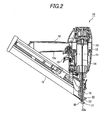
- a driving tool 10 includes a body housing 11 accommodating a driving cylinder 13 therein, a grip housing 12 connected to a rear portion of the body housing 11, and a driving piston 15 slidably accommodated in the driving cylinder 13 and coupled to a bottom side of a driver 14 for driving a nail.
- a nose portion 16 is attached to a lower portion of the body housing 11, and is provided with an ejection port 17 for driving and guiding a fastener toward a work-piece.
- the driver 14 coupled to the driving piston 15 is slidably accommodated and guided in the nose portion 16.
- a magazine 18 loaded with a plurality of fasteners is connected to a rear side of the nose portion 16, and the fasteners in the magazine 18 are sequentially fed to the nose portion 16.
- the nail fed to the nose portion 16 is driven by the driver 14, and is driven out from the ejection port 17 to the work-piece.
- a trigger 19 is disposed on a base portion of a grip portion 12a, and a plug for connecting a compressed-air supply hose is installed at a rear end of the grip portion 12a. Compressed air fed from the plug passes through the inside of the grip portion 12a by operation of the trigger 19, and then is supplied to the driving cylinder 13. In this way, the driving cylinder 15 is slid to operate the driver 14, thereby driving the fastener.
- a contact arm 20 which is slid along the nose portion 16 is installed in the vicinity of the nose portion 16.
- the contact arm 20 is pressed by a spring, so that a leading end portion 20a thereof protrudes forward further than a leading end face of the nose portion 16.
- the other end portion of the contact arm 20 is indirectly or directly engaged with a trigger mechanism which is operated by manipulation of the trigger 19.
- the contact arm 20 If the leading end portion 20a of the contact arm 20 is pressed against the work-piece, the contact arm 20 is pushed in a direction opposite to a driving direction of the fastener, and the other end portion of the contact arm 20 acts on the trigger mechanism, so that operation of the trigger 19 becomes effective. That is, in the state in which the leading end portion 20a of the contact arm 20 is pressed against the work-piece, the trigger 19 is operated, so that driving of the fastener is performed. In other words, even though the trigger 19 is operated in the state in which the leading end portion 20a of the contact arm 20 is not pressed against the work-piece, the driving of the fastener is not performed.
- the trigger 19 may be operated after the leading end portion 20a of the contact arm 20 is pressed against the work-piece, or the leading end portion 20a of the contact arm 20 may be pressed against the work-piece in the state in which the trigger 19 is operated.
- the driving of the fastener is performed only when two signs of the contact arm 20 and the trigger 19 enter.
- JP-A-2010-023174 a known mechanism disclosed in, for example, JP-A-2010-023174 can be employed.
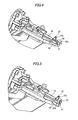
- the contact arm 20 is a wire-rod type contact arm 20 made of a wire rod, as illustrated in FIGs. 4 to 6 .
- the wire-rod is folded back at its leading end portion 20a, and the leading end portion 20a is bent at a substantially right angle in a direction opposite to the grip portion 12a.
- the contact arm 20 is pressed against the work-piece, as illustrated in FIGs. 3 and 5 , the contact arm 20 is pushed in a direction opposite to the driving direction of the fastener, and thus is slid, so that the leading end portion of the nose portion 16 comes in the inside of the U-typed leading end portion 20a of the contact arm 20.
- the leading end portion of the nose portion 16, in which the U-typed leading end portion 20a of the contact arm 20 comes, is provided with a receiving portion by which a load applied to the contact arm 20 is received.
- a build-up portion 23 and a projection 22 are provided as the load receiving portion.
- the build-up portion 23 is provided to be opposed to the inside of the U-typed leading end portion 20a of the contact arm 20 when the contact arm 20 is pushed and slid. To reduce a gap between the inner peripheral side of the U-typed leading end portion 20a and the build-up portion 23, the build-up portion 23 is formed to have a U-type cross section perpendicular to the driving direction so as to correspond to a shape of an inner side of a U-typed part of the U-typed leading end portion 20a. As the build-up portion 23 is provided, the gap between the inner peripheral side of the U-typed leading end portion 20a and the build-up portion 23 is set to be small. In this embodiment, the clearance between the U-typed leading end portion 20a of the contact arm 20 and the build-up portion 23 is set as 1.4 mm or less.
- the projection 22 abuts against the U-typed leading end portion 20a of the contact arm 20, as illustrated in FIGs. 4 to 6 , when the contact arm 20 is pushed and slid.
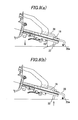
- the projection 22 is provided to protrude more than the contact arm 20 in a direction opposite to the grip portion 12a.
- a height of the projection is set as about 12 mm.
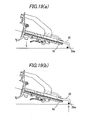
- the height of the projection 22 is set to be higher than a slope of 35 degrees from the leading end portion of the nose portion 16 (see FIG. 8(a) ).
- the driving tool 10 includes the build-up portion 23 and the projection 22. As a result, even in the case where the driving tool 10 is fallen and thus the load is applied to the contact arm 20, it is possible to prevent deformation of the contact arm 20.
- the deformation prevention mechanism according to this embodiment can effectively suppress the deformation of the contact arm 20, as described above.
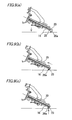
- the contact arm 20 in the case where the contact arm 20 is fallen at a sharp angle and then collides on the concrete surface or the like (see FIG. 9(a) ), the contact arm 20 is pushed and slid by the collision with the concrete surface or the like.
- the build-up portion 23 is formed on the leading end portion of the nose portion 16 in the range of sliding the contact arm 20.
- the build-up portion 23 can receive the load to bend the contact arm 20 in the upward direction, thereby preventing the contact arm 20 from being deformed (see FIG. 9C ).
- the leading end portion of the nose portion 16 is provided with the receiving portion for receiving the load applied to the contact arm 20, even though the contact arm 20 collides on the concrete surface or the like at the time of falling, the load generated by the impact can be absorbed by the receiving portion installed at the leading end portion of the nose portion 16, thereby preventing the deformation of the contact arm 20.
- the build-up portion 23 is provided as the load receiving portion, which is opposed to the inside of the U-typed leading end portion 20a of the contact arm 20 when the contact arm 20 is pushed and slid, the load applied to the contact arm 20 can be absorbed by the build-up portion 23, thereby preventing the deformation of the contact arm 20.
- the projection 22 is provided as the load receiving portion, which abuts against the U-typed leading end portion 20a of the contact arm 20 when the contact arm 20 is pushed and slid, the load applied to the contact arm 20 can be absorbed by the projection 22, thereby preventing the deformation of the contact arm 20.
- the projection 22 is provided to protrude forward further than the contact arm 20 in a position opposite to the grip portion 12a, even in the case where the driving tool 10 is fallen from the side opposite to the grip portion 12a, the projection 22 first comes into contact with the concrete surface or the like earlier than the contact arm 20, thereby preventing the deformation of the contact arm 20.
- only the build-up portion 23 may be provided, without installing the projection 22.
- the deformation of the contact arm 20 is suppressed, without installing the projection 22.
- the projection 22 is omitted, a manufacturing cost thereof can be reduced.
- the nose portion 16 is made compact by eliminating the projection 22, the nose portion 16 can come in a narrow space, and be easily aimed to a driving point.
- the projection 22 is formed to receive the whole leading end portion 20a of the contact arm 20, thereby increasing an area to receive the load of the contact arm 20.
- a plurality of projections 22 may be provided so that the load of the contact arm 20 is received at plural positions.
- the build-up portion 23 may be provided with a groove portion 23a.
- the build-up portion 23 is not limited to the aspect in which it is provided at the whole area of the leading end portion of the nose portion 16 which is opposed to the inside of the U-typed leading end portion 20a of the contact arm 20, but the build-up portion 23 may be formed at a portion of the leading end portion of the nose portion 16.
- U-type means a shape defined by a line extending from one side to the other side and turned back from the other side to the one side at an end of the other side.
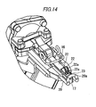
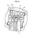
- Examples of the "U-type” may be “U-shape”, “V-shape”, and “C-shape”. That is, the "U-type leading end” may be, for example, a "V-shape leading end”. If the leading end portion 20a of the contact arm 20 has an angular U-shape as shown in FIG. 17 , , the build-up portion 23 may have an angular U-shape cross section, to conform with the shape of the leading end portion 20a of the contact arm 20.
- the contact arm 20 is formed by connecting two leading end portions 20a of wire-type arms which are extended in both sides of the nose portion 16, but the present invention is not limited thereto.
- two wire type arms extended to both sides of the nose portion 16 may be connected to each other in the nose portion 16. That is, the leading end portions 20a may be formed in a substantially U-type and be spaced apart from each other.
- the driving tool 10 operated by the compressed air is given as an example, but the embodiment of the present invention is not limited thereto. It does not matter as long as it is the driving tool 10 including the contact arm 20.
- the present invention can be applied to an electric driving tool or a gas combustion type driving tool.
- a driving tool may include a nose portion 16 that guides a fastener, and a contact arm 20 which is slidable along the nose portion.
- the contact arm 20 may include a U-type leading end portion 20a in which a wire rod is bent into a U-type in a surface intersecting to a driving direction of the fastener.
- the nose portion 16 and the contact arm 20 may be arranged such that a leading end of the nose portion 16 is placed inside of a U-type part of the leading end portion 20a of the contact arm 20 by a sliding of the contact arm 20 toward a base end of the nose portion 16.
- the leading end portion of the nose portion 16 may be provided with a receiving portion 22, 23 by which a load applied to the contact arm is received.
- the leading end portion of the nose portion is provided with the receiving portion for receiving the load applied to the contact arm, even though the contact arm collides on the concrete surface or the like at the time of falling, the load generated by the impact can be absorbed by the receiving portion provided at the leading end portion of the nose portion, thereby preventing the deformation of the contact arm.
- the receiving portion may include a build-up portion 23 formed on the nose portion 16 and having a U-type cross section corresponding to a shape of an inner side of the U-type part of the leading end portion 20a of the contact arm 20.
- the build-up portion is opposed to an inside of the U-type leading end portion of the contact arm when the contact arm is pushed. Therefore, the load applied to the contact arm is absorbed by the build-up portion, thereby preventing the contact arm from being deformed.
- the receiving portion may include a projection 22 to which the leading end portion 20a of the contact arm 20 abuts by the sliding of the contact arm 20 toward the base end of the nose portion 16.
- the receiving portion includes the projection which abuts against the U-type leading end portion of the contact arm when the contact arm is pushed.
- the load applied to the contact arm can be absorbed by the projection, thereby preventing the deformation of the contact arm. That is, even when the sliding movement of the contact arm is finished, the contact arm comes into contact with the projection, and thus the projection directly receives the load, thereby preventing the deformation of the contact arm.
- the driving tool may include a grip 12a extending in a direction perpendicular to the driving direction.
- the projection 22 may protrude further than the contact arm 20 in a direction opposite to said direction that the grip 12a extends.
- the projection protrudes more than the contact arm in the direction opposite to the grip. In this way, even in the case where the driving tool is fallen from the side opposite to the grip portion, the projection first comes into contact with the concrete surface or the like earlier than the contact arm, thereby preventing the deformation of the contact arm.
Landscapes
- Engineering & Computer Science (AREA)
- Mechanical Engineering (AREA)
- Portable Nailing Machines And Staplers (AREA)
- Percussion Or Vibration Massage (AREA)
- Orthopedics, Nursing, And Contraception (AREA)
Applications Claiming Priority (1)
| Application Number | Priority Date | Filing Date | Title |
|---|---|---|---|
| JP2011234855A JP5772506B2 (ja) | 2011-10-26 | 2011-10-26 | コンタクトアームの変形防止機構 |
Publications (3)
| Publication Number | Publication Date |
|---|---|
| EP2586571A2 true EP2586571A2 (de) | 2013-05-01 |
| EP2586571A3 EP2586571A3 (de) | 2015-04-08 |
| EP2586571B1 EP2586571B1 (de) | 2016-08-31 |
Family
ID=47080156
Family Applications (1)
| Application Number | Title | Priority Date | Filing Date |
|---|---|---|---|
| EP12007044.6A Active EP2586571B1 (de) | 2011-10-26 | 2012-10-10 | Setzgerät |
Country Status (5)
| Country | Link |
|---|---|
| US (1) | US9149920B2 (de) |
| EP (1) | EP2586571B1 (de) |
| JP (1) | JP5772506B2 (de) |
| CN (1) | CN103072120B (de) |
| TW (1) | TWI586493B (de) |
Families Citing this family (4)
| Publication number | Priority date | Publication date | Assignee | Title |
|---|---|---|---|---|
| JP5772506B2 (ja) * | 2011-10-26 | 2015-09-02 | マックス株式会社 | コンタクトアームの変形防止機構 |
| TWM568191U (zh) * | 2018-07-16 | 2018-10-11 | 金和利股份有限公司 | Quick release device for nail gun nail gun panel |
| US11141849B2 (en) * | 2018-11-19 | 2021-10-12 | Brahma Industries LLC | Protective shield for use with a staple gun |
| USD1119548S1 (en) * | 2024-01-08 | 2026-03-24 | Techtronic Cordless Gp | Workpiece contact element for a fastener driver |
Citations (3)
| Publication number | Priority date | Publication date | Assignee | Title |
|---|---|---|---|---|
| JPH01286783A (ja) | 1988-05-13 | 1989-11-17 | Matsushita Electric Ind Co Ltd | 超音波モータに用いられるライニング材の加工方法 |
| US20060191973A1 (en) | 2005-02-25 | 2006-08-31 | Basso Industry Corp. | Nail stopper for a skew nailing gun |
| JP2010023174A (ja) | 2008-07-18 | 2010-02-04 | Max Co Ltd | ステープル打ち用釘打機 |
Family Cites Families (20)
| Publication number | Priority date | Publication date | Assignee | Title |
|---|---|---|---|---|
| US3762620A (en) * | 1972-05-15 | 1973-10-02 | Fastener Corp | Safety assembly for fastener driving tool |
| JPS6237659Y2 (de) * | 1981-04-10 | 1987-09-25 | ||
| JPS6328573A (ja) * | 1986-07-18 | 1988-02-06 | 日立工機株式会社 | ガス燃焼式打込機の掃気構造 |
| US5385286A (en) * | 1994-01-07 | 1995-01-31 | Senco Products, Inc. | Adjustable depth control for use with a fastener driving tool |
| WO1996012591A1 (en) * | 1994-10-21 | 1996-05-02 | Senco Products, Inc. | Pneumatic fastener driving tool and an electronic control system therefor |
| US5685473A (en) * | 1996-06-07 | 1997-11-11 | Illinois Tool Works Inc. | Fastener-driving tool having adjustable controlling mechanism |
| JPH10286784A (ja) * | 1997-04-11 | 1998-10-27 | Hitachi Koki Co Ltd | 打込機の打込み深さ調整装置 |
| JPH10286783A (ja) | 1997-04-11 | 1998-10-27 | Hitachi Koki Co Ltd | 打込機のマガジン取付装置 |
| JP3300677B2 (ja) * | 1998-12-10 | 2002-07-08 | 株式会社シンコー | 釘打機 |
| US6722549B2 (en) * | 2002-05-08 | 2004-04-20 | Yury Shkolnikov | Arm member for fastener driving tool |
| US7070079B2 (en) * | 2004-03-05 | 2006-07-04 | Illinois Tool Works Inc. | No-mar tip for fastening tool |
| JP4720656B2 (ja) * | 2006-07-12 | 2011-07-13 | 日立工機株式会社 | 打込機 |
| US7565992B2 (en) * | 2007-05-23 | 2009-07-28 | Illinois Tool Works Inc. | Collapsible protective tip for fastener driver workpiece contact element |
| JP5182549B2 (ja) * | 2007-09-28 | 2013-04-17 | 日立工機株式会社 | 打込機 |
| JP5188873B2 (ja) * | 2008-05-09 | 2013-04-24 | 株式会社マキタ | 携帯工具 |
| JP2010076060A (ja) * | 2008-09-26 | 2010-04-08 | Hitachi Koki Co Ltd | 燃焼式釘打機 |
| US8387846B2 (en) * | 2009-06-08 | 2013-03-05 | Illinois Tool Works Inc | Fastening tool with blind guide work contact tip |
| US8746526B2 (en) * | 2009-09-15 | 2014-06-10 | Robert Bosch Gmbh | Fastener driver with blank fire lockout |
| US8631986B2 (en) * | 2009-12-04 | 2014-01-21 | Robert Bosch Gmbh | Fastener driver with an operating switch |
| JP5772506B2 (ja) * | 2011-10-26 | 2015-09-02 | マックス株式会社 | コンタクトアームの変形防止機構 |
-
2011
- 2011-10-26 JP JP2011234855A patent/JP5772506B2/ja active Active
-
2012
- 2012-10-08 TW TW101137061A patent/TWI586493B/zh active
- 2012-10-10 EP EP12007044.6A patent/EP2586571B1/de active Active
- 2012-10-16 US US13/652,710 patent/US9149920B2/en active Active
- 2012-10-24 CN CN201210410442.4A patent/CN103072120B/zh active Active
Patent Citations (3)
| Publication number | Priority date | Publication date | Assignee | Title |
|---|---|---|---|---|
| JPH01286783A (ja) | 1988-05-13 | 1989-11-17 | Matsushita Electric Ind Co Ltd | 超音波モータに用いられるライニング材の加工方法 |
| US20060191973A1 (en) | 2005-02-25 | 2006-08-31 | Basso Industry Corp. | Nail stopper for a skew nailing gun |
| JP2010023174A (ja) | 2008-07-18 | 2010-02-04 | Max Co Ltd | ステープル打ち用釘打機 |
Also Published As
| Publication number | Publication date |
|---|---|
| JP5772506B2 (ja) | 2015-09-02 |
| CN103072120A (zh) | 2013-05-01 |
| US9149920B2 (en) | 2015-10-06 |
| EP2586571A3 (de) | 2015-04-08 |
| US20130105541A1 (en) | 2013-05-02 |
| TWI586493B (zh) | 2017-06-11 |
| EP2586571B1 (de) | 2016-08-31 |
| JP2013091131A (ja) | 2013-05-16 |
| CN103072120B (zh) | 2016-05-18 |
| TW201334930A (zh) | 2013-09-01 |
Similar Documents
| Publication | Publication Date | Title |
|---|---|---|
| US8622273B2 (en) | Stapler | |
| US9149920B2 (en) | Driving tool including a contact arm | |
| US6953137B2 (en) | Fastener driving tool having contact arm in contact with workpiece | |
| US7721928B2 (en) | Nail-driving device with safety unit | |
| EP3444074B1 (de) | Schraubwerkzeug | |
| CN101743097B (zh) | 用于紧固件驱动工具的致动器销导向装置 | |
| EP2431108B1 (de) | Presswerkzeuganordnung | |
| EP3689550B1 (de) | Angetriebener befestigungsmitteltreiber | |
| US11975433B2 (en) | Driving tool | |
| EP3461244A1 (de) | Gleitschienenanordnung und antriebsmechanismus dafür | |
| US20170274511A1 (en) | Safety device for tackers | |
| US7416100B2 (en) | Setting tool | |
| CN102039580B (zh) | 紧固件打入机 | |
| EP2786841A1 (de) | Schraubendreher für Schraubenbänder und Schraubenzufuhrmechanismus eines Schraubendrehers | |
| KR20060107470A (ko) | 개량형 안전수단이 구비된 타정장치 | |
| US7757921B2 (en) | Driving machine | |
| US9469022B2 (en) | Driving tools | |
| US11077542B2 (en) | Metal connector adaptor for a fastening tool | |
| US12569968B2 (en) | Fastener driving tool with cylindrical driver | |
| EP4506577A1 (de) | Befestigungselementträger, gekoppelter befestigungselement und herstellungsverfahren für befestigungselementträger | |
| JP2008279571A (ja) | 動力駆動釘打機 | |
| TWI404605B (zh) | Used for pinning nail clasps | |
| JP2011104764A (ja) | ファスナー打込み機 | |
| JP5257587B2 (ja) | ステープル打込機 | |
| KR100722208B1 (ko) | 스테플러 |
Legal Events
| Date | Code | Title | Description |
|---|---|---|---|
| PUAI | Public reference made under article 153(3) epc to a published international application that has entered the european phase |
Free format text: ORIGINAL CODE: 0009012 |
|
| 17P | Request for examination filed |
Effective date: 20130226 |
|
| AK | Designated contracting states |
Kind code of ref document: A2 Designated state(s): AL AT BE BG CH CY CZ DE DK EE ES FI FR GB GR HR HU IE IS IT LI LT LU LV MC MK MT NL NO PL PT RO RS SE SI SK SM TR |
|
| AX | Request for extension of the european patent |
Extension state: BA ME |
|
| PUAL | Search report despatched |
Free format text: ORIGINAL CODE: 0009013 |
|
| AK | Designated contracting states |
Kind code of ref document: A3 Designated state(s): AL AT BE BG CH CY CZ DE DK EE ES FI FR GB GR HR HU IE IS IT LI LT LU LV MC MK MT NL NO PL PT RO RS SE SI SK SM TR |
|
| AX | Request for extension of the european patent |
Extension state: BA ME |
|
| RIC1 | Information provided on ipc code assigned before grant |
Ipc: B25C 1/00 20060101AFI20150304BHEP |
|
| RBV | Designated contracting states (corrected) |
Designated state(s): AL AT BE BG CH CY CZ DE DK EE ES FI FR GB GR HR HU IE IS IT LI LT LU LV MC MK MT NL NO PL PT RO RS SE SI SK SM TR |
|
| GRAP | Despatch of communication of intention to grant a patent |
Free format text: ORIGINAL CODE: EPIDOSNIGR1 |
|
| INTG | Intention to grant announced |
Effective date: 20160316 |
|
| GRAS | Grant fee paid |
Free format text: ORIGINAL CODE: EPIDOSNIGR3 |
|
| GRAA | (expected) grant |
Free format text: ORIGINAL CODE: 0009210 |
|
| AK | Designated contracting states |
Kind code of ref document: B1 Designated state(s): AL AT BE BG CH CY CZ DE DK EE ES FI FR GB GR HR HU IE IS IT LI LT LU LV MC MK MT NL NO PL PT RO RS SE SI SK SM TR |
|
| REG | Reference to a national code |
Ref country code: CH Ref legal event code: EP Ref country code: GB Ref legal event code: FG4D |
|
| REG | Reference to a national code |
Ref country code: IE Ref legal event code: FG4D |
|
| REG | Reference to a national code |
Ref country code: DE Ref legal event code: R096 Ref document number: 602012022301 Country of ref document: DE |
|
| REG | Reference to a national code |
Ref country code: AT Ref legal event code: REF Ref document number: 824585 Country of ref document: AT Kind code of ref document: T Effective date: 20161015 |
|
| REG | Reference to a national code |
Ref country code: LT Ref legal event code: MG4D |
|
| REG | Reference to a national code |
Ref country code: NL Ref legal event code: MP Effective date: 20160831 |
|
| REG | Reference to a national code |
Ref country code: AT Ref legal event code: MK05 Ref document number: 824585 Country of ref document: AT Kind code of ref document: T Effective date: 20160831 |
|
| PG25 | Lapsed in a contracting state [announced via postgrant information from national office to epo] |
Ref country code: HR Free format text: LAPSE BECAUSE OF FAILURE TO SUBMIT A TRANSLATION OF THE DESCRIPTION OR TO PAY THE FEE WITHIN THE PRESCRIBED TIME-LIMIT Effective date: 20160831 Ref country code: NO Free format text: LAPSE BECAUSE OF FAILURE TO SUBMIT A TRANSLATION OF THE DESCRIPTION OR TO PAY THE FEE WITHIN THE PRESCRIBED TIME-LIMIT Effective date: 20161130 Ref country code: RS Free format text: LAPSE BECAUSE OF FAILURE TO SUBMIT A TRANSLATION OF THE DESCRIPTION OR TO PAY THE FEE WITHIN THE PRESCRIBED TIME-LIMIT Effective date: 20160831 Ref country code: FI Free format text: LAPSE BECAUSE OF FAILURE TO SUBMIT A TRANSLATION OF THE DESCRIPTION OR TO PAY THE FEE WITHIN THE PRESCRIBED TIME-LIMIT Effective date: 20160831 Ref country code: LT Free format text: LAPSE BECAUSE OF FAILURE TO SUBMIT A TRANSLATION OF THE DESCRIPTION OR TO PAY THE FEE WITHIN THE PRESCRIBED TIME-LIMIT Effective date: 20160831 |
|
| PG25 | Lapsed in a contracting state [announced via postgrant information from national office to epo] |
Ref country code: LV Free format text: LAPSE BECAUSE OF FAILURE TO SUBMIT A TRANSLATION OF THE DESCRIPTION OR TO PAY THE FEE WITHIN THE PRESCRIBED TIME-LIMIT Effective date: 20160831 Ref country code: SE Free format text: LAPSE BECAUSE OF FAILURE TO SUBMIT A TRANSLATION OF THE DESCRIPTION OR TO PAY THE FEE WITHIN THE PRESCRIBED TIME-LIMIT Effective date: 20160831 Ref country code: BE Free format text: LAPSE BECAUSE OF NON-PAYMENT OF DUE FEES Effective date: 20161031 Ref country code: ES Free format text: LAPSE BECAUSE OF FAILURE TO SUBMIT A TRANSLATION OF THE DESCRIPTION OR TO PAY THE FEE WITHIN THE PRESCRIBED TIME-LIMIT Effective date: 20160831 Ref country code: AT Free format text: LAPSE BECAUSE OF FAILURE TO SUBMIT A TRANSLATION OF THE DESCRIPTION OR TO PAY THE FEE WITHIN THE PRESCRIBED TIME-LIMIT Effective date: 20160831 Ref country code: GR Free format text: LAPSE BECAUSE OF FAILURE TO SUBMIT A TRANSLATION OF THE DESCRIPTION OR TO PAY THE FEE WITHIN THE PRESCRIBED TIME-LIMIT Effective date: 20161201 Ref country code: NL Free format text: LAPSE BECAUSE OF FAILURE TO SUBMIT A TRANSLATION OF THE DESCRIPTION OR TO PAY THE FEE WITHIN THE PRESCRIBED TIME-LIMIT Effective date: 20160831 |
|
| PG25 | Lapsed in a contracting state [announced via postgrant information from national office to epo] |
Ref country code: EE Free format text: LAPSE BECAUSE OF FAILURE TO SUBMIT A TRANSLATION OF THE DESCRIPTION OR TO PAY THE FEE WITHIN THE PRESCRIBED TIME-LIMIT Effective date: 20160831 Ref country code: RO Free format text: LAPSE BECAUSE OF FAILURE TO SUBMIT A TRANSLATION OF THE DESCRIPTION OR TO PAY THE FEE WITHIN THE PRESCRIBED TIME-LIMIT Effective date: 20160831 |
|
| PG25 | Lapsed in a contracting state [announced via postgrant information from national office to epo] |
Ref country code: SK Free format text: LAPSE BECAUSE OF FAILURE TO SUBMIT A TRANSLATION OF THE DESCRIPTION OR TO PAY THE FEE WITHIN THE PRESCRIBED TIME-LIMIT Effective date: 20160831 Ref country code: PL Free format text: LAPSE BECAUSE OF FAILURE TO SUBMIT A TRANSLATION OF THE DESCRIPTION OR TO PAY THE FEE WITHIN THE PRESCRIBED TIME-LIMIT Effective date: 20160831 Ref country code: BE Free format text: LAPSE BECAUSE OF FAILURE TO SUBMIT A TRANSLATION OF THE DESCRIPTION OR TO PAY THE FEE WITHIN THE PRESCRIBED TIME-LIMIT Effective date: 20160831 Ref country code: CZ Free format text: LAPSE BECAUSE OF FAILURE TO SUBMIT A TRANSLATION OF THE DESCRIPTION OR TO PAY THE FEE WITHIN THE PRESCRIBED TIME-LIMIT Effective date: 20160831 Ref country code: DK Free format text: LAPSE BECAUSE OF FAILURE TO SUBMIT A TRANSLATION OF THE DESCRIPTION OR TO PAY THE FEE WITHIN THE PRESCRIBED TIME-LIMIT Effective date: 20160831 Ref country code: PT Free format text: LAPSE BECAUSE OF FAILURE TO SUBMIT A TRANSLATION OF THE DESCRIPTION OR TO PAY THE FEE WITHIN THE PRESCRIBED TIME-LIMIT Effective date: 20170102 Ref country code: BG Free format text: LAPSE BECAUSE OF FAILURE TO SUBMIT A TRANSLATION OF THE DESCRIPTION OR TO PAY THE FEE WITHIN THE PRESCRIBED TIME-LIMIT Effective date: 20161130 Ref country code: SM Free format text: LAPSE BECAUSE OF FAILURE TO SUBMIT A TRANSLATION OF THE DESCRIPTION OR TO PAY THE FEE WITHIN THE PRESCRIBED TIME-LIMIT Effective date: 20160831 |
|
| REG | Reference to a national code |
Ref country code: CH Ref legal event code: PL |
|
| REG | Reference to a national code |
Ref country code: DE Ref legal event code: R097 Ref document number: 602012022301 Country of ref document: DE |
|
| PG25 | Lapsed in a contracting state [announced via postgrant information from national office to epo] |
Ref country code: IT Free format text: LAPSE BECAUSE OF FAILURE TO SUBMIT A TRANSLATION OF THE DESCRIPTION OR TO PAY THE FEE WITHIN THE PRESCRIBED TIME-LIMIT Effective date: 20160831 |
|
| PLBE | No opposition filed within time limit |
Free format text: ORIGINAL CODE: 0009261 |
|
| STAA | Information on the status of an ep patent application or granted ep patent |
Free format text: STATUS: NO OPPOSITION FILED WITHIN TIME LIMIT |
|
| GBPC | Gb: european patent ceased through non-payment of renewal fee |
Effective date: 20161130 |
|
| REG | Reference to a national code |
Ref country code: IE Ref legal event code: MM4A |
|
| REG | Reference to a national code |
Ref country code: FR Ref legal event code: ST Effective date: 20170630 |
|
| PG25 | Lapsed in a contracting state [announced via postgrant information from national office to epo] |
Ref country code: CH Free format text: LAPSE BECAUSE OF NON-PAYMENT OF DUE FEES Effective date: 20161031 Ref country code: LI Free format text: LAPSE BECAUSE OF NON-PAYMENT OF DUE FEES Effective date: 20161031 Ref country code: FR Free format text: LAPSE BECAUSE OF NON-PAYMENT OF DUE FEES Effective date: 20161102 |
|
| 26N | No opposition filed |
Effective date: 20170601 |
|
| PG25 | Lapsed in a contracting state [announced via postgrant information from national office to epo] |
Ref country code: SI Free format text: LAPSE BECAUSE OF FAILURE TO SUBMIT A TRANSLATION OF THE DESCRIPTION OR TO PAY THE FEE WITHIN THE PRESCRIBED TIME-LIMIT Effective date: 20160831 Ref country code: LU Free format text: LAPSE BECAUSE OF NON-PAYMENT OF DUE FEES Effective date: 20161010 |
|
| PG25 | Lapsed in a contracting state [announced via postgrant information from national office to epo] |
Ref country code: GB Free format text: LAPSE BECAUSE OF NON-PAYMENT OF DUE FEES Effective date: 20161130 Ref country code: IE Free format text: LAPSE BECAUSE OF NON-PAYMENT OF DUE FEES Effective date: 20161010 |
|
| PG25 | Lapsed in a contracting state [announced via postgrant information from national office to epo] |
Ref country code: CY Free format text: LAPSE BECAUSE OF FAILURE TO SUBMIT A TRANSLATION OF THE DESCRIPTION OR TO PAY THE FEE WITHIN THE PRESCRIBED TIME-LIMIT Effective date: 20160831 Ref country code: HU Free format text: LAPSE BECAUSE OF FAILURE TO SUBMIT A TRANSLATION OF THE DESCRIPTION OR TO PAY THE FEE WITHIN THE PRESCRIBED TIME-LIMIT; INVALID AB INITIO Effective date: 20121010 |
|
| PG25 | Lapsed in a contracting state [announced via postgrant information from national office to epo] |
Ref country code: MT Free format text: LAPSE BECAUSE OF NON-PAYMENT OF DUE FEES Effective date: 20161031 Ref country code: MC Free format text: LAPSE BECAUSE OF FAILURE TO SUBMIT A TRANSLATION OF THE DESCRIPTION OR TO PAY THE FEE WITHIN THE PRESCRIBED TIME-LIMIT Effective date: 20160831 Ref country code: IS Free format text: LAPSE BECAUSE OF FAILURE TO SUBMIT A TRANSLATION OF THE DESCRIPTION OR TO PAY THE FEE WITHIN THE PRESCRIBED TIME-LIMIT Effective date: 20160831 Ref country code: MK Free format text: LAPSE BECAUSE OF FAILURE TO SUBMIT A TRANSLATION OF THE DESCRIPTION OR TO PAY THE FEE WITHIN THE PRESCRIBED TIME-LIMIT Effective date: 20160831 Ref country code: TR Free format text: LAPSE BECAUSE OF FAILURE TO SUBMIT A TRANSLATION OF THE DESCRIPTION OR TO PAY THE FEE WITHIN THE PRESCRIBED TIME-LIMIT Effective date: 20160831 |
|
| PG25 | Lapsed in a contracting state [announced via postgrant information from national office to epo] |
Ref country code: AL Free format text: LAPSE BECAUSE OF FAILURE TO SUBMIT A TRANSLATION OF THE DESCRIPTION OR TO PAY THE FEE WITHIN THE PRESCRIBED TIME-LIMIT Effective date: 20160831 |
|
| PGFP | Annual fee paid to national office [announced via postgrant information from national office to epo] |
Ref country code: DE Payment date: 20250902 Year of fee payment: 14 |