EP2586105B1 - Connecteur enfichable - Google Patents
Connecteur enfichable Download PDFInfo
- Publication number
- EP2586105B1 EP2586105B1 EP11729901.6A EP11729901A EP2586105B1 EP 2586105 B1 EP2586105 B1 EP 2586105B1 EP 11729901 A EP11729901 A EP 11729901A EP 2586105 B1 EP2586105 B1 EP 2586105B1
- Authority
- EP
- European Patent Office
- Prior art keywords
- outer conductor
- conductor part
- ring
- plug
- housing
- Prior art date
- Legal status (The legal status is an assumption and is not a legal conclusion. Google has not performed a legal analysis and makes no representation as to the accuracy of the status listed.)
- Active
Links
- 239000004020 conductor Substances 0.000 claims description 82
- 239000012858 resilient material Substances 0.000 claims description 3
- 230000000295 complement effect Effects 0.000 description 4
- 239000012212 insulator Substances 0.000 description 4
- 230000013011 mating Effects 0.000 description 3
- 239000002184 metal Substances 0.000 description 3
- 239000003989 dielectric material Substances 0.000 description 2
- 238000009434 installation Methods 0.000 description 1
- 230000003993 interaction Effects 0.000 description 1
- 239000000463 material Substances 0.000 description 1
- 230000000630 rising effect Effects 0.000 description 1
- 238000005476 soldering Methods 0.000 description 1
- 230000008719 thickening Effects 0.000 description 1
Images

Classifications
-
- H—ELECTRICITY
- H01—ELECTRIC ELEMENTS
- H01R—ELECTRICALLY-CONDUCTIVE CONNECTIONS; STRUCTURAL ASSOCIATIONS OF A PLURALITY OF MUTUALLY-INSULATED ELECTRICAL CONNECTING ELEMENTS; COUPLING DEVICES; CURRENT COLLECTORS
- H01R13/00—Details of coupling devices of the kinds covered by groups H01R12/70 or H01R24/00 - H01R33/00
- H01R13/648—Protective earth or shield arrangements on coupling devices, e.g. anti-static shielding
- H01R13/6485—Electrostatic discharge protection
-
- H—ELECTRICITY
- H01—ELECTRIC ELEMENTS
- H01R—ELECTRICALLY-CONDUCTIVE CONNECTIONS; STRUCTURAL ASSOCIATIONS OF A PLURALITY OF MUTUALLY-INSULATED ELECTRICAL CONNECTING ELEMENTS; COUPLING DEVICES; CURRENT COLLECTORS
- H01R13/00—Details of coupling devices of the kinds covered by groups H01R12/70 or H01R24/00 - H01R33/00
- H01R13/62—Means for facilitating engagement or disengagement of coupling parts or for holding them in engagement
-
- H—ELECTRICITY
- H01—ELECTRIC ELEMENTS
- H01R—ELECTRICALLY-CONDUCTIVE CONNECTIONS; STRUCTURAL ASSOCIATIONS OF A PLURALITY OF MUTUALLY-INSULATED ELECTRICAL CONNECTING ELEMENTS; COUPLING DEVICES; CURRENT COLLECTORS
- H01R9/00—Structural associations of a plurality of mutually-insulated electrical connecting elements, e.g. terminal strips or terminal blocks; Terminals or binding posts mounted upon a base or in a case; Bases therefor
- H01R9/03—Connectors arranged to contact a plurality of the conductors of a multiconductor cable, e.g. tapping connections
- H01R9/05—Connectors arranged to contact a plurality of the conductors of a multiconductor cable, e.g. tapping connections for coaxial cables
-
- H—ELECTRICITY
- H01—ELECTRIC ELEMENTS
- H01R—ELECTRICALLY-CONDUCTIVE CONNECTIONS; STRUCTURAL ASSOCIATIONS OF A PLURALITY OF MUTUALLY-INSULATED ELECTRICAL CONNECTING ELEMENTS; COUPLING DEVICES; CURRENT COLLECTORS
- H01R13/00—Details of coupling devices of the kinds covered by groups H01R12/70 or H01R24/00 - H01R33/00
- H01R13/02—Contact members
- H01R13/15—Pins, blades or sockets having separate spring member for producing or increasing contact pressure
- H01R13/18—Pins, blades or sockets having separate spring member for producing or increasing contact pressure with the spring member surrounding the socket
-
- H—ELECTRICITY
- H01—ELECTRIC ELEMENTS
- H01R—ELECTRICALLY-CONDUCTIVE CONNECTIONS; STRUCTURAL ASSOCIATIONS OF A PLURALITY OF MUTUALLY-INSULATED ELECTRICAL CONNECTING ELEMENTS; COUPLING DEVICES; CURRENT COLLECTORS
- H01R13/00—Details of coupling devices of the kinds covered by groups H01R12/70 or H01R24/00 - H01R33/00
- H01R13/46—Bases; Cases
- H01R13/502—Bases; Cases composed of different pieces
-
- H—ELECTRICITY
- H01—ELECTRIC ELEMENTS
- H01R—ELECTRICALLY-CONDUCTIVE CONNECTIONS; STRUCTURAL ASSOCIATIONS OF A PLURALITY OF MUTUALLY-INSULATED ELECTRICAL CONNECTING ELEMENTS; COUPLING DEVICES; CURRENT COLLECTORS
- H01R13/00—Details of coupling devices of the kinds covered by groups H01R12/70 or H01R24/00 - H01R33/00
- H01R13/64—Means for preventing incorrect coupling
-
- H—ELECTRICITY
- H01—ELECTRIC ELEMENTS
- H01R—ELECTRICALLY-CONDUCTIVE CONNECTIONS; STRUCTURAL ASSOCIATIONS OF A PLURALITY OF MUTUALLY-INSULATED ELECTRICAL CONNECTING ELEMENTS; COUPLING DEVICES; CURRENT COLLECTORS
- H01R13/00—Details of coupling devices of the kinds covered by groups H01R12/70 or H01R24/00 - H01R33/00
- H01R13/648—Protective earth or shield arrangements on coupling devices, e.g. anti-static shielding
- H01R13/652—Protective earth or shield arrangements on coupling devices, e.g. anti-static shielding with earth pin, blade or socket
-
- H—ELECTRICITY
- H01—ELECTRIC ELEMENTS
- H01R—ELECTRICALLY-CONDUCTIVE CONNECTIONS; STRUCTURAL ASSOCIATIONS OF A PLURALITY OF MUTUALLY-INSULATED ELECTRICAL CONNECTING ELEMENTS; COUPLING DEVICES; CURRENT COLLECTORS
- H01R13/00—Details of coupling devices of the kinds covered by groups H01R12/70 or H01R24/00 - H01R33/00
- H01R13/648—Protective earth or shield arrangements on coupling devices, e.g. anti-static shielding
- H01R13/655—Protective earth or shield arrangements on coupling devices, e.g. anti-static shielding with earth brace
-
- H—ELECTRICITY
- H01—ELECTRIC ELEMENTS
- H01R—ELECTRICALLY-CONDUCTIVE CONNECTIONS; STRUCTURAL ASSOCIATIONS OF A PLURALITY OF MUTUALLY-INSULATED ELECTRICAL CONNECTING ELEMENTS; COUPLING DEVICES; CURRENT COLLECTORS
- H01R13/00—Details of coupling devices of the kinds covered by groups H01R12/70 or H01R24/00 - H01R33/00
- H01R13/648—Protective earth or shield arrangements on coupling devices, e.g. anti-static shielding
- H01R13/658—High frequency shielding arrangements, e.g. against EMI [Electro-Magnetic Interference] or EMP [Electro-Magnetic Pulse]
- H01R13/6581—Shield structure
- H01R13/6582—Shield structure with resilient means for engaging mating connector
- H01R13/6583—Shield structure with resilient means for engaging mating connector with separate conductive resilient members between mating shield members
-
- H—ELECTRICITY
- H01—ELECTRIC ELEMENTS
- H01R—ELECTRICALLY-CONDUCTIVE CONNECTIONS; STRUCTURAL ASSOCIATIONS OF A PLURALITY OF MUTUALLY-INSULATED ELECTRICAL CONNECTING ELEMENTS; COUPLING DEVICES; CURRENT COLLECTORS
- H01R13/00—Details of coupling devices of the kinds covered by groups H01R12/70 or H01R24/00 - H01R33/00
- H01R13/648—Protective earth or shield arrangements on coupling devices, e.g. anti-static shielding
- H01R13/658—High frequency shielding arrangements, e.g. against EMI [Electro-Magnetic Interference] or EMP [Electro-Magnetic Pulse]
- H01R13/6581—Shield structure
- H01R13/659—Shield structure with plural ports for distinct connectors
Definitions
- the present invention relates to a connector having an outer conductor part, which is designed for electrical and mechanical connection to an outer conductor of a cable and forms an electromagnetic shield of the connector, with an insulating part, which is designed to hold at least one inner conductor part at a predetermined position relative to the outer conductor part , according to the preamble of claim 1.
- the connector has an outer conductor part, an insulating part and an electrical contact.
- the outer conductor part is designed for electrical and mechanical connection to a coaxial cable and has ribs on its inner surface.
- An inner diameter of the outer conductor part is slightly larger than an outer diameter of the insulating part and four ribs rise radially inward from the inner surface of the outer conductor part. These four ribs form a press fit for the inner conductor part, so that rotation of the insulating part is prevented relative to the outer conductor part.
- a BNC Winket connector which has a housing for soldering onto a circuit board, in which an outer conductor part is arranged, known.
- an outer conductor part In the outer conductor part an insulating part is arranged, which holds an inner conductor.
- the outer conductor part has a circumferential groove formed at one end of the reduced diameter outer conductor part. Within this circumferential groove diametrically opposite elevations are formed.
- a C-shaped spring metal band with a pair of recesses is inserted into the circumferential groove so that the groove blocks axial movement of the spring metal band.
- the recesses of the Federmetallbandes take on the elevations of the outer conductor part to fix the Federmetallband in the circumferential groove and to provide an anti-rotation function within the circumferential groove.
- a rotation for the spring metal band is realized relative to the outer conductor part.
- an anti-rotation device for the outer conductor part is realized relative to the housing via an interaction of a flat surface on the outer conductor part and a corresponding flat surface within the housing.
- an electrical connector with an outer conductor part, an insulating part, which is arranged in an axial bore of the outer conductor part, and an inner conductor, which is arranged in an axial bore of the insulating part known. Furthermore, an anti-rotation device for the inner conductor relative to the insulating part and an anti-rotation for the insulating part is provided relative to the outer conductor part. On the inside of the outer conductor part elevations are arranged, which dig when inserting the insulating part in the softer material of the insulating part. There is no housing provided in which the outer conductor part and the insulating part would be arranged.
- the connector for a coaxial cable having an inner conductor, an outer conductor and a dielectric disposed therebetween known.
- the connector has a rear threaded nut Internal thread, which receives a rear end of an externally threaded.
- the connector housing has a recess for receiving an electrically conductive, compressible ring.
- the ring presses the outer conductor of the coaxial cable against a ramped wall portion of the threaded nut when the connector housing and the threaded nut are bolted together. This pressure function of the ring ensures an electrically conductive connection between the outer conductor of the coaxial cable and the ramp-shaped wall section by providing a constant contact force.
- the ring provides an anti-twist device for the coaxial cable relative to the connector housing and the threaded nut. An anti-rotation device for the insulating part of the connector is not provided.
- the invention has for its object to provide a connector of o.g. To improve type of assembly and functional safety.
- a housing in which the outer conductor part and the insulating part are arranged, wherein a rotation is provided, which is rotatably connected to the housing and engages through the outer conductor part into the insulating part such that the insulating part and the housing is rotatably connected to each other via the rotation
- a particularly reliable and easy to install anti-rotation is achieved in that the rotation is formed as a ring, in particular C-ring, which engages around the outer conductor part on its outer circumference and has a radially inwardly uplifting pin which passes through the outer conductor part in the Insulating part engages.
- a particularly reliable mechanical connection between the ring and the outer conductor part is achieved in that the pin engages through an opening in the outer side part, which is designed such that a rotational movement of the ring is blocked relative to the outer conductor part.
- a particularly reliable mechanical connection between the ring and the inner conductor part is achieved in that the pin engages in a recess in the insulating part, which is designed such that a rotational movement of the insulating part is blocked relative to the ring.
- a simple assembly and disassembly of the rotation on the housing obtained by the fact that the ring is formed of a resilient material.
- An additional axial securing of the ring relative to the housing is achieved in that on the outer circumference of the outer conductor part, a radially encircling groove is formed, in which the ring is arranged.
- An automatic installation of the anti-rotation with the mounting of the housing is achieved in that the anti-rotation is formed integrally with the housing.
- a connector for a cable with one or more inner conductors is achieved in a simple manner by providing at least one inner conductor part, which is designed for electrical and mechanical connection to an inner conductor of a cable, in particular an HF cable or a power cable.
- a connector in the Fig. 1 illustrated, preferred embodiment of a connector according to the invention comprises a housing 10, a radially disposed within the housing 10 outer conductor part 12 and a radially disposed within the outer conductor part insulating member 14.
- the housing 10, the outer conductor part 12 and the insulating member 14 are arranged coaxially to each other.
- the connector has a male end 16 for mating with a complementary connector (not shown), and a cable end 18 for electrically and mechanically connecting to a cable (not shown) having an outer conductor as the electromagnetic shield and at least one inner conductor.
- the outer conductor part 12 is designed for electrical and mechanical connection to the outer conductor (not shown) of the cable.
- the insulating part 14 is configured to receive at least one inner conductor part (not shown) such that the insulating part 14 holds the inner conductor part (s) at a predetermined position within the outer conductor part 12 and isolates it electrically with respect to the outer conductor part 12.
- the insulating part 14 is for example made of a made of dielectric material, wherein geometric dimensions and dielectric material are selected such that there is a predetermined impedance of the connector.
- the connector according to the invention can also be used for transmitting RF signals.
- an anti-rotation device 20 is arranged in the form of a C-ring, said C-ring 20 is aligned substantially parallel to a plane perpendicular to a longitudinal axis of the housing 10.
- the rotation lock 20 forms a circle segment or is a ring which is interrupted at one point.
- the rotation lock 20 is formed for example of a resilient material, so that the C-ring 20 can be bent radially inwardly or outwardly and then automatically returns under the action of a resilient force in its initial position. This allows mounting of the C-ring 20 on the outside of the outer conductor part 12 after its completion.
- the C-ring 20 for example, radially expanded and guided in the axial direction over the outer conductor part 12 until a predetermined point on the outer circumference of the outer conductor part 12 is reached, on which, for example, a groove 22 for receiving the C-ring 20 is formed. At this point, the C-ring 20 is relieved again, so that it comes to rest in its initial position in the groove 22 on the outer circumference of the outer conductor part 12.
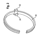
- the anti-rotation device 20 is used for rotationally fixed fixing of the insulating part 14 within the housing 10 by means of a radially inwardly of the anti-rotation 20 rising pin 24, as described below with reference to Fig. 2 will be explained in more detail.
- Fig. 2 illustrates an anti-rotation 20 in the form of the C-ring with the pin 24.
- the C-ring 20 has a cuboidal thickening 32, which engages in a corresponding recess in an inner circumference of the housing 10. In this way, the C-ring 20 is rotatably connected to the housing 10 mechanically. How out Fig.
- the recess in the inner circumference of the housing 10 is formed as extending in the axial direction of groove 30 whose width is selected in the circumferential direction such that the cuboidal design of the C-ring 20 fits into it, however, a rotational movement of the C-ring 20 relative to the housing 10 by striking the cuboidal design of the C-ring 20 on inner walls of the groove 30 is prevented.
- the pin 24 engages through a through hole 26 in the outer conductor part 12 and into a groove 28 in the insulating member 14 so that the C-ring 20 is also rotatably connected to the insulating member 14.
- the insulating member 14 is rotatably connected to the housing 10, wherein the outer conductor part 12 has no function for this rotationally fixed connection between the housing 10 and insulating part 14.
- the outer conductor part 12 is no longer part of the tolerance chain for the rotation of the insulating part 14 in the housing 10th
- the rotation lock 20 ensures a predetermined orientation of the inner conductor parts held in the insulating part 14 relative to the housing 10. This ensures that when inserting the connector according to the invention in a complementary connector, the respective inner conductor portion of the connector according to the invention with a respective desired inner conductor portion of the complementary connector comes into electrical and mechanical contact.
- the arrangement of the inner conductor parts in the connector according to the invention corresponds to the arrangement of the inner conductor parts in the complementary connector.
Claims (8)
- Connecteur enfichable comprenant une partie conductrice extérieure (12), qui est réalisée pour la connexion électrique et mécanique avec un conducteur extérieur d'un câble et qui forme un blindage électromagnétique du connecteur enfichable, comprenant une partie isolante (14), qui est réalisée pour maintenir au moins une partie conductrice intérieure à une position prédéterminée par rapport à la partie conductrice extérieure (12),
caractérisé en ce que
il est prévu un boîtier (10) dans lequel sont agencées la partie conductrice extérieure (12) et la partie isolante (14), dans lequel est prévu un blocage antirotation (20), qui est relié solidairement en rotation avec le boîtier (10) et qui s'engage, en traversant la partie conductrice extérieure (12), jusque dans la partie isolante (14) de telle façon que la partie isolante (14) et le boîtier (10) sont reliés solidairement en rotation l'une avec l'autre via le blocage antirotation (20). - Connecteur enfichable selon la revendication 1, caractérisé en ce que le blocage antirotation (20) est réalisé sous la forme d'un anneau, en particulier un anneau en C, qui enserre la partie conductrice extérieure (12) à sa périphérie extérieure et qui comporte un téton (24) en saillie radialement vers l'intérieur, qui s'engage, en traversant la partie conductrice extérieure (12), jusque dans la partie isolante (14).
- Connecteur enfichable selon la revendication 2, caractérisé en ce que le téton (24) s'engage à travers une traversée (24) dans la partie conductrice extérieure (12), traversée qui est réalisée de telle façon qu'un mouvement de rotation de l'anneau (20) par rapport à la partie conductrice extérieure (12) est bloqué.
- Connecteur enfichable selon la revendication 2 ou 3, caractérisé en ce que le téton (24) s'engage dans un évidement (28) dans la partie isolante (14), évidement qui est réalisé de telle façon qu'un mouvement de rotation de la partie isolante (14) par rapport à l'anneau (20) est bloqué.
- Connecteur enfichable selon l'une au moins des revendications 2 à 4, caractérisé en ce que l'anneau (20) est réalisé en un matériau présentant l'élasticité d'un ressort.
- Connecteur enfichable selon l'une au moins des revendications 2 à 5, caractérisé en ce qu'une gorge radiale périphérique (22) est réalisée à la périphérie extérieure de la partie conductrice extérieure (12), gorge dans laquelle est agencé l'anneau (20).
- Connecteur enfichable selon l'une au moins des revendications précédentes, caractérisé en ce que le blocage antirotation (20) est réalisé d'une seule pièce avec le boîtier (10).
- Connecteur enfichable selon l'une au moins des revendications précédentes, caractérisé en ce qu'il est prévu au moins une partie conductrice intérieure, qui est réalisée pour la connexion électrique et mécanique avec un conducteur intérieur d'un câble, en particulier un câble HF ou un câble d'alimentation électrique.
Applications Claiming Priority (2)
| Application Number | Priority Date | Filing Date | Title |
|---|---|---|---|
| DE202010009599U DE202010009599U1 (de) | 2010-06-28 | 2010-06-28 | Steckverbinder |
| PCT/EP2011/002728 WO2012000596A1 (fr) | 2010-06-28 | 2011-06-01 | Connecteur enfichable |
Publications (2)
| Publication Number | Publication Date |
|---|---|
| EP2586105A1 EP2586105A1 (fr) | 2013-05-01 |
| EP2586105B1 true EP2586105B1 (fr) | 2014-04-02 |
Family
ID=42751413
Family Applications (1)
| Application Number | Title | Priority Date | Filing Date |
|---|---|---|---|
| EP11729901.6A Active EP2586105B1 (fr) | 2010-06-28 | 2011-06-01 | Connecteur enfichable |
Country Status (11)
| Country | Link |
|---|---|
| US (1) | US8905787B2 (fr) |
| EP (1) | EP2586105B1 (fr) |
| JP (1) | JP2013539154A (fr) |
| KR (1) | KR101767117B1 (fr) |
| CN (1) | CN102959809B (fr) |
| CA (1) | CA2800754C (fr) |
| DE (1) | DE202010009599U1 (fr) |
| HK (1) | HK1182534A1 (fr) |
| TW (1) | TWM418456U (fr) |
| WO (1) | WO2012000596A1 (fr) |
| ZA (1) | ZA201208980B (fr) |
Families Citing this family (4)
| Publication number | Priority date | Publication date | Assignee | Title |
|---|---|---|---|---|
| CN103594863B (zh) * | 2013-10-22 | 2015-11-18 | 资阳晨风电气有限公司 | 一种止退器 |
| CN104882751A (zh) * | 2015-06-02 | 2015-09-02 | 杨晓锋 | 高稳定性射频同轴连接器 |
| EP3767750B1 (fr) * | 2019-07-16 | 2022-03-02 | Rosenberger Hochfrequenztechnik GmbH & Co. KG | Connecteur enfichable électrique, élément de protection isolant et procédé de montage d'un connecteur enfichable électrique |
| CN112909660B (zh) * | 2021-01-20 | 2022-04-22 | 中航光电科技股份有限公司 | 一种连接器组件 |
Family Cites Families (49)
| Publication number | Priority date | Publication date | Assignee | Title |
|---|---|---|---|---|
| US5011426A (en) | 1990-02-02 | 1991-04-30 | Molex Incorporated | Electrical connector assembly for vehicular suspension system component |
| US5145412A (en) | 1991-10-18 | 1992-09-08 | Foxconn International, Inc. | Filter connector |
| US5453025A (en) | 1994-02-24 | 1995-09-26 | Redev Management Corp. | Electrical connector |
| US5489222A (en) | 1994-09-09 | 1996-02-06 | The Whitaker Corporation | Mini connector with anti-rotational contact |
| JP3266750B2 (ja) * | 1994-09-16 | 2002-03-18 | 矢崎総業株式会社 | シールドコネクタの絶縁構造 |
| JP3032939B2 (ja) * | 1994-11-29 | 2000-04-17 | 矢崎総業株式会社 | シールドコネクタ |
| JP3585061B2 (ja) * | 1995-06-06 | 2004-11-04 | 矢崎総業株式会社 | シールドコネクタ |
| JP2978953B2 (ja) * | 1995-12-29 | 1999-11-15 | モレックス インコーポレーテッド | プラグ型電気コネクタとその製造方法 |
| US5928032A (en) * | 1997-01-31 | 1999-07-27 | Lucent Technologies, Inc. | Coaxial cable power adapter |
| JP3446989B2 (ja) * | 1997-05-29 | 2003-09-16 | 矢崎総業株式会社 | シールドコネクタ |
| JP3534290B2 (ja) * | 1997-08-07 | 2004-06-07 | 矢崎総業株式会社 | シールドコネクタ |
| JPH11102752A (ja) * | 1997-09-29 | 1999-04-13 | Yazaki Corp | シールドコネクタ |
| US5938465A (en) * | 1997-10-15 | 1999-08-17 | Palco Connector, Inc. | Machined dual spring ring connector for coaxial cable |
| JP3797585B2 (ja) * | 1998-08-11 | 2006-07-19 | 矢崎総業株式会社 | シールドコネクタ |
| FR2803696B1 (fr) * | 2000-01-06 | 2004-01-02 | Radiall Sa | Element de connecteur electrique coaxial realisant egalement une fonction de commutation |
| JP3604314B2 (ja) * | 2000-02-03 | 2004-12-22 | 松下電器産業株式会社 | Xsrケーブルコネクタ |
| JP2002042989A (ja) * | 2000-07-21 | 2002-02-08 | Sumitomo Wiring Syst Ltd | シールド端子 |
| FR2825195B1 (fr) * | 2001-05-22 | 2003-12-12 | Radiall Sa | Dispositif de connexion electrique coaxial coude |
| EP1263089B1 (fr) * | 2001-05-29 | 2003-05-21 | Gerhard Petri GmbH & Co. KG | Arrangement de connexion pour câbles |
| TW540890U (en) * | 2001-08-24 | 2003-07-01 | Hon Hai Prec Ind Co Ltd | Cable connector assembly |
| US6929482B2 (en) * | 2003-01-27 | 2005-08-16 | Litton Systems, Inc. | Interconnection arrangement |
| JP2004327075A (ja) * | 2003-04-21 | 2004-11-18 | Sumitomo Wiring Syst Ltd | コネクタ |
| FR2857510B1 (fr) * | 2003-07-10 | 2005-10-07 | Arnould App Electr | Dispositif de connexion pour cable coaxial |
| JP2005108510A (ja) * | 2003-09-29 | 2005-04-21 | Clarion Co Ltd | 多極型高周波同軸コネクタ |
| US6932645B2 (en) * | 2003-12-31 | 2005-08-23 | Capativa Tech, Inc. | Structure of signal plug |
| US7198507B2 (en) * | 2005-02-09 | 2007-04-03 | Times Microwave Systems, Inc., division of Smiths Aerospace, Incorporated | Handgrip device for coaxial cable and coaxial cable assembly including handgrip device |
| TWM284120U (en) * | 2005-05-18 | 2005-12-21 | Time Technology Ind Co Ltd F | Improved structure of a coaxial connector |
| CN100550536C (zh) * | 2005-06-09 | 2009-10-14 | 株式会社自动网络技术研究所 | 同轴连接器和同轴连接器的连接器外壳的安装结构 |
| JP4753887B2 (ja) * | 2006-04-07 | 2011-08-24 | 株式会社オーディオテクニカ | マイクロホンのコネクタおよびそのシールド方法 |
| FR2901066A1 (fr) * | 2006-05-15 | 2007-11-16 | Radiall Sa | Connecteur coaxial |
| JP4965226B2 (ja) * | 2006-06-23 | 2012-07-04 | 株式会社オートネットワーク技術研究所 | 外導体端子 |
| DE202006011850U1 (de) * | 2006-08-02 | 2006-10-05 | Harting Electric Gmbh & Co. Kg | Kontaktelement für geschirmte Steckverbinder |
| JP4797892B2 (ja) * | 2006-09-07 | 2011-10-19 | 住友電装株式会社 | シールドコネクタ |
| CN101212108A (zh) | 2006-12-29 | 2008-07-02 | 鸿富锦精密工业(深圳)有限公司 | 线缆连接器插头 |
| TWM327118U (en) * | 2007-05-22 | 2008-02-11 | Insert Entpr Co Ltd | Super-miniature coaxial micro switch connector |
| JP4445982B2 (ja) * | 2007-06-29 | 2010-04-07 | ホシデン株式会社 | コネクタ |
| KR100901409B1 (ko) * | 2007-07-06 | 2009-06-05 | 현대자동차주식회사 | 동축 케이블 커넥터 |
| US7425153B1 (en) * | 2007-09-25 | 2008-09-16 | D'addario & Company, Inc. | Electronic connector |
| ATE490577T1 (de) * | 2007-10-04 | 2010-12-15 | 3M Innovative Properties Co | Eine auf dem gebiet der telekommunikation an einen verbinder anfügbare abschirmung, eine kombination des verbinders und mindestens einer abschirmung und verfahren zum abschirmen eines verbinders |
| JP5186170B2 (ja) * | 2007-10-05 | 2013-04-17 | 矢崎総業株式会社 | 導電部材、その導電部材を有するコネクタ |
| US7503776B1 (en) * | 2007-12-07 | 2009-03-17 | Lear Corporation | Grounding connector for a shielded cable |
| US7695333B2 (en) * | 2007-12-13 | 2010-04-13 | Cooper Technologies Company | Single pole cable connector |
| US7645162B2 (en) * | 2008-01-24 | 2010-01-12 | Tyco Electronics Corporation | Connector assembly having a slider element |
| US7708591B2 (en) * | 2008-05-22 | 2010-05-04 | Yazaki Corporation | Shield connector |
| US7635283B1 (en) * | 2008-11-24 | 2009-12-22 | Andrew Llc | Connector with retaining ring for coaxial cable and associated methods |
| US7909646B2 (en) * | 2009-08-10 | 2011-03-22 | 3M Innovative Properties Company | Electrical carrier assembly and system of electrical carrier assemblies |
| DE202010009597U1 (de) * | 2010-06-28 | 2010-09-09 | Rosenberger Hochfrequenztechnik Gmbh & Co. Kg | Steckverbinder mit einer radial wirkenden Rasteinrichtung |
| TWI463756B (zh) * | 2011-04-05 | 2014-12-01 | Belden Inc | 固鎖及密封連接器 |
| US8466378B1 (en) * | 2011-07-05 | 2013-06-18 | Arlington Industries, Inc. | Snap-in electrical cable connector with raised grounding lug |
-
2010
- 2010-06-28 DE DE202010009599U patent/DE202010009599U1/de not_active Expired - Lifetime
-
2011
- 2011-06-01 EP EP11729901.6A patent/EP2586105B1/fr active Active
- 2011-06-01 KR KR1020127032445A patent/KR101767117B1/ko active IP Right Grant
- 2011-06-01 JP JP2013517052A patent/JP2013539154A/ja not_active Withdrawn
- 2011-06-01 WO PCT/EP2011/002728 patent/WO2012000596A1/fr active Application Filing
- 2011-06-01 CN CN201180032106.4A patent/CN102959809B/zh active Active
- 2011-06-01 CA CA2800754A patent/CA2800754C/fr not_active Expired - Fee Related
- 2011-06-01 US US13/807,173 patent/US8905787B2/en active Active
- 2011-06-21 TW TW100211196U patent/TWM418456U/zh not_active IP Right Cessation
-
2012
- 2012-11-28 ZA ZA2012/08980A patent/ZA201208980B/en unknown
-
2013
- 2013-08-20 HK HK13109674.9A patent/HK1182534A1/xx not_active IP Right Cessation
Also Published As
| Publication number | Publication date |
|---|---|
| HK1182534A1 (en) | 2013-11-29 |
| JP2013539154A (ja) | 2013-10-17 |
| WO2012000596A1 (fr) | 2012-01-05 |
| KR20130094727A (ko) | 2013-08-26 |
| KR101767117B1 (ko) | 2017-08-10 |
| EP2586105A1 (fr) | 2013-05-01 |
| CA2800754C (fr) | 2018-01-30 |
| DE202010009599U1 (de) | 2010-09-16 |
| CA2800754A1 (fr) | 2012-01-05 |
| US8905787B2 (en) | 2014-12-09 |
| CN102959809B (zh) | 2015-07-22 |
| CN102959809A (zh) | 2013-03-06 |
| US20130149885A1 (en) | 2013-06-13 |
| ZA201208980B (en) | 2013-07-31 |
| TWM418456U (en) | 2011-12-11 |
Similar Documents
| Publication | Publication Date | Title |
|---|---|---|
| EP3420612B1 (fr) | Connecteur électrique enfichable | |
| EP1747604B1 (fr) | Systeme d'accouplement de boitier pour connecteur a fiche coaxial | |
| EP3103163B1 (fr) | Ensemble connecteur coaxial | |
| EP2949013B1 (fr) | Connecteur coaxial équipé d'un écrou à baïonnette à éléments multiples | |
| WO2006037488A1 (fr) | Connecteur enfichable coaxial a fermeture rapide | |
| EP1913661B1 (fr) | Connecteur comprenant un ressort de retenue destine a une borne de mise a la terre | |
| EP2589116A1 (fr) | Connecteur rotatif par enfichage | |
| EP1573862B1 (fr) | Raccordement electrique, notamment pour raccorder un conducteur exterieur d'un cable coaxial | |
| EP3396791B1 (fr) | Agencement de conducteurs de phase | |
| WO2012000597A1 (fr) | Connecteur par enfichage pourvu d'un blindage sous forme d'un conducteur externe | |
| DE102016006598A1 (de) | Steckverbinder | |
| WO2013034286A1 (fr) | Connecteur à contacts protégés | |
| EP2973887B1 (fr) | Connecteur | |
| EP2586105B1 (fr) | Connecteur enfichable | |
| DE102008059308B4 (de) | Elektrische Trennwanddurchführung | |
| EP2243198B1 (fr) | Connecteur enfichable coaxial coudé | |
| EP1932220B1 (fr) | Connexion d'un terminateur sur un circuit d'antennes | |
| EP2510593B1 (fr) | Dispositif de connexion destiné à connecter un câble haute fréquence (hf) à un interface hf | |
| EP3579346A1 (fr) | Connecteur enfichable électrique pour cartes de circuits imprimés | |
| DE3638253A1 (de) | Kupplungsstueck mit einstellbarer laenge zur anwendung in einer hf-koaxialleitung | |
| DE102017222809B4 (de) | Elektrischer Steckverbinder und Steckverbindung | |
| EP3652812A1 (fr) | Connecteur de carte de circuits imprimés doté d'un élément de blindage | |
| EP3605746B1 (fr) | Connecteur enfichable ainsi que connexion enfichable doté d'un tel connecteur enfichable | |
| DE102015106058B4 (de) | Steckverbindersystem | |
| EP2697869A1 (fr) | Connecteur enfichable doté d'un élément de contact |
Legal Events
| Date | Code | Title | Description |
|---|---|---|---|
| PUAI | Public reference made under article 153(3) epc to a published international application that has entered the european phase |
Free format text: ORIGINAL CODE: 0009012 |
|
| 17P | Request for examination filed |
Effective date: 20121217 |
|
| AK | Designated contracting states |
Kind code of ref document: A1 Designated state(s): AL AT BE BG CH CY CZ DE DK EE ES FI FR GB GR HR HU IE IS IT LI LT LU LV MC MK MT NL NO PL PT RO RS SE SI SK SM TR |
|
| DAX | Request for extension of the european patent (deleted) | ||
| GRAP | Despatch of communication of intention to grant a patent |
Free format text: ORIGINAL CODE: EPIDOSNIGR1 |
|
| RIC1 | Information provided on ipc code assigned before grant |
Ipc: H01R 13/502 20060101ALI20131128BHEP Ipc: H01R 9/05 20060101ALI20131128BHEP Ipc: H01R 13/648 20060101AFI20131128BHEP Ipc: H01R 13/64 20060101ALI20131128BHEP |
|
| INTG | Intention to grant announced |
Effective date: 20131212 |
|
| GRAS | Grant fee paid |
Free format text: ORIGINAL CODE: EPIDOSNIGR3 |
|
| GRAA | (expected) grant |
Free format text: ORIGINAL CODE: 0009210 |
|
| AK | Designated contracting states |
Kind code of ref document: B1 Designated state(s): AL AT BE BG CH CY CZ DE DK EE ES FI FR GB GR HR HU IE IS IT LI LT LU LV MC MK MT NL NO PL PT RO RS SE SI SK SM TR |
|
| REG | Reference to a national code |
Ref country code: GB Ref legal event code: FG4D Free format text: NOT ENGLISH |
|
| REG | Reference to a national code |
Ref country code: AT Ref legal event code: REF Ref document number: 660632 Country of ref document: AT Kind code of ref document: T Effective date: 20140415 Ref country code: CH Ref legal event code: EP |
|
| REG | Reference to a national code |
Ref country code: IE Ref legal event code: FG4D Free format text: LANGUAGE OF EP DOCUMENT: GERMAN |
|
| REG | Reference to a national code |
Ref country code: DE Ref legal event code: R096 Ref document number: 502011002624 Country of ref document: DE Effective date: 20140522 |
|
| REG | Reference to a national code |
Ref country code: CH Ref legal event code: NV Representative=s name: GACHNANG AG PATENTANWAELTE, CH |
|
| REG | Reference to a national code |
Ref country code: SE Ref legal event code: TRGR |
|
| REG | Reference to a national code |
Ref country code: NL Ref legal event code: VDEP Effective date: 20140402 |
|
| REG | Reference to a national code |
Ref country code: LT Ref legal event code: MG4D |
|
| PG25 | Lapsed in a contracting state [announced via postgrant information from national office to epo] |
Ref country code: IS Free format text: LAPSE BECAUSE OF FAILURE TO SUBMIT A TRANSLATION OF THE DESCRIPTION OR TO PAY THE FEE WITHIN THE PRESCRIBED TIME-LIMIT Effective date: 20140802 Ref country code: CY Free format text: LAPSE BECAUSE OF FAILURE TO SUBMIT A TRANSLATION OF THE DESCRIPTION OR TO PAY THE FEE WITHIN THE PRESCRIBED TIME-LIMIT Effective date: 20140402 Ref country code: LT Free format text: LAPSE BECAUSE OF FAILURE TO SUBMIT A TRANSLATION OF THE DESCRIPTION OR TO PAY THE FEE WITHIN THE PRESCRIBED TIME-LIMIT Effective date: 20140402 Ref country code: NL Free format text: LAPSE BECAUSE OF FAILURE TO SUBMIT A TRANSLATION OF THE DESCRIPTION OR TO PAY THE FEE WITHIN THE PRESCRIBED TIME-LIMIT Effective date: 20140402 Ref country code: GR Free format text: LAPSE BECAUSE OF FAILURE TO SUBMIT A TRANSLATION OF THE DESCRIPTION OR TO PAY THE FEE WITHIN THE PRESCRIBED TIME-LIMIT Effective date: 20140703 Ref country code: CZ Free format text: LAPSE BECAUSE OF FAILURE TO SUBMIT A TRANSLATION OF THE DESCRIPTION OR TO PAY THE FEE WITHIN THE PRESCRIBED TIME-LIMIT Effective date: 20140402 Ref country code: BG Free format text: LAPSE BECAUSE OF FAILURE TO SUBMIT A TRANSLATION OF THE DESCRIPTION OR TO PAY THE FEE WITHIN THE PRESCRIBED TIME-LIMIT Effective date: 20140702 Ref country code: NO Free format text: LAPSE BECAUSE OF FAILURE TO SUBMIT A TRANSLATION OF THE DESCRIPTION OR TO PAY THE FEE WITHIN THE PRESCRIBED TIME-LIMIT Effective date: 20140702 |
|
| PG25 | Lapsed in a contracting state [announced via postgrant information from national office to epo] |
Ref country code: RS Free format text: LAPSE BECAUSE OF FAILURE TO SUBMIT A TRANSLATION OF THE DESCRIPTION OR TO PAY THE FEE WITHIN THE PRESCRIBED TIME-LIMIT Effective date: 20140402 Ref country code: ES Free format text: LAPSE BECAUSE OF FAILURE TO SUBMIT A TRANSLATION OF THE DESCRIPTION OR TO PAY THE FEE WITHIN THE PRESCRIBED TIME-LIMIT Effective date: 20140402 Ref country code: LV Free format text: LAPSE BECAUSE OF FAILURE TO SUBMIT A TRANSLATION OF THE DESCRIPTION OR TO PAY THE FEE WITHIN THE PRESCRIBED TIME-LIMIT Effective date: 20140402 Ref country code: HR Free format text: LAPSE BECAUSE OF FAILURE TO SUBMIT A TRANSLATION OF THE DESCRIPTION OR TO PAY THE FEE WITHIN THE PRESCRIBED TIME-LIMIT Effective date: 20140402 Ref country code: PL Free format text: LAPSE BECAUSE OF FAILURE TO SUBMIT A TRANSLATION OF THE DESCRIPTION OR TO PAY THE FEE WITHIN THE PRESCRIBED TIME-LIMIT Effective date: 20140402 |
|
| PG25 | Lapsed in a contracting state [announced via postgrant information from national office to epo] |
Ref country code: PT Free format text: LAPSE BECAUSE OF FAILURE TO SUBMIT A TRANSLATION OF THE DESCRIPTION OR TO PAY THE FEE WITHIN THE PRESCRIBED TIME-LIMIT Effective date: 20140804 |
|
| REG | Reference to a national code |
Ref country code: DE Ref legal event code: R097 Ref document number: 502011002624 Country of ref document: DE |
|
| PG25 | Lapsed in a contracting state [announced via postgrant information from national office to epo] |
Ref country code: EE Free format text: LAPSE BECAUSE OF FAILURE TO SUBMIT A TRANSLATION OF THE DESCRIPTION OR TO PAY THE FEE WITHIN THE PRESCRIBED TIME-LIMIT Effective date: 20140402 Ref country code: RO Free format text: LAPSE BECAUSE OF FAILURE TO SUBMIT A TRANSLATION OF THE DESCRIPTION OR TO PAY THE FEE WITHIN THE PRESCRIBED TIME-LIMIT Effective date: 20140402 Ref country code: MC Free format text: LAPSE BECAUSE OF FAILURE TO SUBMIT A TRANSLATION OF THE DESCRIPTION OR TO PAY THE FEE WITHIN THE PRESCRIBED TIME-LIMIT Effective date: 20140402 Ref country code: DK Free format text: LAPSE BECAUSE OF FAILURE TO SUBMIT A TRANSLATION OF THE DESCRIPTION OR TO PAY THE FEE WITHIN THE PRESCRIBED TIME-LIMIT Effective date: 20140402 Ref country code: SK Free format text: LAPSE BECAUSE OF FAILURE TO SUBMIT A TRANSLATION OF THE DESCRIPTION OR TO PAY THE FEE WITHIN THE PRESCRIBED TIME-LIMIT Effective date: 20140402 Ref country code: LU Free format text: LAPSE BECAUSE OF FAILURE TO SUBMIT A TRANSLATION OF THE DESCRIPTION OR TO PAY THE FEE WITHIN THE PRESCRIBED TIME-LIMIT Effective date: 20140601 |
|
| PLBE | No opposition filed within time limit |
Free format text: ORIGINAL CODE: 0009261 |
|
| STAA | Information on the status of an ep patent application or granted ep patent |
Free format text: STATUS: NO OPPOSITION FILED WITHIN TIME LIMIT |
|
| 26N | No opposition filed |
Effective date: 20150106 |
|
| REG | Reference to a national code |
Ref country code: IE Ref legal event code: MM4A |
|
| REG | Reference to a national code |
Ref country code: DE Ref legal event code: R097 Ref document number: 502011002624 Country of ref document: DE Effective date: 20150106 |
|
| PG25 | Lapsed in a contracting state [announced via postgrant information from national office to epo] |
Ref country code: IE Free format text: LAPSE BECAUSE OF NON-PAYMENT OF DUE FEES Effective date: 20140601 |
|
| PG25 | Lapsed in a contracting state [announced via postgrant information from national office to epo] |
Ref country code: RS Free format text: LAPSE BECAUSE OF FAILURE TO SUBMIT A TRANSLATION OF THE DESCRIPTION OR TO PAY THE FEE WITHIN THE PRESCRIBED TIME-LIMIT Effective date: 20141119 |
|
| PG25 | Lapsed in a contracting state [announced via postgrant information from national office to epo] |
Ref country code: SI Free format text: LAPSE BECAUSE OF FAILURE TO SUBMIT A TRANSLATION OF THE DESCRIPTION OR TO PAY THE FEE WITHIN THE PRESCRIBED TIME-LIMIT Effective date: 20140402 |
|
| PG25 | Lapsed in a contracting state [announced via postgrant information from national office to epo] |
Ref country code: MT Free format text: LAPSE BECAUSE OF FAILURE TO SUBMIT A TRANSLATION OF THE DESCRIPTION OR TO PAY THE FEE WITHIN THE PRESCRIBED TIME-LIMIT Effective date: 20140402 |
|
| PG25 | Lapsed in a contracting state [announced via postgrant information from national office to epo] |
Ref country code: SM Free format text: LAPSE BECAUSE OF FAILURE TO SUBMIT A TRANSLATION OF THE DESCRIPTION OR TO PAY THE FEE WITHIN THE PRESCRIBED TIME-LIMIT Effective date: 20140402 |
|
| REG | Reference to a national code |
Ref country code: FR Ref legal event code: PLFP Year of fee payment: 6 |
|
| PG25 | Lapsed in a contracting state [announced via postgrant information from national office to epo] |
Ref country code: HU Free format text: LAPSE BECAUSE OF FAILURE TO SUBMIT A TRANSLATION OF THE DESCRIPTION OR TO PAY THE FEE WITHIN THE PRESCRIBED TIME-LIMIT; INVALID AB INITIO Effective date: 20110601 Ref country code: TR Free format text: LAPSE BECAUSE OF FAILURE TO SUBMIT A TRANSLATION OF THE DESCRIPTION OR TO PAY THE FEE WITHIN THE PRESCRIBED TIME-LIMIT Effective date: 20140402 Ref country code: BE Free format text: LAPSE BECAUSE OF FAILURE TO SUBMIT A TRANSLATION OF THE DESCRIPTION OR TO PAY THE FEE WITHIN THE PRESCRIBED TIME-LIMIT Effective date: 20140630 |
|
| REG | Reference to a national code |
Ref country code: FR Ref legal event code: PLFP Year of fee payment: 7 |
|
| REG | Reference to a national code |
Ref country code: AT Ref legal event code: MM01 Ref document number: 660632 Country of ref document: AT Kind code of ref document: T Effective date: 20160601 |
|
| PG25 | Lapsed in a contracting state [announced via postgrant information from national office to epo] |
Ref country code: AT Free format text: LAPSE BECAUSE OF NON-PAYMENT OF DUE FEES Effective date: 20160601 |
|
| REG | Reference to a national code |
Ref country code: FR Ref legal event code: PLFP Year of fee payment: 8 |
|
| PG25 | Lapsed in a contracting state [announced via postgrant information from national office to epo] |
Ref country code: MK Free format text: LAPSE BECAUSE OF FAILURE TO SUBMIT A TRANSLATION OF THE DESCRIPTION OR TO PAY THE FEE WITHIN THE PRESCRIBED TIME-LIMIT Effective date: 20140402 |
|
| PGFP | Annual fee paid to national office [announced via postgrant information from national office to epo] |
Ref country code: FI Payment date: 20180627 Year of fee payment: 8 |
|
| PG25 | Lapsed in a contracting state [announced via postgrant information from national office to epo] |
Ref country code: AL Free format text: LAPSE BECAUSE OF FAILURE TO SUBMIT A TRANSLATION OF THE DESCRIPTION OR TO PAY THE FEE WITHIN THE PRESCRIBED TIME-LIMIT Effective date: 20140402 |
|
| PGFP | Annual fee paid to national office [announced via postgrant information from national office to epo] |
Ref country code: CH Payment date: 20180704 Year of fee payment: 8 |
|
| REG | Reference to a national code |
Ref country code: FI Ref legal event code: MAE |
|
| PG25 | Lapsed in a contracting state [announced via postgrant information from national office to epo] |
Ref country code: FI Free format text: LAPSE BECAUSE OF NON-PAYMENT OF DUE FEES Effective date: 20190601 |
|
| REG | Reference to a national code |
Ref country code: CH Ref legal event code: PL |
|
| PG25 | Lapsed in a contracting state [announced via postgrant information from national office to epo] |
Ref country code: CH Free format text: LAPSE BECAUSE OF NON-PAYMENT OF DUE FEES Effective date: 20190630 Ref country code: LI Free format text: LAPSE BECAUSE OF NON-PAYMENT OF DUE FEES Effective date: 20190630 |
|
| P01 | Opt-out of the competence of the unified patent court (upc) registered |
Effective date: 20230524 |
|
| PGFP | Annual fee paid to national office [announced via postgrant information from national office to epo] |
Ref country code: FR Payment date: 20230622 Year of fee payment: 13 Ref country code: DE Payment date: 20230627 Year of fee payment: 13 |
|
| PGFP | Annual fee paid to national office [announced via postgrant information from national office to epo] |
Ref country code: SE Payment date: 20230626 Year of fee payment: 13 |
|
| PGFP | Annual fee paid to national office [announced via postgrant information from national office to epo] |
Ref country code: IT Payment date: 20230620 Year of fee payment: 13 Ref country code: GB Payment date: 20230620 Year of fee payment: 13 |
|
| REG | Reference to a national code |
Ref country code: DE Ref legal event code: R082 Ref document number: 502011002624 Country of ref document: DE Representative=s name: KANDLBINDER, MARKUS, DIPL.-PHYS., DE |