EP2585023B1 - Zubereitung von medizinischen lösungen aus pulvermaterial - Google Patents
Zubereitung von medizinischen lösungen aus pulvermaterial Download PDFInfo
- Publication number
- EP2585023B1 EP2585023B1 EP11727963.8A EP11727963A EP2585023B1 EP 2585023 B1 EP2585023 B1 EP 2585023B1 EP 11727963 A EP11727963 A EP 11727963A EP 2585023 B1 EP2585023 B1 EP 2585023B1
- Authority
- EP
- European Patent Office
- Prior art keywords
- package
- compartment
- powdery material
- sets
- solvent
- Prior art date
- Legal status (The legal status is an assumption and is not a legal conclusion. Google has not performed a legal analysis and makes no representation as to the accuracy of the status listed.)
- Active
Links
Images




Classifications
-
- A—HUMAN NECESSITIES
- A61—MEDICAL OR VETERINARY SCIENCE; HYGIENE
- A61J—CONTAINERS SPECIALLY ADAPTED FOR MEDICAL OR PHARMACEUTICAL PURPOSES; DEVICES OR METHODS SPECIALLY ADAPTED FOR BRINGING PHARMACEUTICAL PRODUCTS INTO PARTICULAR PHYSICAL OR ADMINISTERING FORMS; DEVICES FOR ADMINISTERING FOOD OR MEDICINES ORALLY; BABY COMFORTERS; DEVICES FOR RECEIVING SPITTLE
- A61J1/00—Containers specially adapted for medical or pharmaceutical purposes
- A61J1/14—Details; Accessories therefor
- A61J1/20—Arrangements for transferring or mixing fluids, e.g. from vial to syringe
-
- A—HUMAN NECESSITIES
- A61—MEDICAL OR VETERINARY SCIENCE; HYGIENE
- A61J—CONTAINERS SPECIALLY ADAPTED FOR MEDICAL OR PHARMACEUTICAL PURPOSES; DEVICES OR METHODS SPECIALLY ADAPTED FOR BRINGING PHARMACEUTICAL PRODUCTS INTO PARTICULAR PHYSICAL OR ADMINISTERING FORMS; DEVICES FOR ADMINISTERING FOOD OR MEDICINES ORALLY; BABY COMFORTERS; DEVICES FOR RECEIVING SPITTLE
- A61J1/00—Containers specially adapted for medical or pharmaceutical purposes
- A61J1/05—Containers specially adapted for medical or pharmaceutical purposes for collecting, storing or administering blood, plasma or medical fluids ; Infusion or perfusion containers
-
- A—HUMAN NECESSITIES
- A61—MEDICAL OR VETERINARY SCIENCE; HYGIENE
- A61J—CONTAINERS SPECIALLY ADAPTED FOR MEDICAL OR PHARMACEUTICAL PURPOSES; DEVICES OR METHODS SPECIALLY ADAPTED FOR BRINGING PHARMACEUTICAL PRODUCTS INTO PARTICULAR PHYSICAL OR ADMINISTERING FORMS; DEVICES FOR ADMINISTERING FOOD OR MEDICINES ORALLY; BABY COMFORTERS; DEVICES FOR RECEIVING SPITTLE
- A61J1/00—Containers specially adapted for medical or pharmaceutical purposes
- A61J1/14—Details; Accessories therefor
- A61J1/20—Arrangements for transferring or mixing fluids, e.g. from vial to syringe
- A61J1/2003—Accessories used in combination with means for transfer or mixing of fluids, e.g. for activating fluid flow, separating fluids, filtering fluid or venting
-
- A—HUMAN NECESSITIES
- A61—MEDICAL OR VETERINARY SCIENCE; HYGIENE
- A61J—CONTAINERS SPECIALLY ADAPTED FOR MEDICAL OR PHARMACEUTICAL PURPOSES; DEVICES OR METHODS SPECIALLY ADAPTED FOR BRINGING PHARMACEUTICAL PRODUCTS INTO PARTICULAR PHYSICAL OR ADMINISTERING FORMS; DEVICES FOR ADMINISTERING FOOD OR MEDICINES ORALLY; BABY COMFORTERS; DEVICES FOR RECEIVING SPITTLE
- A61J1/00—Containers specially adapted for medical or pharmaceutical purposes
- A61J1/14—Details; Accessories therefor
- A61J1/20—Arrangements for transferring or mixing fluids, e.g. from vial to syringe
- A61J1/2093—Containers having several compartments for products to be mixed
-
- A—HUMAN NECESSITIES
- A61—MEDICAL OR VETERINARY SCIENCE; HYGIENE
- A61M—DEVICES FOR INTRODUCING MEDIA INTO, OR ONTO, THE BODY; DEVICES FOR TRANSDUCING BODY MEDIA OR FOR TAKING MEDIA FROM THE BODY; DEVICES FOR PRODUCING OR ENDING SLEEP OR STUPOR
- A61M1/00—Suction or pumping devices for medical purposes; Devices for carrying-off, for treatment of, or for carrying-over, body-liquids; Drainage systems
- A61M1/14—Dialysis systems; Artificial kidneys; Blood oxygenators ; Reciprocating systems for treatment of body fluids, e.g. single needle systems for hemofiltration or pheresis
- A61M1/15—Dialysis systems; Artificial kidneys; Blood oxygenators ; Reciprocating systems for treatment of body fluids, e.g. single needle systems for hemofiltration or pheresis with a cassette forming partially or totally the flow circuit for the treating fluid, e.g. the dialysate fluid circuit or the treating gas circuit
- A61M1/156—Constructional details of the cassette, e.g. specific details on material or shape
- A61M1/1562—Details of incorporated reservoirs
-
- A—HUMAN NECESSITIES
- A61—MEDICAL OR VETERINARY SCIENCE; HYGIENE
- A61M—DEVICES FOR INTRODUCING MEDIA INTO, OR ONTO, THE BODY; DEVICES FOR TRANSDUCING BODY MEDIA OR FOR TAKING MEDIA FROM THE BODY; DEVICES FOR PRODUCING OR ENDING SLEEP OR STUPOR
- A61M1/00—Suction or pumping devices for medical purposes; Devices for carrying-off, for treatment of, or for carrying-over, body-liquids; Drainage systems
- A61M1/14—Dialysis systems; Artificial kidneys; Blood oxygenators ; Reciprocating systems for treatment of body fluids, e.g. single needle systems for hemofiltration or pheresis
- A61M1/15—Dialysis systems; Artificial kidneys; Blood oxygenators ; Reciprocating systems for treatment of body fluids, e.g. single needle systems for hemofiltration or pheresis with a cassette forming partially or totally the flow circuit for the treating fluid, e.g. the dialysate fluid circuit or the treating gas circuit
- A61M1/156—Constructional details of the cassette, e.g. specific details on material or shape
- A61M1/1566—Means for adding solutions or substances to the treating fluid
-
- A—HUMAN NECESSITIES
- A61—MEDICAL OR VETERINARY SCIENCE; HYGIENE
- A61M—DEVICES FOR INTRODUCING MEDIA INTO, OR ONTO, THE BODY; DEVICES FOR TRANSDUCING BODY MEDIA OR FOR TAKING MEDIA FROM THE BODY; DEVICES FOR PRODUCING OR ENDING SLEEP OR STUPOR
- A61M1/00—Suction or pumping devices for medical purposes; Devices for carrying-off, for treatment of, or for carrying-over, body-liquids; Drainage systems
- A61M1/14—Dialysis systems; Artificial kidneys; Blood oxygenators ; Reciprocating systems for treatment of body fluids, e.g. single needle systems for hemofiltration or pheresis
- A61M1/16—Dialysis systems; Artificial kidneys; Blood oxygenators ; Reciprocating systems for treatment of body fluids, e.g. single needle systems for hemofiltration or pheresis with membranes
- A61M1/1654—Dialysates therefor
- A61M1/1656—Apparatus for preparing dialysates
-
- A—HUMAN NECESSITIES
- A61—MEDICAL OR VETERINARY SCIENCE; HYGIENE
- A61M—DEVICES FOR INTRODUCING MEDIA INTO, OR ONTO, THE BODY; DEVICES FOR TRANSDUCING BODY MEDIA OR FOR TAKING MEDIA FROM THE BODY; DEVICES FOR PRODUCING OR ENDING SLEEP OR STUPOR
- A61M1/00—Suction or pumping devices for medical purposes; Devices for carrying-off, for treatment of, or for carrying-over, body-liquids; Drainage systems
- A61M1/14—Dialysis systems; Artificial kidneys; Blood oxygenators ; Reciprocating systems for treatment of body fluids, e.g. single needle systems for hemofiltration or pheresis
- A61M1/16—Dialysis systems; Artificial kidneys; Blood oxygenators ; Reciprocating systems for treatment of body fluids, e.g. single needle systems for hemofiltration or pheresis with membranes
- A61M1/1654—Dialysates therefor
- A61M1/1656—Apparatus for preparing dialysates
- A61M1/1666—Apparatus for preparing dialysates by dissolving solids
-
- A—HUMAN NECESSITIES
- A61—MEDICAL OR VETERINARY SCIENCE; HYGIENE
- A61M—DEVICES FOR INTRODUCING MEDIA INTO, OR ONTO, THE BODY; DEVICES FOR TRANSDUCING BODY MEDIA OR FOR TAKING MEDIA FROM THE BODY; DEVICES FOR PRODUCING OR ENDING SLEEP OR STUPOR
- A61M1/00—Suction or pumping devices for medical purposes; Devices for carrying-off, for treatment of, or for carrying-over, body-liquids; Drainage systems
- A61M1/14—Dialysis systems; Artificial kidneys; Blood oxygenators ; Reciprocating systems for treatment of body fluids, e.g. single needle systems for hemofiltration or pheresis
- A61M1/16—Dialysis systems; Artificial kidneys; Blood oxygenators ; Reciprocating systems for treatment of body fluids, e.g. single needle systems for hemofiltration or pheresis with membranes
- A61M1/1654—Dialysates therefor
- A61M1/1656—Apparatus for preparing dialysates
- A61M1/1668—Details of containers
-
- A—HUMAN NECESSITIES
- A61—MEDICAL OR VETERINARY SCIENCE; HYGIENE
- A61M—DEVICES FOR INTRODUCING MEDIA INTO, OR ONTO, THE BODY; DEVICES FOR TRANSDUCING BODY MEDIA OR FOR TAKING MEDIA FROM THE BODY; DEVICES FOR PRODUCING OR ENDING SLEEP OR STUPOR
- A61M1/00—Suction or pumping devices for medical purposes; Devices for carrying-off, for treatment of, or for carrying-over, body-liquids; Drainage systems
- A61M1/14—Dialysis systems; Artificial kidneys; Blood oxygenators ; Reciprocating systems for treatment of body fluids, e.g. single needle systems for hemofiltration or pheresis
- A61M1/16—Dialysis systems; Artificial kidneys; Blood oxygenators ; Reciprocating systems for treatment of body fluids, e.g. single needle systems for hemofiltration or pheresis with membranes
- A61M1/1654—Dialysates therefor
- A61M1/1656—Apparatus for preparing dialysates
- A61M1/1668—Details of containers
- A61M1/167—Flexible packaging for solid concentrates
-
- A—HUMAN NECESSITIES
- A61—MEDICAL OR VETERINARY SCIENCE; HYGIENE
- A61M—DEVICES FOR INTRODUCING MEDIA INTO, OR ONTO, THE BODY; DEVICES FOR TRANSDUCING BODY MEDIA OR FOR TAKING MEDIA FROM THE BODY; DEVICES FOR PRODUCING OR ENDING SLEEP OR STUPOR
- A61M1/00—Suction or pumping devices for medical purposes; Devices for carrying-off, for treatment of, or for carrying-over, body-liquids; Drainage systems
- A61M1/14—Dialysis systems; Artificial kidneys; Blood oxygenators ; Reciprocating systems for treatment of body fluids, e.g. single needle systems for hemofiltration or pheresis
- A61M1/28—Peritoneal dialysis ; Other peritoneal treatment, e.g. oxygenation
- A61M1/287—Dialysates therefor
-
- B—PERFORMING OPERATIONS; TRANSPORTING
- B65—CONVEYING; PACKING; STORING; HANDLING THIN OR FILAMENTARY MATERIAL
- B65D—CONTAINERS FOR STORAGE OR TRANSPORT OF ARTICLES OR MATERIALS, e.g. BAGS, BARRELS, BOTTLES, BOXES, CANS, CARTONS, CRATES, DRUMS, JARS, TANKS, HOPPERS, FORWARDING CONTAINERS; ACCESSORIES, CLOSURES, OR FITTINGS THEREFOR; PACKAGING ELEMENTS; PACKAGES
- B65D31/00—Bags or like containers made of paper and having structural provision for thickness of contents
- B65D31/14—Valve bags, i.e. with valves for filling
-
- B—PERFORMING OPERATIONS; TRANSPORTING
- B65—CONVEYING; PACKING; STORING; HANDLING THIN OR FILAMENTARY MATERIAL
- B65D—CONTAINERS FOR STORAGE OR TRANSPORT OF ARTICLES OR MATERIALS, e.g. BAGS, BARRELS, BOTTLES, BOXES, CANS, CARTONS, CRATES, DRUMS, JARS, TANKS, HOPPERS, FORWARDING CONTAINERS; ACCESSORIES, CLOSURES, OR FITTINGS THEREFOR; PACKAGING ELEMENTS; PACKAGES
- B65D81/00—Containers, packaging elements, or packages, for contents presenting particular transport or storage problems, or adapted to be used for non-packaging purposes after removal of contents
- B65D81/18—Containers, packaging elements, or packages, for contents presenting particular transport or storage problems, or adapted to be used for non-packaging purposes after removal of contents providing specific environment for contents, e.g. temperature above or below ambient
-
- B—PERFORMING OPERATIONS; TRANSPORTING
- B65—CONVEYING; PACKING; STORING; HANDLING THIN OR FILAMENTARY MATERIAL
- B65D—CONTAINERS FOR STORAGE OR TRANSPORT OF ARTICLES OR MATERIALS, e.g. BAGS, BARRELS, BOTTLES, BOXES, CANS, CARTONS, CRATES, DRUMS, JARS, TANKS, HOPPERS, FORWARDING CONTAINERS; ACCESSORIES, CLOSURES, OR FITTINGS THEREFOR; PACKAGING ELEMENTS; PACKAGES
- B65D81/00—Containers, packaging elements, or packages, for contents presenting particular transport or storage problems, or adapted to be used for non-packaging purposes after removal of contents
- B65D81/18—Containers, packaging elements, or packages, for contents presenting particular transport or storage problems, or adapted to be used for non-packaging purposes after removal of contents providing specific environment for contents, e.g. temperature above or below ambient
- B65D81/20—Containers, packaging elements, or packages, for contents presenting particular transport or storage problems, or adapted to be used for non-packaging purposes after removal of contents providing specific environment for contents, e.g. temperature above or below ambient under vacuum or superatmospheric pressure, or in a special atmosphere, e.g. of inert gas
-
- B—PERFORMING OPERATIONS; TRANSPORTING
- B65—CONVEYING; PACKING; STORING; HANDLING THIN OR FILAMENTARY MATERIAL
- B65D—CONTAINERS FOR STORAGE OR TRANSPORT OF ARTICLES OR MATERIALS, e.g. BAGS, BARRELS, BOTTLES, BOXES, CANS, CARTONS, CRATES, DRUMS, JARS, TANKS, HOPPERS, FORWARDING CONTAINERS; ACCESSORIES, CLOSURES, OR FITTINGS THEREFOR; PACKAGING ELEMENTS; PACKAGES
- B65D81/00—Containers, packaging elements, or packages, for contents presenting particular transport or storage problems, or adapted to be used for non-packaging purposes after removal of contents
- B65D81/18—Containers, packaging elements, or packages, for contents presenting particular transport or storage problems, or adapted to be used for non-packaging purposes after removal of contents providing specific environment for contents, e.g. temperature above or below ambient
- B65D81/20—Containers, packaging elements, or packages, for contents presenting particular transport or storage problems, or adapted to be used for non-packaging purposes after removal of contents providing specific environment for contents, e.g. temperature above or below ambient under vacuum or superatmospheric pressure, or in a special atmosphere, e.g. of inert gas
- B65D81/2007—Containers, packaging elements, or packages, for contents presenting particular transport or storage problems, or adapted to be used for non-packaging purposes after removal of contents providing specific environment for contents, e.g. temperature above or below ambient under vacuum or superatmospheric pressure, or in a special atmosphere, e.g. of inert gas under vacuum
-
- B—PERFORMING OPERATIONS; TRANSPORTING
- B65—CONVEYING; PACKING; STORING; HANDLING THIN OR FILAMENTARY MATERIAL
- B65D—CONTAINERS FOR STORAGE OR TRANSPORT OF ARTICLES OR MATERIALS, e.g. BAGS, BARRELS, BOTTLES, BOXES, CANS, CARTONS, CRATES, DRUMS, JARS, TANKS, HOPPERS, FORWARDING CONTAINERS; ACCESSORIES, CLOSURES, OR FITTINGS THEREFOR; PACKAGING ELEMENTS; PACKAGES
- B65D81/00—Containers, packaging elements, or packages, for contents presenting particular transport or storage problems, or adapted to be used for non-packaging purposes after removal of contents
- B65D81/18—Containers, packaging elements, or packages, for contents presenting particular transport or storage problems, or adapted to be used for non-packaging purposes after removal of contents providing specific environment for contents, e.g. temperature above or below ambient
- B65D81/20—Containers, packaging elements, or packages, for contents presenting particular transport or storage problems, or adapted to be used for non-packaging purposes after removal of contents providing specific environment for contents, e.g. temperature above or below ambient under vacuum or superatmospheric pressure, or in a special atmosphere, e.g. of inert gas
- B65D81/2007—Containers, packaging elements, or packages, for contents presenting particular transport or storage problems, or adapted to be used for non-packaging purposes after removal of contents providing specific environment for contents, e.g. temperature above or below ambient under vacuum or superatmospheric pressure, or in a special atmosphere, e.g. of inert gas under vacuum
- B65D81/2023—Containers, packaging elements, or packages, for contents presenting particular transport or storage problems, or adapted to be used for non-packaging purposes after removal of contents providing specific environment for contents, e.g. temperature above or below ambient under vacuum or superatmospheric pressure, or in a special atmosphere, e.g. of inert gas under vacuum in a flexible container
-
- B—PERFORMING OPERATIONS; TRANSPORTING
- B65—CONVEYING; PACKING; STORING; HANDLING THIN OR FILAMENTARY MATERIAL
- B65D—CONTAINERS FOR STORAGE OR TRANSPORT OF ARTICLES OR MATERIALS, e.g. BAGS, BARRELS, BOTTLES, BOXES, CANS, CARTONS, CRATES, DRUMS, JARS, TANKS, HOPPERS, FORWARDING CONTAINERS; ACCESSORIES, CLOSURES, OR FITTINGS THEREFOR; PACKAGING ELEMENTS; PACKAGES
- B65D81/00—Containers, packaging elements, or packages, for contents presenting particular transport or storage problems, or adapted to be used for non-packaging purposes after removal of contents
- B65D81/18—Containers, packaging elements, or packages, for contents presenting particular transport or storage problems, or adapted to be used for non-packaging purposes after removal of contents providing specific environment for contents, e.g. temperature above or below ambient
- B65D81/20—Containers, packaging elements, or packages, for contents presenting particular transport or storage problems, or adapted to be used for non-packaging purposes after removal of contents providing specific environment for contents, e.g. temperature above or below ambient under vacuum or superatmospheric pressure, or in a special atmosphere, e.g. of inert gas
- B65D81/2046—Containers, packaging elements, or packages, for contents presenting particular transport or storage problems, or adapted to be used for non-packaging purposes after removal of contents providing specific environment for contents, e.g. temperature above or below ambient under vacuum or superatmospheric pressure, or in a special atmosphere, e.g. of inert gas under superatmospheric pressure
Definitions
- the present invention relates to techniques for preparing medical solutions from powdery material, and in particular to packages for storing such powdery material.
- dialysis One type of treatment for patients having substantially impaired renal function, or kidney failure, is known as "dialysis”. Either blood dialysis (“hemodialysis”) or peritoneal dialysis (PD) methods may be employed. Both methods essentially involve the removal of toxins from body fluids and restoration of such body fluids by diffusion and/or convection by means of a dialysis solution.
- hemodialysis blood dialysis
- PD peritoneal dialysis
- Patients receiving hemodialysis typically utilize 75 to 200 liters of prepared dialysis solution three times a week. The largest ingredient in these solutions is water.
- dialysis solutions for hemodialysis are prepared from separate concentrated solutions.
- Preparation A includes a mixture of varied salts, sugars and acids dissolved in water.
- Preparation B is made of sodium bicarbonate dissolved in water, and may also contain sodium chloride. The constituents must be kept separate until shortly before hemodialysis because of the tendency for insoluble precipitates to form in the combined solution.
- Preparations A and B are themselves bulky and difficult to transport.
- bicarbonate solutions such as Preparation B have a tendency to form carbon dioxide and alter the pH of their solution over extended periods of time, even if not mixed with other components.
- Another logistical problem with preparing dialysis solutions is the need to keep the solutions essentially free of bacteria and endotoxins.
- peritoneal dialysis the patient's peritoneal cavity is filled with a dialysis solution.
- the dialysis solution is generally formulated with a high concentration of the dextrose, as compared to body fluids, resulting in an osmotic gradient within the peritoneal cavity. The effect of this gradient is to cause body fluids, including impurities, to pass through the peritoneal membrane and mix with the dialysis solution. By draining the spent dialysis solution from the cavity, the impurities are removed.
- the dialysis solution is administered directly into the patient's body, and it is thus important that the dialysis solution is sterile and maintains the correct proportions and concentrations of components.
- dialysis solutions are delivered to the site of administration in pre-mixed solutions.
- the dialysis solutions used in PD are not stable over time due to incompatibility of the components in these solutions.
- dextrose has a tendency to caramelize in solution over time
- bicarbonate ions react undesirably with calcium and magnesium in solutions to form insoluble calcium carbonate or magnesium carbonate.
- Bicarbonate can also spontaneously decompose into carbon dioxide and water.
- US4664891 discloses a system for preparation of a dialysis concentrate from dry chemicals and water.
- a disposable drum is selectively filled with dry chemicals in different layers, specifically such that an inner core of the drum is loaded with chemicals which form a slurry and/or dissolve slowly.
- a spray head is fitted over the drum and water is injected into the drum onto the chemicals within the inner core by the use of a nozzle, whereby the chemicals within the inner core are preferentially dissolved or form a slurry before other chemicals in the drum. Fluid is cycled through the drum until all of the chemicals in the drum have been dissolved and removed.
- Another difficulty associated with the use of dry formulations is that certain components of the dry formulations are incompatible and therefore have to be stored separately.
- Some of the components e.g. magnesium chloride, calcium chloride and glucose, typically bind water molecules, at least in their commonly used forms, while other components, e.g. NaCl, are hygroscopic. If the former component(s) releases water during storage, the latter component(s) may form lumps or cakes, and these lumps/cakes may be difficult to dissolve when preparing the dialysis solution.
- bicarbonates and acids are mixed, gases may be formed in the presence of water. If glucose and acids are mixed and subject to non-dry conditions, the glucose may be degraded and discolored.
- Another way to ameliorate the problem is to store the different components in separate packages. However, this leads to an elevated risk for incorrect composition of the dialysis solution due to incorrect handling. Typically, a complicated apparatus needs to be used to ensure proper preparation.
- the diluent is fed to the housing to flow along the fluid flow path and dissolve the reagents.
- the compression components apply continuous compressive force on either side of the reagent bed to pack the reagents close together as the reagent particles are dissolved.
- the housing in US2006/0115395 is a disposable of complex design involving a combination of several different materials at significant amounts.
- the disposable is not only costly and fairly complicated to manufacture, but it may also require non-standard processing for waste handling/recycling. Further, it is not unlikely that the apparatus in US2006/0115395 may produce a dialysis solution of varying composition, since its operation relies on a continuous dissolution of the dry reagents while the diluent flows through the housing. Any lack of dissolution or any accumulation of poorly dissolved reagents in the compression components or on restraints may be difficult to identify by visual inspection.
- WO2007/144427 discloses a container that includes a plurality of compartments separated by compartment dividers which rupture when a sufficient pressure is applied by a liquid or gas introduced into the container. Some of the compartments comprises powder which dissolves at the introduction of liquid into the container.
- the container is a disposable of complex design. Further, the dividers must be designed to open/rupture in a controlled and reproducible way to avoid incomplete dissolution of the powder.
- US2005/0031509 discloses a flexible bag having three layers of different solids, where the middle layer consists of a solid which is compatible with the two adjacent layers and thus forms a separating layer between the two other layers. The layers are secured in place during shipping by vacuum packing.
- one object is to enable preparation of a medical solution from powdery material. It is another object to enable a technique for preparation which is simple to practice. A further object is to enable a technique for preparation which is likely to give consistent quality of the medical solution. Yet another object is to enable a significant shelf life of the powdery material.
- a still further object is to provide a package for powdery material to be used in preparation of a medical solution, where the package is easy to manufacture. Another object is to provide such a package for powdery material which has a low manufacturing and material cost. Yet another object is to provide such a package for powdery material which is easy to recycle.
- a first aspect of the invention is a package according to claim 1.
- the powdery material is stored in a single compartment within the package, in two or more distinct sets of different compositions.
- Each set is distinct in the sense that it is distinguishable from the other set, by its location and/or by its composition.
- different compositions denotes compositions that differ in what substances that make up the powdery material and/or by the relative amounts of the substances that make up the powdery material and/or by the distribution of particle sizes in the powdery material.
- the package according to the first aspect allows storage of incompatible components within one and the same package, without the need to provide specific restraints to partition the package into separate compartments. It is likewise realized that the package according to the first aspect also may be used for storage of components that are compatible with each other, e.g. to profit from any other advantage of the package, e.g. as explained below.
- the compartment is expandable by admission of e.g. a fluid so that the preparation of the medical solution may take place inside the compartment.
- the expansion of the compartment releases the immobilization of the distinct sets of powdery material, whereby the sets of powdery material may be mixed with each other and with a solvent inside the expanded compartment to form the medical solution.
- the package of the first aspect provides a temporary immobilization of distinct sets of powdery material, e.g. during transportation and storage, while still allowing mixing of the distinct sets of powdery material with a solvent inside the package at the time of preparation.
- the expansion may be caused by admission of a gas, e.g. air, or by admission of the actual solvent that is used for preparing the medical solution. It is also conceivable that the solvent is mixed with a gas when admitted into the compartment e.g. to improve the mixing with the powdery material inside the compartment.
- a gas e.g. air
- the solvent is mixed with a gas when admitted into the compartment e.g. to improve the mixing with the powdery material inside the compartment.
- the package can be manufactured with a minimum of material, since the distinct sets may (but need not) be immobilized solely by their engagement with wall portions of the compartment. Furthermore, the package may be made from a single material or only a few different materials, which facilitates both manufacture and subsequent recycling.
- the package may contain the powdery material in carefully metered doses. By controlling the amount and quality of the solvent admitted into the compartment, the concentration and composition of prepared medical solution will be well-defined. An improved consistency of the medical solution is achieved by the fact that there are no dividers that need to be ruptured or otherwise opened before mixing is allowed to take place, but instead at least part of the dissolution and mixing of the powdery material may take place inside a single compartment.
- the inventive package allows the solvent to enter and stay in the compartment until the powdery material is fully dissolved and the mixing is complete. This may simplify the preparation of the medical solution and obviate the need for specific measures to improve mixing and dissolution, such as the use of dedicated spray nozzles, mechanical stirring devices or recirculation systems (although such measures may be implemented in certain embodiments).
- the dissolution and mixing may be aided by simply kneading, squeezing or shaking the package.
- the dissolution and mixing may be supported in other ways.
- the package may be connected to a circulation system which is operated to repeatedly extract and re-introduce at least part of the solvent from and to the compartment, respectively.
- the preparation of the medical solution is finalized outside the compartment, e.g. by further mixing or by adding further substances to the solution produced by the dissolution and mixing process.
- the mixing and dissolution process may be supported by measurements to determine when a proper solution has been obtained, e.g. by means of conductivity measurements, as is well-known in the art.
- the package is wholly or partially manufactured of transparent material, to enable visual inspection to verify that the dissolution and mixing is complete.
- the package may contain any combination of powdery material, and it may thus be used for preparation of any conceivable medical solution.
- medical solutions include dialysis concentrates, dialysis solutions, infusion solutions, nutrition solutions, replacement solutions, and plasma expander solutions.
- the inventive package also makes it possible to produce a fluid with substances that are unstable during long term storage in fluids such as, but not limited to, NAG (N-Acetylglucosamine), antioxidants like vitamin C, and amino acid containing molecules like peptides and proteins.
- the engagement between the opposing wall portions and the sets of powdery material in the package may be achieved in different ways during manufacture of the package.
- At least one of the opposing wall portions is deformed into the engagement with the powdery material.
- the thus deformed wall portion(s) may be made of a material that inherently retains its deformed shape. Such materials include metallic foils or laminates, e.g. of aluminum, or thermoplastics which are deformed by cold forming or heat forming. Such an embodiment requires the admitted fluid to push the deformed wall portion(s) out of engagement with the powdery material.
- one or both wall portions may be made of flexible material, which easily can be brought into and out of the engagement. When one or both wall portions are made of flexible material, the package is generally supplemented by a means for maintaining the engagement, since the material has little ability to retain the engagement by itself.
- Non-limiting examples of materials for the opposing wall portions include polyolefin materials such as polypropylene (PP), polyethylene (PE), polyamide (PA), cyclic olefin copolymer (COC), polystyrene (PS), styrene-ethylene-butylene-styrene triblock copolymers (SEBS), styrene-ethylene-propylene-styrene triblock copolymers (SEPS), laminated or homogeneous, with a thickness of about 0.1-0.5 mm, preferably about 0.25-0.3 mm.
- the material may further have a water vapour transmission rate less than 0.3 g/m 2 /day at 38°C/90%RH, or even less than 0.2 g/m 2 /d at 38°C/90%RH.
- a pressure difference may be applied between the interior and the exterior of the compartment to bring the wall portions into the engagement.
- the wall portions are thus brought into the engagement by actively evacuating a gas, e.g. air, from the compartment, at least in the space surrounding the powdery material.
- the sets of powdery material are arranged between the wall portions in a low pressure environment, e.g. in a vacuum chamber, whereby the wall portions are pressed into the engagement by the atmospheric pressure when the package is moved from the low pressure environment into an ambient atmosphere.
- the package may be evacuated such that the compartment holds a sub-atmospheric pressure. It is currently believed that the provision of a sub-atmospheric pressure in the compartment will further limit any migration of moisture from one set to another inside the compartment. Furthermore, the sub-atmospheric pressure serves to make the package tamper proof. Any opening, puncture or rupture of the package during transport or storage can be detected by a lack of sub-atmospheric pressure in the compartment. Furthermore, if one or both of the wall portions are of flexible material, the sub-atmospheric pressure will serve as a means for retaining the engagement between the wall portion(s) and the powdery material. According to one non-limiting example, the compartment may be evacuated to at least a pressure of about 50-200 mmHg (about 6.5-26.5 kPa) below atmospheric pressure.
- the compartment is evacuated such that the powdery material is at least partially compacted, so as to reduce the spacing between the particles of the powdery material. This will serve to further immobilize the powdery material in the compartment.
- the sets of powdery material are stacked on each other in the compartment.
- each set is not only immobilized by engagement with the opposing wall portions, but also by being brought into contact with at least one other set.
- the powdery material is separated into at least three sets it may be preferable to arrange the sets so as to optimize the compatibility between adjacent sets, i.e. to space the sets that are the most incompatible.
- incompatible materials are defined as materials that cause at least one of the materials to deteriorate or to change physical state (e.g. by lumping or caking) when they are mixed or brought into close contact.
- the sets of powdery material are spaced from each other in the compartment.
- the spacing serves to isolate the sets from each other, thereby reducing the interaction between the different sets. This will serve to increase the freedom of placement of the different sets in the compartment, although it may still be advantageous to optimize the locations of the sets based on their mutual compatibility.
- the compartment is at least partly defined between two opposing sheets, and at least two of the spaced sets are separated by a constriction region, in which the sheets are brought into close proximity with each other without being fixedly attached to each other.
- the sheets typically define both the wall portions that engage each set to immobilize the powdery material, as well as a region that forms an "open barrier" between the sets.
- the open barrier is formed as a constriction that serves to prevent or at least impede migration of powdery material between the spaced sets.
- the opposing sheets are brought into contact with each other in the constriction region, so as to effectively block migration of powdery material.
- there is a spacing between the sheets in the constriction region provided that the spacing is sufficient to significantly impede migration of powdery material.
- the maximum distance between the opposing sheets in the constriction region is less than an effective minimum diameter of the powdery material.
- Powdery materials generally has a distribution of particle sizes, and the "effective minimum diameter" is to be understood as a size value in the lower end of the particle size distribution for sets that are separated by the constriction region.
- the effective minimum diameter may be given by the 20th percentile, or less, of the particle sizes within a set.
- a percentile indicates the corresponding percentage of the total mass of particles that has the smallest particle sizes, and thus the effective minimum diameter is given by the maximum particle size in such a percentage.
- the effective minimum diameter is given by the 15th percentile, the 10th percentile, the 5th percentile, the 4th percentile, the 3rd percentile, the 2nd percentile or the 1st percentile, or an even smaller percentile.
- the maximum distance may be selected in dependence of the incompatibility of the sets that are separated by the constriction region, where a lesser degree of incompatibility may allow for the maximum distance to match a higher percentile, whereas a higher degree of incompatibility may require the maximum distance to match a lower percentile.
- the particle size distribution for a powdery material may vary from batch to batch. However, the distribution is generally selected to achieve one or more properties that are relevant for the subsequent preparation of the medical solution, such as solubility rate and wettability, as well as one or more properties that are relevant for the manufacture, transport and storage, such as flow properties, packing characteristics, caking tendency, compression characteristics, and appearance.
- the effective minimum diameter may be about 500 ⁇ m, 250 ⁇ m, 200 ⁇ m, 150 ⁇ m, 100 ⁇ m, 75 ⁇ m or 50 ⁇ m.
- the package is folded so as to form a fold or bending in the constriction region.
- the fold will serve to further impede migration of powdery material or other components thereof, such as water, between the sets.
- the package further comprises means for reducing adhesion between the sheets in the constriction region.
- means for reducing adhesion between the sheets in the constriction region will improve the ability of the compartment to be expanded in the process of preparing the medical solution, and thus to ensure proper mixing of the sets of powdery material with the solution.
- the means for reducing adhesion comprises a three-dimensional surface pattern facing the constriction region on at least one of the sheets.
- a three-dimensional surface pattern will decrease the affinity of the sheets to stick together, and will facilitate both expansion of the compartment and proper evacuation of the compartment, if used for providing the aforesaid engagement.
- the depth of the surface pattern is selected such that the maximum distance between the sheets in the constriction region is less than the effective minimum diameter of the powdery material.
- the surface pattern may have a depth of less than about 50 ⁇ m, 40 ⁇ m, 30 ⁇ m, 20 ⁇ m, or 10 ⁇ m.
- the surface pattern may be defined so as to not form any channels or paths that extend between the spaced sets, or at least not any straight channels/paths.
- the surface pattern is defined by elongate ridges that extend essentially perpendicularly to a direction of separation between the spaced sets.
- the means for reducing adhesion comprises a respective composition of the sheets for low mutual adhesion. It is to be understood that this embodiment may be combined with the above-mentioned surface structure.
- At least one of the sets of powdery material is arranged in a predefined pocket inside the compartment. It is to be understood that the pocket does not fully enclose the set, since all the sets are arranged in a single compartment, but rather limits the movement of the set of powdery material. The limited movement may facilitate the loading of the sets into the compartment during manufacture of the package, and/or serve to further limit movement of the set when engaged in the compartment by the opposing wall portions.
- the pocket is at least partially defined by an internal partition extending into the compartment from a closed perimeter portion of the compartment.
- the pocket can be formed by the addition of a minor partition, since a significant portion of the pocket will be defined by the existing perimeter portion.
- two pockets may be defined by a single intermediate partition, and these pockets will open towards a common volume in the compartment.
- the common volume may serve as a mixing zone, in which the powdery materials may mix with each other and with the solvent after the expansion of the compartment. Irrespective of pocket design, it is conceivable to arrange a plurality of pockets with their opening facing such a mixing zone in the compartment.
- the or each internal partition may be formed by fixedly attaching the sheets to each other, e.g. by means of a weld line, glue or any alternative or equivalent permanent fixation means.
- the pocket may be at least partially defined by an internal corner portion at the perimeter of the compartment.
- Such a pocket design makes use of existing shapes in the compartment to limit the movement of the powdery material when engaged between the opposing wall portions.
- the pocket is formed as a tray-shaped deformation in one of the opposing wall portions that engage the powdery material.
- the package further comprises a check valve in fluid communication with the compartment to enable evacuation of the compartment.
- a check valve is thus mounted to be automatically closed by the pressure difference that is applied over the check valve when the compartment is evacuated to a sub-atmospheric pressure.
- the compartment is evacuated via a hollow needle inserted into the compartment through one of its walls, where the resulting hole in the wall is sealed by any appropriate means (tape, heat sealing, glue etc) after retraction of the needle.
- the compartment is evacuated via the connector.
- a check valve may be integrated with the connector to enable the evacuation.
- a second aspect of the invention is a method of manufacturing a package for storing powdery material which is to be mixed with a solvent to form a medical solution, according to claim 21.
- the second aspect shares the advantages and technical effects of the first aspect. It is also to be understood that the method of manufacturing may involve forming, installing or otherwise providing any of the features defined in the above-mentioned embodiments of the first aspect.
- a third aspect of the invention is a method of preparing a medical solution, according to claim 22.
- the third aspect shares the advantages and technical effects of the first aspect. It is also to be understood that the method of preparing may involve using, obtaining, causing or otherwise providing any of the features defined in the above-mentioned embodiments of the first aspect.
- the package of the invention can be used in peritoneal dialysis treatment.
- the package of the invention can be used in blood dialysis treatment.
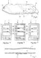
- Figs 1(a)-(b) are a side view and a plan view, respectively, of a package or bag 1 that contains powdery material for use in preparation of a dialysis solution or concentrate to be further diluted to a ready for use dialysis solution, hereinafter collectively referred to as dialysis solution.
- the combined storage and preparation package 1 is shown in a transport/storage state, i.e. before preparation of the dialysis solution.
- the powdery material is separated into two powder groups 2A, 2B of different compositions.
- the powder groups 2A, 2B are spaced from each other, and each powder group 2A, 2B contains either a single dry substance or a combination of compatible dry substances.
- a "dry substance” denotes a substance in solid form. It should be noted that a dry substance may still contain water, e.g. if the water molecules are incorporated in a crystal lattice, so-called water of crystallization.
- the powder groups 2A, 2B are arranged between two sheets or foils 3, 4 that define a single compartment 6, as shown in Fig. 1(b) .
- the sheets 3, 4 are merged to define the compartment 6 by means of a circumferential weld line 7.
- the compartment 6 is collapsed such that opposing sheet portions are brought to engage the respective powder group 2A, 2B.
- the resulting pressing forces serve to immobilize the powder groups 2A, 2B.
- the package 1 further includes a connector 10 which is in fluid communication with the compartment 6.
- the connector 10, which is sealed in the transport/storage state, is adapted for connection to a supply of a solvent, typically water.
- a solvent typically water.
- the package 1 is folded in the transport/storage state, e.g. to facilitate the handling of the package.
- folding the powder groups 2A, 2B and the connector 10 towards each other may serve to protect these protruding parts of the package and to provide a smoother outer contour of the package, thereby reducing the risk for damage during transport/storage.
- the package 1 may be designed and folded such that the most hygroscopic powder group or the powder group with the highest water content is located at the center of the folded package, i.e. is wrapped by the largest number of sheets to impede undesired propagation of moisture within the package.
- Fig. 1(d) illustrates a package 1 in which powder groups 2A, 2B are located in preformed trays 14 in the bottom sheet 4.
- Such a configuration may facilitate the manufacture of the package, since the trays 14 will define the location of each powder group 2A, 2B and may serve to keep the powder groups 2A, 2B in place during manufacture of the package, especially during an evacuation of the compartment 6.
- the provision of trays 14 may also serve to obstruct migration of powder in the transport/storage state.
- Fig. 1(e) illustrates a package 1 in a transport/storage state, in which powder groups 2A-2C are stacked on each other.
- the compartment is evacuated to tightly squeeze the powder groups 2A-2C between opposing sheet portions, whereby the powder groups 2A-2C are immobilized within the single compartment.
- immobilizing the powder groups 2A-2C in relation to each other, and thereby minimizing mixing between the powder groups 2A-2C it might even be possible to arrange incompatible powder groups in contact with each other.
- the package contains three or more powder groups, it may however be preferable to arrange the powder groups so as to optimize the compatibility between neighboring powder groups.
- Fig. 1(e) illustrates a package 1 in a transport/storage state, in which powder groups 2A-2C are stacked on each other.
- the compartment is evacuated to tightly squeeze the powder groups 2A-2C between opposing sheet portions, whereby the powder groups 2A-2C are immobilized within the single compartment.
- a highly hygroscopic powder group 2A may be spaced from a water containing powder group 2C by a less (or non-) hygroscopic powder group 2B with a lower (or no) water content.
- the intermediate powder group 2B will thus serve as a moisture barrier.
- many embodiments of the invention involve an evacuation of the compartment 6 with respect to gases (e.g. air) present in the surroundings of the powder groups.
- gases e.g. air
- the evacuation may also involve removal of gases within the powder groups, e.g. for compacting the powdery material. It is to be noted that depending on implementation the evacuation may or may not reduce the pressure inside the compartment 6 below atmospheric pressure.
- the sheets 3, 4 may be advantageous to establish a sub-atmospheric pressure inside the compartment 6 during the evacuation and to retain this pressure in the transport/storage state so as to retain the engagement between the sheets and the powdery material.
- external means may be used to retain the engagement.
- a shrinkwrap or overwrap (not shown) may be applied onto the exterior of the package to press the sheets against the powdery material.
- the evacuation may establish a required pressure to deform the sheets into engagement with the powder groups. After the deformation, the sub-atmospheric pressure may be released, if the sheets 3, 4 are sufficiently stable to retain the engagement with the powder groups in the absence of sub-atmospheric pressure.
- a sub-atmospheric pressure may be retained in the compartment 6 in the transport/storage state for other reasons, e.g. to reduce migration of moisture between the powder groups and/or to tamper proof the package 1.
- the evacuation may be achieved by actively sucking gases out of the compartment 6 during manufacture, or by applying external forces to press the sheets 3, 4 towards the powder groups and thereby pressing gases out of the compartment 6.
- the compartment 6 may be manufactured in a sub-atmospheric environment, e.g. in a vacuum chamber. Different techniques for manufacturing the package will be exemplified further below with reference to Figs 10-13 .
- Fig. 2(a)-(e) exemplifies the use of an example package 1 for preparation of a dialysis solution.
- the package 1 is delivered at the dialysis site in the transport/storage state, Fig. 2(a) .
- the package 1 is both evacuated and folded.
- the package 1 is transformed into a preparation state by unfolding the package 1 and opening the connector 10 to admit air (or a fluid/solvent) into the compartment 6, Fig. 2(b) .
- the package 1 is then mounted on a stand 20, which may or may not be part of a dialysis machine.
- a stand 20 which may or may not be part of a dialysis machine.
- the package 1 is suspended by threading a suspension hole 18 formed in the periphery of package 1 over a hook 22, such that the powdery material falls down at the bottom of the compartment 6, and the connector 10 is mated within an opening 24 connected to a water supply (not shown).
- the water supply is operated to push a carefully metered volume of water into the compartment 6, whereby the compartment 6 is expanded and the powdery material is dissolved in the water to form the dialysis solution.
- the dialysis solution is extracted from the package 1.
- Fig. 3 illustrates a rectangular package 1 in which powder groups 2A-2D are arranged at the corners of the compartment 6. Thereby, the corner portions may assist the pressing forces exerted by the sheets 4 to restrain any movement of the powdery material.
- the package 1 can be designed with any given number of corners to accommodate a corresponding number of powder groups 2A-2D.
- the package 1 may have the shape of a triangle or a star.
- Fig. 4(a) illustrates a package 1 which is provided with internal partitions 16 that extend from the peripheral weld line 7.
- the partitions 16 define pockets for holding powder groups 2A-2D in the transport/storage state, as illustrated.
- the pockets may be used to facilitate separation of the powder groups 2A-2D when the package 1 is filled and evacuated during manufacture.
- the pockets may also assist the pressing forces exerted by the sheets to prevent mixing between the powder groups 2A-2D.
- Fig. 4(b) illustrates the package of Fig. 4(a) in a preparation state, in which the connector 10 has been opened to admit air or a fluid/solvent into the compartment 6 to release the pressing forces on the powder groups 2A-2D.
- the package In the preparation state, the package is suspended from a suspension hole 18 arranged at one end of the package 1 behind the pockets, i.e. outside the peripheral weld line 7, such that the pockets are emptied by the action of gravity.
- the powder groups fall down into a common mixing zone within the compartment 6.
- the powder groups 2A-2D may be conveyed into the mixing zone before admitting the solvent into the compartment 6, to ensure that all of the powdery material is properly mixed with and dissolved in the solvent and to avoid that some powdery material gets stuck at any corner portion in the compartment 6.
- Fig. 5 is a perspective view of a variant of the package in Fig. 1(d) , where the powdery material is placed in a respective tray 14 which is formed as a permanent depression in the bottom sheet.
- suspension holes 18 and the connector 10 are arranged at opposite ends of the package 1 to ensure that the solvent is admitted into the mixing zone formed at the bottom of the suspended package 1. It can also be noted that the largest tray 14 is arranged at the mixing zone to minimize the provision of corner portions in the mixing zone.
- Figs 6(a)-(c) illustrate the use of a structured sheet surface to facilitate separation of the sheets in the constriction regions.
- the surface structure may be applied to one or both of the sheet portions that form the constriction regions 8, e.g. in the form of an embossed pattern.
- the surface height of the surface structure may be selected so that the spacing between the sheet portions significantly impedes migration of powdery material across the constriction regions 8.
- the pattern is formed as protruding dimples, giving the surface a dotted appearance.
- Fig 6(b) the pattern is formed as elongate ridges.
- ridges are arranged not to form channels between the powder groups. This will allow the height of the ridges to be selected independently of the particle size in the powder groups 2A-2C.
- Fig. 6(c) illustrates yet another example of a surface structure in which short ridges are arranged in mutually offset rows to provide a meandering pattern of channels across the constriction regions 8 between the powder groups 2A-2C. Such a meandering pattern will serve to obstruct migration of powdery material across the constriction regions 8.
- the surface pattern is provided not only in the construction regions 8 but across the entire sheet. This may be preferable for reasons of manufacture, to avoid the need to match the pattern to the locations of the powder groups 2A-2C. Furthermore, the provision of a surface pattern across the major extent of the compartment 6 may serve to facilitate evacuation of the compartment 6 during manufacture, by reducing the tendency for the sheets to be sucked together locally within the compartment 6 by the forces of evacuation.
- the evacuation of air from the compartment 6 may be done through a separate evacuation port in one of the sheets, which port is closed after the evacuation by e.g. welding or application of a tape.
- the evacuation port may be automatically closed after evacuation by the resulting pressure difference.
- Such an evacuation port may be implemented as a check valve.
- Fig. 7 illustrates a check valve 70 which is integrated into one of the sheets (here, the bottom sheet 4) that define the compartment 6.
- Figs 8(a)-(b) are perspective and section views, respectively, of a connector 10 with an integrated check valve function.
- one end of the connector has a flange 80 which is arranged for mounting, e.g. by welding or gluing, in alignment with an opening in a wall portion of the compartment.
- a membrane 82 is arranged to seal the opening of the connector 10.
- the membrane 82 is further arranged to be penetrated at connection of a standard connector (not shown) on a line set in fluid communication with e.g. a dialysis machine or a catheter for peritoneal dialysis.
- a recess 83 for an o-ring 84 is formed in the outer periphery of the connector 10.
- the o-ring 84 is covering (and sealing) a small hole 85 which is in fluid communication with the interior of the connector 10 and thus with the compartment.
- the combination of the o-ring 84 and the hole 85 has the function of a check valve. When a suction is applied on the outside of the connector 10, the o-ring 84 moves away from the hole 85 to allow air to be sucked out of the compartment, and when the negative pressure is removed the o-ring 84 closes the hole 85 and prevents air from re-entering the compartment.
- Fig. 9 illustrates a technique to facilitate evacuation of the compartment via an evacuation port, be it the connector 10 (as shown) or a separate opening.
- Fig. 9 illustrates an embodiment of the package 1 before evacuation, where a pull tab 4A is attached to the sheet portion opposite to the evacuation port 10.
- the pull tab 4A may be used to ensure that the sheet portion is not sucked onto the evacuation port 10 during the evacuation, by applying a force (indicated by arrow 90) to pull the tab 4A away from the evacuation port 10.
- Many equivalent structures are readily available to the skilled person. For example, a suction may be applied to the outside of sheet portion to pull it away from the evacuation port 10.
- the provision of an internal surface structure on one or both of the sheets 3, 4 may also serve to facilitate proper evacuation of the compartment 6.
- Fig. 10 is a schematic illustration of an exemplifying production plant in which the packages 1 are formed from two rolls 101, 102 of foil and filled with powders in separate trays (cf. Figs 1(d) and 5 ).
- foils 101A, 102A coming from two rolls pass a number of processing steps/sites1002-1018.
- the feeding directions of the foils 101A, 102A are indicated by arrows F1, F2.
- step 1002 in the lower foil track trays are formed in the foil 102A. This may be done by thermoforming, e.g.
- step 1004 the different powder groups are measured/weighed and dosed into the preformed trays.
- the upper foil 101A is prepared by punching (step 1006) a hole and attaching/welding (step 1008) a connector 10 to the material surrounding the hole.
- the two foil tracks are then joined together and welded (step 1010) at the periphery to define and seal off the compartment containing the powder groups.
- step 1012 the circumference of the package and suspension holes are cut.
- the processed package is then, in step 1014, exposed to a sub-atmospheric pressure in either a closed environment, e.g.
- the package 1 is folded (step 1016) and packed (step 1018) into a cardboard box for delivery to customer.
- the connector 10 is folded in against the powder side to be protected during transport.
- step 1014 air (step 1014) is evacuated after the compartment is defined with a final sealing weld (step 1010), since this may make it easier to keep the powder groups in place during manufacture, compared to a production method where the compartment is evacuated before being finally defined in step 1010.
- Fig. 11 is a schematic illustration of an alternative production plant for manufacturing the packages 1.
- a foil 101A coming from a roll 101 passes a number of processing steps/sites.
- the feeding direction of the foil 101A is indicated by arrow F1.
- the foil 101A is folded along its extent to form two overlapping sheet portions.
- the compartment is partially defined by means of a welding station 110 which forms a transverse weld line 7' across the overlapping sheet portions, while leaving the upper end portion of the compartment open.
- the connector 10 is attached to one of the sheet portions.
- temporary pockets are defined in the compartment and the powder groups 2A-2C are carefully metered into the pockets via the open upper end portion, by means of a metering station 112.
- a weld line 7" is formed in the upper end portion, by means of a welding station 114, to seal the compartment.
- the compartment is also evacuated, either via the connector 10 after sealing, or before/during sealing by performing steps 1106 and 1108 in a vacuum chamber (not shown).
- the circumference of the package 1 is cut, and in step 1112 the package 1 is processed for transport, e.g. by folding and packaging.
- Fig. 12 is an alternative view of the plant in Fig. 11 , to illustrate the step 1106 of defining the temporary pockets in greater detail.
- two drive belts 118A, 118B are arranged on opposing sides of the folded foil 101A, where each drive belt 118A, 118B is arranged on two rotatable drive wheels 120, 122 and supports a number of transverse protrusions or fingers 124.
- the opposing drive belts 118A, 118B are rotated in synchronization such that the fingers 124 are made to abut against each other at a number of locations along the compartment.
- the abutment between the fingers 124 is maintained also during the welding and evacuation step 1108.
- only one of the drive belts is provided with fingers 124, whereas the other drive belt provides a flat surface to support the folded foil 101A against the pressing action of the fingers 124.
- step 1108 may be modified to form permanent dividers in the compartment, e.g. by the fingers 124 being exchanged for welding jaws that form weld lines that extend from the closed lower end portion into the compartment to define pockets therein (cf. Fig. 4(a) ).
- Fig. 13 illustrates yet another alternative way of manufacturing the packages.
- the compartment is formed with an open end portion, e.g. by combining two foils as in Fig. 10 or by folding a single foil as in Fig. 11 .
- the combined foil material is then folded such that the fold lines 12 define pockets in the compartment, as shown in Fig. 13 .
- the powdery groups are metered into the respective pockets.
- the compartment is then evacuated, e.g. by sealing the open end portion, unfolding the package and applying a sub-atmospheric pressure via the connector 10, or by sealing the open end portion in a vacuum chamber.
- the folding may be carried out on a continuous web of material (e.g. a foil track) or on units that are separated from such a web.
- the package may include more than one compartment that immobilizes plural powder groups and/or the package 1 may include one or more further compartments, of any type, that contains one powder group each.
- the compartments of the package may be separated using conventional dividers that are ruptured either manually or automatically, e.g. by application of fluid pressure.
- the compartment may comprise an inlet connector and an outlet connector, such that the solvent can be driven to flow through the compartment, where the solvent may be continuously driven to flow through the compartment, possibly using recirculation, until the powdery material is dissolved.
- the solvent is admitted via the inlet connector to mix with and dissolve the powdery material, whereupon the prepared medical solution is expelled via the outlet connector.
- the mixing and dissolution of the powdery material takes place exclusively outside of the compartment.
- the powder groups may be poured or sucked out of the compartment to be mixed with the solvent.
- the connector may be omitted from the package. It is also conceivable that the mixing with the solvent takes place in a separate compartment within the package.
- a sub-atmospheric pressure or "vacuum" in the compartment serves to significantly improve the shelf life of the powdery material, especially for substances that are degraded by the presence of moisture.
- a package for storing a powdery material comprises a compartment and powdery material in the compartment, with a sub-atmospheric pressure being established within the compartment.
- the opposing wall portions of the compartment are brought and/or held into engagement with the powdery material, e.g.
- the package comprises a connector for selectively admitting a fluid into the package for expanding the compartment and enabling mixing of the powdery material with the solvent as part of a process for preparing a medical solution.
Landscapes
- Health & Medical Sciences (AREA)
- Heart & Thoracic Surgery (AREA)
- Urology & Nephrology (AREA)
- Life Sciences & Earth Sciences (AREA)
- Animal Behavior & Ethology (AREA)
- General Health & Medical Sciences (AREA)
- Public Health (AREA)
- Veterinary Medicine (AREA)
- Emergency Medicine (AREA)
- Hematology (AREA)
- Vascular Medicine (AREA)
- Engineering & Computer Science (AREA)
- Anesthesiology (AREA)
- Biomedical Technology (AREA)
- Pharmacology & Pharmacy (AREA)
- Physics & Mathematics (AREA)
- Fluid Mechanics (AREA)
- External Artificial Organs (AREA)
- Medical Preparation Storing Or Oral Administration Devices (AREA)
Claims (22)
- Packung, die Pulvermaterial unterbringt, das mit einem Lösemittel vermischt werden soll, um eine medizinische Lösung auszubilden, die Packung Folgendes umfassend:eine Kammer (6), die mindestens teilweise durch zwei gegenüberliegende Wandabschnitte definiert ist und das Pulvermaterial in der Form von mindestens zwei distinkten Mengen (2A bis 2D) Pulvermaterial verschiedener Zusammensetzungen enthält, wobei die Mengen (2A bis 2D) Pulvermaterial in der Kammer (6) voneinander beabstandet sind und die gegenüberliegenden Wandabschnitte mit dem Pulvermaterial in Formschluss gebracht sind, um die Mengen (2A bis 2D) Pulvermaterial so zu immobilisieren; undeinen Verbinder (10) zum wahlweisen Einlassen eines Fluids in die Packung zum Ausdehnen der Kammer (6) und Ermöglichen eines Vermischens der Mengen (2A bis 2D) Pulvermaterial mit dem Lösemittel in der Kammer (6) als Teil eines Prozesses zum Zubereiten der medizinischen Lösung,wodurch mindestens zwei der beabstandeten Mengen durch einen Verengungsbereich (8) getrennt sind, dadurch gekennzeichnet, dass in dem Verengungsbereich zwei gegenüberliegende Schichten (3, 4), die zwischen ihnen mindestens teilweise die Kammer (6) definieren, in enger räumlicher Nähe zueinander sind, ohne fest aneinander angebracht zu sein, wobei der Abstand der gegenüberliegenden Schichten (3, 4) in dem Verengungsbereich kleiner ist als ein effektiver minimaler Durchmesser des Pulvermaterials.
- Packung nach Anspruch 1, wobei mindestens einer der gegenüberliegenden Wandabschnitte in den Formschluss deformiert ist.
- Packung nach Anspruch 1 oder 2, wobei mindestens einer der gegenüberliegenden Wandabschnitte aus flexiblem Material gemacht ist.
- Packung nach Anspruch 1, 2 oder 3, wobei die gegenüberliegenden Wandabschnitte durch Evakuierung von Gas aus der Kammer (6) in den Formschluss gebracht werden.
- Packung nach Anspruch 4, wobei die Kammer (6) einen Unteratmosphärendruck hält.
- Packung nach Anspruch 4 oder 5, wobei die Kammer (6) derartig evakuiert ist, dass das Pulvermaterial mindestens teilweise verdichtet ist.
- Packung nach einem der vorhergehenden Ansprüche, die gefaltet ist, um so eine Falte oder Biegung (12) in dem Verengungsbereich (8) auszubilden.
- Packung nach einem der vorhergehenden Ansprüche, weiterhin umfassend ein Mittel zum Reduzieren einer Anhaftung zwischen den Schichten (3, 4) in dem Verengungsbereich (8).
- Packung nach Anspruch 8, wobei das Mittel zum Reduzieren einer Anhaftung eine dreidimensionale Oberflächenstruktur umfasst, die dem Verengungsbereich (8) auf mindestens einer der Schichten (3, 4) gegenüber steht.
- Packung nach Anspruch 9, wobei die Oberflächenstruktur eine Tiefe von weniger als 50 µm, vorzugsweise von weniger als 10 µm aufweist.
- Packung nach Anspruch 9 oder 10, wobei die Oberflächenstruktur durch längliche Rippen definiert ist, die sich im Wesentlichen senkrecht zu einer Trennungsrichtung zwischen den beabstandeten Mengen (2A bis 2D) erstrecken.
- Packung nach einem der Ansprüche 8 bis 11, wobei das Mittel zum Reduzieren einer Anhaftung eine jeweilige Zusammensetzung der Schichten (3, 4) zur geringen gegenseitigen Anhaftung umfasst.
- Packung nach einem der vorhergehenden Ansprüche, wobei mindestens eine der Mengen (2A bis 2D) Pulvermaterial in einer vordefinierten Tasche innerhalb der Kammer (6) angeordnet ist.
- Packung nach Anspruch 13, wobei die Tasche mindestens teilweise durch eine interne Trennwand (16) definiert ist, die sich aus einem geschlossenen Perimeterabschnitt der Kammer (6) in die Kammer (6) erstreckt.
- Packung nach Anspruch 13 oder 14, wobei die Tasche mindestens teilweise durch einen internen Eckabschnitt an dem Perimeter der Kammer (6) definiert ist.
- Packung nach Anspruch 13, wobei die Tasche als eine schalenförmige Deformation (14) in einer der gegenüberliegenden Wandabschnitte ausgebildet ist.
- Packung nach einem der vorhergehenden Ansprüche, weiterhin ein Rückschlagventil (70; 84, 85) in Fluidverbindung mit der Kammer (6) umfassend, um eine Evakuierung der Kammer (6) zu ermöglichen.
- Packung nach Anspruch 17, wobei das Rückschlagventil (84, 85) mit dem Verbinder (10) integriert ist.
- Packung nach einem vorhergehenden Anspruch, wobei das Fluid eines aus einem Gas und dem Lösemittel ist.
- Packung nach einem vorhergehenden Anspruch, wobei die medizinische Lösung eine aus einem Dialysekonzentrat, einer Dialyselösung, einer Infusionslösung, einer Nährstofflösung, einer Ersatzlösung und einer Plasmaexpanderlösung ist.
- Verfahren zum Herstellen einer Packung (1), die Pulvermaterial unterbringt, das mit einem Lösemittel vermischt werden soll, um eine medizinische Lösung auszubilden, das Verfahren Folgendes umfassend:Anordnen des Pulvermaterials in einer Kammer (6), die mindestens teilweise durch zwei gegenüberliegende Wandabschnitte definiert ist, wobei das Pulvermaterial in der Form von mindestens zwei distinkten Mengen (2A bis 2D) Pulvermaterial verschiedener Zusammensetzungen angeordnet ist, wobei die Mengen (2A bis 2D) Pulvermaterial in der Kammer (6) voneinander beabstandet sind;Bereitstellen eines Verbinders (10) zum wahlweisen Einlassen eines Fluids in die Packung (1) zum Ausdehnen der Kammer (6) und Ermöglichen eines Vermischens der Mengen (2A bis 2D) Pulvermaterial mit dem Lösemittel in der Kammer (6) als Teil eines Prozesses zum Zubereiten der medizinischen Lösung; undBringen der gegenüberliegenden Wandabschnitte in Formschluss mit dem Pulvermaterial (2A bis 2D), um so die Mengen (2A bis 2D) Pulvermaterial zu immobilisieren,Trennen mindestens zwei der beabstandeten Mengen durch einen Verengungsbereich (8), dadurch gekennzeichnet, dass in dem Verengungsbereich zwei gegenüberliegende Schichten (3, 4), die zwischen ihnen mindestens teilweise die Kammer (6) definieren, in enge räumliche Nähe zueinander gebracht werden, ohne fest aneinander angebracht zu sein, wobei der Abstand der gegenüberliegenden Schichten (3, 4) in dem Verengungsbereich kleiner ist als ein effektiver minimaler Durchmesser des Pulvermaterials.
- Verfahren zum Zubereiten einer medizinischen Lösung, das Verfahren Folgendes umfassend:Erhalten einer Packung (1) nach einem der Ansprüche 1 bis 20;Verbinden des Verbinders (10) der Packung (1) mit einer Quelle eines Lösemittels; undwahlweises Einlassen des Lösemittels in die Packung (1), wodurch die Kammer (6) ausgedehnt wird und das Lösemittel mit den Mengen (2A bis 2D) Pulvermaterial innerhalb der Kammer (6) als Teil eines Prozesses zum Zubereiten der medizinischen Lösung vermischt.
Priority Applications (1)
| Application Number | Priority Date | Filing Date | Title |
|---|---|---|---|
| PL11727963T PL2585023T3 (pl) | 2010-06-23 | 2011-06-20 | Przygotowanie roztworów medycznych ze sproszkowanego materiału |
Applications Claiming Priority (3)
| Application Number | Priority Date | Filing Date | Title |
|---|---|---|---|
| SE1050684 | 2010-06-23 | ||
| US35800910P | 2010-06-24 | 2010-06-24 | |
| PCT/EP2011/060255 WO2011161064A1 (en) | 2010-06-23 | 2011-06-20 | Preparation of medical solutions from powdery material |
Publications (2)
| Publication Number | Publication Date |
|---|---|
| EP2585023A1 EP2585023A1 (de) | 2013-05-01 |
| EP2585023B1 true EP2585023B1 (de) | 2019-07-17 |
Family
ID=44584133
Family Applications (1)
| Application Number | Title | Priority Date | Filing Date |
|---|---|---|---|
| EP11727963.8A Active EP2585023B1 (de) | 2010-06-23 | 2011-06-20 | Zubereitung von medizinischen lösungen aus pulvermaterial |
Country Status (10)
| Country | Link |
|---|---|
| US (1) | US9138380B2 (de) |
| EP (1) | EP2585023B1 (de) |
| JP (1) | JP5937069B2 (de) |
| KR (1) | KR101800053B1 (de) |
| CN (1) | CN102946840B (de) |
| AU (1) | AU2011269117B2 (de) |
| BR (1) | BR112012032770A2 (de) |
| CA (1) | CA2802446C (de) |
| PL (1) | PL2585023T3 (de) |
| WO (1) | WO2011161064A1 (de) |
Families Citing this family (28)
| Publication number | Priority date | Publication date | Assignee | Title |
|---|---|---|---|---|
| JP2997246B1 (ja) | 1998-08-11 | 2000-01-11 | 日本たばこ産業株式会社 | シガレット製造機の圧縮成形装置 |
| US9585810B2 (en) | 2010-10-14 | 2017-03-07 | Fresenius Medical Care Holdings, Inc. | Systems and methods for delivery of peritoneal dialysis (PD) solutions with integrated inter-chamber diffuser |
| WO2012078696A2 (en) | 2010-12-06 | 2012-06-14 | Aktivpak, Inc. | Aseptic cartridge and dispenser arrangement |
| US20120199205A1 (en) | 2011-02-03 | 2012-08-09 | Fresenius Medical Care Deutschland Gmbh | System for preparing a medical fluid and method for preparing a medical fluid |
| CN103619372A (zh) | 2011-03-23 | 2014-03-05 | 纳科斯达格医药股份有限公司 | 腹膜透析系统、装置和方法 |
| US9861733B2 (en) | 2012-03-23 | 2018-01-09 | Nxstage Medical Inc. | Peritoneal dialysis systems, devices, and methods |
| FR2975302B1 (fr) | 2011-05-18 | 2013-05-10 | Fresenius Medical Care De Gmbh | Connecteur pour recipient de dialyse, recipient muni d'un tel connecteur, procede de fabrication et de remplissage de tels connecteurs et recipients |
| FR2978914B1 (fr) * | 2011-08-11 | 2013-08-16 | Fresenius Medical Care De Gmbh | Recipient pour dialyse |
| ITBO20130267A1 (it) * | 2013-05-28 | 2014-11-29 | Bellco Srl | Metodo per produrre una sacca contenente bicarbonato in polvere |
| WO2015000666A1 (en) | 2013-07-05 | 2015-01-08 | Gambro Lundia Ab | Packaging of powdery material for preparation of a medical solution |
| DE102013108082A1 (de) * | 2013-07-29 | 2015-01-29 | B. Braun Avitum Ag | Vorrichtung zum Herstellen einer Lösung, inbesondere in/an einer Dialysemaschine |
| US10478544B2 (en) | 2014-09-25 | 2019-11-19 | Nxstage Medical, Inc. | Medicament preparation and treatment devices, methods, and systems |
| JP6314868B2 (ja) * | 2015-02-12 | 2018-04-25 | 株式会社ダイフク | 服用物包装体 |
| JP6912387B2 (ja) * | 2015-05-27 | 2021-08-04 | トリオメド エービーTriomed Ab | 吸着透析を実行するためのカートリッジ、方法、および、装置 |
| US9814819B2 (en) * | 2015-06-15 | 2017-11-14 | Fresenius Medical Care Holdings, Inc. | Dialysis machines with integral salt solution chambers and related methods |
| EP3487554A1 (de) * | 2016-07-25 | 2019-05-29 | Medtronic Inc. | Infusathalter |
| EP3554710A1 (de) * | 2016-12-19 | 2019-10-23 | Cambtek Limited | Verbesserte extraktionsvorrichtung |
| EP3641850B1 (de) | 2017-06-24 | 2024-10-09 | NxStage Medical Inc. | Systeme zur herstellung von peritonealdialyseflüssigkeit |
| USD913807S1 (en) | 2017-12-20 | 2021-03-23 | Intercontinental Great Brands Llc | Confectionery packaging |
| USD856630S1 (en) | 2017-12-20 | 2019-08-20 | Intercontinental Great Brands Llc | Confection |
| KR102385105B1 (ko) * | 2018-02-27 | 2022-04-08 | 삼성전자주식회사 | 크랙 검출용 칩 및 이를 이용한 크랙 검출 방법 |
| CA3296263A1 (en) | 2018-02-28 | 2026-03-02 | Nxstage Medical, Inc. | Fluid preparation and treatment devices, methods, and systems |
| USD953886S1 (en) * | 2018-05-11 | 2022-06-07 | Intercontinental Great Brands Llc | Confectionery packaging |
| USD862247S1 (en) | 2018-06-25 | 2019-10-08 | Intercontinental Great Brands Llc | Confectionery packaging |
| US11419791B2 (en) | 2018-07-05 | 2022-08-23 | Fresenius Medical Care Holdings, Inc. | Flexible container systems and nozzles, and related methods |
| DE102018129480A1 (de) * | 2018-11-22 | 2020-05-28 | Fresenius Medical Care Deutschland Gmbh | Vorrichtung und Verfahren zum Dosieren von pulverförmigen Stoffen und Verpackung zur Aufnahme von pulverförmigen Stoffen für eine Vorrichtung zum Dosieren von pulverförmigen Stoffen |
| FR3089126B1 (fr) | 2018-11-30 | 2020-12-18 | Fresenius Medical Care Deutschland Gmbh | Poche pour concentré solide |
| USD1037014S1 (en) | 2020-01-07 | 2024-07-30 | Perfetti Van Melle Benelux B.V. | Confectionery packaging |
Family Cites Families (36)
| Publication number | Priority date | Publication date | Assignee | Title |
|---|---|---|---|---|
| US3722833A (en) | 1969-11-15 | 1973-03-27 | Inoue Japax Res | Method of spatulating packaged dental filling |
| US4237935A (en) * | 1978-12-14 | 1980-12-09 | Eaton Corporation | Hydraulic pressure relief valve and fluid isolator |
| US4549565A (en) * | 1984-03-05 | 1985-10-29 | Bs&B Safety Systems, Inc. | Reclosing rupture disk assembly |
| US4664891A (en) | 1984-07-23 | 1987-05-12 | Renal Systems, Inc. | Dialysis solution preparation from prepackaged dry chemicals |
| US4684025A (en) * | 1986-01-30 | 1987-08-04 | The Procter & Gamble Company | Shaped thermoformed flexible film container for granular products and method and apparatus for making the same |
| US5217854A (en) | 1990-05-10 | 1993-06-08 | Fuji Photo Film Co., Ltd. | Vacuum packaged color developing composition |
| US5385564A (en) * | 1992-10-05 | 1995-01-31 | Fresenius Usa, Inc. | System for preparation and use of dialysis solution |
| CN1128005A (zh) * | 1994-03-15 | 1996-07-31 | 株式会社大塚制药工场 | 防污染密封膜及其制品 |
| JPH07300161A (ja) | 1994-04-28 | 1995-11-14 | Kanae:Kk | 複数の収納部を有する包装体及び包装体の製造方法 |
| US6655837B2 (en) | 1998-05-29 | 2003-12-02 | Toyo Seikan Kaisha, Ltd. | Pouch having a branched chamber |
| US6605214B1 (en) * | 1999-03-03 | 2003-08-12 | Prismedical Corporation | Devices for preparing hemodialysis solutions |
| WO2000051705A1 (en) | 1999-03-03 | 2000-09-08 | Prismedical Corporation | Methods and devices for preparing hemodialysis solutions |
| JP2001045470A (ja) | 1999-07-27 | 2001-02-16 | Ichikoh Ind Ltd | 車両用確認装置 |
| JP2001046470A (ja) * | 1999-08-12 | 2001-02-20 | Nikkiso Co Ltd | 容器入り薬剤 |
| US20050194060A1 (en) | 2004-03-03 | 2005-09-08 | Vincent Houwaert | Peelable seal closure assembly |
| US6831051B2 (en) * | 2000-04-28 | 2004-12-14 | The Procter & Gamble Company | Pouched compositions |
| GB2361687A (en) | 2000-04-28 | 2001-10-31 | Procter & Gamble | Layered water soluble pouch for detergents |
| JP2001328676A (ja) * | 2000-05-24 | 2001-11-27 | Nikkiso Co Ltd | 透析用剤の容器 |
| JP2001335069A (ja) * | 2000-05-26 | 2001-12-04 | Nikkiso Co Ltd | 透析用剤の容器 |
| DE10056212B4 (de) | 2000-11-13 | 2005-08-18 | 3M Espe Ag | Vorrichtung zum Lagern und Ausbringen von fließfähigen Zusammensetzungen, Verfahren zur Herstellung und Verwendung der Vorrichtung |
| JP4467812B2 (ja) | 2001-02-06 | 2010-05-26 | 大日本印刷株式会社 | 包装袋及びその製造方法 |
| DE10152105A1 (de) * | 2001-10-23 | 2003-05-08 | Fresenius Medical Care De Gmbh | Behältnis zur Verwendung in der Dialyse |
| US20030111492A1 (en) | 2001-12-19 | 2003-06-19 | Pramod Gupta | Packaging system for separately storing and dispensing together separate medication components |
| DE10162959B4 (de) * | 2001-12-20 | 2017-10-12 | Fresenius Medical Care Deutschland Gmbh | Behälter enthaltend mindestens zwei Feststoffe und dessen Verwendung |
| WO2004041107A2 (de) | 2002-11-02 | 2004-05-21 | Kettenbach Gmbh & Co. Kg | Vorrichtung zum lagern und ausbringen viskoser substanzen |
| AR037133A1 (es) * | 2003-02-04 | 2004-10-27 | Fresenius Medical Care Argentina | Bolsa bicompartimentada para maquinas de hemodialisis y su procedimiento de fabricacion |
| WO2004080369A1 (fr) * | 2003-03-10 | 2004-09-23 | Lei Wang | Sac a depression pour poudre a injecter et raccord a cet effet |
| US20060127540A1 (en) * | 2004-12-13 | 2006-06-15 | Keckeis Edward J | Package for storing omelet ingredients |
| JP4414353B2 (ja) | 2005-02-22 | 2010-02-10 | 本多プラス株式会社 | 複室容器 |
| US20060196784A1 (en) * | 2005-03-03 | 2006-09-07 | Murray R C | Multi-compartment flexible pouch |
| JP4749057B2 (ja) | 2005-06-30 | 2011-08-17 | 三井化学株式会社 | 複室輸液容器及びその製造方法 |
| EP2035059B1 (de) * | 2006-06-15 | 2015-11-18 | Metpro AB | Behälter, system und verfahren zur bereitstellung einer lösung |
| CA2659853A1 (en) * | 2006-08-07 | 2008-02-21 | The Glad Products Company | Vacuum storage bag |
| US20080149668A1 (en) | 2006-12-20 | 2008-06-26 | Johnson Lars S | Collapsible bag for dispensing liquids, method of manufacturing, and method of use thereof |
| GB0700920D0 (en) * | 2007-01-18 | 2007-02-28 | Reckitt Benckiser Nv | Dosage element and a method of manufacturing a dosage element |
| US20110210143A1 (en) * | 2008-11-12 | 2011-09-01 | Teventi, Llc | Beverage pouch and method of use |
-
2011
- 2011-06-20 EP EP11727963.8A patent/EP2585023B1/de active Active
- 2011-06-20 JP JP2013515842A patent/JP5937069B2/ja active Active
- 2011-06-20 KR KR1020137001845A patent/KR101800053B1/ko not_active Expired - Fee Related
- 2011-06-20 PL PL11727963T patent/PL2585023T3/pl unknown
- 2011-06-20 AU AU2011269117A patent/AU2011269117B2/en not_active Ceased
- 2011-06-20 WO PCT/EP2011/060255 patent/WO2011161064A1/en not_active Ceased
- 2011-06-20 CA CA2802446A patent/CA2802446C/en active Active
- 2011-06-20 US US13/805,557 patent/US9138380B2/en active Active
- 2011-06-20 BR BR112012032770A patent/BR112012032770A2/pt not_active Application Discontinuation
- 2011-06-20 CN CN201180031197.XA patent/CN102946840B/zh active Active
Non-Patent Citations (1)
| Title |
|---|
| None * |
Also Published As
| Publication number | Publication date |
|---|---|
| US20130190681A1 (en) | 2013-07-25 |
| CA2802446A1 (en) | 2011-12-29 |
| AU2011269117B2 (en) | 2014-03-06 |
| KR20130121082A (ko) | 2013-11-05 |
| US9138380B2 (en) | 2015-09-22 |
| CA2802446C (en) | 2018-03-06 |
| EP2585023A1 (de) | 2013-05-01 |
| CN102946840A (zh) | 2013-02-27 |
| PL2585023T3 (pl) | 2019-12-31 |
| AU2011269117A1 (en) | 2013-02-07 |
| BR112012032770A2 (pt) | 2016-12-20 |
| CN102946840B (zh) | 2015-03-11 |
| JP2013533768A (ja) | 2013-08-29 |
| JP5937069B2 (ja) | 2016-06-22 |
| KR101800053B1 (ko) | 2017-11-21 |
| WO2011161064A1 (en) | 2011-12-29 |
Similar Documents
| Publication | Publication Date | Title |
|---|---|---|
| CA2802446C (en) | Preparation of medical solutions from powdery material | |
| US9198830B2 (en) | Bag with a flexurally rigid plastic part welded into it | |
| US20080149515A1 (en) | Container containing at least two solids and use thereof | |
| EP3654908A1 (de) | Geschlossene gefriertrocknung durch endsterilisationsfiltration in einem behälter | |
| US10130745B2 (en) | Packaging of powdery material for preparation of a medical solution | |
| JP2022509808A (ja) | 可撓性容器の製造 | |
| JP2022510864A (ja) | 凍結乾燥物容器および点滴キット | |
| EP2808042B1 (de) | Beutel mit Bicarbonatpulver | |
| EP1838272B1 (de) | Medizinischer flüssigkeitsbehälter und ein präparat enthaltender medizinischer flüssigkeitsbehälter | |
| ES2741423T3 (es) | Preparación de soluciones médicas a partir de material pulverulento | |
| CN101083971B (zh) | 医用液体容器和含制剂的医用液体容器 | |
| JP5633051B2 (ja) | 医療用複室容器及びその使用方法 | |
| KR102645146B1 (ko) | 개봉이 편리하고 액상 음용이 용이한 포장 파우치 | |
| HK40057197A (en) | Lyophilisate container and infusion kit | |
| CN112867522A (zh) | 用于注射装置的可变形盒 |
Legal Events
| Date | Code | Title | Description |
|---|---|---|---|
| PUAI | Public reference made under article 153(3) epc to a published international application that has entered the european phase |
Free format text: ORIGINAL CODE: 0009012 |
|
| 17P | Request for examination filed |
Effective date: 20130123 |
|
| AK | Designated contracting states |
Kind code of ref document: A1 Designated state(s): AL AT BE BG CH CY CZ DE DK EE ES FI FR GB GR HR HU IE IS IT LI LT LU LV MC MK MT NL NO PL PT RO RS SE SI SK SM TR |
|
| DAX | Request for extension of the european patent (deleted) | ||
| STAA | Information on the status of an ep patent application or granted ep patent |
Free format text: STATUS: EXAMINATION IS IN PROGRESS |
|
| 17Q | First examination report despatched |
Effective date: 20170221 |
|
| REG | Reference to a national code |
Ref country code: DE Ref legal event code: R079 Ref document number: 602011060488 Country of ref document: DE Free format text: PREVIOUS MAIN CLASS: A61J0001200000 Ipc: A61M0001280000 |
|
| GRAP | Despatch of communication of intention to grant a patent |
Free format text: ORIGINAL CODE: EPIDOSNIGR1 |
|
| STAA | Information on the status of an ep patent application or granted ep patent |
Free format text: STATUS: GRANT OF PATENT IS INTENDED |
|
| RIC1 | Information provided on ipc code assigned before grant |
Ipc: A61J 1/20 20060101ALI20181130BHEP Ipc: A61M 1/16 20060101ALI20181130BHEP Ipc: A61M 1/28 20060101AFI20181130BHEP Ipc: B65D 30/24 20060101ALI20181130BHEP Ipc: B65D 81/20 20060101ALI20181130BHEP Ipc: B65D 81/18 20060101ALI20181130BHEP |
|
| INTG | Intention to grant announced |
Effective date: 20190109 |
|
| GRAS | Grant fee paid |
Free format text: ORIGINAL CODE: EPIDOSNIGR3 |
|
| GRAA | (expected) grant |
Free format text: ORIGINAL CODE: 0009210 |
|
| STAA | Information on the status of an ep patent application or granted ep patent |
Free format text: STATUS: THE PATENT HAS BEEN GRANTED |
|
| AK | Designated contracting states |
Kind code of ref document: B1 Designated state(s): AL AT BE BG CH CY CZ DE DK EE ES FI FR GB GR HR HU IE IS IT LI LT LU LV MC MK MT NL NO PL PT RO RS SE SI SK SM TR |
|
| REG | Reference to a national code |
Ref country code: GB Ref legal event code: FG4D |
|
| REG | Reference to a national code |
Ref country code: CH Ref legal event code: EP |
|
| REG | Reference to a national code |
Ref country code: IE Ref legal event code: FG4D |
|
| REG | Reference to a national code |
Ref country code: DE Ref legal event code: R096 Ref document number: 602011060488 Country of ref document: DE |
|
| REG | Reference to a national code |
Ref country code: AT Ref legal event code: REF Ref document number: 1155256 Country of ref document: AT Kind code of ref document: T Effective date: 20190815 |
|
| REG | Reference to a national code |
Ref country code: NL Ref legal event code: MP Effective date: 20190717 |
|
| REG | Reference to a national code |
Ref country code: LT Ref legal event code: MG4D |
|
| REG | Reference to a national code |
Ref country code: AT Ref legal event code: MK05 Ref document number: 1155256 Country of ref document: AT Kind code of ref document: T Effective date: 20190717 |
|
| PG25 | Lapsed in a contracting state [announced via postgrant information from national office to epo] |
Ref country code: FI Free format text: LAPSE BECAUSE OF FAILURE TO SUBMIT A TRANSLATION OF THE DESCRIPTION OR TO PAY THE FEE WITHIN THE PRESCRIBED TIME-LIMIT Effective date: 20190717 Ref country code: PT Free format text: LAPSE BECAUSE OF FAILURE TO SUBMIT A TRANSLATION OF THE DESCRIPTION OR TO PAY THE FEE WITHIN THE PRESCRIBED TIME-LIMIT Effective date: 20191118 Ref country code: HR Free format text: LAPSE BECAUSE OF FAILURE TO SUBMIT A TRANSLATION OF THE DESCRIPTION OR TO PAY THE FEE WITHIN THE PRESCRIBED TIME-LIMIT Effective date: 20190717 Ref country code: BG Free format text: LAPSE BECAUSE OF FAILURE TO SUBMIT A TRANSLATION OF THE DESCRIPTION OR TO PAY THE FEE WITHIN THE PRESCRIBED TIME-LIMIT Effective date: 20191017 Ref country code: NL Free format text: LAPSE BECAUSE OF FAILURE TO SUBMIT A TRANSLATION OF THE DESCRIPTION OR TO PAY THE FEE WITHIN THE PRESCRIBED TIME-LIMIT Effective date: 20190717 Ref country code: LT Free format text: LAPSE BECAUSE OF FAILURE TO SUBMIT A TRANSLATION OF THE DESCRIPTION OR TO PAY THE FEE WITHIN THE PRESCRIBED TIME-LIMIT Effective date: 20190717 Ref country code: SE Free format text: LAPSE BECAUSE OF FAILURE TO SUBMIT A TRANSLATION OF THE DESCRIPTION OR TO PAY THE FEE WITHIN THE PRESCRIBED TIME-LIMIT Effective date: 20190717 Ref country code: AT Free format text: LAPSE BECAUSE OF FAILURE TO SUBMIT A TRANSLATION OF THE DESCRIPTION OR TO PAY THE FEE WITHIN THE PRESCRIBED TIME-LIMIT Effective date: 20190717 Ref country code: NO Free format text: LAPSE BECAUSE OF FAILURE TO SUBMIT A TRANSLATION OF THE DESCRIPTION OR TO PAY THE FEE WITHIN THE PRESCRIBED TIME-LIMIT Effective date: 20191017 |
|
| REG | Reference to a national code |
Ref country code: ES Ref legal event code: FG2A Ref document number: 2741423 Country of ref document: ES Kind code of ref document: T3 Effective date: 20200211 |
|
| PG25 | Lapsed in a contracting state [announced via postgrant information from national office to epo] |
Ref country code: IS Free format text: LAPSE BECAUSE OF FAILURE TO SUBMIT A TRANSLATION OF THE DESCRIPTION OR TO PAY THE FEE WITHIN THE PRESCRIBED TIME-LIMIT Effective date: 20191117 Ref country code: RS Free format text: LAPSE BECAUSE OF FAILURE TO SUBMIT A TRANSLATION OF THE DESCRIPTION OR TO PAY THE FEE WITHIN THE PRESCRIBED TIME-LIMIT Effective date: 20190717 Ref country code: GR Free format text: LAPSE BECAUSE OF FAILURE TO SUBMIT A TRANSLATION OF THE DESCRIPTION OR TO PAY THE FEE WITHIN THE PRESCRIBED TIME-LIMIT Effective date: 20191018 Ref country code: LV Free format text: LAPSE BECAUSE OF FAILURE TO SUBMIT A TRANSLATION OF THE DESCRIPTION OR TO PAY THE FEE WITHIN THE PRESCRIBED TIME-LIMIT Effective date: 20190717 Ref country code: AL Free format text: LAPSE BECAUSE OF FAILURE TO SUBMIT A TRANSLATION OF THE DESCRIPTION OR TO PAY THE FEE WITHIN THE PRESCRIBED TIME-LIMIT Effective date: 20190717 |
|
| PG25 | Lapsed in a contracting state [announced via postgrant information from national office to epo] |
Ref country code: EE Free format text: LAPSE BECAUSE OF FAILURE TO SUBMIT A TRANSLATION OF THE DESCRIPTION OR TO PAY THE FEE WITHIN THE PRESCRIBED TIME-LIMIT Effective date: 20190717 Ref country code: DK Free format text: LAPSE BECAUSE OF FAILURE TO SUBMIT A TRANSLATION OF THE DESCRIPTION OR TO PAY THE FEE WITHIN THE PRESCRIBED TIME-LIMIT Effective date: 20190717 Ref country code: RO Free format text: LAPSE BECAUSE OF FAILURE TO SUBMIT A TRANSLATION OF THE DESCRIPTION OR TO PAY THE FEE WITHIN THE PRESCRIBED TIME-LIMIT Effective date: 20190717 |
|
| PG25 | Lapsed in a contracting state [announced via postgrant information from national office to epo] |
Ref country code: IS Free format text: LAPSE BECAUSE OF FAILURE TO SUBMIT A TRANSLATION OF THE DESCRIPTION OR TO PAY THE FEE WITHIN THE PRESCRIBED TIME-LIMIT Effective date: 20200224 Ref country code: SM Free format text: LAPSE BECAUSE OF FAILURE TO SUBMIT A TRANSLATION OF THE DESCRIPTION OR TO PAY THE FEE WITHIN THE PRESCRIBED TIME-LIMIT Effective date: 20190717 Ref country code: SK Free format text: LAPSE BECAUSE OF FAILURE TO SUBMIT A TRANSLATION OF THE DESCRIPTION OR TO PAY THE FEE WITHIN THE PRESCRIBED TIME-LIMIT Effective date: 20190717 Ref country code: CZ Free format text: LAPSE BECAUSE OF FAILURE TO SUBMIT A TRANSLATION OF THE DESCRIPTION OR TO PAY THE FEE WITHIN THE PRESCRIBED TIME-LIMIT Effective date: 20190717 |
|
| REG | Reference to a national code |
Ref country code: DE Ref legal event code: R097 Ref document number: 602011060488 Country of ref document: DE |
|
| PLBE | No opposition filed within time limit |
Free format text: ORIGINAL CODE: 0009261 |
|
| STAA | Information on the status of an ep patent application or granted ep patent |
Free format text: STATUS: NO OPPOSITION FILED WITHIN TIME LIMIT |
|
| PG2D | Information on lapse in contracting state deleted |
Ref country code: IS |
|
| 26N | No opposition filed |
Effective date: 20200603 |
|
| PG25 | Lapsed in a contracting state [announced via postgrant information from national office to epo] |
Ref country code: SI Free format text: LAPSE BECAUSE OF FAILURE TO SUBMIT A TRANSLATION OF THE DESCRIPTION OR TO PAY THE FEE WITHIN THE PRESCRIBED TIME-LIMIT Effective date: 20190717 |
|
| PG25 | Lapsed in a contracting state [announced via postgrant information from national office to epo] |
Ref country code: MC Free format text: LAPSE BECAUSE OF FAILURE TO SUBMIT A TRANSLATION OF THE DESCRIPTION OR TO PAY THE FEE WITHIN THE PRESCRIBED TIME-LIMIT Effective date: 20190717 |
|
| REG | Reference to a national code |
Ref country code: CH Ref legal event code: PL |
|
| PG25 | Lapsed in a contracting state [announced via postgrant information from national office to epo] |
Ref country code: LU Free format text: LAPSE BECAUSE OF NON-PAYMENT OF DUE FEES Effective date: 20200620 |
|
| REG | Reference to a national code |
Ref country code: BE Ref legal event code: MM Effective date: 20200630 |
|
| PG25 | Lapsed in a contracting state [announced via postgrant information from national office to epo] |
Ref country code: CH Free format text: LAPSE BECAUSE OF NON-PAYMENT OF DUE FEES Effective date: 20200630 Ref country code: IE Free format text: LAPSE BECAUSE OF NON-PAYMENT OF DUE FEES Effective date: 20200620 Ref country code: LI Free format text: LAPSE BECAUSE OF NON-PAYMENT OF DUE FEES Effective date: 20200630 |
|
| PG25 | Lapsed in a contracting state [announced via postgrant information from national office to epo] |
Ref country code: BE Free format text: LAPSE BECAUSE OF NON-PAYMENT OF DUE FEES Effective date: 20200630 |
|
| PG25 | Lapsed in a contracting state [announced via postgrant information from national office to epo] |
Ref country code: MT Free format text: LAPSE BECAUSE OF FAILURE TO SUBMIT A TRANSLATION OF THE DESCRIPTION OR TO PAY THE FEE WITHIN THE PRESCRIBED TIME-LIMIT Effective date: 20190717 Ref country code: CY Free format text: LAPSE BECAUSE OF FAILURE TO SUBMIT A TRANSLATION OF THE DESCRIPTION OR TO PAY THE FEE WITHIN THE PRESCRIBED TIME-LIMIT Effective date: 20190717 |
|
| PG25 | Lapsed in a contracting state [announced via postgrant information from national office to epo] |
Ref country code: MK Free format text: LAPSE BECAUSE OF FAILURE TO SUBMIT A TRANSLATION OF THE DESCRIPTION OR TO PAY THE FEE WITHIN THE PRESCRIBED TIME-LIMIT Effective date: 20190717 |
|
| PGFP | Annual fee paid to national office [announced via postgrant information from national office to epo] |
Ref country code: TR Payment date: 20230419 Year of fee payment: 13 Ref country code: PL Payment date: 20230407 Year of fee payment: 13 |
|
| PGFP | Annual fee paid to national office [announced via postgrant information from national office to epo] |
Ref country code: DE Payment date: 20250520 Year of fee payment: 15 |
|
| PGFP | Annual fee paid to national office [announced via postgrant information from national office to epo] |
Ref country code: GB Payment date: 20250520 Year of fee payment: 15 |
|
| PGFP | Annual fee paid to national office [announced via postgrant information from national office to epo] |
Ref country code: IT Payment date: 20250520 Year of fee payment: 15 |
|
| PGFP | Annual fee paid to national office [announced via postgrant information from national office to epo] |
Ref country code: FR Payment date: 20250520 Year of fee payment: 15 |
|
| PGFP | Annual fee paid to national office [announced via postgrant information from national office to epo] |
Ref country code: ES Payment date: 20250701 Year of fee payment: 15 |
|
| PG25 | Lapsed in a contracting state [announced via postgrant information from national office to epo] |
Ref country code: PL Free format text: LAPSE BECAUSE OF NON-PAYMENT OF DUE FEES Effective date: 20240620 |