EP2584792B2 - Dispositif d'inspection de ligne de haut-parleur - Google Patents
Dispositif d'inspection de ligne de haut-parleur Download PDFInfo
- Publication number
- EP2584792B2 EP2584792B2 EP13151672.6A EP13151672A EP2584792B2 EP 2584792 B2 EP2584792 B2 EP 2584792B2 EP 13151672 A EP13151672 A EP 13151672A EP 2584792 B2 EP2584792 B2 EP 2584792B2
- Authority
- EP
- European Patent Office
- Prior art keywords
- impedance
- loudspeakers
- loudspeaker line
- signal
- test signal
- Prior art date
- Legal status (The legal status is an assumption and is not a legal conclusion. Google has not performed a legal analysis and makes no representation as to the accuracy of the status listed.)
- Active
Links
Images


Classifications
-
- H—ELECTRICITY
- H04—ELECTRIC COMMUNICATION TECHNIQUE
- H04R—LOUDSPEAKERS, MICROPHONES, GRAMOPHONE PICK-UPS OR LIKE ACOUSTIC ELECTROMECHANICAL TRANSDUCERS; ELECTRIC HEARING AIDS; PUBLIC ADDRESS SYSTEMS
- H04R29/00—Monitoring arrangements; Testing arrangements
- H04R29/001—Monitoring arrangements; Testing arrangements for loudspeakers
-
- H—ELECTRICITY
- H04—ELECTRIC COMMUNICATION TECHNIQUE
- H04R—LOUDSPEAKERS, MICROPHONES, GRAMOPHONE PICK-UPS OR LIKE ACOUSTIC ELECTROMECHANICAL TRANSDUCERS; ELECTRIC HEARING AIDS; PUBLIC ADDRESS SYSTEMS
- H04R29/00—Monitoring arrangements; Testing arrangements
- H04R29/007—Monitoring arrangements; Testing arrangements for public address systems
Definitions
- This invention relates to a public address system having a loudspeaker line examination system for examining whether there are any problems such as line breakage or short-circuiting in loudspeaker lines in the public address system built in a building or the like.
- Patent Literature 1 An example of prior examination systems of the above-described type is disclosed in Patent Literature 1.
- a public address system according to Patent Literature 1, a plurality of loudspeakers are connected to a loudspeaker line in parallel with each other, and a power amplifier is connected to the loudspeaker line.
- An audio signal and a test signal are combined in a stage preceding a power amplifier, and the power amplifier amplifies the resultant composite signal and applies it to the loudspeaker line.
- the test signal is a signal at a constant voltage.
- a detecting circuit is disposed in the output of the power amplifier, which includes a filter deriving test signal current flowing to respective loudspeakers through the loudspeaker line.
- an output signal of the filter represents a composite impedance of the loudspeaker line and the respective loudspeakers.
- the value of the output signal of the filter is compared with a threshold value for use in detecting line breakage and a threshold value for use in detecting short-circuiting, to judge whether line breakage or short-circuiting has occurred.
- the examination system uses, as a reference value, the value of the filter output signal developed when the loudspeaker line operates properly, and uses a value resulting from adding a first predetermined value to the reference value as the line breakage detection threshold value, and a value resulting from subtracting a second predetermined value from the reference value as the short-circuiting detection threshold value.
- Patent Literature 1 JP 2007-37024 A
- the background art examination system determines the two threshold values, using the value of the output signal of the filter developed when the loudspeaker line is in the proper operating state, and, therefore, in order to detect line breakage and short-circuiting with high accuracy, these threshold values must be set accurately.
- the output signal value measured by the described examination system for determination of the threshold values and the output signal value measured thereafter in the normal operating state in which there is no loudspeaker line breakage or short-circuiting occurred.
- the examination system of the background art may make an erroneous judgment as if there were line breakage or short-circuiting, while the loudspeaker line is in the proper operating conditions, which erroneous judgment is caused by accurate setting of the first and second values.
- An object of the present invention is to provide an examination system which can make accurate detection of line breakage or impedance decrease in a loudspeaker line, with such erroneous judgment minimized as much as possible.
- the test signal may be an analog signal, or an analog signal resulting from converting a digital signal by a digital-to-analog converter.
- the impedance determining means can determine the impedances by deriving a voltage and current of the test signal contained in the amplifier output. Alternatively, the impedance determining means may perform frequency analysis of the amplifier output as described later, to derive frequency components of the test signal, to thereby determine impedances corresponding to the frequency of the test signal.
- threshold revising means revises the threshold values in the direction to lower the degree of accuracy of judgment made in the judging means.
- the threshold values are set based on the impedances measured, while only the test signal is being supplied from the amplifier to the loudspeaker line.
- the ratio of the composite signal to the test signal being large means that the proportion of the audio signal in the composite signal is large, and that the impedances of the loudspeaker line and the loudspeakers are under the influence of the audio signal. Therefore, erroneous judgment may result if the current threshold value is used, which is the reason why the threshold value is revised.
- the threshold revising means may raise the degree of judgment accuracy which was lowered when the composite signal was increasing. In this case, the rate of change in the direction to lower the judgment accuracy is larger, and the rate of change in the direction to raise the judgment accuracy is smaller.
- test signal contains different frequency components, and the impedances are determined based on these two frequency components, with these impedances being compared with the threshold values, it is possible to judge, with a higher degree of accuracy, at least one of open-circuiting of the loudspeaker line and the loudspeakers and impedance decrease.
- the impedance determining means may determine the impedances in a time period during which the audio signal source stops operating.
- threshold setting means sets the threshold values based on the determined impedances.
- the impedances of the loudspeaker line and loudspeakers change with time. Accordingly, if the threshold values set on the basis of the impedances of the loudspeaker line and loudspeakers determined at a certain time is continuously used, a difference may be arisen between the actual impedances of the loudspeaker line and loudspeakers and the impedance of the loudspeaker line and loudspeakers determined for use in determining the threshold values. Therefore the impedance of the loudspeaker line and loudspeakers is determined during a time period during which no audio signal is supplied, and the threshold values are set on the basis of the thus determined impedance, in order to avoid erroneous judgment. Furthermore, by judging whether the thus determined impedance Z is within the allowable range or not, it is possible to know when the loudspeakers should be replaced.
- the impedance determining means may include current detecting mean for detecting current flowing through the loudspeaker line, and voltage detecting means for detecting a voltage applied to the loudspeaker line.
- frequency component detecting means detects the frequency components of the test signal contained in the detected current and in the detected voltage. The detection of the frequency components may be done by the cross-spectrum analysis of the detected current and voltage, for example.
- Operating means computes the impedance from the detected test signal frequency components.
- the impedance of the loudspeaker line and loudspeakers is measured based on the test signal components as described above, the impedance of the loudspeaker line and loudspeakers can be measured without being affected by the audio signal.
- An examination system is embodied in a public address system like the one shown in FIGURE 1 .
- the public address system is a system for announcing in various places in, for example, a large-scale store.
- the public address system includes a signal source 2 providing an audio signal.
- the signal source 2 may be, for example, a sound source for providing background music over the store, or a microphone through which information about the store and emergency announcement is given.
- the audio signal from the signal source 2 is applied through a notch filter 3 to an amplifier, e.g. a power amplifier 4, where the audio signal is amplified, and applied to a plurality of loudspeakers 8 through a loudspeaker line 6 connected to the output of the power amplifier 4.
- the notch filter 3 is used to attenuate those frequency components of the audio signal which are the same as frequency components of a later-described test signal for the purpose of avoiding interference with the test signal. Accordingly, a circuit arrangement may be employed in which the audio signal is inputted to the amplifier through the notch filter 3 only when the test signal is being outputted, and is inputted to the amplifier without passing through the notch filter 3 while the test signal is not being outputted. In place of the notch filter 3, a low-pass filter and/or a high-pass filter may be used.
- the loudspeakers are disposed at various locations in the store. In FIGURE 1 , although only one loudspeaker line 6 is shown, the loudspeaker line 6 is actually composed of a pair of lines. The loudspeakers 8 are actually connected between the pair of loudspeaker lines 6 in parallel with each other.
- the examination system includes a DSP (digital signal processor) 10 functioning as a signal source of the test signal at an inaudible frequency.
- the DSP 10 provides a digital test signal as the test signal.
- the digital test signal is converted to an analog test signal in a D/A (digital-to-analog) converter 12.
- the analog test signal and the audio signal from the signal source 2 are combined in a combiner 13.
- the resultant composite signal from the combiner 13 is applied to the power amplifier 4.
- the analog test signal is a signal containing two frequency components at, for example, 40 Hz and 20 KHz, and has a constant voltage value.
- the human audio frequency band is from 20 Hz to 20 KHz.
- the loudspeakers 8 are so designed as to give optimum sound in this human audio frequency band.
- the test signal is used for the purpose of measuring a composite impedance of the loudspeaker line and loudspeakers 8 connected in parallel to the loudspeaker line. Accordingly, although the frequency of the test signal desirably is within the audio frequency band, it is not desirable for the test signal components in the resultant signal, which results from combining the test signal with the audio signal, to be delivered as noise to human ears. Then, the frequency of the test signal uses both of a frequency near the lowest frequency and a frequency near the highest frequency within the audio frequency band which is or are hard for human ears to sense.
- the loudspeakers 8 are supplied with the audio signal and the test signal as amplified in the power amplifier 4. The test signal is continuously supplied to the combiner 13 from the D/A converter 12.
- the audio signal is not supplied to the combiner 13 when it is not required.
- the audio signal from the signal source 2 may be A/D (analog-to-digital) converted before being combined with the test signal. In such case, the resultant composite signal is applied to the D/A converter 12.
- a current detecting circuit 14 is connected in series in the output of the power amplifier 4.
- the current detecting circuit 14 detects the output current supplied from the power amplifier 4 to the loudspeaker line 6.
- a voltage detecting circuit 16 is disposed in parallel in the output of the power amplifier 4. The voltage detecting circuit 16 detects the output voltage applied from the power amplifier 4 to the loudspeaker line 6.
- the output signal of the current detecting circuit 14 and the output signal of the voltage detecting circuit 16 are digitized in A/D converters 18 and 20, respectively, before being applied to the DSP 10.
- the digitized version of the output signal of the current detecting circuit 14 is referred to as a digital current detection signal
- the digitized version of the output signal of the voltage detecting circuit 16 is referred to as a digital voltage detection signal.
- the DSP 10 processes the digital current detection signal, the digital voltage detection signal and the digital test signal, and judges whether the respective loudspeakers 8 and the loudspeaker line 6 are broken or short-circuited, or whether the impedance of the loudspeakers 8 and the loudspeaker line 6 have significantly decreased.
- the result of judgment is notified by a notification device 28.
- the notification device may be, for example, a display device, on which the result of judgment is displayed.
- noise frequency components are first removed from the digital current detection and digital voltage detection signals in a band-pass filter (Step S2). Then, the digital current detection and digital voltage detection signals from which noise frequency components have been removed are averaged (Step S4).
- the DSP 10 is provided therein with memories equal in number to the digital current detection and digital voltage detection signals in one cycle of the test signal, and each time the digital current detection and digital voltage detection signals are supplied to the DSP 10 from the band-pass filter, they are stored in the corresponding memories over a plurality of cycles. The stored values in the memories are divided by the number of the plural cycles.
- Step S6 The thus averaged digital current detection and digital voltage detection signals are subjected to cross-spectrum analysis to determine the correlation between the test signals contained in the digital current detection and digital voltage detection signals, and an impedance Z1 at the frequency of 20 KHz, an impedance Z2 at the frequency of 40 Hz, and the coherence of the digital current detection and digital voltage detection signals in the test signal are computed (Step S6). It should be noted that when the DSP 10 has high processing ability, Steps S2 and S4 may be skipped, and only the cross-spectrum analysis in Step S6 is sufficient.
- the DSP 10 raises the voltage of the constant-voltage test signal.
- Step S8 the root-mean-square values Vrms and Irms of the digital voltage detection and digital current detection signals are computed as shown in FIGURE 3 (Step S8).
- a predetermined threshold value e.g. a short-circuiting current value Isl of the loudspeaker line
- the measured impedance Z1 is smaller than a predetermined threshold value, e.g. a short-circuiting impedance Z1sl at 20 KHz of the loudspeaker line 6 and the loudspeakers 8, and, at the same time, the measured impedance Z2 is larger than a predetermined threshold value, e.g. a short-circuiting impedance Z2sl at 40 Hz of the loudspeaker line 6 and the loudspeakers 8 (Step S14).
- a predetermined threshold value e.g. a short-circuiting current value Isl of the loudspeaker line
- the short-circuiting current Isl and the short-circuiting impedances Z1sl and Z2sl are predetermined in view of the protection of the loudspeaker line 6 and the loudspeakers 8. If the answer to the query in Step S14 is YES, from which it is judged that there is short-circuiting in the loudspeaker line 6 etc., such short-circuiting is indicated on the display device (Step S16), and this judgment processing is ended.
- Step S18 judgment is made as to whether the measured impedance Z1 is smaller than the lower limit value Z1inc for 20 KHz or whether the impedance Z2 is smaller than the lower limit value Z2inc for 40 Hz.
- the lower limit values Z1inc and Z2inc are explained later.
- Step S22 judgment is made as to whether the measured impedance Z1 is larger than the upper limit value Z1 open for 20 KHz or whether the impedance Z2 is larger than the upper limit value Z2open for 40 Hz.
- the upper limit values Z1open and Z2open are explained later.
- the upper limit values Z1open and Z2open and the lower limit values Z1inc and Z2inc are used. These values are determined, based on a reference impedance Z1ave at 20 KHz and a reference impedance Z2ave at 40 Hz of the loudspeaker line 6 and loudspeakers 8, respectively.
- the reference impedances Z1ave and Z2ave are set by a worker when the worker initializes the public address system on the first use after its installation, or are set by the worker when the public address system is re-initialized for some reason.
- the upper limit values Z1open and Z2open and the lower limit values Z1inc and Z2inc which are prepared based on the reference impedances Z1ave and Z2ave, are subjected to revising processing.
- Step S26 judgment is first made as to whether the root-mean-square value Vrms of the digital voltage detection signal is larger, by a predetermined factor, e.g. 1.2, or more, than the root-mean-square voltage value Vtest of the digital test signal. If the answer is YES, it is judged that many components at the same frequencies as the test signal are contained in the audio signal. Then, the computation processing for revising the upper limit values Z1open and Z2open and the lower limit values Z1inc and Z2inc is executed (Step S28). It should be noted that the predetermined factor is not limited to 1.2.
- a degree of measurement accuracy Ra of the measured impedances Z1 and Z2 is used.
- the unit of the degree of measurement accuracy Ra is percent (%). The smaller the value, the degree of measurement accuracy of the impedance Z1, Z2 is higher, and the larger the value, the degree of measurement accuracy Ra of the impedance Z1, Z2 is lower.
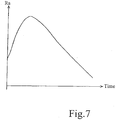
- the degree of measurement accuracy Ra is set to the smallest value, for example, 5 %, when Vrms is equal to Vtest. As shown in FIGURE 6 , judgment is made, in the revision computation processing in Step S28, as to whether the digital voltage detection signal Vrms is larger than the digital voltage detection signal ⁇ Vrms used in the previous revision computation processing (Step S30).
- the function f(Vrms/Vtest) is a function with an argument Vrms/Vtest, and its value increases when the value of Vrms/Vtest is increasing and decreases when the value of Vrms/Vtest is decreasing.
- ⁇ f(Vrms/Vtest) in the revised degree of measurement accuracy Ra is large, and, the revised degree of measurement accuracy Ra increases rapidly when the value of Vrms/Vtest is increasing, as shown in the first half portion of FIGURE 7 .
- Step S36 the computations of Z1open, Z2open, Z1inc and Z2inc are performed.
- Vrms is memorized as ⁇ Vrms (Step S38).
- Step S40 The impedance open-circuiting proportion initial value Rul is expressed in percent (%), and is a proportion of the upper limit impedance to the reference impedance (Z1ave, Z2ave).
- the upper limit impedance is the impedance at which the loudspeaker line 6 etc. can be considered to have been open-circuited, with the degree of measurement accuracy Ra being highest, or, in other words, with Ra having the smallest value.
- the impedance open-circuiting proportion initial value Rul is set by the worker at the time of initialization or re-initialization of the system, and is used for both Z1open and Z2open.
- Step S46 judgment is made as to whether Z1open is larger than an upper limit value Z1ul of the impedance at 20 KHz.
- the upper limit impedance value Z1ul is the upper limit value of the impedance expected to actually occur at 20 KHz when the loudspeaker line 6 etc. are open-circuited.
- the upper limit value Z1ul is manually set by the worker at the time of initialization or re-initialization of the system. Alternatively, Z1ave measured by DSP 10 at the time of initialization or re-initialization of the system is multiplied by a factor greater than 1, and the resultant product is set as the upper limit value Z1ul.
- Step S46 The reason why the judgment in Step S46 is done is that it is sometimes possible for the value of Z1open revised based on the degree of measurement accuracy Ra to be an impossible value.
- Z1open is used as Z1ul (Step S48) since it is impossible that Z1open is greater than Z1ul.
- Step S50 judgment is made as to whether the degree of measurement accuracy Ra is larger than an impedance increase proportion initial value Rll (Step S50).
- the impedance increase proportion initial value R11 is a value resulting from subtracting 1 (unity) from the reciprocal of the proportion of the reference impedance (Z1ave or Z2ave) to the impedance at which the impedance of the loudspeaker line 6 and the loudspeakers 8, when the degree of measurement accuracy Ra is highest, can be considered to have decreased.
- the impedance increase proportion initial value Rll is expressed in percent (%).
- Step S52 or S54 judgment is made as to whether Z1inc is smaller than a lower limit value Z1ll of the impedance Z1 at 20 KHz (Step S56).
- the impedance lower limit value Z1ll is the lower limit value at 20 KHz at which impedance decrease is expected to actually occur while no short-circuiting has occurred in the loudspeaker line 6 or the loudspeakers 8.
- the lower limit value Z1ll is manually set by the worker at the time of initialization or re-initialization of the system.
- Step S56 is executed since Z1inc revised in Step S54 sometimes takes a value which it cannot actually take. If the answer to the query made in Step S56 is YES, Z1inc is adopted as Z1ll (Step S58) since it is impossible for Z1inc to be smaller than Z1ll.
- Step S58 is finished or if the answer to the query made in Step S56 is NO, the processing for computing Z1open and Z2open is ended.
- Z2open and Z2inc are computed, using the impedance open-circuiting proportion initial value Rul, the impedance increase proportion initial value Rll, an upper limit value Z2ul of the impedance Z2 at 40 Hz, a lower limit value Z2ll of the impedance Z2 at 40 Hz, and the reference impedance Z2ave of the impedance Z2 at 40 Hz. Description of this processing is not made.
- Z2ave is 1,000 ⁇
- Z2ul is 2,000 ⁇
- Z211 is 500 ⁇
- Z2s1 is 20 ⁇
- Z1ave is 1,500 ⁇
- Zlul is 3,000 ⁇
- Z111 is 750 ⁇
- Z1sl is 30 ⁇
- Isl is 5 A
- Rul is 10 %
- Rll is 10 %
- Ra is 5 %
- Vtest is 5 V.
- the Ra of 5 % is the highest degree of accuracy.
- the measured impedance Z2 is 1,000 ⁇ and the measured impedance Z1 is 1,500 ⁇ , it is judged by the processing shown in FIGURE 4 that the loudspeaker line is in the proper state.
- the measured impedances Z2 and Z1 are 1,100 ⁇ and 1,500 ⁇ , respectively, it is judged by the processing shown in FIGURE 4 that open-circuiting is present.
- the measured impedances Z2 and Z1 are 1,100 ⁇ and 1,600 ⁇ , respectively, it is judged by the processing shown in FIGURE 4 that open-circuiting is present.
- the measured impedances Z2 and Z1 are 1,000 ⁇ and 1,400 ⁇ , respectively, it is judged by the processing shown in FIGURE 4 that increase has occurred. If the measured impedances Z2 and Z1 are 15 ⁇ and 10 ⁇ , respectively, it is judged by the processing shown in FIGURE 4 that short-circuiting has occurred.
- the measured impedance Z2 is 1,100 ⁇ and the measured impedance Z1 is 1,600 ⁇ , it is judged by the processing shown in FIGURE 4 that the loudspeaker line is in the normal state. If the measured impedances Z2 and Z1 are 2,300 ⁇ and 1,000 ⁇ , respectively, it is judged by the processing shown in FIGURE 4 that open-circuiting has occurred. If the measured impedances Z2 and Z1 are 1,400 ⁇ and 600 ⁇ , respectively, it is judged by the processing shown in FIGURE 4 that current has increased. If the measured impedances Z2 and Z1 are 15 ⁇ and 10 ⁇ , respectively, it is judged by the processing shown in FIGURE 4 that short-circuiting has occurred.
- Z2inc ⁇ Z211 and Z1inc ⁇ Z1II Z2inc ad Z1inc are changed to:
- the measured impedance Z2 is 1,000 ⁇ and the measured impedance Z1 is 1,600 ⁇ , it is judged by the processing shown in FIGURE 4 that the loudspeaker line is normal. If the measured impedances Z2 and Z1 are 2,500 ⁇ and 2,800 ⁇ , respectively, it is judged by the processing shown in FIGURE 4 that open-circuiting has occurred. If the measured impedances Z2 and Z1 are 400 ⁇ and 1,000 ⁇ , respectively, it is judged by the processing shown in FIGURE 4 that current has increased. If the measured impedances Z2 and Z1 are 15 ⁇ and 10 ⁇ , respectively, it is judged by the processing shown in FIGURE 4 that short-circuiting has occurred.
- the loudspeakers 8 generate heat due to a large value of Vrms, and it takes a long time for the temperature of the loudspeakers 8 to return to the temperature before they began to generate heat, erroneous judgment can be avoided since it takes a long time for Z1open, Z2open, Z1inc and Z2inc to return to their values before the heat generation occurred.
- the reference impedances Z1ave and Z2ave at 20 KHz and 40 Hz of the loudspeaker line 6 and the loudspeakers 8 are measured prior to the application of the audio signal, and judgment is made as to whether the reference impedance Z1ave is between predetermined allowable aging upper and lower limit values Z1UL and Z1LL for 20 KHz, or whether the reference impedance Z2ave is between predetermined allowable aging upper and lower limit values Z2UL and Z2LL for 40 Hz.
- the impedance of the loudspeakers 8 changes due to aging, and the reference impedances Z1ave and Z2ave also change as the impedance of the loudspeakers 8 changes. Judgment is made as to whether the reference impedance Z1ave is within an allowable range defined by the allowable upper limit Z1UL and the allowable lower limit Z1LL, which are the limits for 20 KHz indicating the necessity for replacement of the loudspeakers, or whether the reference impedance Z2ave is within an allowable range defined by the allowable upper limit Z2UL and the allowable lower limit Z2LL, which are the limits for 40 Hz indicating the necessity for replacement of the loudspeakers.
- an indication to recommend the replacement of loudspeakers is displayed on the notification device 28.
- Such judgment is made at a time when the public address system is not in use. For example, if the public address system is installed in a store, the judgment is made everyday at a given time within a time period after the store is closed and before the store is opened.
- Step S60 whether the time for examination comes or not is judged. If the answer to the query made in Step S60 is NO, the processing is ended. If the answer is YES, the DSP 10 provides the test signal (Step S62). Then, the reference impedances Z1ave and Z2ave are measured in the manner described with reference to FIGURE2 (Step S64). Judgment is made as to whether Z1ave is within the above-described allowable range defined by Z1UL and Z1LL and, at the same time, whether Z2ave is within the above-described allowable range defined by Z2UL and Z2LL (Step S66).
- Step S68 If the answer to the query made in Step S66 is NO, an error notification is displayed on the notification device 28 (Step S68) to recommend replacement of a loudspeaker. If the answer is YES, the measured Z1ave and Z2ave are stored (Step S70). The execution of the processing of Step S70 renews Z1ave and Z2ave for use in computing Z1open, Z2open, Z1inc and Z2inc in the processing shown in FIGURE 8 in later stages. This prevents erroneous judgment which would be caused by influence given by changes in impedance caused by aging.
- cross-spectrum analysis is used to determine the impedances Z1, Z2, Z1ave and Z2ave, but the impedances may be determined by using a band-pass filter having a narrow band capable of deriving the test signal to derive current and voltage of the test signal, and determine the impedances from the derived current and voltage, for example.
- the test signal has frequencies of 40 Hz and 20 KHz.
- the digital test signal from the DSP 10 is digital-to-analog converted and the resultant analog test signal is applied to the combiner 13.
- an analog test signal source is additionally used and a test signal from this analog test signal source may be applied to the combiner 13.
- the analog test signal is analog-to-digital converted and the resultant digital signal is applied to the DSP 10.
- open-circuiting and decrease in impedance of the loudspeaker line and loudspeakers are determined, but only one of them may be determined, instead.
Landscapes
- Health & Medical Sciences (AREA)
- General Health & Medical Sciences (AREA)
- Otolaryngology (AREA)
- Physics & Mathematics (AREA)
- Engineering & Computer Science (AREA)
- Acoustics & Sound (AREA)
- Signal Processing (AREA)
- Circuit For Audible Band Transducer (AREA)
Claims (1)
- Système de diffusion publique comprenant :une source de signal (2) d'un signal audio ;un amplificateur (4) afin d'amplifier ledit signal audio ;une ligne de haut-parleur (6) à travers laquelle est transmis un signal de sortie dudit amplificateur (4) ;une pluralité de haut-parleurs (8) connectés les uns aux autres en parallèle à ladite ligne de haut-parleur (6) ; etun système d'inspection de lignes de haut-parleurs pour examiner ladite ligne de haut-parleur, ledit système d'inspection de lignes de haut-parleurs comprenant :une source d'un signal d'essai contenant à la fois une première composante de fréquence proche de la plus basse fréquence d'une bande de fréquence audio humaine et une deuxième composante de fréquence proche de la fréquence la plus élevée de la bande de fréquence audio humaine ;un combineur (13) pour combiner ledit signal d'essai avec ledit signal audio et appliquer un signal résultant audit amplificateur (4) ;un moyen de détermination d'impédance pour dériver lesdites première et deuxième composantes de fréquence dudit signal d'essai contenu dans un signal de sortie dudit amplificateur (4) et la détermination, à partir de ladite première composante de fréquence dérivée, d'une première impédance (Z1) constatée depuis la sortie dudit amplificateur vers ladite pluralité de haut-parleurs à ladite première composante de fréquence, et la détermination, à partir de ladite deuxième composante de fréquence dérivée, d'une deuxième impédance (Z2) constatée depuis la sortie dudit amplificateur vers ladite pluralité de haut-parleurs au niveau de ladite deuxième composante de fréquence ; etun moyen de jugement pour la comparaison desdites première et deuxième impédances (Z1, Z2) avec les première et deuxième valeurs seuils prédéterminées de limite supérieure (Z1ouvert, Z2ouvert), respectivement, dans le but de détecter un circuit ouvert de ladite ligne de haut-parleur (6) et des haut-parleurs (8) au niveau desdites première et deuxième composantes de fréquence, et/ou la comparaison desdites première et deuxième impédances (Z1, Z2) avec les première et deuxième valeurs seuils prédéterminées de limite inférieure (Z1inc, Z2inc), respectivement, dans le but de détecter une diminution d'impédance de ladite ligne de haut-parleur (6) et des haut-parleurs (8) au niveau desdites première et deuxième composantes de fréquence pour ainsi juger si ladite première impédance (Z1) est supérieure à la première valeur seuil prédéterminée de limite supérieure (Z1ouvert) à ladite première composante de fréquence dans le but de détecter un circuit ouvert de ladite ligne de haut-parleur (6) et de la pluralité de haut-parleurs (8), ou si ladite deuxième impédance (Z2) est supérieure à la deuxième valeur seuil prédéterminée de limite supérieure (Z2ouvert) au niveau de ladite deuxième composante de fréquence dans le but de détecter un circuit ouvert de ladite ligne de haut-parleur (6) et de la pluralité de haut-parleurs (8), et la détermination du circuit ouvert de ladite ligne de haut-parleur (6) et la pluralité de haut-parleurs (8) si ledit jugement est affirmatif, et/ou pour juger si ladite première impédance (Z1) est inférieure à la première valeur seuil prédéterminée de limite inférieure (Z1inc) à ladite première composante de fréquence dans le but de détecter une diminution d'impédance de ladite ligne de haut-parleur (6) et de la pluralité de haut-parleurs (8), ou si ladite deuxième impédance (Z2) est inférieure à la deuxième valeur seuil prédéterminée de limite inférieure (Z2inc) au niveau de ladite deuxième composante de fréquence dans le but de détecter une diminution d'impédance de ladite ligne de haut-parleur (6) et de la pluralité de haut-parleurs (8), et la détermination que l'impédance de ladite ligne de haut-parleur (6) et de la pluralité de haut-parleurs (8) a diminué si ledit jugement est affirmatif ;
ledit système de diffusion publique comprenant en outre un moyen de filtrage pour alimenter, audit combineur (13), ledit signal audio à partir de ladite source de signal audio ayant ses composantes de fréquence identiques aux composantes de fréquence dudit signal d'essai atténué, seulement pendant que ladite source de signal d'essai émet ledit signal d'essai.
Priority Applications (1)
| Application Number | Priority Date | Filing Date | Title |
|---|---|---|---|
| EP13151672.6A EP2584792B2 (fr) | 2008-01-10 | 2008-01-10 | Dispositif d'inspection de ligne de haut-parleur |
Applications Claiming Priority (3)
| Application Number | Priority Date | Filing Date | Title |
|---|---|---|---|
| EP13151672.6A EP2584792B2 (fr) | 2008-01-10 | 2008-01-10 | Dispositif d'inspection de ligne de haut-parleur |
| PCT/JP2008/050198 WO2009087772A1 (fr) | 2008-01-10 | 2008-01-10 | Dispositif d'inspection de ligne de haut-parleur |
| EP08703062.3A EP2229006B2 (fr) | 2008-01-10 | 2008-01-10 | Dispositif d'inspection de ligne de haut-parleur |
Related Parent Applications (3)
| Application Number | Title | Priority Date | Filing Date |
|---|---|---|---|
| EP08703062.3 Division | 2008-01-10 | ||
| EP08703062.3A Division EP2229006B2 (fr) | 2008-01-10 | 2008-01-10 | Dispositif d'inspection de ligne de haut-parleur |
| EP08703062.3A Division-Into EP2229006B2 (fr) | 2008-01-10 | 2008-01-10 | Dispositif d'inspection de ligne de haut-parleur |
Publications (3)
| Publication Number | Publication Date |
|---|---|
| EP2584792A1 EP2584792A1 (fr) | 2013-04-24 |
| EP2584792B1 EP2584792B1 (fr) | 2014-04-16 |
| EP2584792B2 true EP2584792B2 (fr) | 2018-09-12 |
Family
ID=40852897
Family Applications (2)
| Application Number | Title | Priority Date | Filing Date |
|---|---|---|---|
| EP13151672.6A Active EP2584792B2 (fr) | 2008-01-10 | 2008-01-10 | Dispositif d'inspection de ligne de haut-parleur |
| EP08703062.3A Active EP2229006B2 (fr) | 2008-01-10 | 2008-01-10 | Dispositif d'inspection de ligne de haut-parleur |
Family Applications After (1)
| Application Number | Title | Priority Date | Filing Date |
|---|---|---|---|
| EP08703062.3A Active EP2229006B2 (fr) | 2008-01-10 | 2008-01-10 | Dispositif d'inspection de ligne de haut-parleur |
Country Status (3)
| Country | Link |
|---|---|
| EP (2) | EP2584792B2 (fr) |
| JP (1) | JP5123319B2 (fr) |
| WO (1) | WO2009087772A1 (fr) |
Families Citing this family (21)
| Publication number | Priority date | Publication date | Assignee | Title |
|---|---|---|---|---|
| EP3076545B1 (fr) | 2010-02-10 | 2020-12-16 | Goodix Technology (HK) Company Limited | Systeme et procede pour adapter un signal de haut-parleur |
| CN102420711B (zh) * | 2010-09-28 | 2014-04-30 | 鸿富锦精密工业(深圳)有限公司 | 网络通信设备及其侦测负载异常的方法 |
| PL2697076T3 (pl) | 2011-04-12 | 2020-07-27 | Välinge Innovation AB | Sposób wytwarzania warstwy |
| WO2013153484A1 (fr) * | 2012-04-10 | 2013-10-17 | Koninklijke Philips N.V. | Procédé et système de vérification d'un transducteur acoustique |
| JP5924116B2 (ja) * | 2012-05-17 | 2016-05-25 | ヤマハ株式会社 | 半導体集積回路及び信号増幅装置 |
| JP5772721B2 (ja) | 2012-05-24 | 2015-09-02 | アンデン株式会社 | 車両接近通報装置 |
| JP5997768B2 (ja) * | 2012-06-19 | 2016-09-28 | Toa株式会社 | スピーカー装置 |
| WO2014006893A1 (fr) * | 2012-07-04 | 2014-01-09 | パナソニック株式会社 | Dispositif d'alarme de proximité, système d'alarme de proximité, dispositif mobile et procédé permettant d'identifier une panne dans un système d'alarme de proximité |
| DE102012220137A1 (de) * | 2012-11-06 | 2014-05-08 | Robert Bosch Gmbh | Schaltungsanordnung und Verfahren zum Prüfen eines Mikrofons sowie System zum Betreiben eines Mikrofons mit einer derartigen Schaltungsanordnung |
| ES2545824T3 (es) * | 2012-11-20 | 2015-09-16 | Bombardier Transportation Gmbh | Reproducción de audio segura en interfaz hombre-máquina |
| US9119005B2 (en) * | 2013-04-11 | 2015-08-25 | Bose Corporation | Connection diagnostics for parallel speakers |
| CN105636828B (zh) | 2013-09-20 | 2018-09-25 | 松下知识产权经营株式会社 | 音响装置、音响系统、移动体装置、以及音响系统的故障诊断方法 |
| US9247345B2 (en) | 2014-04-14 | 2016-01-26 | Apple Inc. | Multi-channel audio system having a shared current sense element for estimating individual speaker impedances |
| US9332343B2 (en) | 2014-04-14 | 2016-05-03 | Apple Inc. | Multi-channel audio system having a shared current sense element for estimating individual speaker impedances using test signals |
| CN108419173A (zh) * | 2017-02-09 | 2018-08-17 | 钰太芯微电子科技(上海)有限公司 | 一种扬声器自适应调节系统及方法 |
| US11263895B2 (en) | 2017-04-05 | 2022-03-01 | Carrier Corporation | Audio riser active electrical supervision |
| EP3503591B1 (fr) | 2017-12-19 | 2021-02-03 | Honeywell International Inc. | Dispositif permettant de connecter et de déconnecter électriquement des portions d'une ligne électrique, système d'adresse publique, procédé de détection d'une défaillance dans une ligne électrique |
| JP7409122B2 (ja) * | 2020-01-31 | 2024-01-09 | ヤマハ株式会社 | 管理サーバー、音響管理方法、プログラム、音響クライアントおよび音響管理システム |
| KR102733893B1 (ko) * | 2021-12-08 | 2024-11-26 | 브이에스이앤티 주식회사 | 스피커 체크 유닛을 구비한 방송 시스템 |
| CN117880724B (zh) * | 2024-02-08 | 2024-07-19 | 上海傅里叶半导体有限公司 | 扬声器短路开路检测方法和扬声器故障检测系统 |
| EP4734556A1 (fr) * | 2024-10-25 | 2026-04-29 | Siemens Schweiz AG | Appareil et procédé d'inspection discrète d'un dispositif audio |
Family Cites Families (8)
| Publication number | Priority date | Publication date | Assignee | Title |
|---|---|---|---|---|
| JP2507711Y2 (ja) * | 1988-03-09 | 1996-08-21 | 日本無線株式会社 | スピ―カ回線監視回路 |
| JPH09218233A (ja) * | 1996-02-08 | 1997-08-19 | Harness Sogo Gijutsu Kenkyusho:Kk | 車両における負荷の断線検出装置 |
| JP2001036995A (ja) * | 1999-07-21 | 2001-02-09 | Toa Corp | スピーカ回線の異常検知装置 |
| JP2003274491A (ja) * | 2002-03-18 | 2003-09-26 | Mitsubishi Electric Corp | スピーカ断線検出装置 |
| JP2005241349A (ja) * | 2004-02-25 | 2005-09-08 | Matsushita Electric Ind Co Ltd | 制御装置 |
| KR100619055B1 (ko) * | 2004-11-16 | 2006-08-31 | 삼성전자주식회사 | 오디오/비디오 시스템의 스피커 모드 자동 설정 방법 및장치 |
| JP4493564B2 (ja) * | 2005-07-28 | 2010-06-30 | ティーオーエー株式会社 | スピーカライン検査装置及びスピーカライン検査装置用端末装置 |
| JP2007037024A (ja) * | 2005-07-29 | 2007-02-08 | Toa Corp | スピーカラインの検査装置 |
-
2008
- 2008-01-10 EP EP13151672.6A patent/EP2584792B2/fr active Active
- 2008-01-10 WO PCT/JP2008/050198 patent/WO2009087772A1/fr not_active Ceased
- 2008-01-10 EP EP08703062.3A patent/EP2229006B2/fr active Active
- 2008-01-10 JP JP2009548841A patent/JP5123319B2/ja active Active
Also Published As
| Publication number | Publication date |
|---|---|
| EP2584792A1 (fr) | 2013-04-24 |
| WO2009087772A1 (fr) | 2009-07-16 |
| EP2229006A1 (fr) | 2010-09-15 |
| EP2584792B1 (fr) | 2014-04-16 |
| EP2229006A4 (fr) | 2012-08-08 |
| EP2229006B1 (fr) | 2013-11-20 |
| EP2229006B2 (fr) | 2019-02-27 |
| JP5123319B2 (ja) | 2013-01-23 |
| JPWO2009087772A1 (ja) | 2011-05-26 |
Similar Documents
| Publication | Publication Date | Title |
|---|---|---|
| EP2584792B2 (fr) | Dispositif d'inspection de ligne de haut-parleur | |
| EP2465112B1 (fr) | Procédé, produit de programme d'ordinateur et système pour la détermination d'une qualité perçue d'un système audio | |
| US9025781B2 (en) | Sound quality evaluation apparatus and method thereof | |
| JP3015395B2 (ja) | オーディオ信号処理システムを点検する装置 | |
| KR101430321B1 (ko) | 오디오 시스템의 지각 품질을 결정하기 위한 방법 및 시스템 | |
| EP3631388A1 (fr) | Procédé et système de test de bruit, de vibration et de robustesse (nvh) d'un véhicule | |
| US20090099843A1 (en) | Method and system for the integral and diagnostic assessment of listening speech quality | |
| US8311232B2 (en) | Method for predicting loudspeaker preference | |
| CN101053016B (zh) | 构建第一频率补偿输入间距功率密度函数的方法和系统 | |
| US8041044B2 (en) | Method and apparatus for checking a measuring situation in the case of a hearing apparatus | |
| Ma et al. | Partial Loudness in Multitrack Mixing. | |
| Sottek et al. | Progress in roughness calculation | |
| Bauer et al. | A loudness-level monitor for broadcasting | |
| Sottek | Sound quality evaluation of noises with spectro-temporal patterns | |
| JP3569175B2 (ja) | 周波数分解能測定装置 | |
| JP3579866B2 (ja) | 周波数分解能測定装置 | |
| Völk | Loudness and noise rating: How may standardization bridge the gap between science and engineering? | |
| Jun et al. | Intelligent diagnostics for sound reproduction system by the use of PEAQ | |
| Genuit et al. | The importance of psychoacoustics in the USA-A personal view | |
| JPH07124137A (ja) | 聴覚機能検査装置 | |
| Torres | Rapid sound-quality assessment of background noise | |
| JP2001285443A (ja) | インターホン検査方法およびその装置 | |
| JP2024057456A (ja) | 震度推定装置、震度推定プログラム及び震度推定方法 | |
| Townsend et al. | Comparison of Total Harmonic Distortion Measures among Hearing Aid Test Systems | |
| Strasser et al. | Temporary hearing threshold shifts and restitution associated with exposures to industrial noise and classical music of 94 dB (A) for 1 hour and 91 dB (A) for 2 hours |
Legal Events
| Date | Code | Title | Description |
|---|---|---|---|
| PUAI | Public reference made under article 153(3) epc to a published international application that has entered the european phase |
Free format text: ORIGINAL CODE: 0009012 |
|
| AC | Divisional application: reference to earlier application |
Ref document number: 2229006 Country of ref document: EP Kind code of ref document: P |
|
| AK | Designated contracting states |
Kind code of ref document: A1 Designated state(s): AT BE BG CH CY CZ DE DK EE ES FI FR GB GR HR HU IE IS IT LI LT LU LV MC MT NL NO PL PT RO SE SI SK TR |
|
| GRAP | Despatch of communication of intention to grant a patent |
Free format text: ORIGINAL CODE: EPIDOSNIGR1 |
|
| 17P | Request for examination filed |
Effective date: 20131011 |
|
| RBV | Designated contracting states (corrected) |
Designated state(s): AT BE BG CH CY CZ DE DK EE ES FI FR GB GR HR HU IE IS IT LI LT LU LV MC MT NL NO PL PT RO SE SI SK TR |
|
| INTG | Intention to grant announced |
Effective date: 20131120 |
|
| GRAS | Grant fee paid |
Free format text: ORIGINAL CODE: EPIDOSNIGR3 |
|
| GRAA | (expected) grant |
Free format text: ORIGINAL CODE: 0009210 |
|
| AC | Divisional application: reference to earlier application |
Ref document number: 2229006 Country of ref document: EP Kind code of ref document: P |
|
| AK | Designated contracting states |
Kind code of ref document: B1 Designated state(s): AT BE BG CH CY CZ DE DK EE ES FI FR GB GR HR HU IE IS IT LI LT LU LV MC MT NL NO PL PT RO SE SI SK TR |
|
| REG | Reference to a national code |
Ref country code: GB Ref legal event code: FG4D |
|
| REG | Reference to a national code |
Ref country code: CH Ref legal event code: EP |
|
| REG | Reference to a national code |
Ref country code: AT Ref legal event code: REF Ref document number: 663147 Country of ref document: AT Kind code of ref document: T Effective date: 20140515 |
|
| REG | Reference to a national code |
Ref country code: IE Ref legal event code: FG4D |
|
| REG | Reference to a national code |
Ref country code: DE Ref legal event code: R096 Ref document number: 602008031635 Country of ref document: DE Effective date: 20140528 |
|
| REG | Reference to a national code |
Ref country code: AT Ref legal event code: MK05 Ref document number: 663147 Country of ref document: AT Kind code of ref document: T Effective date: 20140416 |
|
| REG | Reference to a national code |
Ref country code: NL Ref legal event code: VDEP Effective date: 20140416 |
|
| REG | Reference to a national code |
Ref country code: LT Ref legal event code: MG4D |
|
| PG25 | Lapsed in a contracting state [announced via postgrant information from national office to epo] |
Ref country code: BG Free format text: LAPSE BECAUSE OF FAILURE TO SUBMIT A TRANSLATION OF THE DESCRIPTION OR TO PAY THE FEE WITHIN THE PRESCRIBED TIME-LIMIT Effective date: 20140716 Ref country code: FI Free format text: LAPSE BECAUSE OF FAILURE TO SUBMIT A TRANSLATION OF THE DESCRIPTION OR TO PAY THE FEE WITHIN THE PRESCRIBED TIME-LIMIT Effective date: 20140416 Ref country code: GR Free format text: LAPSE BECAUSE OF FAILURE TO SUBMIT A TRANSLATION OF THE DESCRIPTION OR TO PAY THE FEE WITHIN THE PRESCRIBED TIME-LIMIT Effective date: 20140717 Ref country code: CY Free format text: LAPSE BECAUSE OF FAILURE TO SUBMIT A TRANSLATION OF THE DESCRIPTION OR TO PAY THE FEE WITHIN THE PRESCRIBED TIME-LIMIT Effective date: 20140416 Ref country code: NO Free format text: LAPSE BECAUSE OF FAILURE TO SUBMIT A TRANSLATION OF THE DESCRIPTION OR TO PAY THE FEE WITHIN THE PRESCRIBED TIME-LIMIT Effective date: 20140716 Ref country code: IS Free format text: LAPSE BECAUSE OF FAILURE TO SUBMIT A TRANSLATION OF THE DESCRIPTION OR TO PAY THE FEE WITHIN THE PRESCRIBED TIME-LIMIT Effective date: 20140816 Ref country code: LT Free format text: LAPSE BECAUSE OF FAILURE TO SUBMIT A TRANSLATION OF THE DESCRIPTION OR TO PAY THE FEE WITHIN THE PRESCRIBED TIME-LIMIT Effective date: 20140416 Ref country code: NL Free format text: LAPSE BECAUSE OF FAILURE TO SUBMIT A TRANSLATION OF THE DESCRIPTION OR TO PAY THE FEE WITHIN THE PRESCRIBED TIME-LIMIT Effective date: 20140416 |
|
| PG25 | Lapsed in a contracting state [announced via postgrant information from national office to epo] |
Ref country code: HR Free format text: LAPSE BECAUSE OF FAILURE TO SUBMIT A TRANSLATION OF THE DESCRIPTION OR TO PAY THE FEE WITHIN THE PRESCRIBED TIME-LIMIT Effective date: 20140416 Ref country code: PL Free format text: LAPSE BECAUSE OF FAILURE TO SUBMIT A TRANSLATION OF THE DESCRIPTION OR TO PAY THE FEE WITHIN THE PRESCRIBED TIME-LIMIT Effective date: 20140416 Ref country code: ES Free format text: LAPSE BECAUSE OF FAILURE TO SUBMIT A TRANSLATION OF THE DESCRIPTION OR TO PAY THE FEE WITHIN THE PRESCRIBED TIME-LIMIT Effective date: 20140416 Ref country code: SE Free format text: LAPSE BECAUSE OF FAILURE TO SUBMIT A TRANSLATION OF THE DESCRIPTION OR TO PAY THE FEE WITHIN THE PRESCRIBED TIME-LIMIT Effective date: 20140416 Ref country code: LV Free format text: LAPSE BECAUSE OF FAILURE TO SUBMIT A TRANSLATION OF THE DESCRIPTION OR TO PAY THE FEE WITHIN THE PRESCRIBED TIME-LIMIT Effective date: 20140416 Ref country code: AT Free format text: LAPSE BECAUSE OF FAILURE TO SUBMIT A TRANSLATION OF THE DESCRIPTION OR TO PAY THE FEE WITHIN THE PRESCRIBED TIME-LIMIT Effective date: 20140416 |
|
| PG25 | Lapsed in a contracting state [announced via postgrant information from national office to epo] |
Ref country code: PT Free format text: LAPSE BECAUSE OF FAILURE TO SUBMIT A TRANSLATION OF THE DESCRIPTION OR TO PAY THE FEE WITHIN THE PRESCRIBED TIME-LIMIT Effective date: 20140818 |
|
| REG | Reference to a national code |
Ref country code: DE Ref legal event code: R026 Ref document number: 602008031635 Country of ref document: DE |
|
| PLBI | Opposition filed |
Free format text: ORIGINAL CODE: 0009260 |
|
| PG25 | Lapsed in a contracting state [announced via postgrant information from national office to epo] |
Ref country code: DK Free format text: LAPSE BECAUSE OF FAILURE TO SUBMIT A TRANSLATION OF THE DESCRIPTION OR TO PAY THE FEE WITHIN THE PRESCRIBED TIME-LIMIT Effective date: 20140416 Ref country code: EE Free format text: LAPSE BECAUSE OF FAILURE TO SUBMIT A TRANSLATION OF THE DESCRIPTION OR TO PAY THE FEE WITHIN THE PRESCRIBED TIME-LIMIT Effective date: 20140416 Ref country code: BE Free format text: LAPSE BECAUSE OF FAILURE TO SUBMIT A TRANSLATION OF THE DESCRIPTION OR TO PAY THE FEE WITHIN THE PRESCRIBED TIME-LIMIT Effective date: 20140416 Ref country code: SK Free format text: LAPSE BECAUSE OF FAILURE TO SUBMIT A TRANSLATION OF THE DESCRIPTION OR TO PAY THE FEE WITHIN THE PRESCRIBED TIME-LIMIT Effective date: 20140416 Ref country code: CZ Free format text: LAPSE BECAUSE OF FAILURE TO SUBMIT A TRANSLATION OF THE DESCRIPTION OR TO PAY THE FEE WITHIN THE PRESCRIBED TIME-LIMIT Effective date: 20140416 |
|
| 26 | Opposition filed |
Opponent name: NOVAR GMBH Effective date: 20150115 |
|
| PLAX | Notice of opposition and request to file observation + time limit sent |
Free format text: ORIGINAL CODE: EPIDOSNOBS2 |
|
| REG | Reference to a national code |
Ref country code: DE Ref legal event code: R082 Ref document number: 602008031635 Country of ref document: DE Representative=s name: PATENTANWAELTE LIPPERT, STACHOW & PARTNER, DE Ref country code: DE Ref legal event code: R082 Ref document number: 602008031635 Country of ref document: DE Representative=s name: LIPPERT STACHOW PATENTANWAELTE RECHTSANWAELTE , DE |
|
| REG | Reference to a national code |
Ref country code: DE Ref legal event code: R026 Ref document number: 602008031635 Country of ref document: DE Effective date: 20150115 |
|
| PG25 | Lapsed in a contracting state [announced via postgrant information from national office to epo] |
Ref country code: IT Free format text: LAPSE BECAUSE OF FAILURE TO SUBMIT A TRANSLATION OF THE DESCRIPTION OR TO PAY THE FEE WITHIN THE PRESCRIBED TIME-LIMIT Effective date: 20140416 |
|
| PLAF | Information modified related to communication of a notice of opposition and request to file observations + time limit |
Free format text: ORIGINAL CODE: EPIDOSCOBS2 |
|
| PG25 | Lapsed in a contracting state [announced via postgrant information from national office to epo] |
Ref country code: SI Free format text: LAPSE BECAUSE OF FAILURE TO SUBMIT A TRANSLATION OF THE DESCRIPTION OR TO PAY THE FEE WITHIN THE PRESCRIBED TIME-LIMIT Effective date: 20140416 |
|
| REG | Reference to a national code |
Ref country code: CH Ref legal event code: PL |
|
| PG25 | Lapsed in a contracting state [announced via postgrant information from national office to epo] |
Ref country code: LU Free format text: LAPSE BECAUSE OF FAILURE TO SUBMIT A TRANSLATION OF THE DESCRIPTION OR TO PAY THE FEE WITHIN THE PRESCRIBED TIME-LIMIT Effective date: 20150110 |
|
| PG25 | Lapsed in a contracting state [announced via postgrant information from national office to epo] |
Ref country code: MC Free format text: LAPSE BECAUSE OF FAILURE TO SUBMIT A TRANSLATION OF THE DESCRIPTION OR TO PAY THE FEE WITHIN THE PRESCRIBED TIME-LIMIT Effective date: 20140416 |
|
| PLBB | Reply of patent proprietor to notice(s) of opposition received |
Free format text: ORIGINAL CODE: EPIDOSNOBS3 |
|
| PG25 | Lapsed in a contracting state [announced via postgrant information from national office to epo] |
Ref country code: CH Free format text: LAPSE BECAUSE OF NON-PAYMENT OF DUE FEES Effective date: 20150131 Ref country code: LI Free format text: LAPSE BECAUSE OF NON-PAYMENT OF DUE FEES Effective date: 20150131 |
|
| REG | Reference to a national code |
Ref country code: IE Ref legal event code: MM4A |
|
| PLAY | Examination report in opposition despatched + time limit |
Free format text: ORIGINAL CODE: EPIDOSNORE2 |
|
| REG | Reference to a national code |
Ref country code: FR Ref legal event code: PLFP Year of fee payment: 9 |
|
| PG25 | Lapsed in a contracting state [announced via postgrant information from national office to epo] |
Ref country code: IE Free format text: LAPSE BECAUSE OF NON-PAYMENT OF DUE FEES Effective date: 20150110 |
|
| PLAH | Information related to despatch of examination report in opposition + time limit modified |
Free format text: ORIGINAL CODE: EPIDOSCORE2 |
|
| PLBC | Reply to examination report in opposition received |
Free format text: ORIGINAL CODE: EPIDOSNORE3 |
|
| REG | Reference to a national code |
Ref country code: FR Ref legal event code: PLFP Year of fee payment: 10 |
|
| PG25 | Lapsed in a contracting state [announced via postgrant information from national office to epo] |
Ref country code: MT Free format text: LAPSE BECAUSE OF FAILURE TO SUBMIT A TRANSLATION OF THE DESCRIPTION OR TO PAY THE FEE WITHIN THE PRESCRIBED TIME-LIMIT Effective date: 20140416 |
|
| PG25 | Lapsed in a contracting state [announced via postgrant information from national office to epo] |
Ref country code: RO Free format text: LAPSE BECAUSE OF FAILURE TO SUBMIT A TRANSLATION OF THE DESCRIPTION OR TO PAY THE FEE WITHIN THE PRESCRIBED TIME-LIMIT Effective date: 20140416 Ref country code: HU Free format text: LAPSE BECAUSE OF FAILURE TO SUBMIT A TRANSLATION OF THE DESCRIPTION OR TO PAY THE FEE WITHIN THE PRESCRIBED TIME-LIMIT; INVALID AB INITIO Effective date: 20080110 |
|
| PG25 | Lapsed in a contracting state [announced via postgrant information from national office to epo] |
Ref country code: TR Free format text: LAPSE BECAUSE OF FAILURE TO SUBMIT A TRANSLATION OF THE DESCRIPTION OR TO PAY THE FEE WITHIN THE PRESCRIBED TIME-LIMIT Effective date: 20140416 |
|
| REG | Reference to a national code |
Ref country code: FR Ref legal event code: PLFP Year of fee payment: 11 |
|
| PUAH | Patent maintained in amended form |
Free format text: ORIGINAL CODE: 0009272 |
|
| STAA | Information on the status of an ep patent application or granted ep patent |
Free format text: STATUS: PATENT MAINTAINED AS AMENDED |
|
| 27A | Patent maintained in amended form |
Effective date: 20180912 |
|
| AK | Designated contracting states |
Kind code of ref document: B2 Designated state(s): AT BE BG CH CY CZ DE DK EE ES FI FR GB GR HR HU IE IS IT LI LT LU LV MC MT NL NO PL PT RO SE SI SK TR |
|
| REG | Reference to a national code |
Ref country code: DE Ref legal event code: R102 Ref document number: 602008031635 Country of ref document: DE |
|
| PGFP | Annual fee paid to national office [announced via postgrant information from national office to epo] |
Ref country code: GB Payment date: 20251218 Year of fee payment: 19 |
|
| PGFP | Annual fee paid to national office [announced via postgrant information from national office to epo] |
Ref country code: FR Payment date: 20251222 Year of fee payment: 19 |
|
| PGFP | Annual fee paid to national office [announced via postgrant information from national office to epo] |
Ref country code: DE Payment date: 20251224 Year of fee payment: 19 |