EP2583931A1 - Vorrichtung und Verfahren zum Befüllen von Behältern - Google Patents
Vorrichtung und Verfahren zum Befüllen von Behältern Download PDFInfo
- Publication number
- EP2583931A1 EP2583931A1 EP12175301.6A EP12175301A EP2583931A1 EP 2583931 A1 EP2583931 A1 EP 2583931A1 EP 12175301 A EP12175301 A EP 12175301A EP 2583931 A1 EP2583931 A1 EP 2583931A1
- Authority
- EP
- European Patent Office
- Prior art keywords
- filling
- containers
- carousel
- stations
- container
- Prior art date
- Legal status (The legal status is an assumption and is not a legal conclusion. Google has not performed a legal analysis and makes no representation as to the accuracy of the status listed.)
- Granted
Links
- 238000000034 method Methods 0.000 title claims abstract description 18
- 238000005303 weighing Methods 0.000 claims abstract description 46
- 239000000945 filler Substances 0.000 claims abstract description 41
- 238000007599 discharging Methods 0.000 abstract 1
- 230000009969 flowable effect Effects 0.000 description 14
- 235000013361 beverage Nutrition 0.000 description 3
- 238000005259 measurement Methods 0.000 description 3
- 239000006072 paste Substances 0.000 description 3
- 239000000126 substance Substances 0.000 description 3
- 238000010586 diagram Methods 0.000 description 2
- 238000005429 filling process Methods 0.000 description 2
- 238000012546 transfer Methods 0.000 description 2
- 238000005452 bending Methods 0.000 description 1
- 230000005540 biological transmission Effects 0.000 description 1
- 239000000969 carrier Substances 0.000 description 1
- 238000013461 design Methods 0.000 description 1
- 239000003814 drug Substances 0.000 description 1
- 229940079593 drug Drugs 0.000 description 1
- 239000011521 glass Substances 0.000 description 1
- 239000007788 liquid Substances 0.000 description 1
- 239000000825 pharmaceutical preparation Substances 0.000 description 1
- 229940127557 pharmaceutical product Drugs 0.000 description 1
- 238000012545 processing Methods 0.000 description 1
Images


Classifications
-
- G—PHYSICS
- G01—MEASURING; TESTING
- G01G—WEIGHING
- G01G15/00—Arrangements for check-weighing of materials dispensed into removable containers
-
- B—PERFORMING OPERATIONS; TRANSPORTING
- B67—OPENING, CLOSING OR CLEANING BOTTLES, JARS OR SIMILAR CONTAINERS; LIQUID HANDLING
- B67C—CLEANING, FILLING WITH LIQUIDS OR SEMILIQUIDS, OR EMPTYING, OF BOTTLES, JARS, CANS, CASKS, BARRELS, OR SIMILAR CONTAINERS, NOT OTHERWISE PROVIDED FOR; FUNNELS
- B67C3/00—Bottling liquids or semiliquids; Filling jars or cans with liquids or semiliquids using bottling or like apparatus; Filling casks or barrels with liquids or semiliquids
- B67C3/02—Bottling liquids or semiliquids; Filling jars or cans with liquids or semiliquids using bottling or like apparatus
- B67C3/20—Bottling liquids or semiliquids; Filling jars or cans with liquids or semiliquids using bottling or like apparatus with provision for metering the liquids to be introduced, e.g. when adding syrups
- B67C3/202—Bottling liquids or semiliquids; Filling jars or cans with liquids or semiliquids using bottling or like apparatus with provision for metering the liquids to be introduced, e.g. when adding syrups by weighing
-
- G—PHYSICS
- G01—MEASURING; TESTING
- G01G—WEIGHING
- G01G17/00—Apparatus for or methods of weighing material of special form or property
- G01G17/04—Apparatus for or methods of weighing material of special form or property for weighing fluids, e.g. gases, pastes
Definitions
- the invention relates to a device for filling containers with the features of the preamble of claim 1.
- Devices for filling containers are usually used to fill a predetermined amount of a flowable medium in containers.
- the flowable medium includes drinks, liquid medicines, chemicals or pastes.
- Such devices have a filler with rotating container stations, which transport the containers at a constant container speed and at the same time fill and / or weigh. About an inlet of the device while empty containers are supplied and filled containers are discharged through a drain.
- each container station usually also works as a measuring station.
- the empty weight of the container is determined with a weighing element assigned to the container station.
- the first measurement time results essentially after a settling time of the weighing element, since this initially resonates through the applied mass of the empty container.
- the container station operates as a filling station and the container is filled by a time-controlled metering device with the flowable medium.
- a valve is opened in the metering device and released the flow of the flowable medium for a predetermined filling time.
- the container station again works as a measuring station during a further measuring time to determine the final weight of the container.
- the capacity of the flowable medium is calculated.
- the further measuring time results essentially from a renewed settling time of the filled container on the weighing element. If the measured filling quantity of the container deviates from the set filling quantity, the timing for subsequent containers is corrected accordingly.
- the object of the invention is to provide a device and a method for filling containers with a more compact filler and to use the metering devices and the weighing elements more efficiently and to determine the exact amount of filling.
- the invention provides a device for filling containers with the features of the preamble of claim 1 with the features of the characterizing part, according to which the filler is associated with a carousel with a plurality of measuring stations for weighing the container, wherein a measuring section of the carousel for determining the Empty weight of the container in the inlet and a measuring section of the same carousel for determining the final weight of the container is formed in the process.
- the device according to the invention has a carousel with measuring stations for weighing the containers, which is associated with the filler such that a measuring section of the carousel for determining the empty weight of the container in the inlet and a measuring section of the same carousel for determining the final weight of the container is formed in the process , the container stations operating in the state of the art as measuring stations are no longer needed in the filler.
- the filler can thus be made more compact.
- the container stations of the filler in the device according to the invention can be designed as pure filling stations and no longer have weighing elements. While the filler elements are used in the inventive device during the entire filling process, both the empty and the full container are weighed in the associated weighing carousel at the same time.
- the weighing carousel is used not only for weighing the final weight of the containers but also for weighing their empty weight, without requiring more design, synchronizing the pen and carousel and the control. As a result, the filling amount of the container can be determined more accurately.
- a device according to the invention is generally broadly usable. It can be used, for example, for filling a variety of flowable media such as drinks, pastes, chemical, biological and / or pharmaceutical products.
- the device can be arranged in a beverage processing plant.
- the containers may in particular be beverage containers, in particular including plastic bottles, glass bottles and / or cans.
- the device for filling containers may be designed to fill a continuous stream of containers each with a predetermined filling amount and to detect them by weighing.
- the carousel can be designed so that the empty weight of all containers in the inlet and the final weight of all containers is weighed in the process.
- the carousel may be designed such that the measuring stations rotate about a common axis on a circular path and in particular the measuring section for determining the empty weight in the inlet is formed by a first circular sector and the measuring section for determining the final weight in the course of a second circular sector is formed.
- the two measuring sections may be formed overlapping on the circular path of the measuring stations, wherein in particular the measuring stations are assigned to the two measuring sections alternately.
- the determination of the empty weight may mean that the container is already filled with at least one component from a previous process step and this is assigned to the empty weight of the container.
- the carousel may be designed such that the empty containers can be fed to the carousel via a feed and the filled containers can be discharged via an outlet.
- the carousel may be designed in such a way that the containers in the measuring stations are continuously transported further as they pass through the two measuring sections.
- the measuring stations can be designed with carriers, which cause the transport of the container.
- the carousel may be designed such that the containers are transported in the carousel at the same container speed as in the filler. This ensures a better synchronization of the pen and the carousel.
- the carousel and the filler can be designed such that the containers are transported in a fixed grid, similar to the links of a chain through both systems. Thereby, a continuous container flow through the device can be ensured.
- At least one transport star can be arranged between the filler and the carousel.
- two transport stars can be arranged between the filler and the carousel, which transfer the containers in each case in the inlet and in the process. This helps to transport the containers.
- the carousel may in particular be provided to determine the capacity of the discharged containers.
- the carousel be designed such that from the difference between the final weight and the empty weight of each container its capacity is calculated.
- the filling amount may mean the filling weight and / or the filling volume.
- Each measuring station may comprise at least one weighing element.
- the weighing elements can be rotatably arranged together with the measuring stations about the axis of the carousel.
- the weighing element may include an electronic force sensor, which is particularly suitable for outputting a value for the weight of the container as an electrical signal.
- the container can stand up on at least one weighing element on the bottom side.
- the at least one weighing element may be arranged in the measuring station on a platform which rotates about the axis of rotation of the carousel.
- the already mentioned driver can be designed so that it laterally stabilizes the container in the measuring station during weighing.
- the weighing element may have a connection to a container neck.
- the weighing element may comprise a lever-like arm, wherein in particular the lever-like arm exerts a force on a force sensor during weighing.
- the force sensor may comprise a strain gauge, a piezosensor or a sensor based on the dynamic force compensation.
- the container neck can be connected via a clamping element with the lever-like arm, wherein in particular the clamping element receives the weight of the container and stabilizes it laterally.
- such a weighing element can weigh the container by a receptacle on the neck, wherein in particular the container floats on the bottom side.
- Each filling station may comprise at least one time-controlled dosing unit.
- At least one time-controlled dosing unit can mean that at least one flowable medium, each with a time-controlled dosing unit, can be filled in the filling station.
- the at least one time-controlled dosing unit can comprise a valve which can be controlled via an electronic or pneumatic signal. This makes the dosing unit particularly simple and thus cost-effective.
- the device may comprise at least one electronic control unit.
- the electronic control unit may be configured to receive measurement signals from the measurement stations that correspond to the tare weights, final weights, and / or fill levels of the containers.
- the electronic control unit can be designed so that it receives signals from at least one sensor, which may be in particular a rotary encoder, Hall sensor and / or container counter.
- the electronic control unit may be provided to output signals, in particular to control at least one electric motor, which may be in particular a servo and / or a stepper motor.
- the at least an electronic control unit adapted to send signals to control the quantities in the filling stations, which in particular may be arranged to control the timed dosing units.
- the at least one electronic control unit may be provided to associate the curb weight and the final weight of a particular container.
- the at least one electronic control unit can be provided to allocate the filling amounts of the containers to the filling stations and thus generate signals for correcting the filling times.
- the electronic control unit may be configured to detect the absolute angular positions of the filler and the carousel, in particular to establish a correlation between the filler and the carousel. The correlation may include with which filling station in the filler a certain container has been filled, which is weighed at an earlier time in the inlet and at a later time in the process in the carousel in a measuring station.
- the filler and the carousel may be connected via a bus system which is intended to exchange data.
- the filler and the carousel can be designed in each case with at least one control unit, which are connected to each other via the bus system. As a result, the filler and the carousel with the measuring stations are more flexible.
- the invention further provides a method for filling containers according to claim 12, according to which the containers are fed to a carousel with measuring stations, where their empty weights are determined in a measuring section associated with the feed and then transferred from the carousel to a filler, where it is filled and then in turn passed to the same carousel to determine their final weights in a flow associated with the measuring section.
- the measuring stations can be used efficiently in the carousel.
- the method can be carried out in particular with a device described above.
- the method may include providing a device as described above.
- the containers can be assigned to the filling stations during filling and, in particular, fill-in values from the empty weights and the final weights for the containers can be calculated and assigned to the respective filling stations in the carousel.
- filling quantity average values can be formed from the filling quantity values in order to thereby correct the filling times of the filling stations.
- the filling mean value may mean that the filling amount values are averaged at a specific time, which were filled in the filler within a certain period of time before this time.
- FIG. 1 shows an embodiment of an inventive device 1 for filling containers 11 in a plan view.
- a carousel 4 which has a plurality of measuring stations 41, which are arranged regularly over the circumference of the carousel.
- the carousel 4 is designed to be rotatable about an axis A and is driven, for example via an electric motor and a transmission (not shown), so that it is at a constant angular velocity rotates. As a result, the measuring stations 41 also rotate at a constant speed about the axis A.
- the measuring stations 41 are designed with drivers 43, which further transport the containers 11 in the carousel 4 and stabilize them during weighing.
- the measuring stations 41 are designed with weighing elements 42 so that the containers in the measuring stations can be weighed while the carousel 4 is rotating and the containers 11 are continuously transported.
- a part of the measuring stations 41 of the carousel 4 forms the measuring section M1 for determining the empty weight of the container 11 in the inlet 12 of the device.
- the carousel is designed so that it rotates about the axis A and continuously forms another part of the total amount of all measuring stations 41, the measuring section M1.
- another part of the total quantity of all measuring stations 41 of the carousel 4 continually forms the measuring section M2 for determining the final weight of the containers 11 in the outlet 13 of the device.
- the carousel 4 is associated with a filler 2 of the device, which is intended to fill the container 11 with a predetermined amount of a flowable medium.
- the flowable medium may be a beverage, a paste, a chemical, pharmaceutical and / or biological product.
- a tank 23 is arranged, which includes a supply of the flowable medium.
- the filler 2 can be designed such that it is continuously supplied via a pipe system, the flowable medium.
- the timed metering devices 22 in the filling stations 21 are connected to the tank 23, and are intended to fill a predetermined amount of the flowable medium in each container 11. With the holders 24 while the container during transport in the filling stations 21 are stabilized.
- the filler 2 rotates at a constant angular velocity about the axis B and is designed with filling stations 21 so that they rotate in a circular path about the axis B.
- the angular velocities of the filler 2 and the carousel 4 are adjusted to one another in such a way that the containers 11 move therein at the same container speed.
- two transport stars 6A, 6B are arranged, which transfer the containers.
- the angular velocities of the transport stars 6A, 6B are adjusted so that the containers in the transport stars move at the same container speed as in the filler 2 and in the carousel 4.
- the device 1 is designed so that empty containers 11 are fed via a feed 14 to the measuring stations 41 of the carousel 4.
- each container 11 on a weighing element 42 first a settling time and is then weighed in the further course of the measuring section M1 to determine the curb weight and output as an electrical signal.
- this electrical signal may be received by an electronic controller (not shown).
- the empty container 11 moves at a constant container speed along the measuring path M1 and is output to the end of the measuring path M1 to a transport star 6A.
- the container 11 is transferred to the filler and filled there by means of a time-controlled metering device 22 in a specific filling station 21 with the flowable medium.
- the container is continuously transported until it is handed over to the star conveyor 6B after completion of the filling.
- the container 11 is transported in the outlet 13 to a measuring station 41 in the carousel 4.
- the final weight of the container 11 is determined with another weighing element 42 after a further settling time and in turn output as an electrical signal.
- the empty weight and the final weight of the container 11 can be determined in different measuring stations 41 of the carousel 4.
- the filled container 11 moves at a constant container speed along the measuring section M2 and is discharged at the end of the discharge 15.
- FIG. 2A is a carousel 4 with measuring stations 41 of in FIG. 1 illustrated device shown in a plan view. Also visible is a platform 44 on which the measuring stations 41 are arranged and which each have weighing elements 42 and drivers 43. In some of the measuring stations 41, containers are arranged in the region of the measuring sections M1 and M2.
- FIG. 2B shows an example of a measuring station 41 in a sectional view along the section line AA in FIG. 2A , It is illustrated that on the platform 44, the weighing element 42 is located on a container 11 on the bottom side. With the weighing element 42, it is possible in this arrangement to measure the weight of the container 41.
- the container 11 may be both empty and filled in the illustrated arrangement.
- the container 11 is laterally stabilized by the driver 43 and supported during transport in the carousel 4.
- the arrangement shown may be part of the measuring section M1 or M2 in FIG. 2A form.
- FIG. 3 shows a further example of a measuring station 41 in a side view.
- the container 11 hangs in the measuring station 41 via a connection on the container neck 11B.
- the container neck 11 B has a collar 11A.
- the container neck 11B is thus received and transported in a clamp member 47 during weighing.
- the clamping element 47 is designed so that it has a detachable connection to the container 11.
- the clamping element 47 is connected to the weighing element 42, which is designed as a lever-like arm 45 and has a force sensor 46.
- the lever-like arm 45 is fixedly connected at the other end to the shaft 48, which is rotated by a drive element 49 about the axis A.
- a rotary encoder 50 is designed so that it outputs the absolute angular position of the shaft 48 and thus the measuring stations 41 as a signal.
- the drive element 49 is mounted with a flange in a fixed base plate 51. It goes without saying that the shaft 48 is connected to a plurality of measuring stations 41 designed in this way.
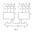
- FIG. 4 shows an example of electronic controls 2C, 4C with a bus system 8 as a block diagram.
- a first electronic control 2C for example, the filler 2 in FIG. 1 assigned. This is connected to a plurality of timed metering devices 22 via electrical lines 82 and sends these signals to valves in the metering devices 22 to open or close.
- the filling times of the filling stations 21 in the FIG. 1 to be controlled.
- the first electronic controller 2C an electrical line to a rotary encoder 25, which sends the absolute angular position of the filling stations 21 as an electrical signal to the electronic control 2C.
- the angular position of a particular filling station 21 in the electronic controller 2C can be calculated.
- a second electronic control 4C which, for example, the carousel 4 with the measuring stations 41 in FIG. 1 assigned.
- This has a plurality of electrical connections 84 to weighing elements 42 and receives from these signals corresponding to the tare weights and the final weights of the containers 11.
- the second electronic controller 4C receives a signal from another rotary encoder 50 in the carousel 4, from which the angular positions of the measuring stations 41 in FIG. 1 let calculate.
- Both electronic controllers 2C, 4C are interconnected via a bus system 8, with which these data and / or signals exchange.
- the empty weight of a container 11 can first be stored in a memory. The final weight of the same container 11 can be assigned after filling this stored empty weight.
- the second electronic controller 4C then calculates the filling amount value of the container 11 and sends it via the bus system 8 to the first controller 2C, which then allocates the filling amount value to a specific filling station 21.
- the filling amount values of a plurality of containers 11 for a plurality of filling stations 21 are then stored correspondingly in the memory of the first electronic controller 2C. From the filling quantity values of a multiplicity of containers 11, filling mean values for each individual filling station 21 are then calculated and compared with the predetermined filling quantity. This then calculates a new, corrected filling time for each individual filling station 21 in order to fill the following containers 11 with the predetermined filling quantity.
Landscapes
- Physics & Mathematics (AREA)
- General Physics & Mathematics (AREA)
- Basic Packing Technique (AREA)
- Filling Of Jars Or Cans And Processes For Cleaning And Sealing Jars (AREA)
Abstract
Description
- Die Erfindung betrifft eine Vorrichtung zum Befüllen von Behältern mit den Merkmalen des Oberbegriffs von Patentanspruch 1.
- Vorrichtungen zum Befüllen von Behältern dienen üblicherweise dazu, eine vorherbestimmte Füllmenge eines fließfähigen Mediums in Behälter einzufüllen. Das fließfähige Medium umfasst dabei Getränke, flüssige Medikamente, chemische Erzeugnisse oder Pasten. Derartige Vorrichtungen weisen einen Füller mit umlaufenden Behälterstationen auf, welche die Behälter mit einer konstanten Behältergeschwindigkeit weitertransportieren und gleichzeitig befüllen und/oder wiegen. Über einen Zulauf werden der Vorrichtung dabei leere Behälter zugeführt und befüllte Behälter werden über einen Ablauf abgeführt.
- Befüllvorrichtungen dieser Art gibt es in den verschiedensten Ausführungsformen. Bei einer Gattung arbeitet jede Behälterstation üblicherweise auch als Messstation. Dabei wird nach dem Zulauf das Leergewicht des Behälters mit einem der Behälterstation zugeordneten Wiegeelement ermittelt. Die erste Messzeit ergibt sich dabei im Wesentlichen nach einer Beruhigungszeit des Wiegeelements, da dieses zunächst durch die aufgebrachte Masse des leeren Behälters nachschwingt. Anschließend arbeitet die Behälterstation als Füllstation und der Behälter wird durch eine zeitgesteuerte Dosiereinrichtung mit dem fließfähigen Medium befüllt. Dabei wird ein Ventil in der Dosiereinrichtung geöffnet und der Fluss des fließfähigen Mediums für eine vorherbestimmte Füllzeit freigegeben. Nach der Befüllung arbeitet die Behälterstation wiederum während einer weiteren Messzeit als Messstation zur Bestimmung des Endgewichts des Behälters. Aus der Differenz zwischen dem Leergewicht und dem Endgewicht wird so die Füllmenge des fließfähigen Mediums berechnet. Die weitere Messzeit ergibt sich wiederum im Wesentlichen aus einer erneuten Beruhigungszeit des befüllten Behälters auf dem Wiegeelement. Falls die gemessene Füllmenge des Behälters von der eingestellten Füllmenge abweicht, wird die Zeitsteuerung für nachfolgende Behälter entsprechend korrigiert.
- Derartige Vorrichtungen haben zum Nachteil, dass der Füller größer ausgeführt werden muss, als dies für den eigentlichen Befüllvorgang notwendig ist und die Wiegeelemente bleiben während des Befüllvorgangs ungenutzt. Zusätzlich bleiben die Dosiereinrichtungen während des Wiegevorgangs ungenutzt. Dies kann hohe Vorrichtungskosten zur Folge haben.
- Aufgabe der Erfindung ist es, eine Vorrichtung und ein Verfahren zum Befüllen von Behältern mit einem kompakteren Füller bereitzustellen und die Dosiereinrichtungen sowie die Wiegeelemente effizienter einzusetzen und dabei die Füllmenge genauer zu bestimmen.
- Die Erfindung stellt eine Vorrichtung zum Befüllen von Behältern mit den Merkmalen des Oberbegriffs des Anspruchs 1 mit den Merkmalen des kennzeichnenden Teils bereit, gemäß dem dem Füller ein Karussell mit mehreren Messstationen zum Wiegen der Behälter derart zugeordnet ist, wobei eine Messstrecke des Karussells zur Bestimmung des Leergewichts der Behälter im Zulauf und eine Messstrecke desselben Karussells zur Bestimmung des Endgewichts der Behälter im Ablauf gebildet wird.
- Da die erfindungsgemäße Vorrichtung über ein Karussell mit Messstationen zum Wiegen der Behälter verfügt, welches dem Füller derart zugeordnet ist, dass eine Messstrecke des Karussells zur Bestimmung des Leergewichts der Behälter im Zulauf und eine Messstrecke desselben Karussells zur Bestimmung des Endgewichts der Behälter im Ablauf gebildet wird, werden die im Stand der Technik als Messstationen arbeitenden Behälterstationen im Füller nicht mehr benötigt. Der Füller kann somit kompakter ausgeführt werden. Die Behälterstationen des Füllers bei der erfindungsgemäßen Vorrichtung können als reine Füllstationen ausgebildet werden und müssen keine Wiegeelemente mehr aufweisen. Während die Füllerelemente bei der erfindungsgemäßen Vorrichtung während des gesamten Befüllvorgangs genutzt werden, werden zur gleichen Zeit im zugeordneten Wiegekarussell sowohl die leeren als auch die vollen Behälter gewogen. Dadurch werden sowohl die Anzahl der Messstationen und damit der Wiegeelemente als auch die der Dosiereinrichtungen reduziert und damit effizienter eingesetzt. Zusätzlich wird in der erfindungsgemäßen Vorrichtungen das Wiegekarussell nicht nur für das Wiegen des Endgewichts der Behälter sondern auch für das Wiegen deren Leergewichts eingesetzt, ohne dabei einen höheren Aufwand für die Konstruktion, die Synchronisierung von Füller und Karussell und die Steuerung zu benötigen. Dadurch lässt sich die Füllmenge der Behälter genauer bestimmen.
- Eine erfindungsgemäße Vorrichtung ist grundsätzlich breit verwendbar. Sie kann z.B. zum Abfüllen verschiedenster fließfähiger Medien wie z.B. Getränke, Pasten, chemische, biologische und/oder pharmazeutische Produkte verwendet werden. Die Vorrichtung kann in einer Getränkeverarbeitungsanlage angeordnet sein. Bei den Behältern kann es sich insbesondere um Getränkebehälter handeln, wobei dies insbesondere Kunststoffflaschen, Glasflaschen und/oder Dosen umfassen. Die Vorrichtung zum Befüllen von Behältern kann dafür bestimmt sein, einen kontinuierlichen Strom von Behältern jeweils mit einer vorherbestimmten Füllmenge zu befüllen und durch Wiegen zu erfassen.
- Das Karussell kann derart ausgeführt sein, dass das Leergewicht aller Behälter im Zulauf und das Endgewicht aller Behälter im Ablauf gewogen wird. Dabei kann das Karussell derart ausgebildet sein, dass sich die Messstationen um eine gemeinsame Achse auf einer Kreisbahn drehen und dabei insbesondere die Messstrecke zur Bestimmung des Leergewichts im Zulauf von einem ersten Kreissektor gebildet wird und die Messstrecke zur Bestimmung des Endgewichts im Ablauf von einem zweiten Kreissektor gebildet wird. Ebenso können die beiden Messstrecken auf der Kreisbahn der Messstationen überlappend ausgebildet sein, wobei insbesondere die Messstationen den beiden Messstrecken alternierend zugeordnet sind. Die Bestimmung des Leergewichts kann bedeuten, dass der Behälter bereits mit mindestens einer Komponente aus einem vorhergehenden Prozessschritt befüllt ist und diese dem Leergewicht des Behälters zugeordnet wird.
- Das Karussell kann derart ausgeführt sein, dass die leeren Behälter dem Karussell über eine Zuführung zugeführt und die befüllten Behälter über eine Abführung abgeführt werden können. Das Karussell kann derart ausgeführt sein, dass die Behälter in den Messstationen beim Durchlauf der beiden Messstrecken kontinuierlich weitertransportiert werden. Die Messstationen können dabei mit Mitnehmern ausgeführt sein, welche den Transport der Behälter bewirken.
- Das Karussell kann derart ausgebildet sein, dass die Behälter im Karussell mit der gleichen Behältergeschwindigkeit wie im Füller transportiert werden. Dadurch ist eine bessere Synchronisation des Füllers und des Karussells gewährleistet. Dabei können das Karussell und der Füller derart ausgebildet sein, dass die Behälter in einem festen Raster, ähnlich den Gliedern einer Kette durch beide Systeme transportiert werden. Dadurch kann ein kontinuierlicher Behälterstrom durch die Vorrichtung gewährleistet werden.
- Zwischen dem Füller und dem Karussell kann dabei mindestens ein Transportstern angeordnet sein. Beispielsweise können zwischen dem Füller und dem Karussell zwei Transportsterne angeordnet sein, welche die Behälter jeweils im Zulauf und im Ablauf übergeben. Dadurch wird der Transport der Behälter unterstützt.
- Das Karussell kann insbesondere dazu vorgesehen sein, die Füllmenge der abgeführten Behälter zu bestimmen. Dabei kann das Karussell derart ausgeführt sein, dass aus der Differenz zwischen dem Endgewicht und dem Leergewicht jedes Behälters seine Füllmenge berechnet wird. Dabei kann Füllmenge das Füllgewicht und/oder das Füllvolumen bedeuten. Durch die Berechnung der Füllmenge können Schwankungen des Leergewichts der Behälter ausgeglichen werden.
- Jede Messstation kann mindestens ein Wiegeelement umfassen. Dabei können die Wiegeelemente gemeinsam mit den Messstationen um die Achse des Karussells drehbar angeordnet sein. Das Wiegeelement kann einen elektronischen Kraftsensor beinhalten, welcher insbesondere dazu geeignet ist einen Wert für das Gewicht des Behälters als elektrisches Signal auszugeben.
- Während dem Wiegen kann der Behälter auf mindestens einem Wiegeelement bodenseitig aufstehen. Das mindestens eine Wiegeelement kann in der Messstation auf einer Plattform angeordnet sein, die sich um die Drehachse des Karussells dreht. Dabei kann der bereits erwähnte Mitnehmer so ausgeführt sein, dass dieser den Behälter in der Messstation beim Wiegen seitlich stabilisiert.
- Alternativ kann das Wiegeelement eine Verbindung zu einem Behälterhals aufweisen. Hierbei kann das Wiegeelement einen hebelartigen Arm umfassen, wobei insbesondere der hebelartige Arm beim Wiegen eine Kraft auf einen Kraftsensor ausübt. Der Kraftsensor kann einen Dehnungsmessstreifen, einen Piezosensor oder einen Sensor auf Basis der dynamischen Kraftkompensation umfassen. Der Behälterhals kann dabei über ein Klammerelement mit dem hebelartigen Arm verbunden sein, wobei insbesondere das Klammerelement die Gewichtskraft des Behälters aufnimmt und diesen seitlich stabilisiert. Anders ausgedrückt kann ein derart ausgeführtes Wiegeelement den Behälter durch eine Aufnahme am Hals wiegen, wobei insbesondere der Behälter bodenseitig frei schwebt.
- Jede Füllstation kann mindestens eine zeitgesteuerte Dosiereinheit umfassen. Mindestens eine zeitgesteuerte Dosiereinheit kann bedeuten, dass in der Füllstation mindestens ein fließfähiges Medium mit je einer zeitgesteuerten Dosiereinheit abfüllbar ist. Die mindestens eine zeitgesteuerte Dosiereinheit kann ein Ventil umfassen, das über ein elektronisches oder pneumatisches Signal steuerbar ist. Damit lässt sich die Dosiereinheit besonders einfach und damit kostensparend ausführen.
- Die Vorrichtung kann mindestens eine elektronische Steuereinheit umfassen. Die elektronische Steuereinheit kann so ausgeführt sein, dass sie Messsignale von den Messstationen empfängt, die den Leergewichten, Endgewichten und/oder Füllmengen der Behälter entsprechen. Insbesondere kann die elektronische Steuereinheit so ausgeführt sein, dass sie Signale von mindestens einem Sensor empfängt, wobei dies insbesondere ein Drehgeber, Hall-Sensor und/oder Behälterzähler sein kann. Ebenso kann die elektronische Steuereinheit dazu vorgesehen sein, Signale auszugeben, insbesondere um mindestens einen elektrischen Motor zu steuern, wobei dies insbesondere ein Servo- und/oder ein Schrittmotor sein kann. Ebenso kann die mindestens eine elektronische Steuereinheit so ausgeführt sein, dass sie Signale sendet um die Füllmengen in den Füllstationen zu steuern, wobei diese insbesondere dazu vorgesehen sein können, die zeitgesteuerten Dosiereinheiten zu steuern.
- Die mindestens eine elektronische Steuereinheit kann dazu vorgesehen sein, das Leergewicht und das Endgewicht eines bestimmten Behälters einander zuzuordnen. Die mindestens eine elektronische Steuereinheit kann dazu vorgesehen sein, dass sie die Füllmengenwerte der Behälter den Füllstationen zuordnet und damit Signale zur Korrektur der Füllzeiten erzeugt. Die elektronische Steuereinheit kann so ausgeführt sein, dass sie die absoluten Winkelpositionen des Füllers und des Karussells erfasst, um insbesondere eine Korrelation zwischen dem Füller und dem Karussell herzustellen. Die Korrelation kann beinhalten, mit welcher Füllstation im Füller ein bestimmter Behälter befüllt wurde, der zu einem früheren Zeitpunkt im Zulauf und zu einem späteren Zeitpunkt im Ablauf im Karussell in einer Messstation gewogen wird.
- Der Füller und das Karussell kann über ein Bussystem verbunden sein, welches dazu vorgesehen ist Daten auszutauschen. Der Füller und das Karussell können so jeweils mit mindestens einer Steuereinheit ausgeführt sein, wobei diese über das Bussystem miteinander verbunden sind. Dadurch sind der Füller und das Karussell mit den Messstationen flexibler einsetzbar.
- Die Erfindung stellt weiterhin ein Verfahren zum Befüllen von Behältern nach Anspruch 12 bereit, gemäß dem die Behälter einem Karussell mit Messstationen zugeführt werden, dort ihre Leergewichte in einer dem Zulauf zugeordneten Messstrecke bestimmt und dann von dem Karussell an einen Füller übergeben werden, dort befüllt und dann wiederum dem selben Karussell übergeben werden um ihre Endgewichte in einer dem Ablauf zugeordneten Messstrecke zu bestimmen.
- Dadurch, dass die Behälter dem Karussell mit Messstationen zugeführt werden, um die Leergewichte der Behälter zu bestimmen und die Behälter vom Füller dem selben Karussell zur Bestimmung der Endgewichte übergeben werden, können die Messstationen im Karussell effizient genutzt werden.
- Das Verfahren kann insbesondere mit einer oben beschriebenen Vorrichtung durchgeführt werden. In diesem Fall kann das Verfahren ein Bereitstellen einer oben beschriebenen Vorrichtung umfassen.
- Die Behälter können beim Befüllen den Füllstationen zugeordnet werden und im Karussell können insbesondere dabei Füllmengenwerte aus den Leergewichten und den Endgewichten für die Behälter berechnet und den jeweiligen Füllstationen zugeordnet werden.
- Mit anderen Worten kann so ein Zusammenhang zwischen einem bestimmten Füllmengenwert und der Befüllung in einer bestimmten Füllstation hergestellt werden.
- Insbesondere können bei dem Verfahren Füllmengenmittelwert aus den Füllmengenwerten gebildet werden um damit die Füllzeiten der Füllstationen zu korrigieren. Dabei kann der Füllmengenmittelwert bedeuten, dass die Füllmengenwerte zu einem bestimmten Zeitpunkt gemittelt werden, welche in dem Füller innerhalb einer bestimmten Zeitspanne vor diesem Zeitpunkt befüllt wurden.
- Es kann so eine genauere Einstellung der Füllmenge des fließfähigen Mediums für die nachfolgenden Behälter erreicht werden. Zusätzlich können auch Veränderungen in der Füllmenge erfasst und korrigiert werden.
- Weitere Merkmale und Vorteile der Erfindung werden nachfolgend anhand der in den Figuren dargestellten Ausführungsbeispiele erläutert. Dabei zeigt
- Figur 1
- eine Darstellung einer erfindungsgemäßen Vorrichtung zum Befüllen von Behältern in einer Draufsicht;
- Figur 2A
- ein Karussell mit Messstationen der in
Figur 1 dargestellten Vorrichtung in einer Draufsicht; - Figur 2B
- ein Beispiel einer Messstation des in
Figur 2A dargestellten Karussells in einer Schnittansicht; - Figur 3
- ein weiteres Beispiel einer Messstation in einer Seitenansicht, und
- Figur 4
- ein Beispiel von elektronischen Steuerungen mit einem Bussystem als Blockdarstellung.
-
Figur 1 stellt ein Ausführungsbeispiel einer erfindungsgemäßen Vorrichtung 1 zum Befüllen von Behältern 11 in einer Draufsicht dar. Zu sehen ist ein Karussell 4, das mehrere Messstationen 41 aufweist, die über den Umfang des Karussells regelmäßig angeordnet sind. Das Karussell 4 ist dabei um eine Achse A drehbar ausgeführt und wird beispielsweise über einen Elektromotor und ein Getriebe (nicht dargestellt) angetrieben, so dass es sich mit einer konstanten Winkelgeschwindigkeit dreht. Dadurch drehen sich die Messstationen 41 ebenfalls mit einer konstanten Geschwindigkeit um die Achse A. Die Messstationen 41 sind dabei mit Mitnehmern 43 ausgeführt, welche die Behälter 11 im Karussell 4 weitertransportieren und beim Wiegen stabilisieren. Die Messstationen 41 sind mit Wiegeelementen 42 so ausgeführt, dass die Behälter in den Messstationen gewogen werden können während sich das Karussell 4 dreht und die Behälter 11 fortlaufend weiter transportiert werden. - Ein Teil der Messstationen 41 des Karussells 4 bildet die Messstrecke M1 zur Bestimmung des Leergewichts der Behälter 11 im Zulauf 12 der Vorrichtung. Das Karussell ist so ausgebildet, dass sich dieses um die Achse A dreht und fortwährend ein anderer Teil der Gesamtmenge aller Messstationen 41 die Messstrecke M1 bildet. Ebenso bildet fortwährend ein anderer Teil der Gesamtmenge aller Messstationen 41 des Karussells 4 die Messstrecke M2 zur Bestimmung des Endgewichts der Behälter 11 im Ablauf 13 der Vorrichtung.
- Das Karussell 4 ist einem Füller 2 der Vorrichtung zugeordnet, welcher dazu vorgesehen ist die Behälter 11 mit einer vorherbestimmten Füllmenge eines fließfähigen Mediums zu befüllen. Das fließfähige Medium kann dabei ein Getränk, eine Paste, ein chemisches, pharmazeutisches und/oder biologisches Produkt sein. Im Zentrum des Füllers 2 ist ein Tank 23 angeordnet, welcher einen Vorrat des fließfähigen Mediums beinhaltet. Ebenso kann der Füller 2 derart ausgeführt sein, dass diesem über ein Rohrsystem das fließfähige Medium kontinuierlich zugeführt wird. Die zeitgesteuerten Dosiereinrichtungen 22 in den Füllstationen 21 sind mit dem Tank 23 verbunden, und sind dazu vorgesehen eine vorherbestimmte Füllmenge des fließfähigen Mediums in jeden Behälter 11 zu füllen. Mit den Haltern 24 werden dabei die Behälter während des Transports in den Füllstationen 21 stabilisiert.
- Der Füller 2 dreht sich mit einer konstanten Winkelgeschwindigkeit um die Achse B und ist mit Füllstationen 21 so ausgeführt, dass sich diese auf einer Kreisbahn um die Achse B drehen. Die Winkelgeschwindigkeiten des Füllers 2 und des Karussells 4 sind dabei so aufeinander abgestimmt, dass sich darin die Behälter 11 mit der gleichen Behältergeschwindigkeit bewegen.
- Zwischen dem Füller 2 und dem Karussell 4 sind zwei Transportsterne 6A, 6B angeordnet, welche die Behälter übergeben. Die Winkelgeschwindigkeiten der Transportsterne 6A, 6B sind dabei so abgestimmt, dass sich die Behälter in den Transportsternen mit der gleichen Behältergeschwindigkeit bewegen wie im Füller 2 und im Karussell 4.
- Die Vorrichtung 1 ist dabei so ausgebildet, dass leere Behälter 11 über eine Zuführung 14 den Messstationen 41 des Karussells 4 zugeführt werden. Am Anfang der Messstrecke M1 erfährt jeder Behälter 11 auf einem Wiegeelement 42 zunächst eine Beruhigungszeit und wird dann im weiteren Verlauf der Messstrecke M1 gewogen um das Leergewicht zu bestimmen und als elektrisches Signal ausgegeben. Beispielsweise kann dieses elektrische Signal von einer elektronischen Steuerung (nicht dargestellt) empfangen werden. Während der Wiegezeit bewegt sich der leere Behälter 11 mit einer konstanten Behältergeschwindigkeit entlang der Messstrecke M1 und wird zum Ende der Messstrecke M1 an einen Transportstern 6A ausgegeben. Der Behälter 11 wird an den Füller übergeben und dort mittels einer zeitgesteuerten Dosiereinrichtung 22 in einer bestimmten Füllstation 21 mit dem fließfähigen Medium befüllt. Dabei wird der Behälter kontinuierlich weitertransportiert, bis er nach Beendigung der Befüllung an den Transportstern 6B übergeben wird. Der Behälter 11 wird im Ablauf 13 zu einer Messstation 41 im Karussell 4 transportiert. Auf der Messstrecke M2 wird nach einer weiteren Beruhigungszeit das Endgewicht des Behälters 11 mit einem weiteren Wiegeelement 42 bestimmt und wiederum als elektrisches Signal ausgegeben. Das Leergewicht und das Endgewicht des Behälters 11 kann dabei in unterschiedlichen Messstationen 41 des Karussells 4 bestimmt werden. Während der Wiegezeit bewegt sich der befüllte Behälter 11 mit einer konstanten Behältergeschwindigkeit entlang der Messstrecke M2 und wird an dessen Ende an der Abführung 15 ausgegeben.
- Durch die Differenz aus dem Endgewicht und dem Leergewicht des Behälters 11 wird dessen Füllmenge als Füllgewicht oder -volumen berechnet und der bestimmten Füllstation 21 zugeordnet, in dem der Behälter befüllt wurde. Aus den Füllmengenwerten der bestimmten Füllstation 21 werden dann Füllmengenmittelwerte berechnet und damit die Füllzeiten der zeitgesteuerten Dosiereinrichtungen 22 in den Füllstationen 21 korrigiert.
- Dieser Vorgang wiederholt sich für alle leeren Behälter sequentiell, welche dem Karussell über die Zuführung 14 zugeführt werden. Es ergibt sich so ein kontinuierlicher Behälterfluss von der Zuführung 14 durch die Messstrecke M1 im Karussell 4 zum Transportstern 6A zur Befüllung im Füller 2 und über den Transportstern 6B zur Messstrecke M2, wiederum in das Karussell 4 und schließlich zur Abführung 15. Da in allen Füllstationen 21 Behälter 11 befüllt werden ergeben sich so Füllmengenmittelwerte für alle Füllstationen 21, deren Füllzeiten so korrigiert werden können.
- In
Figur 2A ist ein Karussell 4 mit Messstationen 41 der inFigur 1 dargestellten Vorrichtung in einer Draufsicht dargestellt. Zu sehen sind ebenfalls eine Plattform 44 auf der die Messstationen 41 angeordnet sind und die jeweils Wiegeelemente 42 und Mitnehmer 43 aufweisen. In einigen der Messstationen 41 sind im Bereich der Messstrecken M1 und M2 Behälter angeordnet. -
Figur 2B zeigt ein Beispiel einer Messstation 41 in einer Schnittansicht entlang der Schnittlinie A-A inFigur 2A . Dabei ist illustriert, dass sich auf der Plattform 44 das Wiegeelement 42 befindet auf der ein Behälter 11 bodenseitig aufsteht. Mit dem Wiegeelement 42 ist es in dieser Anordnung möglich, die Gewichtskraft des Behälters 41 zu messen. Der Behälter 11 kann in der dargestellten Anordnung sowohl leer als auch befüllt sein. Der Behälter 11 wird dabei von dem Mitnehmer 43 seitlich stabilisiert und beim Transport im Karussell 4 unterstützt. - Die dargestellte Anordnung kann dabei einen Teil der Messtrecke M1 oder M2 in
Figur 2A bilden. -
Figur 3 zeigt ein weiteres Beispiel einer Messstation 41 in einer Seitenansicht. Hierbei hängt der Behälter 11 in der Messstation 41 über eine Verbindung am Behälterhals 11B. - Dabei weist der Behälterhals 11 B einen Kragen 11A auf. Der Behälterhals 11B wird so in einem Klammerelement 47 während des Wiegens aufgenommen und transportiert. Das Klammerelement 47 ist dabei so ausgeführt, dass es eine lösbare Verbindung zum Behälter 11 aufweist. Das Klammerelement 47 ist mit dem Wiegelement 42 verbunden, das als hebelartiger Arm 45 ausgeführt ist und über einen Kraftsensor 46 verfügt. Der hebelartige Arm 45 ist am anderen Ende mit der Welle 48 fest verbunden, die mit einem Antriebselements 49 um die Achse A gedreht wird. Am unteren Teil des Antriebselements 49 ist ein Drehgeber 50 so ausgeführt, dass dieser die absolute Winkelposition der Welle 48 und damit der Messstationen 41 als Signal ausgibt. Das Antriebselement 49 ist mit einem Flansch in einer feststehenden Basisplatte 51 gelagert. Es versteht sich von selbst, dass die Welle 48 dabei mit mehreren derartig ausgeführten Messstationen 41 verbunden ist.
- Durch die in der
Figur 3 nach unten wirkende Gewichtskraft des Behälters 11 biegt sich der hebelartige Arm 45 im Bereich des Klammerelements 47 nach unten. Dadurch, dass der Kraftsensor 46 als Dehnungsmessstreifen ausgeführt ist, kann die Biegung des hebelartigen Arms 45 gemessen und so die Gewichtskraft des Behälters 11 bestimmt werden. Diese wird als elektrisches Signal vom Wiegeelement 42 ausgegeben. -
Figur 4 zeigt ein Beispiel von elektronischen Steuerungen 2C, 4C mit einem Bussystem 8 als Blockdarstellung. Zu sehen ist eine erste elektronische Steuerung 2C, die beispielsweise dem Füller 2 inFigur 1 zugeordnet ist. Diese ist mit mehreren zeitgesteuerten Dosiereinrichtungen 22 über elektrische Leitungen 82 verbunden und sendet diesen Signale um Ventile in den Dosiereinrichtungen 22 zu öffnen oder zu schließen. Darüber können beispielsweise die Füllzeiten der Füllstationen 21 in derFigur 1 gesteuert werden. Zusätzlich weist die erste elektronische Steuerung 2C ein elektrische Leitung zu einem Drehgeber 25 auf, welcher die absoluten Winkelposition der Füllstationen 21 als elektrisches Signal an die elektronische Steuerung 2C sendet. Somit kann die Winkelposition einer bestimmten Füllstation 21 in der elektronischen Steuerung 2C berechnet werden. - Ebenso zu sehen ist eine zweite elektronische Steuerung 4C, welche beispielsweise dem Karussell 4 mit den Messstationen 41 in
Figur 1 zugeordnet ist. Dieses weist mehrere elektrische Verbindungen 84 zu Wiegeelementen 42 auf und empfängt von diesen Signale, welche den Leergewichten und den Endgewichten der Behälter 11 entsprechen. Zusätzlich empfängt die zweite elektronische Steuerung 4C ein Signal von einem weiteren Drehgeber 50 im Karussell 4, aus dem sich die Winkelpositionen der Messstationen 41 inFigur 1 berechnen lassen. - Beide elektronischen Steuerung 2C, 4C sind über ein Bussystem 8 miteinander verbunden, mit dem diese Daten und/oder Signale austauschen.
- In der zweiten elektronischen Steuerung 4C lässt sich zunächst das Leergewicht eines Behälters 11 in einem Speicher ablegen. Das Endgewicht desselben Behälters 11 lässt sich nach dem Befüllen diesem gespeicherten Leergewicht zuordnen. Die zweite elektronische Steuerung 4C berechnet dann den Füllmengenwert des Behälters 11 und sendet diesen über das Bussystem 8 an die erste Steuerung 2C, welche dann den Füllmengenwert einer bestimmten Füllstation 21 zuordnet. Die Füllmengenwerte von mehreren Behältern 11 für mehrere Füllstationen 21 werden dann entsprechend im Speicher der ersten elektronischen Steuerung 2C abgelegt. Aus den Füllmengenwerten einer Vielzahl von Behältern 11 werden dann Füllmengenmittelwerte für jede einzelne Füllstationen 21 berechnet und mit der vorherbestimmten Füllmenge verglichen. Daraus berechnet sich dann für jede einzelne Füllstation 21 eine neue, korrigierte Füllzeit um die nachfolgenden Behälter 11 mit der vorherbestimmten Füllmenge zu befüllen.
- Es versteht sich, dass in den zuvor beschriebenen Ausführungsbeispielen genannte Merkmale nicht auf diese speziellen Kombinationen beschränkt sind und auch in beliebigen anderen Kombinationen möglich sind.
Claims (14)
- Vorrichtung (1) zum Befüllen von Behältern (11), umfassend einen Füller (2) mit mehreren Füllstationen (21), zu der Behälter (11) über einen Zulauf (12) zugeführt und von der Behälter (11) über einen Ablauf (13) abgeführt werden,
dadurch gekennzeichnet, dass
dem Füller (2) ein Karussell (4) mit mehreren Messstationen (41) zum Wiegen der Behälter (11) derart zugeordnet ist, dass eine Messstrecke (M1) des Karussells (4) zur Bestimmung des Leergewichts der Behälter (11) im Zulauf (12) und eine Messstrecke (M2) desselben Karussells (4) zur Bestimmung des Endgewichts der Behälter (11) im Ablauf (13) gebildet wird. - Vorrichtung (1) zum Befüllen von Behältern (11) nach Anspruch 1, wobei das Karussell (4) derart ausgebildet ist, dass die Behälter im Karussell (4) mit der gleichen Behältergeschwindigkeit wie im Füller (2) transportiert werden.
- Vorrichtung (1) zum Befüllen von Behältern (11) nach Anspruch 1 oder 2, wobei zwischen dem Füller (2) und dem Karussell (4) mindestens ein Transportstern (6A, 6B) angeordnet ist.
- Vorrichtung (1) zum Befüllen von Behältern (11) nach einem der vorangegangenen Ansprüche, wobei das Karussell (4) dazu vorgesehen ist, die Füllmenge der abgeführten Behälter (11) zu bestimmen.
- Vorrichtung (1) zum Befüllen von Behältern (11) nach einem der vorangegangenen Ansprüche, wobei jede Messstation (41) mindestens ein Wiegeelement (42) umfasst.
- Vorrichtung (1) zum Befüllen von Behältern (11) nach Anspruch 5, wobei während dem Wiegen der Behälter (11) auf mindestens einem Wiegeelement (42) bodenseitig aufsteht.
- Vorrichtung (1) zum Befüllen von Behältern (11) nach Anspruch 5, wobei während dem Wiegen das Wiegeelement (42) eine Verbindung zu einem Behälterhals (11B) aufweist.
- Vorrichtung (1) zum Befüllen von Behältern (11) nach einem der vorangegangenen Ansprüche, wobei jede Füllstation (21) mindestens eine zeitgesteuerte Dosiereinheit (22) umfasst.
- Vorrichtung (1) zum Befüllen von Behältern (11) nach einem der vorangegangenen Ansprüche, wobei die Vorrichtung mindestens eine elektronische Steuereinheit (2C, 4C) umfasst.
- Vorrichtung (1) zum Befüllen von Behältern (11) nach Anspruch 9, wobei die mindestens eine elektronische Steuereinheit (2C, 4C) dazu vorgesehen ist, dass sie die Füllmengenwerte der Behälter (11) den Füllstationen (21) zuordnet und damit Signale zur Korrektur der Füllzeiten erzeugt.
- Vorrichtung (1) zum Befüllen von Behältern (11) nach einem der vorangegangenen Ansprüche, wobei der Füller (2) und das Karussell (4) über ein Bussystem (8) verbunden sind, welches dazu vorgesehen ist Daten und/oder Signale auszutauschen.
- Verfahren zum Befüllen von Behältern (11) mit einer Vorrichtung nach Anspruch 1, bei dem die Behälter (11) einem Karussell (4) mit Messstationen (41) zugeführt werden, dort ihre Leergewichte in einer dem Zulauf (12) zugeordneten Messstrecke (M1) bestimmt und dann von dem Karussell (4) an einen Füller (2) übergeben werden, dort befüllt und dann wiederum dem selben Karussell (4) übergeben werden um ihre Endgewichte in einer dem Ablauf (13) zugeordneten Messstrecke (M2) zu bestimmen.
- Verfahren zum Befüllen von Behältern (11) nach Anspruch 12 bei dem die Behälter (11) beim Befüllen den Füllstationen (21) zugeordnet werden und im Karussell (4) Füllmengenwerte aus den Leergewichten und den Endgewichten für die Behälter (11) berechnet und den jeweiligen Füllstationen (21) zugeordnet werden.
- Verfahren zum Befüllen von Behältern (11) nach Anspruch 13 bei dem Füllmengenmittelwerte aus den Füllmengenwerten gebildet werden um damit die Füllzeiten der Füllstationen (21) zu korrigieren.
Applications Claiming Priority (1)
| Application Number | Priority Date | Filing Date | Title |
|---|---|---|---|
| DE201110084721 DE102011084721A1 (de) | 2011-10-18 | 2011-10-18 | Vorrichtung und Verfahren zum Befüllen von Behältern |
Publications (2)
| Publication Number | Publication Date |
|---|---|
| EP2583931A1 true EP2583931A1 (de) | 2013-04-24 |
| EP2583931B1 EP2583931B1 (de) | 2014-05-21 |
Family
ID=46466264
Family Applications (1)
| Application Number | Title | Priority Date | Filing Date |
|---|---|---|---|
| EP20120175301 Active EP2583931B1 (de) | 2011-10-18 | 2012-07-06 | Vorrichtung und Verfahren zum Befüllen von Behältern |
Country Status (3)
| Country | Link |
|---|---|
| EP (1) | EP2583931B1 (de) |
| CN (1) | CN103057731B (de) |
| DE (1) | DE102011084721A1 (de) |
Cited By (8)
| Publication number | Priority date | Publication date | Assignee | Title |
|---|---|---|---|---|
| EP2804830A1 (de) * | 2012-01-18 | 2014-11-26 | KHS GmbH | Anlage sowie verfahren zum füllen von behältern |
| WO2015144379A1 (de) * | 2014-03-28 | 2015-10-01 | Krones Ag | Verfahren zum kontrollieren von einem gefüllten behälter und kontrollsystem für gefüllte behälter |
| CN105035381A (zh) * | 2015-07-06 | 2015-11-11 | 上海东富龙科技股份有限公司 | 用于取样称重机构 |
| US20180002042A1 (en) * | 2015-01-15 | 2018-01-04 | Toyo Seikan Co., Ltd. | Filling/sealing device for container |
| IT201700054244A1 (it) * | 2017-05-18 | 2018-11-18 | Gruppo Bertolaso Spa | Macchina riempitrice di contenitori con liquidi |
| CN111792604A (zh) * | 2020-07-22 | 2020-10-20 | 姜跃辉 | 一种可调灌装容量大小的化妆品灌装装置 |
| CN113196019A (zh) * | 2018-09-07 | 2021-07-30 | 克特朗技术公司 | 用于对用于倾注物料的配量设备在其储存容器的再填充期间进行重力调节的方法及用于实施该方法的配量设备 |
| CN115417358A (zh) * | 2022-11-04 | 2022-12-02 | 广东轻工机械二厂智能设备有限公司 | 一种二级定量加注灌装机进瓶控制装置、控制方法及灌装机 |
Families Citing this family (9)
| Publication number | Priority date | Publication date | Assignee | Title |
|---|---|---|---|---|
| CN104555231B (zh) * | 2015-01-14 | 2016-06-22 | 天津市华帅制药机械有限公司 | 垂直输送灌装后玻璃输液瓶的输送机设备 |
| DE102016207600A1 (de) * | 2016-05-03 | 2017-11-09 | Robert Bosch Gmbh | Vorrichtung und Verfahren zum Wiegen sowie Vorrichtung und Verfahren zum Befüllen |
| TWI607938B (zh) * | 2016-12-12 | 2017-12-11 | Shun Yi Machinery Engineering Co Ltd | Conveyor device and filling machine with the same |
| DE102017205186A1 (de) * | 2017-03-28 | 2018-10-04 | Robert Bosch Gmbh | Wägefüllmaschine |
| DE102017215454A1 (de) * | 2017-09-04 | 2019-03-07 | Krones Ag | Transportvorrichtung zum Transportieren von Behältern |
| DE202017105320U1 (de) * | 2017-09-04 | 2018-12-06 | Krones Ag | Transportvorrichtung zum Transportieren von Behältern |
| IT201700099359A1 (it) * | 2017-09-05 | 2019-03-05 | Gd Spa | Sistema e metodo per la pesatura di contenitori |
| CN112147066A (zh) * | 2020-08-24 | 2020-12-29 | 河南中烟工业有限责任公司 | 一种刺针式批量卷烟物料填充值测量设备 |
| CN113028275B (zh) * | 2021-03-30 | 2022-08-19 | 沧州华宇特种气体科技有限公司 | 一种混合气体用充装系统 |
Citations (5)
| Publication number | Priority date | Publication date | Assignee | Title |
|---|---|---|---|---|
| FR2770292A1 (fr) * | 1997-10-24 | 1999-04-30 | Serac Group | Dispositif de pesage de recipients par prehension en porte-a-faux |
| DE19920494A1 (de) * | 1999-05-05 | 2000-06-08 | Bosch Gmbh Robert | Vorrichtung zum Wiegen von pharmazeutischen Behältnissen, insbesondere von Ampullen |
| DE10301844A1 (de) * | 2003-01-20 | 2004-08-05 | Alfill Engineering Gmbh & Co. Kg | Getränkefüllmaschine mit einzelgesteuerten Füllorganen |
| WO2009040759A2 (en) * | 2007-09-27 | 2009-04-02 | Romaco S.R.L. | Method for weighing in a machine for filling containers |
| EP2141115A1 (de) * | 2008-07-01 | 2010-01-06 | Krones AG | Vorrichtung zum Abfüllen von zähfließenden Medien |
Family Cites Families (6)
| Publication number | Priority date | Publication date | Assignee | Title |
|---|---|---|---|---|
| FR2402580A1 (fr) * | 1977-09-09 | 1979-04-06 | Serac Sa | Dispositif de correction automatique d'un carrousel de remplissage a dosage ponderal |
| JP2791809B2 (ja) * | 1989-12-04 | 1998-08-27 | 大和製衡株式会社 | 充填重量計測装置 |
| IT1263442B (it) * | 1993-06-23 | 1996-08-05 | Marchesini Group Spa | Metodo per il controllo in continuo del peso di flaconi e apparecchiature per attuare tale metodo. |
| DE19925039A1 (de) * | 1999-06-01 | 2000-12-07 | Till Gea Gmbh & Co | Kalibrierungsverfahren für Füllmaschinen mit mehreren Füllstationen und Waagenkontrollvorrichtung hierfür |
| DE102005006733B4 (de) * | 2005-02-02 | 2007-03-08 | Optima Packaging Group Gmbh | Vorrichtung zum Befüllen von Behältern |
| ITBO20070641A1 (it) * | 2007-09-24 | 2009-03-25 | Ima Libra S R L | Apparato e metodo per pesare contenitori. |
-
2011
- 2011-10-18 DE DE201110084721 patent/DE102011084721A1/de not_active Withdrawn
-
2012
- 2012-07-06 EP EP20120175301 patent/EP2583931B1/de active Active
- 2012-10-18 CN CN201210397378.0A patent/CN103057731B/zh not_active Expired - Fee Related
Patent Citations (5)
| Publication number | Priority date | Publication date | Assignee | Title |
|---|---|---|---|---|
| FR2770292A1 (fr) * | 1997-10-24 | 1999-04-30 | Serac Group | Dispositif de pesage de recipients par prehension en porte-a-faux |
| DE19920494A1 (de) * | 1999-05-05 | 2000-06-08 | Bosch Gmbh Robert | Vorrichtung zum Wiegen von pharmazeutischen Behältnissen, insbesondere von Ampullen |
| DE10301844A1 (de) * | 2003-01-20 | 2004-08-05 | Alfill Engineering Gmbh & Co. Kg | Getränkefüllmaschine mit einzelgesteuerten Füllorganen |
| WO2009040759A2 (en) * | 2007-09-27 | 2009-04-02 | Romaco S.R.L. | Method for weighing in a machine for filling containers |
| EP2141115A1 (de) * | 2008-07-01 | 2010-01-06 | Krones AG | Vorrichtung zum Abfüllen von zähfließenden Medien |
Cited By (14)
| Publication number | Priority date | Publication date | Assignee | Title |
|---|---|---|---|---|
| EP2804830A1 (de) * | 2012-01-18 | 2014-11-26 | KHS GmbH | Anlage sowie verfahren zum füllen von behältern |
| US10336476B2 (en) | 2014-03-28 | 2019-07-02 | Krones Ag | Method for monitoring a filled container and monitoring system for filled containers |
| WO2015144379A1 (de) * | 2014-03-28 | 2015-10-01 | Krones Ag | Verfahren zum kontrollieren von einem gefüllten behälter und kontrollsystem für gefüllte behälter |
| US20170081052A1 (en) * | 2014-03-28 | 2017-03-23 | Krones Ag | Method for monitoring a filled container and monitoring system for filled containers |
| US10981681B2 (en) | 2015-01-15 | 2021-04-20 | Toyo Seikan Co., Ltd. | Filling/sealing device for container |
| EP3246257A4 (de) * | 2015-01-15 | 2018-10-17 | Toyo Seikan Co., Ltd. | Füll-/versiegelungsvorrichtung für einen behälter |
| US20180002042A1 (en) * | 2015-01-15 | 2018-01-04 | Toyo Seikan Co., Ltd. | Filling/sealing device for container |
| CN105035381A (zh) * | 2015-07-06 | 2015-11-11 | 上海东富龙科技股份有限公司 | 用于取样称重机构 |
| IT201700054244A1 (it) * | 2017-05-18 | 2018-11-18 | Gruppo Bertolaso Spa | Macchina riempitrice di contenitori con liquidi |
| CN113196019A (zh) * | 2018-09-07 | 2021-07-30 | 克特朗技术公司 | 用于对用于倾注物料的配量设备在其储存容器的再填充期间进行重力调节的方法及用于实施该方法的配量设备 |
| CN113196019B (zh) * | 2018-09-07 | 2024-02-02 | 克特朗技术公司 | 用于对用于倾注物料的配量设备在其储存容器的再填充期间进行重力调节的方法及用于实施该方法的配量设备 |
| CN111792604A (zh) * | 2020-07-22 | 2020-10-20 | 姜跃辉 | 一种可调灌装容量大小的化妆品灌装装置 |
| CN115417358A (zh) * | 2022-11-04 | 2022-12-02 | 广东轻工机械二厂智能设备有限公司 | 一种二级定量加注灌装机进瓶控制装置、控制方法及灌装机 |
| CN115417358B (zh) * | 2022-11-04 | 2022-12-27 | 广东轻工机械二厂智能设备有限公司 | 一种二级定量加注灌装机进瓶控制装置、控制方法及灌装机 |
Also Published As
| Publication number | Publication date |
|---|---|
| CN103057731B (zh) | 2014-12-03 |
| DE102011084721A1 (de) | 2013-04-18 |
| EP2583931B1 (de) | 2014-05-21 |
| CN103057731A (zh) | 2013-04-24 |
Similar Documents
| Publication | Publication Date | Title |
|---|---|---|
| EP2583931B1 (de) | Vorrichtung und Verfahren zum Befüllen von Behältern | |
| EP2412664B1 (de) | Vorrichtung und Verfahren zum Abfüllen von mehrkomponentigen Getränken | |
| EP2162383B1 (de) | Verfahren zum füllen von flaschen oder dergleichen behältern sowie füllsystem | |
| WO2013107493A1 (de) | Anlage sowie verfahren zum füllen von behältern | |
| EP2460761B1 (de) | Vorrichtung und Verfahren zum Befüllen von Behältnissen | |
| EP2342156B1 (de) | Multifingerwaage | |
| DE4437597B4 (de) | Verfahren zum Auswiegen von Inhaltsstoffen in Kapseln und Vorrichtung zum Dosieren von Inhaltsstoffen | |
| JP2003533415A (ja) | 配分器ユニット | |
| DE102005006733B4 (de) | Vorrichtung zum Befüllen von Behältern | |
| DE102006027920A1 (de) | Packmaschine und Verfahren zum Betreiben einer Packmaschine | |
| DE3520657A1 (de) | Vorrichtung zum gravimetrischen dosieren fliessfaehiger produkte | |
| EP2815216A1 (de) | Vorrichtung zum bereitstellen von verbrauchsmaterial | |
| WO2015181024A1 (de) | Verfahren zum ventilgesteuerten abfüllen | |
| CA1237106A (en) | Method and apparatus for monitoring and controlling the filling of receptacles with a determined weight of material | |
| DE102008049830A1 (de) | Verfahren zur Ermittlung des normierten Leimverbrauchs bei Etikettiermaschien sowie Etikettiermaschine | |
| DE102014001420B4 (de) | Dosieranlage zur Dosierung von Schüttgütern, Kunststoffverarbeitungsanlage und Verfahren zur Dosierung von Schüttgütern | |
| EP3129319B1 (de) | Anlage zum befüllen von behältern mit einer transporteinrichtung | |
| EP1570241B1 (de) | Verfahren zum abfüllen einer definierten menge eines mediums in einen behälter | |
| EP3064191A2 (de) | Verfahren zum betreiben einer kapselfüllmaschine | |
| CH715304A2 (de) | Verfahren zur gravimetrischen Regelung eines Dosierers für Schüttgut während der Nachfüllung seines Vorratsbehälters und Dosierer zur Ausführung des Verfahrens. | |
| DE10103854A1 (de) | Messvorrichtung und Verfahren zur Ermittlung eines kontinuierlichen Massenstroms von fliessfähigen Gütern | |
| EP3165884A1 (de) | Karussellwaage und verfahren zu deren kalibrierung | |
| WO2022073674A1 (de) | Verfahren zum betreiben einer maschine in einer verarbeitungsanlage für behälter und maschine zur behandlung von behältern | |
| EP1733858B1 (de) | Verfahren für eine gesteuerte Förderung von Schüttgut mit Erfassung der Verweilzeit in einem Zwischenspeicher | |
| WO2005068947A1 (de) | Waage |
Legal Events
| Date | Code | Title | Description |
|---|---|---|---|
| PUAI | Public reference made under article 153(3) epc to a published international application that has entered the european phase |
Free format text: ORIGINAL CODE: 0009012 |
|
| AK | Designated contracting states |
Kind code of ref document: A1 Designated state(s): AL AT BE BG CH CY CZ DE DK EE ES FI FR GB GR HR HU IE IS IT LI LT LU LV MC MK MT NL NO PL PT RO RS SE SI SK SM TR |
|
| AX | Request for extension of the european patent |
Extension state: BA ME |
|
| 17P | Request for examination filed |
Effective date: 20130531 |
|
| RBV | Designated contracting states (corrected) |
Designated state(s): AL AT BE BG CH CY CZ DE DK EE ES FI FR GB GR HR HU IE IS IT LI LT LU LV MC MK MT NL NO PL PT RO RS SE SI SK SM TR |
|
| GRAP | Despatch of communication of intention to grant a patent |
Free format text: ORIGINAL CODE: EPIDOSNIGR1 |
|
| RIC1 | Information provided on ipc code assigned before grant |
Ipc: B65B 3/28 20060101ALI20140113BHEP Ipc: B67C 3/20 20060101AFI20140113BHEP Ipc: G01G 15/00 20060101ALI20140113BHEP |
|
| INTG | Intention to grant announced |
Effective date: 20140204 |
|
| GRAS | Grant fee paid |
Free format text: ORIGINAL CODE: EPIDOSNIGR3 |
|
| GRAA | (expected) grant |
Free format text: ORIGINAL CODE: 0009210 |
|
| AK | Designated contracting states |
Kind code of ref document: B1 Designated state(s): AL AT BE BG CH CY CZ DE DK EE ES FI FR GB GR HR HU IE IS IT LI LT LU LV MC MK MT NL NO PL PT RO RS SE SI SK SM TR |
|
| REG | Reference to a national code |
Ref country code: GB Ref legal event code: FG4D Free format text: NOT ENGLISH |
|
| REG | Reference to a national code |
Ref country code: CH Ref legal event code: EP |
|
| REG | Reference to a national code |
Ref country code: AT Ref legal event code: REF Ref document number: 669493 Country of ref document: AT Kind code of ref document: T Effective date: 20140615 |
|
| REG | Reference to a national code |
Ref country code: IE Ref legal event code: FG4D Free format text: LANGUAGE OF EP DOCUMENT: GERMAN |
|
| REG | Reference to a national code |
Ref country code: DE Ref legal event code: R096 Ref document number: 502012000771 Country of ref document: DE Effective date: 20140703 |
|
| REG | Reference to a national code |
Ref country code: NL Ref legal event code: VDEP Effective date: 20140521 |
|
| REG | Reference to a national code |
Ref country code: LT Ref legal event code: MG4D |
|
| PG25 | Lapsed in a contracting state [announced via postgrant information from national office to epo] |
Ref country code: NO Free format text: LAPSE BECAUSE OF FAILURE TO SUBMIT A TRANSLATION OF THE DESCRIPTION OR TO PAY THE FEE WITHIN THE PRESCRIBED TIME-LIMIT Effective date: 20140821 Ref country code: LT Free format text: LAPSE BECAUSE OF FAILURE TO SUBMIT A TRANSLATION OF THE DESCRIPTION OR TO PAY THE FEE WITHIN THE PRESCRIBED TIME-LIMIT Effective date: 20140521 Ref country code: FI Free format text: LAPSE BECAUSE OF FAILURE TO SUBMIT A TRANSLATION OF THE DESCRIPTION OR TO PAY THE FEE WITHIN THE PRESCRIBED TIME-LIMIT Effective date: 20140521 Ref country code: IS Free format text: LAPSE BECAUSE OF FAILURE TO SUBMIT A TRANSLATION OF THE DESCRIPTION OR TO PAY THE FEE WITHIN THE PRESCRIBED TIME-LIMIT Effective date: 20140921 Ref country code: GR Free format text: LAPSE BECAUSE OF FAILURE TO SUBMIT A TRANSLATION OF THE DESCRIPTION OR TO PAY THE FEE WITHIN THE PRESCRIBED TIME-LIMIT Effective date: 20140822 |
|
| PG25 | Lapsed in a contracting state [announced via postgrant information from national office to epo] |
Ref country code: RS Free format text: LAPSE BECAUSE OF FAILURE TO SUBMIT A TRANSLATION OF THE DESCRIPTION OR TO PAY THE FEE WITHIN THE PRESCRIBED TIME-LIMIT Effective date: 20140521 Ref country code: ES Free format text: LAPSE BECAUSE OF FAILURE TO SUBMIT A TRANSLATION OF THE DESCRIPTION OR TO PAY THE FEE WITHIN THE PRESCRIBED TIME-LIMIT Effective date: 20140521 Ref country code: PL Free format text: LAPSE BECAUSE OF FAILURE TO SUBMIT A TRANSLATION OF THE DESCRIPTION OR TO PAY THE FEE WITHIN THE PRESCRIBED TIME-LIMIT Effective date: 20140521 Ref country code: LV Free format text: LAPSE BECAUSE OF FAILURE TO SUBMIT A TRANSLATION OF THE DESCRIPTION OR TO PAY THE FEE WITHIN THE PRESCRIBED TIME-LIMIT Effective date: 20140521 Ref country code: SE Free format text: LAPSE BECAUSE OF FAILURE TO SUBMIT A TRANSLATION OF THE DESCRIPTION OR TO PAY THE FEE WITHIN THE PRESCRIBED TIME-LIMIT Effective date: 20140521 Ref country code: HR Free format text: LAPSE BECAUSE OF FAILURE TO SUBMIT A TRANSLATION OF THE DESCRIPTION OR TO PAY THE FEE WITHIN THE PRESCRIBED TIME-LIMIT Effective date: 20140521 |
|
| PG25 | Lapsed in a contracting state [announced via postgrant information from national office to epo] |
Ref country code: PT Free format text: LAPSE BECAUSE OF FAILURE TO SUBMIT A TRANSLATION OF THE DESCRIPTION OR TO PAY THE FEE WITHIN THE PRESCRIBED TIME-LIMIT Effective date: 20140922 |
|
| PG25 | Lapsed in a contracting state [announced via postgrant information from national office to epo] |
Ref country code: EE Free format text: LAPSE BECAUSE OF FAILURE TO SUBMIT A TRANSLATION OF THE DESCRIPTION OR TO PAY THE FEE WITHIN THE PRESCRIBED TIME-LIMIT Effective date: 20140521 Ref country code: CZ Free format text: LAPSE BECAUSE OF FAILURE TO SUBMIT A TRANSLATION OF THE DESCRIPTION OR TO PAY THE FEE WITHIN THE PRESCRIBED TIME-LIMIT Effective date: 20140521 Ref country code: RO Free format text: LAPSE BECAUSE OF FAILURE TO SUBMIT A TRANSLATION OF THE DESCRIPTION OR TO PAY THE FEE WITHIN THE PRESCRIBED TIME-LIMIT Effective date: 20140521 Ref country code: SK Free format text: LAPSE BECAUSE OF FAILURE TO SUBMIT A TRANSLATION OF THE DESCRIPTION OR TO PAY THE FEE WITHIN THE PRESCRIBED TIME-LIMIT Effective date: 20140521 Ref country code: DK Free format text: LAPSE BECAUSE OF FAILURE TO SUBMIT A TRANSLATION OF THE DESCRIPTION OR TO PAY THE FEE WITHIN THE PRESCRIBED TIME-LIMIT Effective date: 20140521 |
|
| REG | Reference to a national code |
Ref country code: DE Ref legal event code: R097 Ref document number: 502012000771 Country of ref document: DE |
|
| PG25 | Lapsed in a contracting state [announced via postgrant information from national office to epo] |
Ref country code: NL Free format text: LAPSE BECAUSE OF FAILURE TO SUBMIT A TRANSLATION OF THE DESCRIPTION OR TO PAY THE FEE WITHIN THE PRESCRIBED TIME-LIMIT Effective date: 20140521 Ref country code: LU Free format text: LAPSE BECAUSE OF FAILURE TO SUBMIT A TRANSLATION OF THE DESCRIPTION OR TO PAY THE FEE WITHIN THE PRESCRIBED TIME-LIMIT Effective date: 20140706 |
|
| PLBE | No opposition filed within time limit |
Free format text: ORIGINAL CODE: 0009261 |
|
| STAA | Information on the status of an ep patent application or granted ep patent |
Free format text: STATUS: NO OPPOSITION FILED WITHIN TIME LIMIT |
|
| REG | Reference to a national code |
Ref country code: IE Ref legal event code: MM4A |
|
| 26N | No opposition filed |
Effective date: 20150224 |
|
| REG | Reference to a national code |
Ref country code: DE Ref legal event code: R097 Ref document number: 502012000771 Country of ref document: DE Effective date: 20150224 |
|
| PG25 | Lapsed in a contracting state [announced via postgrant information from national office to epo] |
Ref country code: SI Free format text: LAPSE BECAUSE OF FAILURE TO SUBMIT A TRANSLATION OF THE DESCRIPTION OR TO PAY THE FEE WITHIN THE PRESCRIBED TIME-LIMIT Effective date: 20140521 |
|
| PG25 | Lapsed in a contracting state [announced via postgrant information from national office to epo] |
Ref country code: IE Free format text: LAPSE BECAUSE OF NON-PAYMENT OF DUE FEES Effective date: 20140706 |
|
| REG | Reference to a national code |
Ref country code: CH Ref legal event code: PL |
|
| PG25 | Lapsed in a contracting state [announced via postgrant information from national office to epo] |
Ref country code: SM Free format text: LAPSE BECAUSE OF FAILURE TO SUBMIT A TRANSLATION OF THE DESCRIPTION OR TO PAY THE FEE WITHIN THE PRESCRIBED TIME-LIMIT Effective date: 20140521 Ref country code: LI Free format text: LAPSE BECAUSE OF NON-PAYMENT OF DUE FEES Effective date: 20150731 Ref country code: CH Free format text: LAPSE BECAUSE OF NON-PAYMENT OF DUE FEES Effective date: 20150731 Ref country code: MC Free format text: LAPSE BECAUSE OF FAILURE TO SUBMIT A TRANSLATION OF THE DESCRIPTION OR TO PAY THE FEE WITHIN THE PRESCRIBED TIME-LIMIT Effective date: 20140521 |
|
| REG | Reference to a national code |
Ref country code: FR Ref legal event code: PLFP Year of fee payment: 5 |
|
| PG25 | Lapsed in a contracting state [announced via postgrant information from national office to epo] |
Ref country code: CY Free format text: LAPSE BECAUSE OF FAILURE TO SUBMIT A TRANSLATION OF THE DESCRIPTION OR TO PAY THE FEE WITHIN THE PRESCRIBED TIME-LIMIT Effective date: 20140521 Ref country code: BG Free format text: LAPSE BECAUSE OF FAILURE TO SUBMIT A TRANSLATION OF THE DESCRIPTION OR TO PAY THE FEE WITHIN THE PRESCRIBED TIME-LIMIT Effective date: 20140521 Ref country code: MT Free format text: LAPSE BECAUSE OF FAILURE TO SUBMIT A TRANSLATION OF THE DESCRIPTION OR TO PAY THE FEE WITHIN THE PRESCRIBED TIME-LIMIT Effective date: 20140521 |
|
| PG25 | Lapsed in a contracting state [announced via postgrant information from national office to epo] |
Ref country code: HU Free format text: LAPSE BECAUSE OF FAILURE TO SUBMIT A TRANSLATION OF THE DESCRIPTION OR TO PAY THE FEE WITHIN THE PRESCRIBED TIME-LIMIT; INVALID AB INITIO Effective date: 20120706 Ref country code: BE Free format text: LAPSE BECAUSE OF FAILURE TO SUBMIT A TRANSLATION OF THE DESCRIPTION OR TO PAY THE FEE WITHIN THE PRESCRIBED TIME-LIMIT Effective date: 20140731 Ref country code: TR Free format text: LAPSE BECAUSE OF FAILURE TO SUBMIT A TRANSLATION OF THE DESCRIPTION OR TO PAY THE FEE WITHIN THE PRESCRIBED TIME-LIMIT Effective date: 20140521 |
|
| GBPC | Gb: european patent ceased through non-payment of renewal fee |
Effective date: 20160706 |
|
| PG25 | Lapsed in a contracting state [announced via postgrant information from national office to epo] |
Ref country code: GB Free format text: LAPSE BECAUSE OF NON-PAYMENT OF DUE FEES Effective date: 20160706 |
|
| REG | Reference to a national code |
Ref country code: FR Ref legal event code: PLFP Year of fee payment: 6 |
|
| REG | Reference to a national code |
Ref country code: FR Ref legal event code: PLFP Year of fee payment: 7 |
|
| PG25 | Lapsed in a contracting state [announced via postgrant information from national office to epo] |
Ref country code: MK Free format text: LAPSE BECAUSE OF FAILURE TO SUBMIT A TRANSLATION OF THE DESCRIPTION OR TO PAY THE FEE WITHIN THE PRESCRIBED TIME-LIMIT Effective date: 20140521 |
|
| REG | Reference to a national code |
Ref country code: AT Ref legal event code: MM01 Ref document number: 669493 Country of ref document: AT Kind code of ref document: T Effective date: 20170706 |
|
| PG25 | Lapsed in a contracting state [announced via postgrant information from national office to epo] |
Ref country code: AL Free format text: LAPSE BECAUSE OF FAILURE TO SUBMIT A TRANSLATION OF THE DESCRIPTION OR TO PAY THE FEE WITHIN THE PRESCRIBED TIME-LIMIT Effective date: 20140521 |
|
| PG25 | Lapsed in a contracting state [announced via postgrant information from national office to epo] |
Ref country code: AT Free format text: LAPSE BECAUSE OF NON-PAYMENT OF DUE FEES Effective date: 20170706 |
|
| P01 | Opt-out of the competence of the unified patent court (upc) registered |
Effective date: 20230523 |
|
| PGFP | Annual fee paid to national office [announced via postgrant information from national office to epo] |
Ref country code: FR Payment date: 20240611 Year of fee payment: 13 |
|
| PGFP | Annual fee paid to national office [announced via postgrant information from national office to epo] |
Ref country code: IT Payment date: 20240612 Year of fee payment: 13 |
|
| PGFP | Annual fee paid to national office [announced via postgrant information from national office to epo] |
Ref country code: DE Payment date: 20240604 Year of fee payment: 13 |