EP2582561B1 - Verfahren und vorrichtung zur regelung einer elektrisch betätigbaren bremse sowie elektronisches bremssystem - Google Patents
Verfahren und vorrichtung zur regelung einer elektrisch betätigbaren bremse sowie elektronisches bremssystem Download PDFInfo
- Publication number
- EP2582561B1 EP2582561B1 EP11721018.7A EP11721018A EP2582561B1 EP 2582561 B1 EP2582561 B1 EP 2582561B1 EP 11721018 A EP11721018 A EP 11721018A EP 2582561 B1 EP2582561 B1 EP 2582561B1
- Authority
- EP
- European Patent Office
- Prior art keywords
- actuator
- controller
- soll
- ist
- controller structure
- Prior art date
- Legal status (The legal status is an assumption and is not a legal conclusion. Google has not performed a legal analysis and makes no representation as to the accuracy of the status listed.)
- Active
Links
- 238000000034 method Methods 0.000 title claims description 23
- 238000011156 evaluation Methods 0.000 claims description 53
- 230000003213 activating effect Effects 0.000 claims 1
- 230000005540 biological transmission Effects 0.000 description 1
- 238000006073 displacement reaction Methods 0.000 description 1
- 230000006870 function Effects 0.000 description 1
- 238000004519 manufacturing process Methods 0.000 description 1
Images


Classifications
-
- B—PERFORMING OPERATIONS; TRANSPORTING
- B60—VEHICLES IN GENERAL
- B60T—VEHICLE BRAKE CONTROL SYSTEMS OR PARTS THEREOF; BRAKE CONTROL SYSTEMS OR PARTS THEREOF, IN GENERAL; ARRANGEMENT OF BRAKING ELEMENTS ON VEHICLES IN GENERAL; PORTABLE DEVICES FOR PREVENTING UNWANTED MOVEMENT OF VEHICLES; VEHICLE MODIFICATIONS TO FACILITATE COOLING OF BRAKES
- B60T8/00—Arrangements for adjusting wheel-braking force to meet varying vehicular or ground-surface conditions, e.g. limiting or varying distribution of braking force
- B60T8/17—Using electrical or electronic regulation means to control braking
-
- B—PERFORMING OPERATIONS; TRANSPORTING
- B60—VEHICLES IN GENERAL
- B60T—VEHICLE BRAKE CONTROL SYSTEMS OR PARTS THEREOF; BRAKE CONTROL SYSTEMS OR PARTS THEREOF, IN GENERAL; ARRANGEMENT OF BRAKING ELEMENTS ON VEHICLES IN GENERAL; PORTABLE DEVICES FOR PREVENTING UNWANTED MOVEMENT OF VEHICLES; VEHICLE MODIFICATIONS TO FACILITATE COOLING OF BRAKES
- B60T7/00—Brake-action initiating means
- B60T7/12—Brake-action initiating means for automatic initiation; for initiation not subject to will of driver or passenger
-
- B—PERFORMING OPERATIONS; TRANSPORTING
- B60—VEHICLES IN GENERAL
- B60T—VEHICLE BRAKE CONTROL SYSTEMS OR PARTS THEREOF; BRAKE CONTROL SYSTEMS OR PARTS THEREOF, IN GENERAL; ARRANGEMENT OF BRAKING ELEMENTS ON VEHICLES IN GENERAL; PORTABLE DEVICES FOR PREVENTING UNWANTED MOVEMENT OF VEHICLES; VEHICLE MODIFICATIONS TO FACILITATE COOLING OF BRAKES
- B60T13/00—Transmitting braking action from initiating means to ultimate brake actuator with power assistance or drive; Brake systems incorporating such transmitting means, e.g. air-pressure brake systems
- B60T13/74—Transmitting braking action from initiating means to ultimate brake actuator with power assistance or drive; Brake systems incorporating such transmitting means, e.g. air-pressure brake systems with electrical assistance or drive
- B60T13/741—Transmitting braking action from initiating means to ultimate brake actuator with power assistance or drive; Brake systems incorporating such transmitting means, e.g. air-pressure brake systems with electrical assistance or drive acting on an ultimate actuator
-
- B—PERFORMING OPERATIONS; TRANSPORTING
- B60—VEHICLES IN GENERAL
- B60T—VEHICLE BRAKE CONTROL SYSTEMS OR PARTS THEREOF; BRAKE CONTROL SYSTEMS OR PARTS THEREOF, IN GENERAL; ARRANGEMENT OF BRAKING ELEMENTS ON VEHICLES IN GENERAL; PORTABLE DEVICES FOR PREVENTING UNWANTED MOVEMENT OF VEHICLES; VEHICLE MODIFICATIONS TO FACILITATE COOLING OF BRAKES
- B60T8/00—Arrangements for adjusting wheel-braking force to meet varying vehicular or ground-surface conditions, e.g. limiting or varying distribution of braking force
- B60T8/17—Using electrical or electronic regulation means to control braking
- B60T8/171—Detecting parameters used in the regulation; Measuring values used in the regulation
-
- B—PERFORMING OPERATIONS; TRANSPORTING
- B60—VEHICLES IN GENERAL
- B60T—VEHICLE BRAKE CONTROL SYSTEMS OR PARTS THEREOF; BRAKE CONTROL SYSTEMS OR PARTS THEREOF, IN GENERAL; ARRANGEMENT OF BRAKING ELEMENTS ON VEHICLES IN GENERAL; PORTABLE DEVICES FOR PREVENTING UNWANTED MOVEMENT OF VEHICLES; VEHICLE MODIFICATIONS TO FACILITATE COOLING OF BRAKES
- B60T8/00—Arrangements for adjusting wheel-braking force to meet varying vehicular or ground-surface conditions, e.g. limiting or varying distribution of braking force
- B60T8/17—Using electrical or electronic regulation means to control braking
- B60T8/172—Determining control parameters used in the regulation, e.g. by calculations involving measured or detected parameters
-
- B—PERFORMING OPERATIONS; TRANSPORTING
- B60—VEHICLES IN GENERAL
- B60T—VEHICLE BRAKE CONTROL SYSTEMS OR PARTS THEREOF; BRAKE CONTROL SYSTEMS OR PARTS THEREOF, IN GENERAL; ARRANGEMENT OF BRAKING ELEMENTS ON VEHICLES IN GENERAL; PORTABLE DEVICES FOR PREVENTING UNWANTED MOVEMENT OF VEHICLES; VEHICLE MODIFICATIONS TO FACILITATE COOLING OF BRAKES
- B60T2201/00—Particular use of vehicle brake systems; Special systems using also the brakes; Special software modules within the brake system controller
- B60T2201/08—Lane monitoring; Lane Keeping Systems
- B60T2201/085—Lane monitoring; Lane Keeping Systems using several actuators; Coordination of the lane keeping system with other control systems
Definitions
- the invention relates to a method for controlling a brake which can be actuated electrically by means of an actuator according to the preamble of claim 1 and to a device according to the preamble of claim 11. It further relates to an electronic brake system with such a device.
- the loop structure can be operated in two modes, force control or position control, wherein the change between the modes is performed by a switch, whereby the position setpoint for the motor controller is provided either by a force controller or by another unit.
- the described control loop structure thus has, as it were, two parallel units (force regulator and further unit), whereby only one of the two units is used for a given operating mode.
- the regulator device in addition to a predetermined uniform regulator structure, which is supplied with a predetermined type of regulator structure input variables, includes a selection and evaluation device which determines the suitable regulator structure input variables from the input variables of the regulator device, such that the Regulator device despite a fixed predetermined controller structure at least two different control modes, such as force control or speed control or position control, can perform.
- actuator position in addition to a position, for example, the axial position of a spindle of the actuator, an angle, for example, understood the angle of a rotor of the actuator, or another position characterizing the size.
- An advantage of the invention is that with the same functionality, the number of controllers / units required compared to the known control loop structures can be reduced and thus the manufacturing cost can be reduced.
- Another advantage of the invention lies in the unitary simple structure, which results in a simpler driving, e.g. when the controller device is to be reinitialized.
- control modes by the unitary structure is easily possible, without e.g. To perform switching operations in the controller itself. This avoids the occurrence of undefined controller states.
- the regulator device with the same controller structure in at least three control modes, force control or position control or speed control, operable.
- the selection and evaluation device is preferably supplied as an input variable with a control mode parameter, by means of which the control mode to be carried out by the control device is determined.
- the further input variables of the selection and evaluation device depend on the control mode parameter, wherein at least one actuator actual value and at least one actuator setpoint value are provided to the selection and evaluation device.
- the selection and evaluation device is particularly preferably supplied with actual values for the actuator clamping force and the actuator position independently of the control mode parameter, with the selection and evaluation device only the actual value needed for the respective control mode is used for the evaluation.
- the controller structure comprises at least one position controller and the selection and evaluation device provides the controller structure in each control mode, an actuator position as a controller structure input setpoint and controller structure input actual value.
- the controller structure comprises a position controller with a position controller downstream speed controller.
- the speed controller is then supplied as input variables issued by the position controller Aktuator Malawi setpoint and the Aktuator für actual value.
- the controller structure comprises no further controller, so that the speed controller outputs the manipulated variable for the actuator.
- the position controller comprises a speed limit which limits the actuator speed setpoint output by the position controller to a predetermined maximum value so as to protect the actuator from damage.
- a target value for the actuator and from the selection and evaluation supplied Actuatorspannkraft actual value an actual value for the actuator position determined.
- This particular Setpoint and actual values for the actuator position are output to the position controller as the controller structure input setpoint and the controller structure input actual value.
- the predetermined relationship between actuator position and actuator clamping force is preferably stored in the form of a table in the selection and evaluation device.
- an actuator speed set value and an actuator position actual value are supplied to the speed control of the selection and evaluation device. From the actuator speed setpoint, a desired value for the actuator position is determined in the selection and evaluation device, which value is output to the position controller together with the actuator position actual value.
- the setpoint for the actuator position in the selection and evaluation device is preferably determined from the actuator speed setpoint in a speed control such that the actuator speed setpoint output by the position controller corresponds to the actuator speed setpoint which corresponds to the selection speed. and evaluation was supplied.
- a speed control can be performed by a predetermined controller structure with an external position controller and an internal speed controller.
- the regulator device is operable in a regulation mode with relative position control.
- the selection and evaluation device is a relative Aktuatorposition setpoint, which represents a desired position change, and an actuator position actual value supplied.
- the regulator device is alternatively or additionally operable in a control mode with absolute position control, in which the selector and evaluator at least one Aktuatorposition setpoint and Aktuatorposition actual value are supplied, which are supplied as the controller structure input setpoint and controller structure input actual value of the position controller of the controller structure ,
- the control mode parameter and the at least one actuator setpoint are supplied to the selection and evaluation device by a superordinate electronic control and regulation unit.
- the higher-level electronic control unit usually has information and / or requirements, eg regarding the driver's brake request, requirements of a slip control system (ABS: antilock braking system, TCS: traction control system) or driver assistance system (ESC: electronic stability control), initialization request, clearance clearance setting, etc. , so that in the higher-level electronic control unit via a suitable control of the brake can be decided and the corresponding actuator setpoint is determined.
- the invention also relates to an electronic brake system for a motor vehicle having at least one brake which can be actuated electrically by means of an actuator and having a control and regulation unit, wherein the control and regulation unit has at least one device according to the invention or is connected to at least one device according to the invention.
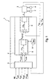
- Fig. 1 schematically represents an embodiment of a device according to the invention again.
- the device comprises a regulator device 1, with which an actuator 2 of an electromechanically actuated brake via a control variable U, for example, a voltage is controlled.
- U for example, a voltage
- the application force F is the brake measured.
- the respective current actuator position is ⁇ is measured by a position measuring system 8.
- the Aktuatorpositionsunk can be realized by measuring an angle, for example, the actuator or a transmission downstream of the actuator, or a position, for example, an axial position of a spindle driven by the actuator.
- the actuator speed n is (or actuator speed) is formed, for example, by differentiating the signal of the position measuring system 8 corresponding to the measured actuator position. Alternatively or additionally, the actuator speed n is also measured with an additional actuator speed sensor.
- Control device 1 comprises a selection and evaluation device 3 and a controller structure 4.
- Selection and evaluation 3 are as inputs a control mode parameter MX, which determines the desired control mode (force control or position control or speed control) of the regulator device 1, and at least one target value F soll , ⁇ soll , ⁇ soll , n should be supplied as a reference variable for the control.
- the selection and evaluation device 3 Independently of the control mode, the selection and evaluation device 3 outputs a desired value ⁇ in-soll and an actual value ⁇ in-is a predetermined actuator variable (eg actuator position ⁇ or actuator clamping force F or actuator speed n), which the controller structure 4 as controller structure input setpoint and controller structure Input actual value (controller structure input variables).
- actuator variable eg actuator position ⁇ or actuator clamping force F or actuator speed n
- the preset actuator variable is the actuator position
- the selection and evaluation device 3 outputs a position desired value and a position actual value as controller structure input setpoint value ⁇ in-soll and controller structure input actual value ⁇ in-ist at controller structure 4.
- the selection and evaluation device 3, as an example, according to the input variables are also the Aktuatorspannkraft actual value F is and the Aktuatorposition actual value ⁇ is supplied.
- Controller structure 4 includes, for example, a position controller 5 (P controller) and a speed controller 6 (PI controller) connected downstream of the position controller 5.
- Position controller 5 outputs, as output variable, an actuator speed setpoint n off-soll , which is transferred as an input variable to the downstream speed controller 6.
- the speed controller 6 is supplied as input of the actuator speed actual value n ist .
- Aktuator horrinum may be present 9, n outputted from the position controller 5 actuator velocity setpoint from setpoint n max limited to a predetermined maximum value, to protect the actuator 2 from being damaged.
- Fig. 1 illustrated device or the implementation of a method according to the invention is hereinafter, in particular in connection with Fig. 2 and 3 , explained in more detail.
- Fig. 2 schematically an embodiment of a method according to the invention for performing a force control is shown.
- the regulator device 1 at least one Aktuatorspannkraft actual value F, and a Aktuatorspannkraft setpoint F should fed as input variables.
- a corresponding actual value ⁇ in is determined from the actuator tensioning force actual value F ist and the actuator tensioning force setpoint F soll and a corresponding desired value ⁇ in-soll is determined for the actuator position. This is done with the help of a given functional Relationship f between the actuator position ⁇ and the Aktuatorspannkraft F, which is characteristic of the brake used.
- the functional relationship f which in Fig.
- Position controller 5 has the task that the actual value ⁇ in-ist the setpoint ⁇ in-soll follows, ie that the position error ⁇ 5 is zero.
- the output of the position controller 5 is a corresponding setpoint n aus-soll for the subsequent speed controller 6.
- the speed controller 6 evaluates the deviation .DELTA.n 6 between the Aktuator Norway setpoint n out-soll and the Aktuator für actual value n is , which also supplied to the speed controller 6 is, and outputs a corresponding manipulated variable U to the actuator 2 (see Fig. 1 ).
- Fig. 3 schematically an embodiment of a method according to the invention for performing a speed control is shown.
- a velocity control (indicated by a parameter control mode M2) to the regulator device 1
- the selection and evaluation device 3 in-soll is determined for the actuator in such a way from the actuator speed nominal value n to a target value of ⁇ that the following of the position regulator 5 output actuator speed setpoint n out-should correspond to the selection and evaluation device 3 supplied Aktuator Malawi setpoint n soll .
- the actuator speed setpoint n soll is divided by the gain K p (block 10) and the actuator position actual value ⁇ is added (block 11) ).
- the result is fed to the position controller 5 as setpoint value ⁇ in-soll together with the actuator position actual value ⁇ is as controller structure input variables ⁇ in-soll , ⁇ in-ist . It then follows a regulation by position controller 5 and speed controller 6 as in connection with Fig. 2 explained.
- a position control can be distinguished between two types of control: a "relative" position control (characterized by a control mode parameter M3), in which the regulator device 1 in addition to the Aktuatorposition actual value ⁇ is a relative Aktuatorposition-target value ⁇ soll is supplied as input, wherein the relative Aktuatorposition setpoint ⁇ soll corresponds to a desired actuator position change, as well as an "absolute" position control (characterized by a control mode parameter M4), in which the regulator device 1 in addition to the Aktuatorposition actual value ⁇ is an absolute Aktuatorposition setpoint ⁇ soll supplied as input is, wherein the Aktuatorposition setpoint ⁇ soll corresponds to the desired absolute actuator position.
- a "relative" position control characterized by a control mode parameter M3
- the regulator device 1 in addition to the Aktuatorposition actual value ⁇ is a relative Aktuatorposition-target value ⁇ soll is supplied as input
- the relative Aktuatorposition setpoint ⁇ soll corresponds to
- the actuator position ⁇ is temporarily stored temporarily in a temporary memory, for example in the selection and evaluation device 3, so that upon entry into the "relative" position control M3 an actuator position value ⁇ store is available from a time shortly before the entry into the position control M3.
- the actuator position desired value and actual value ⁇ soll fed to the selection and evaluation device 3 is simply fed directly to the position controller 5 as controller structure input setpoint value ⁇ in-soll and controller structure input actual value ⁇ in-ist .
- the selection and evaluation device 3 provides the controller structure input quantities ⁇ in-soll , ⁇ in-is such for the controller structure 4 that the controller device 1 with the same controller structure 4 is a force controller for setting an actuator clamping force setpoint or a position control for setting a Aktuatorposition setpoint or a speed control for setting an Aktuator loftiere setpoint can perform.
- Control device 1 represents a dynamic balancing device and ensures that according to the selected control mode force control M1 or speed control M2 or position control M3, M4, the clamping force or the actuator speed or the actuator position of the corresponding reference variable Aktuatorspannkraft setpoint F soll , actuator speed setpoint n soll or (absolute or relative) Aktuatorposition setpoint ⁇ soll , ⁇ soll follows.
- Brake system 20 comprises a central control unit ECU and at least one electrically operable brake 22, which can be actuated by an actuator 2, which is controlled by a control device 1.
- a control device 1 which controls the central control unit ECU.
- the central control unit ECU is connected to the regulator devices 1 (connections 21 are in Fig. 4 shown schematically).
- the central control unit ECU is based on the control unit ECU information and requirements, such as driver brake request, requirements of a slip control system (ABS: antilock braking system, TCS: traction control system) or driver assistance system (ESC: electronic stability control), Initialtechnischsanbig, request for L fullyinstituingna, etc., a decision on the desired control mode (force control M1 or speed control M2 or position control M3, M4) made, which is passed in the form of the control mode parameter MX to the regulator devices 1. Furthermore, the central control unit ECU the control devices 1 according to the requirement and the desired control mode, a setpoint (F soll , ⁇ soll , ⁇ soll , n soll ) as a reference variable for the scheme before.
- a setpoint F soll , ⁇ soll , ⁇ soll , n soll
- a regulator device which can perform the described types of control modes M1-M4, is advantageous in order to be able to fulfill various requirements for the brake.
- a force control is performed, for example, to set the desired braking force by the driver or slip-controlled braking.
- a position control is performed, for example, to adjust the clearance in a disc brake, ie, the distance between the brake disc and the displaceable brake pad to a predetermined value.
- a position control is performed to bring the actuator in the proper position for engaging the lock.
- a speed control can be performed, for example, to determine the stop of the actuator facing away from the brake pads.
Landscapes
- Engineering & Computer Science (AREA)
- Transportation (AREA)
- Mechanical Engineering (AREA)
- Regulating Braking Force (AREA)
- Braking Systems And Boosters (AREA)
- Control Of Electric Motors In General (AREA)
Description
- Die Erfindung betrifft ein Verfahren zur Regelung einer mittels eines Aktuators elektrisch betätigbaren Bremse gemäß dem Oberbegriff von Anspruch 1 und eine Vorrichtung gemäß dem Oberbegriff von Anspruch 11. Sie betrifft ferner ein elektronisches Bremssystem mit einer derartigen Vorrichtung.
- Ein Verfahren sowie ein Regelsystem zum Aufbringen definierter Spannkräfte bei einer mittels eines Elektromotors betätigbaren Scheibenbremse sind aus der internationalen Patentanmeldung
WO 05/100114 - In der
DE 103 02 515 A1 wird eine Vorrichtung und ein Verfahren zur Kraft- und Positionsregelung eines elektrischen Bremssystems eines Kraftfahrzeugs beschrieben. Die Regelkreisstruktur kann in zwei Betriebsarten, Kraftregelung oder Positionsregelung, betrieben werden, wobei der Wechsel zwischen den Betriebsarten durch einen Schalter erfolgt, wodurch der Position-Sollwert für den Motorregler entweder von einem Kraftregler oder von einer weiteren Einheit bereitgestellt wird. Die beschriebene Regelkreisstruktur besitzt somit sozusagen zwei parallele Einheiten (Kraftregler und weitere Einheit), wobei für eine vorgegebene Betriebsart nur eine der beiden Einheiten verwendet wird. - Es ist daher Aufgabe der vorliegenden Erfindung, ein Verfahren sowie eine Vorrichtung zur Regelung einer mittels eines Aktuators elektrisch betätigbaren Bremse vorzuschlagen, welches/welche mit einer einheitlichen, insbesondere einfachen, Reglervorrichtung eine situationsangepasste Regelung durchführen kann.
- Diese Aufgabe wird erfindungsgemäß durch ein Verfahren gemäß Anspruch 1 sowie eine Vorrichtung gemäß Anspruch 11 gelöst.
- Der Erfindung liegt der Gedanke zugrunde, dass die Reglervorrichtung neben einer vorgegebenen einheitlichen Reglerstruktur, welcher eine vorgegebenen Art von Reglerstruktur-Eingangsgrößen zugeführt werden, eine Auswahl- und Auswerteeinrichtung umfasst, welche aus den Eingangsgrößen der Reglervorrichtung die geeigneten Reglerstruktur-Eingangsgrößen bestimmt, so dass die Reglervorrichtung trotz einer fest vorgegebenen Reglerstruktur zumindest zwei verschiedene Regelungsmodi, wie Kraftregelung oder Geschwindigkeitsregelung oder Positionsregelung, durchführen kann.
- Unter dem Begriff Aktuatorposition wird erfindungsgemäß neben einer Position, z.B. der axialen Position einer Spindel des Aktuators, auch ein Winkel, z.B. der Winkel eines Rotors des Aktuators, oder eine andere die Position charakterisierende Größe verstanden.
- Ein Vorteil der Erfindung liegt darin, dass bei gleicher Funktionalität die Anzahl der benötigten Regler/Einheiten gegenüber den bekannten Regelkreisstrukturen reduziert werden kann und somit die Herstellungskosten reduziert werden können.
- Ein weiterer Vorteil der Erfindung liegt in der einheitlichen einfachen Struktur, welche eine einfachere Ansteuerung zur Folge hat, z.B. wenn die Reglervorrichtung neu initialisiert werden soll.
- Des Weiteren ist ein Wechseln zwischen Regelungsmodi durch die einheitliche Struktur einfach möglich, ohne z.B. Schaltvorgänge im Regler selbst durchführen zu müssen. So wird das Auftreten von undefinierten Reglerzuständen vermieden.
- Bevorzugt ist die Reglervorrichtung mit derselben Reglerstruktur in zumindest drei Regelungsmodi, Kraftregelung oder Positionsregelung oder Geschwindigkeitsregelung, betreibbar.
- Um eine Auswahl des Regelungsmodus zu ermöglichen, wird der Auswahl- und Auswerteeinrichtung bevorzugt als Eingangsgröße ein Regelungsmodus-Parameter zugeführt, durch welchen der von der Reglervorrichtung durchzuführende Regelungsmodus bestimmt wird. Die weiteren Eingangsgrößen der Auswahl- und Auswerteeinrichtung hängen von dem Regelungsmodus-Parameter ab, wobei der Auswahl- und Auswerteeinrichtung zumindest ein Aktuator-Istwert und zumindest ein Aktuator-Sollwert bereitgestellt werden. Besonders bevorzugt werden der Auswahl- und Auswerteeinrichtung unabhängig vom Regelungsmodus-Parameter Istwerte für die Aktuatorspannkraft und die Aktuatorposition zugeführt, wobei die Auswahl- und Auswerteeinrichtung nur den für den jeweiligen Regelungsmodus benötigten Istwert zur Auswertung heranzieht.
- Gemäß einer bevorzugten Ausführungsform der Erfindung umfasst die Reglerstruktur zumindest einen Positionsregler und die Auswahl- und Auswerteeinrichtung stellt der Reglerstruktur in jedem Regelungsmodus eine Aktuatorposition als Reglerstruktur-Eingangssollwert und Reglerstruktur-Eingangsistwert bereit.
- Gemäß einer vorteilhaften Weiterbildung der Erfindung umfasst die Reglerstruktur einen Positionsregler mit einen dem Positionsregler nachgeschalteten Geschwindigkeitsregler. Dem Geschwindigkeitsregler werden dann als Eingangsgrößen ein von dem Positionsregler ausgegebener Aktuatorgeschwindigkeit-Sollwert und der Aktuatorgeschwindigkeit-Istwert zugeführt. Besonders bevorzugt umfasst die Reglerstruktur keinen weiteren Regler, so dass der Geschwindigkeitsregler die Stellgröße für den Aktuator ausgibt. Vorteilhafterweise umfasst der Positionsregler eine Geschwindigkeitsbegrenzung, welche den vom Positionsregler ausgegebenen Aktuatorgeschwindigkeit-Sollwert auf einen vorgegebenen Maximalwert begrenzt, um so den Aktuator vor Beschädigung zu schützen.
- Zur Durchführung einer Kraftregelung werden entsprechend einer bevorzugten Ausführungsform eines erfindungsgemäßen Verfahrens in der Auswahl- und Auswerteeinrichtung anhand eines vorgegebenen Zusammenhangs zwischen Aktuatorposition und Aktuatorspannkraft aus dem der Auswahl- und Auswerteeinrichtung zugeführten Aktuatorspannkraft-Sollwert ein Sollwert für die Aktuatorposition und aus dem der Auswahl- und Auswerteeinrichtung zugeführten Aktuatorspannkraft-Istwert ein Istwert für die Aktuatorposition bestimmt. Diese bestimmten Soll- und Istwerte für die Aktuatorposition werden als Reglerstruktur-Eingangssollwert und Reglerstruktur-Eingangsistwert an den Positionsregler ausgegeben.
- Für eine schnelle Bestimmung der Soll- und Istwerte für die Aktuatorposition ist der vorgegebenen Zusammenhang zwischen Aktuatorposition und Aktuatorspannkraft bevorzugt in Form einer Tabelle in der Auswahl- und Auswerteeinrichtung abgelegt.
- Gemäß einer weiteren bevorzugten Ausführungsform eines erfindungsgemäßen Verfahrens werden zur Geschwindigkeitsregelung der Auswahl- und Auswerteeinrichtung ein Aktuatorgeschwindigkeit-Sollwert und ein Aktuatorposition-Istwert zugeführt. Aus dem Aktuatorgeschwindigkeit-Sollwert wird in der Auswahl- und Auswerteeinrichtung ein Sollwert für die Aktuatorposition bestimmt, welcher zusammen mit dem Aktuatorposition-Istwert an den Positionsregler ausgegeben wird.
- Im Falle eines dem Positionsregler nachgeschalteten Geschwindigkeitsreglers wird bei einer Geschwindigkeitsregelung der Sollwert für die Aktuatorposition in der Auswahl- und Auswerteeinrichtung bevorzugt derart aus dem Aktuatorgeschwindigkeit-Sollwert bestimmt, dass der von dem Positionsregler ausgegebene Aktuatorgeschwindigkeit-Sollwert dem Aktuatorgeschwindigkeit-Sollwert entspricht, welcher der Auswahl- und Auswerteeinrichtung zugeführt wurde. So kann durch eine vorgegebene Reglerstruktur mit einem externen Positionsregler und einem internen Geschwindigkeitsregler eine Geschwindigkeitsregelung durchgeführt werden.
Bevorzugt ist die Reglervorrichtung in einem Regelungsmodus mit relativer Positionsregelung betreibbar. Hierzu werden der Auswahl- und Auswerteeinrichtung ein relativer Aktuatorposition-Sollwert, welcher eine gewünschte Positionsänderung wiedergibt, und ein Aktuatorposition-Istwert zugeführt. Die Auswahl- und Auswerteeinrichtung bestimmt durch Addition aus dem relativen Aktuatorposition-Sollwert und einem vor Eintritt in den relativen Positionsregelungsmodus abgespeicherten Aktuatorposition-Wert einen Sollwert für die Aktuatorposition, welcher zusammen mit dem Aktuatorposition-Istwert an den Positionsregler ausgegeben wird. - Bevorzugt ist die Reglervorrichtung alternativ oder zusätzlich in einem Regelungsmodus mit absoluter Positionsregelung betreibbar, in welcher der Auswahl- und Auswerteeinrichtung zumindest ein Aktuatorposition-Sollwert und ein Aktuatorposition-Istwert zugeführt werden, welche als Reglerstruktur-Eingangssollwert und Reglerstruktur-Eingangsistwert dem Positionsregler der Reglerstruktur zugeführt werden.
- Gemäß einer bevorzugten Ausführungsform der Erfindung werden der Regelungsmodus-Parameter und der mindestens eine Aktuator-Sollwert der Auswahl- und Auswerteeinrichtung von einer übergeordneten elektronischen Steuer- und Regeleinheit zugeführt. Der übergeordneten elektronischen Steuer- und Regeleinheit liegen üblicherweise Informationen und/oder Anforderungen vor, z.B. bezüglich des Fahrerbremswunschs, Anforderungen eines Schlupfregelsystems (ABS: Antiblockiersystems, TCS: Traktionsregelsystem) oder Fahrerassistenzsystems (ESC: electronic stability control), Initialisierungsanforderung, Anforderung zur Lüftspieleinstellung etc., so dass in der übergeordneten elektronischen Steuer- und Regeleinheit über eine passende Regelung der Bremse entschieden werden kann und der entsprechende Aktuator-Sollwert bestimmt wird.
- Die Erfindung betrifft auch ein elektronisches Bremssystem für ein Kraftfahrzeug mit zumindest einer mittels eines Aktuators elektrisch betätigbaren Bremse und mit einer Steuer- und Regeleinheit, wobei die Steuer- und Regeleinheit zumindest eine erfindungsgemäße Vorrichtung aufweist oder mit zumindest einer erfindungsgemäßen Vorrichtung verbunden ist.
- Weitere bevorzugte Ausführungsformen der Erfindung ergeben sich aus den Unteransprüchen und der nachfolgenden Beschreibung anhand von Figuren.
- Es zeigen schematisch:
- Fig. 1
- ein Ausführungsbeispiel einer erfindungsgemäßen Vorrichtung,
- Fig. 2
- ein Ausführungsbeispiel eines erfindungsgemäßen Verfahrens zur Durchführung einer Kraftregelung,
- Fig. 3
- ein Ausführungsbeispiel eines erfindungsgemäßen Verfahrens zur Durchführung einer Geschwindigkeitsregelung, und
- Fig. 4
- ein Ausführungsbeispiel eines erfindungsgemäßen elektronischen Bremssystems.
-
Fig. 1 gibt schematisch ein Ausführungsbeispiel einer erfindungsgemäßen Vorrichtung wieder. Die Vorrichtung umfasst eine Reglervorrichtung 1, mit welcher ein Aktuator 2 einer elektromechanisch betätigbaren Bremse über eine Stellgröße U, z.B. eine Spannung, angesteuert wird. Mittels eines Spannkraftsensors 7 wird die Zuspannkraft Fist der Bremse gemessen. Zudem wird die jeweils aktuelle Aktuatorposition ϕist durch ein Positionsmesssystem 8 gemessen. Die Aktuatorpositionsmessung kann durch Messung eines Winkels, z.B. des Aktuators oder eines dem Aktuator nachgeschalteten Getriebes, oder einer Position, z.B. einer axialen Position einer von dem Aktuator angetriebenen Spindel, realisiert sein. Die Aktuatorgeschwindigkeit nist (bzw. Aktuatordrehzahl) wird beispielsgemäß durch Differenzieren des der gemessenen Aktuatorposition entsprechenden Signals des Positionsmesssystems 8 gebildet. Alternativ oder zusätzlich kann die Aktuatorgeschwindigkeit nist auch mit einem zusätzlichen Aktuatorgeschwindigkeitsensor gemessen werden. - Reglervorrichtung 1 umfasst eine Auswahl- und Auswerteeinrichtung 3 und eine Reglerstruktur 4. Auswahl- und Auswerteeinrichtung 3 werden als Eingangsgrößen ein Regelungsmodus-Parameter MX, welcher den gewünschte Regelungsmodus (Kraftregelung oder Positionsregelung oder Geschwindigkeitsregelung) der Reglervorrichtung 1 bestimmt, und zumindest ein Sollwert Fsoll, ϕsoll, Δϕsoll, nsoll als Führungsgröße für die Regelung zugeführt. Die Auswahl- und Auswerteeinrichtung 3 gibt unabhängig von dem Regelungsmodus einen Sollwert ϕin-soll und einen Istwert ϕin-ist einer vorgegebenen Aktuatorgröße (z.B. Aktuatorposition ϕ oder Aktuatorzuspannkraft F oder Aktuatorgeschwindigkeit n) aus, welche der Reglerstruktur 4 als Reglerstruktur-Eingangssollwert und Reglerstruktur-Eingangsistwert (Reglerstruktur-Eingangsgrößen) zugeführt werden. Beispielsgemäß handelt es sich bei der vorgegebenen Aktuatorgröße um die Aktuatorposition, d.h. die Auswahl- und Auswerteeinrichtung 3 gibt einen Position-Sollwert und einen Position-Istwert als Reglerstruktur-Eingangssollwert ϕin-soll und Reglerstruktur-Eingangsistwert ϕin-ist an Reglerstruktur 4 aus. Der Auswahl- und Auswerteeinrichtung 3 werden als Eingangsgrößen beispielsgemäß außerdem der Aktuatorspannkraft-Istwert Fist und der Aktuatorposition-Istwert ϕist zugeführt.
- Reglerstruktur 4 umfasst beispielsgemäß einen Positionsregler 5 (P-Regler) und einen dem Positionsregler 5 nachgeschalteten Geschwindigkeitsregler 6 (PI-Regler). Positionsregler 5 gibt als Ausgangsgröße einen Aktuatorgeschwindigkeit-Sollwert naus-soll aus, welcher als Eingangsgröße an den nachgeschalteten Geschwindigkeitsregler 6 übergeben wird. Außerdem wird Geschwindigkeitsregler 6 als Eingangsgröße der Aktuatorgeschwindigkeit-Istwert nist zugeführt.
- Optional kann eine Aktuatorgeschwindigkeitsbegrenzung 9 vorhanden sein, welche den von Positionsregler 5 ausgegebenen Aktuatorgeschwindigkeit-Sollwert naus-soll auf einen vorgegebenen Maximalwert nmax begrenzt, um den Aktuator 2 vor Beschädigung zu schützen.
- Die Funktionsweise der in
Fig. 1 dargestellten Vorrichtung bzw. die Durchführung eines erfindungsgemäßen Verfahrens wird nachfolgend, insbesondere im Zusammenhang mitFig. 2 und3 , näher erläutert. - In
Fig. 2 ist schematisch ein Ausführungsbeispiel eines erfindungsgemäßen Verfahrens zur Durchführung einer Kraftregelung dargestellt. Bei einer Kraftregelung (gekennzeichnet durch einen Regelungsmodus-Parameter M1) werden der Reglervorrichtung 1 zumindest ein Aktuatorspannkraft-Istwert Fist und ein Aktuatorspannkraft-Sollwert Fsoll als Eingangsgrößen zugeführt. In der Auswahl- und Auswerteeinrichtung 3 werden aus dem Aktuatorspannkraft-Istwert Fist und dem Aktuatorspannkraft-Sollwert Fsoll ein entsprechender Istwert ϕin-ist und ein entsprechender Sollwert ϕin-soll für die Aktuatorposition bestimmt. Dies geschieht mit Hilfe eines vorgegebenen funktionalen Zusammenhangs f zwischen der Aktuatorposition ϕ und der Aktuatorspannkraft F, welcher charakteristisch für die verwendete Bremse ist. Der funktionale Zusammenhang f, welcher inFig. 2 schematisch als Kennlinie dargestellt ist, kann z.B. in Form einer Tabelle oder in Form einer mathematischen Formel vorgegeben sein. Die anhand des funktionalen Zusammenhangs f bestimmten Ist- und Sollwert ϕin-ist, ϕin-soll werden dem Positionsregler 5 zugeführt, welcher als P-Regler mit einem proportionalen Anteil der Verstärkung Kp ausgeführt ist. In Positionsregler 5 wird die Differenz aus Sollwert ϕin-soll und Istwert ϕin-ist gebildet, welche als Positionsfehler Δϕ5 bezeichnet ist. Positionsregler 5 hat die Aufgabe, dass der Istwert ϕin-ist dem Sollwert ϕin-soll folgt, d.h. dass der Positionsfehler Δϕ5 Null wird. Der Ausgang des Positionsreglers 5 ist ein entsprechender Sollwert naus-soll für den nachfolgenden Geschwindigkeitsregler 6. Der Geschwindigkeitsregler 6 bewertet die Abweichung Δn6 zwischen dem Aktuatorgeschwindigkeit-Sollwert naus-soll und dem Aktuatorgeschwindigkeit-Istwert nist, welche dem Geschwindigkeitsregler 6 ebenfalls zugeführt wird, und gibt eine entsprechende Stellgröße U an den Aktuator 2 aus (sieheFig. 1 ). -
Fig. 3 ist schematisch ein Ausführungsbeispiel eines erfindungsgemäßen Verfahrens zur Durchführung einer Geschwindigkeitsregelung dargestellt. Bei einer Geschwindigkeitsregelung (gekennzeichnet durch einen Regelungsmodus-Parameter M2) werden der Reglervorrichtung 1 zumindest ein Aktuatorposition-Istwert ϕist und ein Aktuatorgeschwindigkeit-Sollwert nsoll als Eingangsgrößen zugeführt. In der Auswahl- und Auswerteeinrichtung 3 wird aus dem Aktuatorgeschwindigkeit-Sollwert nsoll ein Sollwert ϕin-soll für die Aktuatorposition derart bestimmt, dass der von dem nachfolgenden Positionsregler 5 ausgegebene Aktuatorgeschwindigkeit-Sollwert naus-soll dem der Auswahl- und Auswerteeinrichtung 3 zugeführten Aktuatorgeschwindigkeit-Sollwert nsoll entspricht. Hierzu wird in dem Fall, dass der Positionsregler 5 als ein P-Regler mit einer Verstärkung Kp ausgeführt ist, der Aktuatorgeschwindigkeit-Sollwert nsoll durch die Verstärkung Kp geteilt (Block 10) und zum Aktuatorposition-Istwert ϕist hinzuaddiert (Block 11). Das Ergebnis wird dem Positionsregler 5 als Sollwert ϕin-soll zusammen mit dem Aktuatorposition-Istwert ϕist als Reglerstruktur-Eingangsgrößen ϕin-soll, ϕin-ist zugeführt. Es folgt dann eine Regelung durch Positionsregler 5 und Geschwindigkeitsregler 6 wie im Zusammenhang mitFig. 2 erläutert. - Bei einer Positionsregelung kann zwischen zwei Regelungsarten unterschieden werden: eine "relative" Positionsregelung (gekennzeichnet durch einen Regelungsmodus-Parameter M3), in welcher der Reglervorrichtung 1 neben dem Aktuatorposition-Istwert ϕist ein relativer Aktuatorposition-Sollwert Δϕsoll als Eingangsgröße zugeführt wird, wobei der relative Aktuatorposition-Sollwert Δϕsoll einer gewünschten Aktuatorpositionsänderung entspricht, sowie eine "absolute" Positionsregelung (gekennzeichnet durch einen Regelungsmodus-Parameter M4), in welcher der Reglervorrichtung 1 neben dem Aktuatorposition-Istwert ϕist ein absoluter Aktuatorposition-Sollwert ϕsoll als Eingangsgröße zugeführt wird, wobei der Aktuatorposition-Sollwert Δϕsoll der gewünschten absoluten Aktuatorposition entspricht.
- Für die "relative" Positionsregelung M3 wird die Aktuatorposition ϕist in einem Zwischenspeicher, z.B. in der Auswahl- und Auswerteeinrichtung 3, temporär zwischengespeichert, so dass bei einem Eintritt in die "relative" Positionsregelung M3 ein Aktuatorposition-Wert ϕstore von einem Zeitpunkt kurz vor dem Eintritt in die Positionsregelung M3 verfügbar ist. Zur "relativen" Positionsregelung wird dann in der Auswahl- und Auswerteeinrichtung 3 aus dem relativen Aktuatorposition-Sollwert Δϕsoll und dem vor Eintritt in den Regelungsmodus M3 abgespeicherten Aktuatorposition-Wert ϕstore ein Reglerstruktur-Eingangssollwert ϕin-soll durch Addition gemäß

bestimmt und an den Positionsregler 5 ausgegeben. - Bei der "absoluten" Positionsregelung M4 werden der der Auswahl- und Auswerteeinrichtung 3 zugeführte Aktuatorposition-Sollwert und -Istwert ϕsoll, ϕist einfach direkt dem Positionsregler 5 als Reglerstruktur-Eingangssollwert ϕin-soll und Reglerstruktur-Eingangsistwert ϕin-ist zugeführt.
- Zusammenfassend kann man also sagen, dass die Auswahl- und Auswerteeinrichtung 3 die Reglerstruktur-Eingangsgrößen ϕin-soll, ϕin-ist derart für die Reglerstruktur 4 bereitstellt, dass Reglervorrichtung 1 mit der selben Reglerstruktur 4 eine Kraftregelung zur Einstellung eines Aktuatorspannkraft-Sollwertes oder eine Positionsregelung zur Einstellung eines Aktuatorposition-Sollwertes oder eine Drehzahlregelung zur Einstellung eines Aktuatordrehzahl-Sollwertes durchführen kann.
- Reglervorrichtung 1 stellt eine dynamische Abgleicheinrichtung dar und sorgt dafür, dass entsprechend dem gewählten Regelungsmodus Kraftregelung M1 oder Geschwindigkeitsregelung M2 oder Positionsregelung M3, M4 die Zuspannkraft oder die Aktuatorgeschwindigkeit oder die Aktuatorposition der entsprechenden Führungsgröße Aktuatorspannkraft-Sollwert Fsoll, Aktuatorgeschwindigkeit-Sollwert nsoll oder (absoluter bzw. relativer) Aktuatorposition-Sollwert ϕsoll, Δϕsoll folgt.
- In
Fig. 4 ist ein Ausführungsbeispiel eines erfindungsgemäßen elektronischen Bremssystems rein schematisch dargestellt. Bremssystem 20 umfasst eine zentrale Kontrolleinheit ECU und zumindest eine elektrisch betätigbare Bremse 22, welche von einem Aktuator 2 betätigbar ist, der von einer Reglervorrichtung 1 gesteuert bzw. geregelt wird. InFig. 4 sind beispielsgemäß vier Radbremsen 22 mit jeweils einem Aktuator 2 und einer zugehörigen Reglervorrichtung 1 dargestellt. Die zentrale Kontrolleinheit ECU ist mit den Reglervorrichtungen 1 verbunden (Verbindungen 21 sind inFig. 4 schematisch dargestellt). In der zentralen Kontrolleinheit ECU wird anhand der der Kontrolleinheit ECU vorliegenden Informationen und Anforderungen, wie z.B. Fahrerbremswunsch, Anforderungen eines Schlupfregelsystems (ABS: Antiblockiersystems, TCS: Traktionsregelsystem) oder Fahrerassistenzsystems (ESC: electronic stability control), Initialisierungsanforderung, Anforderung zur Lüftspieleinstellung etc., eine Entscheidung über den gewünschten Regelungsmodus (Kraftregelung M1 oder Geschwindigkeitsregelung M2 oder Positionsregelung M3, M4) getroffen, welche in Form des Regelungsmodus-Parameter MX an die Reglervorrichtungen 1 weitergegeben wird. Weiterhin gibt die zentrale Kontrolleinheit ECU den Reglervorrichtungen 1 entsprechend der Anforderung und des gewünschten Regelungsmodus einen Sollwert (Fsoll, ϕsoll, Δϕsoll, nsoll) als Führungsgröße für die Regelung vor. - Eine Reglervorrichtung, welche die beschriebenen Arten von Regelungsmodi M1-M4 durchführen kann, ist vorteilhaft, um verschiedene Anforderungen an die Bremse erfüllen zu können. So wird eine Kraftregelung z.B. zur Einstellung der vom Fahrer gewünschten Bremskraft oder bei schlupfgeregelten Bremsvorgängen durchgeführt. Eine Positionsregelung wird z.B. durchgeführt, um das Lüftspiel bei einer Scheibenbremse, d.h. den Abstand zwischen der Bremsscheibe und dem verschiebbaren Bremsbelag, auf einen vorbestimmten Wert einzustellen. Um eine elektromechanische Bremse, welche einen mechanischen Verriegelungsmechanismus zur Realisierung einer Parkbremsfunktion umfasst, zu verriegeln, wird ebenfalls eine Positionsregelung durchgeführt, um den Aktuator in die passende Position zum Eingreifen der Verriegelung zu bringen. Eine Geschwindigkeitsregelung kann z.B. zur Bestimmung des den Bremsbelägen abgewandten Anschlags des Aktuators durchgeführt werden.
Claims (14)
- Verfahren zur Regelung einer mittels eines Aktuators (2) elektrisch betätigbaren Bremse, bei welchem mittels eines Spannkraftsensors (7) ein Aktuatorspannkraft-Istwert (Fist) und mittels eines Lagesensors (8) ein Aktuatorposition-Istwert (ϕist) und/oder ein Aktuatorgeschwindigkeit-Istwert (nist) ermittelt werden, und bei welchem mittels einer Reglervorrichtung (1) eine Stellgröße (U) zur Ansteuerung des Aktuators (2)erzeugt wird, dadurch gekennzeichnet, dass die Reglervorrichtung (1) eine Auswahl- und Auswerteeinrichtung (3) und eine Reglerstruktur (4) umfasst, wobei die Auswahl- und Auswerteeinrichtung (3) der Reglerstruktur (4) als Reglerstruktur-Eingangsgrößen einen Reglerstruktur-Eingangssollwert (ϕin-soll) und einen Reglerstruktur-Eingangsistwert (ϕin-ist) zuführt, und wobei die Reglerstruktur-Eingangsgrößen (ϕin-soll, ϕin-ist) derart von der Auswahl- und Auswerteeinrichtung (3) bereitgestellt werden, dass die Reglervorrichtung (1) mit der selben Reglerstruktur (4) in zumindest zwei der Regelungsmodi Kraftregelung (M1) zur Einstellung eines Aktuatorspannkraft-Sollwertes (Fsoll) oder Positionsregelung (M3, M4) zur Einstellung eines Aktuatorposition-Sollwertes (ϕsoll, Δϕsoll) oder Geschwindigkeitsregelung (M2) zur Einstellung eines Aktuatorgeschwindigkeit-Sollwertes (nsoll) betrieben werden kann.
- Verfahren nach Anspruch 1, dadurch gekennzeichnet, dass der Reglerstruktur (4) von der Auswahl- und Auswerteeinrichtung (3) als Reglerstruktur-Eingangsgrößen in jedem Regelungsmodus (M1, M2, M3, M4) dieselbe vorgegebene physikalische Aktuatorgröße (ϕ) zugeführt wird.
- Verfahren nach einem der Ansprüche 1 oder 2, dadurch gekennzeichnet, dass der Auswahl- und Auswerteeinrichtung (3) als Eingangsgrößen ein Regelungsmodus-Parameter (MX), welcher den von der Reglervorrichtung (1) durchzuführenden Regelungsmodus (M1, M2, M3, M4) bestimmt, und, insbesondere in Abhängigkeit von dem Regelungsmodus-Parameter (MX), zumindest ein Aktuator-Istwert (Fist, ϕist) und zumindest ein Aktuator-Sollwert (Fsoll, ϕsoll, Δϕsoll, nsoll) zugeführt werden.
- Verfahren nach Anspruch 3, dadurch gekennzeichnet, dass der Auswahl- und Auswerteeinrichtung (3) der Aktuatorspannkraft-Istwert (Fist) und der Aktuatorposition-Istwert (ϕist) zugeführt werden und dass die Auswahl- und Auswerteeinrichtung (3) in Abhängigkeit von dem Regelungsmodus-Parameter (MX) den Aktuatorspannkraft-Istwert (Fist) oder den Aktuatorposition-Istwert (ϕist) zur Bestimmung des Reglerstruktur-Eingangssollwertes (ϕin-soll) auswertet.
- Verfahren nach einem der Ansprüche 2 bis 4, dadurch gekennzeichnet, dass die Reglerstruktur (4) zumindest einen Positionsregler (5) umfasst und dass der Reglerstruktur (4) von der Auswahl- und Auswerteeinrichtung (3) als Reglerstruktur-Eingangsgrößen in jedem Regelungsmodus (M1, M2, M3, M4) eine Aktuatorposition (ϕ) für Reglerstruktur-Eingangssollwert (ϕin-soll) und Reglerstruktur-Eingangsistwert (ϕin-ist) zugeführt wird.
- Verfahren nach Anspruch 5, dadurch gekennzeichnet, dass die Reglerstruktur (4) einen Positionsregler (5) und einen dem Positionsregler (5) nachgeschalteten Geschwindigkeitsregler (6) umfasst, wobei dem Geschwindigkeitsregler (6) als Eingangsgrößen ein von dem Positionsregler (5) ausgegebener Aktuatorgeschwindigkeit-Sollwert (naus-soll) und der Aktuatorgeschwindigkeit-Istwert (nist) zugeführt werden.
- Verfahren nach Anspruch 5 oder 6, dadurch gekennzeichnet, dass in dem Regelungsmodus Kraftregelung (M1) der Auswahl- und Auswerteeinrichtung (3) zumindest ein Aktuatorspannkraft-Sollwert (Fsoll) und ein Aktuatorspannkraft-Istwert (Fist) zugeführt werden, dass in der Auswahl- und Auswerteeinrichtung (3) anhand eines vorgegebenen Zusammenhangs (f) zwischen Aktuatorposition (ϕ) und Aktuatorspannkraft (F) aus dem Aktuatorspannkraft-Sollwert (Fsoll) ein Reglerstruktur-Eingangssollwert (ϕin-soll) und aus dem Aktuatorspannkraft-Istwert (Fist) ein Reglerstruktur-Eingangsistwert (ϕin-ist) bestimmt werden, und dass der bestimmte Reglerstruktur-Eingangssollwert (ϕin-soll) und der bestimmte Reglerstruktur-Eingangsistwert (ϕin-ist) dem Positionsregler (5) der Reglerstruktur (4) als Reglerstruktur-Eingangsgrößen (ϕin-soll, ϕin-ist) zugeführt werden.
- Verfahren nach einem der Ansprüche 5 bis 7, dadurch gekennzeichnet, dass in dem Regelungsmodus Geschwindigkeitsregelung (M2) der Auswahl- und Auswerteeinrichtung (3) zumindest ein Aktuatorgeschwindigkeit-Sollwert (nsoll) und ein Aktuatorposition-Istwert (ϕist) zugeführt werden, dass in der Auswahl- und Auswerteeinrichtung (3) aus dem Aktuatorgeschwindigkeit-Sollwert (nsoll) ein Reglerstruktur-Eingangssollwert (ϕin-soll) bestimmt wird, und dass der bestimmte Reglerstruktur-Eingangssollwert (ϕin-soll) und der Aktuatorposition-Istwert (ϕist) dem Positionsregler (5) der Reglerstruktur (4) als Reglerstruktur-Eingangsgrößen (ϕin-soll, ϕin-ist) zugeführt werden.
- Verfahren nach Anspruch 8 rückbezogen auf Anspruch 6 oder 7, dadurch gekennzeichnet, dass der Reglerstruktur-Eingangssollwert (ϕin-soll) derart aus dem Aktuatorgeschwindigkeit-Sollwert (nsoll), welcher der Auswahl- und Auswerteeinrichtung (3) zugeführt wird, berechnet wird, dass der von dem Positionsregler (5) ausgegebener Aktuatorgeschwindigkeit-Sollwert (naus-soll) in etwa gleich dem Aktuatorgeschwindigkeit-Sollwert (nsoll) ist, welcher der Auswahl- und Auswerteeinrichtung (3) zugeführt wird.
- Verfahren nach einem der Ansprüche 5 bis 9, dadurch gekennzeichnet, dass die Reglervorrichtung (1) in einem Regelungsmodus (M3) mit relativer Positionsregelung betreibbar ist, in welcher der Auswahl- und Auswerteeinrichtung (3) zumindest ein relativer Aktuatorposition-Sollwert, welcher die gewünschte Positionsänderung (Δϕsoll) der Aktuatorposition angibt, und ein Aktuatorposition-Istwert (ϕist) zugeführt werden, dass in der Auswahl- und Auswerteeinrichtung (3) aus dem relativen Aktuatorposition-Sollwert (Δϕsoll) und einem vor Eintritt in den Regelungsmodus (M3) mit relativer Positionsregelung abgespeicherten Aktuatorposition-Wert (ϕstore) ein Reglerstruktur-Eingangssollwert (ϕin-soll) bestimmt wird, und dass der bestimmte Reglerstruktur-Eingangssollwert (ϕin-soll) und der Aktuatorposition-Istwert (ϕist) dem Positionsregler (5) der Reglerstruktur (4) als Reglerstruktur-Eingangsgrößen (ϕin-soll, ϕin-ist) zugeführt werden.
- Vorrichtung zur Regelung einer mittels eines Aktuators (2) elektrisch betätigbaren Bremse mit einem Spannkraftsensor (7) zur Ermittlung eines Aktuatorspannkraft-Istwertes (Fist), mit einem Lagesensor (8) zur Ermittlung eines Aktuatorposition-Istwertes (ϕist) und/oder eines Aktuatorgeschwindigkeit-Istwertes (nist) und mit einer Reglervorrichtung (1), welche eine Stellgröße (U) erzeugt, mit welcher der Aktuator (2) angesteuert wird, dadurch gekennzeichnet, dass die Reglervorrichtung (1) eine Auswahl- und Auswerteeinrichtung (3) und eine Reglerstruktur (4) umfasst, wobei der Reglerstruktur (4) als Reglerstruktur-Eingangsgrößen ein Reglerstruktur-Eingangssollwert (ϕin-soll) und ein Reglerstruktur-Eingangsistwert (ϕin-ist) von der Auswahl- und Auswerteeinrichtung (3) zugeführt werden, und wobei die Auswahl- und Auswerteeinrichtung (3) die Reglerstruktur-Eingangsgrößen (ϕin-soll, ϕin-ist) derart für die Reglerstruktur (4) bereitstellt, dass die Reglervorrichtung (1) mit der selben Reglerstruktur (4) in zumindest zwei der Regelungsmodi Kraftregelung (M1) zur Einstellung eines Aktuatorspannkraft-Sollwertes (Fsoll) oder Positionsregelung (M3, M4) zur Einstellung eines Aktuatorposition-Sollwertes (ϕsoll, Δϕsoll) oder Geschwindigkeitsregelung (M2) zur Einstellung eines Aktuatorgeschwindigkeit-Sollwertes (nsoll) betreibbar ist.
- Vorrichtung nach Anspruch 11, dadurch gekennzeichnet, dass die Auswahl- und Auswerteeinrichtung (3) derart ausgeführt ist, dass der Reglerstruktur (4) als Reglerstruktur-Eingangsgrößen von der Auswahl- und Auswerteeinrichtung (3) in jedem Regelungsmodus (M1, M2, M3, M4) dieselbe vorgegebene physikalische Aktuatorgröße (ϕ) für Reglerstruktur-Eingangssollwert und Reglerstruktur-Eingangsistwert zugeführt wird.
- Vorrichtung nach Anspruch 11 oder 12, dadurch gekennzeichnet, dass die Reglerstruktur (4) zumindest einen Positionsregler (5) und einen dem Positionsregler (5) nachgeschalteten Geschwindigkeitsregler (6) umfasst, wobei dem Positionsregler (5) von der Auswahl- und Auswerteeinrichtung (3) als Reglerstruktur-Eingangsgrößen in jedem Regelungsmodus (M1, M2, M3, M4) eine Aktuatorposition (ϕ) für Reglerstruktur-Eingangssollwert (ϕin-soll) und Reglerstruktur-Eingangsistwert (ϕin-ist) zugeführt wird, und wobei dem Geschwindigkeitsregler (6) als Eingangsgrößen ein von dem Positionsregler (5) ausgegebener Aktuatorgeschwindigkeit-Sollwert (naus-soll) und der Aktuatorgeschwindigkeit-Istwert (nist) zugeführt werden.
- Elektronisches Bremssystem (20) für ein Kraftfahrzeug mit zumindest einer mittels eines Aktuators (2) elektrisch betätigbaren Bremse (22) für eine Betriebs- und/oder Feststellbremsfunktion und mit einer Steuer- und Regeleinheit (ECU), dadurch gekennzeichnet, dass die Steuer- und Regeleinheit (ECU) zumindest eine Vorrichtung gemäß einem der Ansprüche 11 bis 13 aufweist oder mit zumindest einer Vorrichtung gemäß einem der Ansprüche 11 bis 13 verbunden (21) ist.
Priority Applications (1)
| Application Number | Priority Date | Filing Date | Title |
|---|---|---|---|
| EP11721018.7A EP2582561B1 (de) | 2010-06-15 | 2011-05-11 | Verfahren und vorrichtung zur regelung einer elektrisch betätigbaren bremse sowie elektronisches bremssystem |
Applications Claiming Priority (4)
| Application Number | Priority Date | Filing Date | Title |
|---|---|---|---|
| EP10464005 | 2010-06-15 | ||
| DE102010038306A DE102010038306A1 (de) | 2010-06-15 | 2010-07-23 | Verfahren und Vorrichtung zur Regelung einer elektrisch betätigbaren Bremse sowie elektronisches Bremssystem |
| EP11721018.7A EP2582561B1 (de) | 2010-06-15 | 2011-05-11 | Verfahren und vorrichtung zur regelung einer elektrisch betätigbaren bremse sowie elektronisches bremssystem |
| PCT/EP2011/057610 WO2011157492A1 (de) | 2010-06-15 | 2011-05-11 | Verfahren und vorrichtung zur regelung einer elektrisch betätigbaren bremse sowie elektronisches bremssystem |
Publications (2)
| Publication Number | Publication Date |
|---|---|
| EP2582561A1 EP2582561A1 (de) | 2013-04-24 |
| EP2582561B1 true EP2582561B1 (de) | 2014-11-19 |
Family
ID=45020132
Family Applications (1)
| Application Number | Title | Priority Date | Filing Date |
|---|---|---|---|
| EP11721018.7A Active EP2582561B1 (de) | 2010-06-15 | 2011-05-11 | Verfahren und vorrichtung zur regelung einer elektrisch betätigbaren bremse sowie elektronisches bremssystem |
Country Status (6)
| Country | Link |
|---|---|
| US (1) | US8606477B2 (de) |
| EP (1) | EP2582561B1 (de) |
| KR (1) | KR101726474B1 (de) |
| CN (1) | CN102947154B (de) |
| DE (1) | DE102010038306A1 (de) |
| WO (1) | WO2011157492A1 (de) |
Families Citing this family (6)
| Publication number | Priority date | Publication date | Assignee | Title |
|---|---|---|---|---|
| JP5637067B2 (ja) * | 2011-05-24 | 2014-12-10 | 株式会社アドヴィックス | 電動ブレーキ装置および電動ブレーキ装置の制御方法 |
| US10220824B2 (en) | 2014-09-25 | 2019-03-05 | Continental Automotive Systems, Inc. | Electronic brake support system for use when service brake system has failed or is degraded |
| US9311761B1 (en) | 2014-11-21 | 2016-04-12 | Continental Automotive Systems, Inc. | Vehicle load information system to determine road slope and load when trailer is added to vehicle |
| IT201600131985A1 (it) * | 2016-12-29 | 2018-06-29 | Freni Brembo Spa | Metodo di controllo di un’azione frenante esercitabile da una pinza freno su un organo meccanico di movimento di un veicolo e relativo sistema di controllo. |
| DE102019109977B4 (de) | 2018-05-15 | 2024-03-28 | Schaeffler Technologies AG & Co. KG | Verfahren zur Referenzierung eines Endanschlages eines hydrostatischen Kupplungsaktors |
| EP4201766A1 (de) * | 2021-12-22 | 2023-06-28 | Haldex Brake Products Aktiebolag | Bremsanlage für ein nutzfahrzeug |
Family Cites Families (22)
| Publication number | Priority date | Publication date | Assignee | Title |
|---|---|---|---|---|
| DE19502925A1 (de) | 1995-01-31 | 1996-08-01 | Teves Gmbh Alfred | Verfahren zum Betrieb eines elektronisch regelbaren Bremsbetätigungssystems |
| DE19538794A1 (de) | 1995-10-18 | 1997-04-24 | Teves Gmbh Alfred | Elektronisch regelbares Bremsbetätigungssystem |
| DE19730094A1 (de) * | 1997-07-14 | 1999-01-21 | Itt Mfg Enterprises Inc | System zum Steuern oder Regeln einer elektromechanischen Bremse |
| WO1999026822A1 (de) * | 1997-11-22 | 1999-06-03 | Continental Teves Ag & Co. Ohg | Elektromechanisches bremssystem |
| WO1999026829A1 (de) | 1997-11-22 | 1999-06-03 | Continental Teves Ag & Co. Ohg | Verfahren und system zur ansteuerung einer elektromechanisch betätigbaren feststellbremse für kraftfahrzeuge |
| WO2001068428A1 (de) | 2000-03-15 | 2001-09-20 | Continental Teves Ag & Co. Ohg | Verfahren und regelsystem zum aufbringen definierter spannkräfte |
| JP4654547B2 (ja) | 2001-07-24 | 2011-03-23 | トヨタ自動車株式会社 | ブレーキ装置 |
| JP2003194119A (ja) * | 2001-12-28 | 2003-07-09 | Nissan Motor Co Ltd | 電動ブレーキ装置 |
| US7018001B2 (en) | 2002-02-22 | 2006-03-28 | Delphi Technologies, Inc. | Fast mode release in a force generating apparatus |
| DE10302515B4 (de) | 2003-01-23 | 2014-09-25 | Robert Bosch Gmbh | Vorrichtung und Verfahren zur Kraft- und/oder Positionsregelung eines elektrischen Bremssystems eines Kraftfahrzeugs |
| DE102005011267A1 (de) | 2004-04-17 | 2006-03-30 | Continental Teves Ag & Co. Ohg | Verfahren und Regelsystem zum Aufbringen definierter Spannkräfte |
| DE102005007446A1 (de) * | 2004-04-17 | 2005-11-17 | Continental Teves Ag & Co. Ohg | Verfahren und Regelsystem zum Aufbringen definierter Spannkräfte |
| WO2005119083A1 (en) * | 2004-06-04 | 2005-12-15 | Goodrich Corporation | Electric brake position and force sensing and control |
| JP4155236B2 (ja) * | 2004-07-09 | 2008-09-24 | トヨタ自動車株式会社 | 車両用駆動装置の制御装置 |
| JP4430508B2 (ja) | 2004-10-18 | 2010-03-10 | 本田技研工業株式会社 | ブレーキ装置 |
| DE102005055751B4 (de) | 2005-04-21 | 2018-09-06 | Ipgate Ag | Druckmodulatorsteuerung |
| DE102006040424A1 (de) | 2006-08-29 | 2008-03-06 | Continental Teves Ag & Co. Ohg | Bremssystem für Kraftfahrzeuge |
| JP4297178B2 (ja) | 2007-04-10 | 2009-07-15 | トヨタ自動車株式会社 | ブレーキ制御装置 |
| FR2924082A3 (fr) | 2007-11-28 | 2009-05-29 | Renault Sas | Systeme de freinage decouple pour vehicule automobile |
| DE102009008944B4 (de) | 2009-02-13 | 2024-03-14 | Ipgate Ag | Bremssystem mit simultanem bzw. teilsimultanem Druckauf- und Druckabbau in den Radbremsen aus unterschiedlichen Radzylinderdruckniveaus sowie Verfahren zur Einstellung eines Bremsdrucks |
| DE102010002406B4 (de) | 2010-02-26 | 2012-01-26 | Robert Bosch Gmbh | Hydraulisches Bremssystem und Verfahren sowie Steuergerät zu dessen Betrieb |
| US20110226569A1 (en) * | 2010-03-19 | 2011-09-22 | Hydro-Aire, Inc. | Electronic motor actuators brake inhibit for aircraft braking system |
-
2010
- 2010-07-23 DE DE102010038306A patent/DE102010038306A1/de not_active Withdrawn
-
2011
- 2011-05-11 CN CN201180029400.XA patent/CN102947154B/zh active Active
- 2011-05-11 EP EP11721018.7A patent/EP2582561B1/de active Active
- 2011-05-11 KR KR1020137001005A patent/KR101726474B1/ko active IP Right Grant
- 2011-05-11 WO PCT/EP2011/057610 patent/WO2011157492A1/de active Application Filing
- 2011-05-11 US US13/703,762 patent/US8606477B2/en not_active Expired - Fee Related
Also Published As
| Publication number | Publication date |
|---|---|
| KR101726474B1 (ko) | 2017-04-12 |
| DE102010038306A1 (de) | 2011-12-15 |
| KR20130098981A (ko) | 2013-09-05 |
| WO2011157492A1 (de) | 2011-12-22 |
| US20130090827A1 (en) | 2013-04-11 |
| EP2582561A1 (de) | 2013-04-24 |
| US8606477B2 (en) | 2013-12-10 |
| CN102947154B (zh) | 2014-11-26 |
| CN102947154A (zh) | 2013-02-27 |
Similar Documents
| Publication | Publication Date | Title |
|---|---|---|
| EP2582561B1 (de) | Verfahren und vorrichtung zur regelung einer elektrisch betätigbaren bremse sowie elektronisches bremssystem | |
| EP3595958B1 (de) | Schätzung der zahnstangenkraft in einem steer-by-wire system | |
| EP3172550B1 (de) | Verfahren und prüfstand zum testen eines verbundes von komponenten eines fahrzeugs | |
| EP0642435B1 (de) | Verfahren zum regeln eines bremsdruckes mit einem bremskraftverstärker | |
| EP3496970B1 (de) | Verfahren und vorrichtung zum betreiben eines kraftfahrzeugs, kraftfahrzeug | |
| WO2021058405A1 (de) | Verfahren und vorrichtung zur simultanen lateralen fahrzeugführung durch fahrer und assistenzsystem bei elektrischen lenkaktoren | |
| EP2432670B1 (de) | Bremssystem mit dauerbremsintegration | |
| EP3727998B1 (de) | Verfahren zum betreiben eines steer-by-wire-lenksystems für ein kraftfahrzeug sowie lenksystem für ein kraftfahrzeug | |
| EP0985586B1 (de) | Antiblockiersystem auf der Basis eines Fuzzy-Reglers für ein elektromechanisches Fahrzeug-Bremssystem | |
| DE10325484A1 (de) | Verfahren zum Lenken eines Fahrzeugs mit einer Überlagerungslenkung | |
| WO2013186026A2 (de) | Verfahren zur erhöhung der rekuperationsrate | |
| EP2576257A1 (de) | Verfahren zum betreiben zweier antriebe sowie kraftfahrzeug mit zwei antrieben, die auf voneinander entkoppelte räder arbeiten | |
| DE102011085545A1 (de) | Verfahren und Vorrichtung zum Betreiben eines Kraftfahrzeugs | |
| DE102009000246A1 (de) | Automatisches Kalibrierungsverfahren für einen Indexsensor eines elektronischen Servolenksystems eines Kraftfahrzeugs | |
| DE102010038307B4 (de) | Verfahren und Vorrichtung zur Regelung und/oder Überwachung einer elektrisch betätigbaren Bremse sowie elektronisches Bremssystem | |
| DE19949258A1 (de) | Bremsanlage für Kraftfahrzeuge | |
| DE102004028828A1 (de) | Verfahren zum Betrieb eines Lenksystems eines Kraftfahrzeugs | |
| DE102021207447A1 (de) | Verfahren zum Betreiben eines Bremssystems eines Fahrzeugs | |
| DE102021201046A1 (de) | Verfahren zur Steuerung eines Bremssystems | |
| WO2016020228A1 (de) | Regelschaltung zur regelung sowie schaltungsanordnung zur steuerung einer bremsanlage für kraftfahrzeuge | |
| DE10355794A1 (de) | Koordination eines Fahrzeugstabilisierungssystems mit einem externen Fahrdynamikregelungssystem | |
| DE102006051776A1 (de) | Lenksystem zur Verschleißkompensation | |
| DE102022204709A1 (de) | Bremsvorrichtung, elektromechanisches Bremssystem und Verfahren zum Betreiben eines elektromechanischen Bremssystems | |
| DE102021003795A1 (de) | Elektronische Fahrzeugsteuerung und Fahrbahnrückmeldung | |
| DE102022208107A1 (de) | Verfahren und Vorrichtung zur Darstellung einer besonderen Bremsbereitschaftsstellung, insbesondere für eine elektrisch betätigte Kraftfahrzeugfeststellbremse EPB |
Legal Events
| Date | Code | Title | Description |
|---|---|---|---|
| PUAI | Public reference made under article 153(3) epc to a published international application that has entered the european phase |
Free format text: ORIGINAL CODE: 0009012 |
|
| 17P | Request for examination filed |
Effective date: 20130115 |
|
| AK | Designated contracting states |
Kind code of ref document: A1 Designated state(s): AL AT BE BG CH CY CZ DE DK EE ES FI FR GB GR HR HU IE IS IT LI LT LU LV MC MK MT NL NO PL PT RO RS SE SI SK SM TR |
|
| DAX | Request for extension of the european patent (deleted) | ||
| GRAP | Despatch of communication of intention to grant a patent |
Free format text: ORIGINAL CODE: EPIDOSNIGR1 |
|
| RIC1 | Information provided on ipc code assigned before grant |
Ipc: B60T 13/74 20060101AFI20140604BHEP Ipc: B60T 8/17 20060101ALI20140604BHEP |
|
| INTG | Intention to grant announced |
Effective date: 20140624 |
|
| GRAS | Grant fee paid |
Free format text: ORIGINAL CODE: EPIDOSNIGR3 |
|
| GRAA | (expected) grant |
Free format text: ORIGINAL CODE: 0009210 |
|
| AK | Designated contracting states |
Kind code of ref document: B1 Designated state(s): AL AT BE BG CH CY CZ DE DK EE ES FI FR GB GR HR HU IE IS IT LI LT LU LV MC MK MT NL NO PL PT RO RS SE SI SK SM TR |
|
| REG | Reference to a national code |
Ref country code: GB Ref legal event code: FG4D Free format text: NOT ENGLISH |
|
| REG | Reference to a national code |
Ref country code: CH Ref legal event code: EP |
|
| REG | Reference to a national code |
Ref country code: AT Ref legal event code: REF Ref document number: 696809 Country of ref document: AT Kind code of ref document: T Effective date: 20141215 |
|
| REG | Reference to a national code |
Ref country code: IE Ref legal event code: FG4D Free format text: LANGUAGE OF EP DOCUMENT: GERMAN |
|
| REG | Reference to a national code |
Ref country code: DE Ref legal event code: R096 Ref document number: 502011005029 Country of ref document: DE Effective date: 20141231 |
|
| REG | Reference to a national code |
Ref country code: NL Ref legal event code: VDEP Effective date: 20141119 |
|
| REG | Reference to a national code |
Ref country code: LT Ref legal event code: MG4D |
|
| PG25 | Lapsed in a contracting state [announced via postgrant information from national office to epo] |
Ref country code: FI Free format text: LAPSE BECAUSE OF FAILURE TO SUBMIT A TRANSLATION OF THE DESCRIPTION OR TO PAY THE FEE WITHIN THE PRESCRIBED TIME-LIMIT Effective date: 20141119 Ref country code: ES Free format text: LAPSE BECAUSE OF FAILURE TO SUBMIT A TRANSLATION OF THE DESCRIPTION OR TO PAY THE FEE WITHIN THE PRESCRIBED TIME-LIMIT Effective date: 20141119 Ref country code: LT Free format text: LAPSE BECAUSE OF FAILURE TO SUBMIT A TRANSLATION OF THE DESCRIPTION OR TO PAY THE FEE WITHIN THE PRESCRIBED TIME-LIMIT Effective date: 20141119 Ref country code: PT Free format text: LAPSE BECAUSE OF FAILURE TO SUBMIT A TRANSLATION OF THE DESCRIPTION OR TO PAY THE FEE WITHIN THE PRESCRIBED TIME-LIMIT Effective date: 20150319 Ref country code: NL Free format text: LAPSE BECAUSE OF FAILURE TO SUBMIT A TRANSLATION OF THE DESCRIPTION OR TO PAY THE FEE WITHIN THE PRESCRIBED TIME-LIMIT Effective date: 20141119 Ref country code: NO Free format text: LAPSE BECAUSE OF FAILURE TO SUBMIT A TRANSLATION OF THE DESCRIPTION OR TO PAY THE FEE WITHIN THE PRESCRIBED TIME-LIMIT Effective date: 20150219 Ref country code: IS Free format text: LAPSE BECAUSE OF FAILURE TO SUBMIT A TRANSLATION OF THE DESCRIPTION OR TO PAY THE FEE WITHIN THE PRESCRIBED TIME-LIMIT Effective date: 20150319 |
|
| PG25 | Lapsed in a contracting state [announced via postgrant information from national office to epo] |
Ref country code: SE Free format text: LAPSE BECAUSE OF FAILURE TO SUBMIT A TRANSLATION OF THE DESCRIPTION OR TO PAY THE FEE WITHIN THE PRESCRIBED TIME-LIMIT Effective date: 20141119 Ref country code: RS Free format text: LAPSE BECAUSE OF FAILURE TO SUBMIT A TRANSLATION OF THE DESCRIPTION OR TO PAY THE FEE WITHIN THE PRESCRIBED TIME-LIMIT Effective date: 20141119 Ref country code: HR Free format text: LAPSE BECAUSE OF FAILURE TO SUBMIT A TRANSLATION OF THE DESCRIPTION OR TO PAY THE FEE WITHIN THE PRESCRIBED TIME-LIMIT Effective date: 20141119 Ref country code: PL Free format text: LAPSE BECAUSE OF FAILURE TO SUBMIT A TRANSLATION OF THE DESCRIPTION OR TO PAY THE FEE WITHIN THE PRESCRIBED TIME-LIMIT Effective date: 20141119 Ref country code: LV Free format text: LAPSE BECAUSE OF FAILURE TO SUBMIT A TRANSLATION OF THE DESCRIPTION OR TO PAY THE FEE WITHIN THE PRESCRIBED TIME-LIMIT Effective date: 20141119 Ref country code: CY Free format text: LAPSE BECAUSE OF FAILURE TO SUBMIT A TRANSLATION OF THE DESCRIPTION OR TO PAY THE FEE WITHIN THE PRESCRIBED TIME-LIMIT Effective date: 20141119 Ref country code: GR Free format text: LAPSE BECAUSE OF FAILURE TO SUBMIT A TRANSLATION OF THE DESCRIPTION OR TO PAY THE FEE WITHIN THE PRESCRIBED TIME-LIMIT Effective date: 20150220 |
|
| PG25 | Lapsed in a contracting state [announced via postgrant information from national office to epo] |
Ref country code: SK Free format text: LAPSE BECAUSE OF FAILURE TO SUBMIT A TRANSLATION OF THE DESCRIPTION OR TO PAY THE FEE WITHIN THE PRESCRIBED TIME-LIMIT Effective date: 20141119 Ref country code: DK Free format text: LAPSE BECAUSE OF FAILURE TO SUBMIT A TRANSLATION OF THE DESCRIPTION OR TO PAY THE FEE WITHIN THE PRESCRIBED TIME-LIMIT Effective date: 20141119 Ref country code: RO Free format text: LAPSE BECAUSE OF FAILURE TO SUBMIT A TRANSLATION OF THE DESCRIPTION OR TO PAY THE FEE WITHIN THE PRESCRIBED TIME-LIMIT Effective date: 20141119 Ref country code: EE Free format text: LAPSE BECAUSE OF FAILURE TO SUBMIT A TRANSLATION OF THE DESCRIPTION OR TO PAY THE FEE WITHIN THE PRESCRIBED TIME-LIMIT Effective date: 20141119 Ref country code: CZ Free format text: LAPSE BECAUSE OF FAILURE TO SUBMIT A TRANSLATION OF THE DESCRIPTION OR TO PAY THE FEE WITHIN THE PRESCRIBED TIME-LIMIT Effective date: 20141119 |
|
| REG | Reference to a national code |
Ref country code: DE Ref legal event code: R097 Ref document number: 502011005029 Country of ref document: DE |
|
| PLBE | No opposition filed within time limit |
Free format text: ORIGINAL CODE: 0009261 |
|
| STAA | Information on the status of an ep patent application or granted ep patent |
Free format text: STATUS: NO OPPOSITION FILED WITHIN TIME LIMIT |
|
| 26N | No opposition filed |
Effective date: 20150820 |
|
| PG25 | Lapsed in a contracting state [announced via postgrant information from national office to epo] |
Ref country code: IT Free format text: LAPSE BECAUSE OF FAILURE TO SUBMIT A TRANSLATION OF THE DESCRIPTION OR TO PAY THE FEE WITHIN THE PRESCRIBED TIME-LIMIT Effective date: 20141119 |
|
| REG | Reference to a national code |
Ref country code: CH Ref legal event code: PL |
|
| GBPC | Gb: european patent ceased through non-payment of renewal fee |
Effective date: 20150511 |
|
| PG25 | Lapsed in a contracting state [announced via postgrant information from national office to epo] |
Ref country code: CH Free format text: LAPSE BECAUSE OF NON-PAYMENT OF DUE FEES Effective date: 20150531 Ref country code: LU Free format text: LAPSE BECAUSE OF FAILURE TO SUBMIT A TRANSLATION OF THE DESCRIPTION OR TO PAY THE FEE WITHIN THE PRESCRIBED TIME-LIMIT Effective date: 20150511 Ref country code: MC Free format text: LAPSE BECAUSE OF FAILURE TO SUBMIT A TRANSLATION OF THE DESCRIPTION OR TO PAY THE FEE WITHIN THE PRESCRIBED TIME-LIMIT Effective date: 20141119 Ref country code: LI Free format text: LAPSE BECAUSE OF NON-PAYMENT OF DUE FEES Effective date: 20150531 |
|
| REG | Reference to a national code |
Ref country code: IE Ref legal event code: MM4A |
|
| PG25 | Lapsed in a contracting state [announced via postgrant information from national office to epo] |
Ref country code: SI Free format text: LAPSE BECAUSE OF FAILURE TO SUBMIT A TRANSLATION OF THE DESCRIPTION OR TO PAY THE FEE WITHIN THE PRESCRIBED TIME-LIMIT Effective date: 20141119 |
|
| PG25 | Lapsed in a contracting state [announced via postgrant information from national office to epo] |
Ref country code: IE Free format text: LAPSE BECAUSE OF NON-PAYMENT OF DUE FEES Effective date: 20150511 Ref country code: GB Free format text: LAPSE BECAUSE OF NON-PAYMENT OF DUE FEES Effective date: 20150511 |
|
| REG | Reference to a national code |
Ref country code: FR Ref legal event code: PLFP Year of fee payment: 6 |
|
| PG25 | Lapsed in a contracting state [announced via postgrant information from national office to epo] |
Ref country code: MT Free format text: LAPSE BECAUSE OF FAILURE TO SUBMIT A TRANSLATION OF THE DESCRIPTION OR TO PAY THE FEE WITHIN THE PRESCRIBED TIME-LIMIT Effective date: 20141119 |
|
| REG | Reference to a national code |
Ref country code: FR Ref legal event code: PLFP Year of fee payment: 7 |
|
| PG25 | Lapsed in a contracting state [announced via postgrant information from national office to epo] |
Ref country code: HU Free format text: LAPSE BECAUSE OF FAILURE TO SUBMIT A TRANSLATION OF THE DESCRIPTION OR TO PAY THE FEE WITHIN THE PRESCRIBED TIME-LIMIT; INVALID AB INITIO Effective date: 20110511 Ref country code: BG Free format text: LAPSE BECAUSE OF FAILURE TO SUBMIT A TRANSLATION OF THE DESCRIPTION OR TO PAY THE FEE WITHIN THE PRESCRIBED TIME-LIMIT Effective date: 20141119 Ref country code: SM Free format text: LAPSE BECAUSE OF FAILURE TO SUBMIT A TRANSLATION OF THE DESCRIPTION OR TO PAY THE FEE WITHIN THE PRESCRIBED TIME-LIMIT Effective date: 20141119 |
|
| REG | Reference to a national code |
Ref country code: AT Ref legal event code: MM01 Ref document number: 696809 Country of ref document: AT Kind code of ref document: T Effective date: 20160511 |
|
| PG25 | Lapsed in a contracting state [announced via postgrant information from national office to epo] |
Ref country code: BE Free format text: LAPSE BECAUSE OF NON-PAYMENT OF DUE FEES Effective date: 20150531 |
|
| PG25 | Lapsed in a contracting state [announced via postgrant information from national office to epo] |
Ref country code: AT Free format text: LAPSE BECAUSE OF NON-PAYMENT OF DUE FEES Effective date: 20160511 Ref country code: TR Free format text: LAPSE BECAUSE OF FAILURE TO SUBMIT A TRANSLATION OF THE DESCRIPTION OR TO PAY THE FEE WITHIN THE PRESCRIBED TIME-LIMIT Effective date: 20141119 |
|
| REG | Reference to a national code |
Ref country code: FR Ref legal event code: PLFP Year of fee payment: 8 |
|
| PG25 | Lapsed in a contracting state [announced via postgrant information from national office to epo] |
Ref country code: MK Free format text: LAPSE BECAUSE OF FAILURE TO SUBMIT A TRANSLATION OF THE DESCRIPTION OR TO PAY THE FEE WITHIN THE PRESCRIBED TIME-LIMIT Effective date: 20141119 |
|
| PG25 | Lapsed in a contracting state [announced via postgrant information from national office to epo] |
Ref country code: AL Free format text: LAPSE BECAUSE OF FAILURE TO SUBMIT A TRANSLATION OF THE DESCRIPTION OR TO PAY THE FEE WITHIN THE PRESCRIBED TIME-LIMIT Effective date: 20141119 |
|
| REG | Reference to a national code |
Ref country code: DE Ref legal event code: R081 Ref document number: 502011005029 Country of ref document: DE Owner name: CONTINENTAL AUTOMOTIVE TECHNOLOGIES GMBH, DE Free format text: FORMER OWNER: CONTINENTAL TEVES AG & CO. OHG, 60488 FRANKFURT, DE |
|
| REG | Reference to a national code |
Ref country code: DE Ref legal event code: R081 Ref document number: 502011005029 Country of ref document: DE Owner name: CONTINENTAL AUTOMOTIVE TECHNOLOGIES GMBH, DE Free format text: FORMER OWNER: CONTINENTAL AUTOMOTIVE TECHNOLOGIES GMBH, 30165 HANNOVER, DE |
|
| PGFP | Annual fee paid to national office [announced via postgrant information from national office to epo] |
Ref country code: DE Payment date: 20240531 Year of fee payment: 14 |
|
| PGFP | Annual fee paid to national office [announced via postgrant information from national office to epo] |
Ref country code: FR Payment date: 20240528 Year of fee payment: 14 |