EP2582011A2 - Ein/aus-schalter und standby-ausschaltvorrichtung damit - Google Patents
Ein/aus-schalter und standby-ausschaltvorrichtung damit Download PDFInfo
- Publication number
- EP2582011A2 EP2582011A2 EP11795932.0A EP11795932A EP2582011A2 EP 2582011 A2 EP2582011 A2 EP 2582011A2 EP 11795932 A EP11795932 A EP 11795932A EP 2582011 A2 EP2582011 A2 EP 2582011A2
- Authority
- EP
- European Patent Office
- Prior art keywords
- power
- knob
- signal
- switch
- switching unit
- Prior art date
- Legal status (The legal status is an assumption and is not a legal conclusion. Google has not performed a legal analysis and makes no representation as to the accuracy of the status listed.)
- Withdrawn
Links
Images

Classifications
-
- H—ELECTRICITY
- H02—GENERATION; CONVERSION OR DISTRIBUTION OF ELECTRIC POWER
- H02J—ELECTRIC POWER NETWORKS; CIRCUIT ARRANGEMENTS OR SYSTEMS FOR SUPPLYING OR DISTRIBUTING ELECTRIC POWER; SYSTEMS FOR STORING ELECTRIC ENERGY
- H02J9/00—Circuit arrangements for emergency or stand-by power supply, e.g. for emergency lighting
- H02J9/005—Circuit arrangements for emergency or stand-by power supply, e.g. for emergency lighting using a power saving mode
-
- H—ELECTRICITY
- H02—GENERATION; CONVERSION OR DISTRIBUTION OF ELECTRIC POWER
- H02J—ELECTRIC POWER NETWORKS; CIRCUIT ARRANGEMENTS OR SYSTEMS FOR SUPPLYING OR DISTRIBUTING ELECTRIC POWER; SYSTEMS FOR STORING ELECTRIC ENERGY
- H02J9/00—Circuit arrangements for emergency or stand-by power supply, e.g. for emergency lighting
-
- H—ELECTRICITY
- H01—ELECTRIC ELEMENTS
- H01R—ELECTRICALLY-CONDUCTIVE CONNECTIONS; STRUCTURAL ASSOCIATIONS OF A PLURALITY OF MUTUALLY-INSULATED ELECTRICAL CONNECTING ELEMENTS; COUPLING DEVICES; CURRENT COLLECTORS
- H01R13/00—Details of coupling devices of the kinds covered by groups H01R12/70 or H01R24/00 - H01R33/00
- H01R13/66—Structural association with built-in electrical component
- H01R13/70—Structural association with built-in electrical component with built-in switch
-
- Y—GENERAL TAGGING OF NEW TECHNOLOGICAL DEVELOPMENTS; GENERAL TAGGING OF CROSS-SECTIONAL TECHNOLOGIES SPANNING OVER SEVERAL SECTIONS OF THE IPC; TECHNICAL SUBJECTS COVERED BY FORMER USPC CROSS-REFERENCE ART COLLECTIONS [XRACs] AND DIGESTS
- Y02—TECHNOLOGIES OR APPLICATIONS FOR MITIGATION OR ADAPTATION AGAINST CLIMATE CHANGE
- Y02B—CLIMATE CHANGE MITIGATION TECHNOLOGIES RELATED TO BUILDINGS, e.g. HOUSING, HOUSE APPLIANCES OR RELATED END-USER APPLICATIONS
- Y02B70/00—Technologies for an efficient end-user side electric power management and consumption
- Y02B70/30—Systems integrating technologies related to power network operation and communication or information technologies for improving the carbon footprint of the management of residential or tertiary loads, i.e. smart grids as climate change mitigation technology in the buildings sector, including also the last stages of power distribution and the control, monitoring or operating management systems at local level
-
- Y—GENERAL TAGGING OF NEW TECHNOLOGICAL DEVELOPMENTS; GENERAL TAGGING OF CROSS-SECTIONAL TECHNOLOGIES SPANNING OVER SEVERAL SECTIONS OF THE IPC; TECHNICAL SUBJECTS COVERED BY FORMER USPC CROSS-REFERENCE ART COLLECTIONS [XRACs] AND DIGESTS
- Y04—INFORMATION OR COMMUNICATION TECHNOLOGIES HAVING AN IMPACT ON OTHER TECHNOLOGY AREAS
- Y04S—SYSTEMS INTEGRATING TECHNOLOGIES RELATED TO POWER NETWORK OPERATION, COMMUNICATION OR INFORMATION TECHNOLOGIES FOR IMPROVING THE ELECTRICAL POWER GENERATION, TRANSMISSION, DISTRIBUTION, MANAGEMENT OR USAGE, i.e. SMART GRIDS
- Y04S20/00—Management or operation of end-user stationary applications or the last stages of power distribution; Controlling, monitoring or operating thereof
- Y04S20/20—End-user application control systems
Definitions
- the present invention generally relates to an apparatus for cutting off standby power which is wasted when various appliances/electronic products are powered “off", if power plugs connected to the appliance/electronic products are not pulled out.
- the present invention specifically relates to a standby power cut-off apparatus that completely cuts off the standby power without pulling out a power plug and an on/off switch for an on/off operation that can be applied thereto.
- an appliance/electronic product is provided with 110 V or 220 V of AC commercial power to an internal power unit by connecting a power plug of the product to a socket installed in a home or office, and using the power by converting the commercial power to a normal DC operating power by a power unit.
- the appliance/electronic product consumes minimum necessary power, that is, standby power, for operating an on/off switch that generates a signal for detecting a powering on/off operation by a user and for driving the power switching unit for supplying power to the power unit even in the general powered off state.
- the surest way to cut off the standby power is to pull out a power plug from a socket, but it is very cumbersome to perform the operation every time the user do not use the product and the standby power is continuously consumed since the power plug is generally kept connected.
- the present invention is conceived in order to solve the problems in the conventional art as described above and provides a standby power cut-off apparatus that completely cuts off the standby power as the power plug is pulled out if the appliance/electronic product is powered off even when the power plug of the appliance/electronic product is inserted.
- an aspect of the present invention provides a standby power shutoff device of an appliance/electronic product, including: an on/off switching unit that self-generates power by a mechanical movement of a first knob by a turning-on control, includes a self-generating on/off switch generating an "on" signal with the power, and generates an on/off signal of the product; a power unit that provides power for operating internal function units of the product by being provided with external input power; a power switching unit that is driven by a driving signal and cuts off or connects a power supply path of the external input power supplied to the power unit; a control unit that generates a control signal for powering off the product by the "off" signal generated from the on/off switching unit; and a driving unit that obtains driving power by on-signal power generated from the on/off switching unit, drives the power switching unit to connect the power supply path, and drives the power switching unit to cut off the power supply path according to a control signal for powering off supplied from the control
- the present invention provides a self-generating on/off switch for an on/off operation of an appliance/electronic product, including: an on-switch module that self-generates power by a mechanical movement of a first knob according to a turning-on control, and generates an "on" signal with the power; and an off-switch module that generates an "off" signal according to contact-or-separation of the contact point by an operation of the first knob or a second knob provided in addition to the first knob.
- the on/off switch and the standby power cut-off apparatus may completely cut off the standby power without pulling out the power plug when the appliance/electronic product is powered "off", so there is no need to manage the power factor. If the apparatus according to the present invention is applied to all products, a country's power generation amount wasted by the standby power is reduced by 100%, and in addition, CO2 generated at the time of the power production is reduced to prevent the environmental contamination of the Earth.
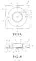
- FIGS. 1A and 1B are diagrams schematically illustrating a structure of a self-generating on/off switch according to a first embodiment of the present invention
- FIG. 1A is a plan view of the structure
- FIG. 1B is a side view of the structure.
- the self-generating on/off switch according to the present invention illustrated in FIGS. 1A and 1B employed as a switch for an on/off operation for working an appliance/electronic product that requires a corresponding standby power cut-off.
- the self-generating on/off switch according to the present invention distinctively includes a structure that self-generates power for a turning-on signal and a turning-on operation at the time of an "on" operation.
- the present invention self-generates power for operating the power switching unit at the self-generating on/off switch.
- a self-generating on/off switch 1 self-generates power with the mechanical movement of a first knob (a dial knob 11) by the turning-on operation of a user, and generates the turning-on signal with the power.
- the self-generating on/off switch 1 may include an on-switch module generating an "on” signal and an off-switch module generating an "off” signal, and may be implemented by, for example, a tube-shaped dial knob 11 that is installed on a plate 16 in a rotatable manner and including a hollow and a press knob 14 that is provided in the hollow of the dial knob 11 and that can be pressed.
- a plurality of permanent magnets 13 for power generation are installed with north poles and south poles alternately arranged in appropriate places, and a coil 8 for power generation is installed inside the press knob 14. Accordingly, when the dial knob 11 is rotated, the permanent magnets 13 arranged therein rotate about the press knob 14 as a rotation axis so that N poles and S poles are alternately changed, and therefore the current is generated in the coil 8 provided in the press knob 14. The generated current is generated through an input-output line 12 connected to the coil 8. Accordingly, the permanent magnets 13 installed in the dial knob 11 and the coil 8 provided in the press knob 14 are connected with each other to form a generation structure.
- the off-switch module that generates the "off" signal in the the self-generating on/off switch 1 may be implemented through the press knob 14 and the tact switch 15. That is, the operation of pressing the press knob 14 is to be provided with an operation for powering off the corresponding apparatus from the user.
- the tact switch 15 connected with the press knob 14 is provided to come into contact with the lower portion of the press knob 14. When the press knob 14 is pressed, contact points C1 and C2 of the tact switch 15 are connected, and when the press knob 14 is unpressed, the press knob 14 comes back to the original place by the power of a spring in the tact switch 15 so that contact points C1 and C2 of the tact switch 15 are separated.
- the the self-generating on/off switch 1 may be configured according to the first embodiment of the present invention as described above.
- the dial knob 11 may have a rotatable structure and also have a structure in which the entire dial knob 11 is pressed.
- a tact switch is installed below the dial knob so that an "off" signal is generated by the tact switch when the dial knob is pressed.
- the self-generating on/off switch 1 may have various structures according to the present invention.
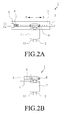
- FIGS. 2A and 2B are drawings schematically illustrating the structure of the self-generating on/off switch according to a second embodiment of the present invention.
- FIG. 2A is a plan view of the structure and
- FIG. 2B is a side view of the structure.
- the self-generating on/off switch 1 according to the second embodiment of the present invention self-generates power by the mechanical movement of the first knob (stick-shaped press knob 2) by a user performing a turning-on operation and generates the turning-on signal with the power.
- the self-generating on/off switch 1 includes a small generator 7 and a rotatable pinion gear 6 that is connected with a rotor of the small generator 7 and a stick-shaped press knob 2 having a rack gear structure connected with the pinion gear 6.
- the self-generating on/off switch 1 may include a supporting member 3 that supports and guides the movement of the stick-shaped press knob 2.
- the stick-shaped press knob 2 when the stick-shaped press knob 2 is pressed in the A direction, the pinion gear 6 engaged with the rack gear structure of the stick shaped knob 2 rotates to rotate the rotor of the generator 7 so that the power is generated.
- the stick-shaped press knob 2 includes a spring 4 for providing restoration force, so when the pressed stick-shaped press knob 2 is unpressed, the spring 4 moves back in the B direction so that the stick-shaped press knob 2 comes back to the original position.
- the power of the apparatus may be powered off (that is, the operation of the stick-shaped press knob may turn on the corresponding apparatus when the corresponding product is in an "off” state, and may turn off the corresponding product when the corresponding apparatus is in an "on” state).
- a photo-coupler 5 that generates an "off” signal, when the stick-shaped press knob 2 is pressed, may be provided. That is, when the stick-shaped press knob 2 is pressed, light generated from a light emitting device of the photo-coupler 5 is blocked by one end of the press knob 2 and the pressed spring 4 so that the light is not input to the light receiving element.
- FIG. 3 is a block diagram illustrating a circuit of corresponding units of the appliance/electronic product provided with the standby power cut-off apparatus according to the first embodiment of the present invention.
- the standby power shutoff device according to the first embodiment of the present invention basically includes: an on/off switching unit 27 that includes the self-generating on/off switch 1 as illustrated in FIGS.
- the self-generating on/off switch 1 employs the structure of the first embodiment illustrated in FIG. 1 , for example.
- the power unit 22 may be configured to be provided with 110 V or 220 V of commercial AC power and to generate, for example, 12 V or 5 V of power VCC and VP for operating the product.
- the power switching unit 26 may be implemented by the latching relay for powering on and off simply by a driving signal.
- the control unit 23 may be implemented by a microcomputer U1 in order to control the entire operation states, calculations, and determinations.
- the on/off switching unit 27 may only include the the self-generating on/off switch 1 as illustrated in FIGS. 1A, 1B , 2A, and 2B .
- the on/off switching unit 27 may include an AC-DC converter 21 for converting the generated AC electric power to DC electric power and the AC-DC converter 21 supply power VG for operating the the driving unit 24.
- the time delay unit 25 may be provided for delaying a signal output from the AC-DC converter 21 to provide the delayed signal to the driving unit 24 so that the driving unit 24 is turned on.
- the driving unit 24 may be implemented to have a structure connecting an "on" signal provided from the on/off switching unit 27 with first to fourth transistors (for example, NPN-type transistors) for performing switching by the control signal of the control unit 23.
- first to fourth transistors for example, NPN-type transistors
- the first and second transistors Q1 and Q2 of the driving unit 24 have a structure in which operating power VCC provided from the power unit 22 and operating power VG corresponding to the "on" signal provided from the on/off switching unit 27 is respectively provided from inputs (for example, collector terminals), an output (for example, an emitter terminal) of the second transistor Q2 is connected with the first terminal S of a solenoid of the power switching unit 26, and an output (the emitter terminal) of a first transistor Q1 is connected with the second terminal R of the solenoid.
- an input (a collector terminal) of a third transistor Q3 is connected to the first terminal S of the solenoid, an output (an emitter terminal) is connected to the ground terminal, an input (a collector terminal) of a fourth transistor Q4 is connected to the second terminal R of the solenoid, and an output (an emitter terminal) is connected to the ground terminal.
- the first and fourth transistor Q1 and Q4 are turned on, the current flows from the second terminal R to the first terminal S of the solenoid of the latching relay of the power switching unit 26 so that the solenoid is energized, contact points C3 and C4 of the latching relay come into contact with each other, and the power is supplied to the power unit 22.
- contact points C1 and C2 of the tact switch 15 come into contact with each other and the contact point C1 has a configuration in which the contact point C1 is connected with microcomputer input I1 of the control unit 23 and provided with power VCC for operating the corresponding product through a resistance R1, and the contact point C2 is connected to the ground terminal. Accordingly, the contact points C1 and C2 come into contact with each other, a signal in a low state is supplied to the microcomputer input I1 of the control unit 23.
- the signal in the low state by the photo-coupler 5 is configured to be supplied to the input I1 of the microcomputer U1.
- the control unit 23 may be configured so that an output 01 is output in a high state and applied to the base terminal of the second and third transistors Q2 and Q3 of the driving unit in order to cut off power supply.
- the control unit 23 is accordingly configured so that the second and third transistors Q2 and Q3 are turned on, the current flows from the first terminal S to the second terminal R of the solenoid of the latching relay of the power switching unit 26 so that the solenoid is energized, contact points C3 and C4 are separated, and the power supply to the power unit 22 is cut off.
- the dial knob 11 configured on the plate 16 illustrated in FIG. 1 is rotated in order to generate the initial electricity for turning on the power of the product, the permanent magnets 13 in the dial knob 11 rotate and N poles and S poles alternate, and the current flows in the coil 8 mounted in the press knob 14, thereby generating the electricity.
- the electricity generated in this way may be an alternating current.
- the alternating current is converted to the direct current by the AC-DC converter 21 as illustrated in FIG. 2 so that the driving power VG is supplied to the driving unit 24.
- the "on" signal is delayed by the time delay unit so that the "on” signal of the power is supplied to the driving unit 24 after a certain time.
- the "on" signal supplied to the driving unit 24 is applied to the base terminal of the first and fourth transistors Q1 and Q4 of the driving unit 24 in a high state and the first and fourth transistors Q1 and Q4 are turned on so that the current flows from the second terminal R to the first terminal S of the solenoid of the latching relay so that the solenoid is energized, contact points C3 and C4 of the latching relay come into contact with each other, and the power is supplied to the power unit 22.
- the power unit 22 If the power is supplied to the power unit 22, the power unit 22 generates and supplies the power required for the product. When the required power is supplied to the control unit 23, the control unit 23 starts to control and perform the function of the product.
- the stick-shaped press knob 2 illustrated in FIG. 2 when the stick-shaped press knob 2 illustrated in FIG. 2 is pressed in the A direction, the stick-shaped press knob 2 blocks the light transmitted by the photo-coupler 5 and the input I1 of the microcomputer U1 becomes a low state by the blocking of the light transmission.
- the microcomputer U1 determines to turn off the power and supplies the output 01 of the microcomputer U1 in the high state.
- the output 01 is applied to the base terminal of the second and third transistors Q2 and Q3 of the driving unit 24 so that the second and third transistors Q2 and Q3 are turned on. Accordingly, the current flows from the first terminal S to the second terminal R of the solenoid of the latching relay so that the solenoid is energized in an opposite state from the "on" state, and contact points C3 and C4 of the latching relay are separated to cut off the power supplied to the power unit 22, thereby completely cutting off the standby power.
- the present invention may embody the on/off switch and the standby power cut-off apparatus using the on/off switch, and accordingly perform the on/off switching operation and the standby power cut-off operation.
- the present invention is described above with specific embodiments, but various modifications may be possible without departing from the scope of the invention.
- the "on" signal generated from the on/off switching unit 27 is provided to the driving unit 24, and the driving unit 24 drives the power switching unit 26, but it may be possible that the "on" signal generated from the on/off switching unit 27 directly drives the power switching unit 26. With reference to FIG. 4 , this operation will be described in more detail.
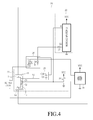
- FIG. 4 is a block diagram illustrating a circuit of the corresponding units in the appliance/electronic product provided with the standby power cut-off apparatus according to the second embodiment of the present invention.
- the configuration according to the second embodiment illustrated in FIG. 4 is mostly similar to the configuration of the first embodiment illustrated in FIG. 3 .
- the second embodiment has a structure in which the roles of the driving unit 24 and the power switching unit 26 in the configuration of the first embodiment illustrated in FIG. 2 are performed in a power switching unit 28 configured by photo-triac which is a structure of connecting the photo-coupler and triac in the second embodiment illustrated in FIG. 4 .
- photo-triac which is a structure of connecting the photo-coupler and triac in the second embodiment illustrated in FIG. 4 .
- the photo-coupler portion of the photo-triac functions as the driving unit
- the triac portion functions as the power switching unit.
- the second embodiment may have a structure in which the "on" signal (power) generated from an on/off switching unit 1 is supplied to a light emitting diode D8 of the photo-triac of the power switching unit 28, and the control signal output from the third output 03 of the microcomputer U1 of the control unit 23 is provided to the light emitting diode D8 of the photo-triac in common.
- the microcomputer U1 of the control unit 23 makes the third output 03 in the high state and supplies the third output 03 the light emitting diode D8 of the photo-triac so that the photo-triac is continuously in a turn-on state and the power supply to the power unit 22 is continued.
- the microcomputer U1 of the control unit 23 outputs the third output 03 in the low state so that the power of the light emitting diode D8 of the photo-triac is cut off and the light is emitted. Accordingly, the photo-triac is turned off, the main transmission lines T1 and T2 of the photo-triac are cut off, the power supplied to the power unit 22 is cut off, and the standby power becomes zero.
- the standby power cut-off apparatus using the photo-triac according to the second embodiment of the present invention is configured, and in this case, the on/off switching unit 27 may not be provided with the time delay unit 25, as provided in the first embodiment illustrated in FIG. 3 .
Landscapes
- Business, Economics & Management (AREA)
- Emergency Management (AREA)
- Engineering & Computer Science (AREA)
- Power Engineering (AREA)
- Keying Circuit Devices (AREA)
- Supply And Distribution Of Alternating Current (AREA)
- Television Receiver Circuits (AREA)
Applications Claiming Priority (2)
| Application Number | Priority Date | Filing Date | Title |
|---|---|---|---|
| KR20100055763 | 2010-06-14 | ||
| PCT/KR2011/004255 WO2011159066A2 (ko) | 2010-06-14 | 2011-06-10 | 온/오프 스위치 및 이를 이용한 대기전력 차단 장치 |
Publications (2)
| Publication Number | Publication Date |
|---|---|
| EP2582011A2 true EP2582011A2 (de) | 2013-04-17 |
| EP2582011A4 EP2582011A4 (de) | 2014-06-11 |
Family
ID=45348721
Family Applications (1)
| Application Number | Title | Priority Date | Filing Date |
|---|---|---|---|
| EP20110795932 Withdrawn EP2582011A4 (de) | 2010-06-14 | 2011-06-10 | Ein/aus-schalter und standby-ausschaltvorrichtung damit |
Country Status (6)
| Country | Link |
|---|---|
| US (1) | US9356468B2 (de) |
| EP (1) | EP2582011A4 (de) |
| JP (1) | JP5847172B2 (de) |
| KR (1) | KR101298186B1 (de) |
| CN (1) | CN102971936B (de) |
| WO (1) | WO2011159066A2 (de) |
Families Citing this family (15)
| Publication number | Priority date | Publication date | Assignee | Title |
|---|---|---|---|---|
| US8891251B2 (en) * | 2010-04-07 | 2014-11-18 | Apple Inc. | Method and apparatus for achieving zero AC-draw mode for a device |
| CN102971936B (zh) * | 2010-06-14 | 2016-03-16 | 金昌镐 | 通/断开关和使用所述通/断开关的待机功率关断设备 |
| KR101473890B1 (ko) * | 2012-04-09 | 2014-12-24 | 김창호 | 대기전력을 차단하는 기능을 갖는 전원시스템 |
| WO2015030459A1 (ko) * | 2013-08-26 | 2015-03-05 | Kim Chang-Ho | 대기전력 차단장치 |
| CN104516282A (zh) * | 2013-09-29 | 2015-04-15 | 上海本星电子科技有限公司 | 关机节能系统 |
| CN104698903B (zh) * | 2013-12-08 | 2019-10-22 | 宿州滋原科技咨询有限公司 | 一种电器待机启动装置及电视机与电脑电源 |
| KR101674635B1 (ko) * | 2014-03-27 | 2016-11-09 | 광운대학교 산학협력단 | 전기기계식 스위치와 반도체 트랜지스터가 융합된 능동형 다이오드 |
| CN104378565A (zh) * | 2014-11-07 | 2015-02-25 | 国网上海市电力公司 | 电视机电源彻底切断系统 |
| KR102236583B1 (ko) | 2014-12-05 | 2021-04-06 | 삼성전자주식회사 | 전자기기용 조그 다이얼 및 이를 구비한 전자기기 |
| JP6966905B2 (ja) * | 2017-09-15 | 2021-11-17 | 富士通コンポーネント株式会社 | 印刷装置 |
| US10503235B2 (en) | 2017-10-24 | 2019-12-10 | Hing S Tong | Wake from off state power system |
| KR102070670B1 (ko) * | 2018-10-04 | 2020-01-30 | 김병호 | 대기전력 차단 장치 |
| TWI682606B (zh) * | 2019-04-18 | 2020-01-11 | 緯創資通股份有限公司 | 具有遠端遙控自回覆斷電機制的電源產生裝置 |
| CN112962494B (zh) * | 2021-02-25 | 2022-04-15 | 解益君 | 一种赛道防护栏 |
| SE545243C2 (en) * | 2021-10-22 | 2023-06-07 | Assa Abloy Ab | Energy harvesting arrangement, access member device and access member system |
Family Cites Families (28)
| Publication number | Priority date | Publication date | Assignee | Title |
|---|---|---|---|---|
| US3904896A (en) * | 1970-06-30 | 1975-09-09 | Siemens Ag | Piezoelectric oscillator system |
| US4194482A (en) * | 1978-05-23 | 1980-03-25 | Mcculloch Corporation | Self generating ignition system |
| JPH0347221A (ja) | 1989-07-14 | 1991-02-28 | Tokyo Electric Co Ltd | 電気掃除機 |
| US5163844A (en) * | 1990-10-30 | 1992-11-17 | Texas Instruments Incorporated | Battery-free electronic teaching apparatus with keypad of piezo film switches |
| US5844516A (en) * | 1993-12-03 | 1998-12-01 | Oy Helvar | Method and apparatus for wireless remote control |
| JPH10164763A (ja) | 1996-12-03 | 1998-06-19 | Sony Corp | 発電機内蔵電子機器 |
| CA2236986A1 (en) | 1997-05-07 | 1998-11-07 | Mas-Hamilton Group | Electronic combination lock and capacitor charging circuit |
| FR2787254B1 (fr) | 1998-12-09 | 2001-01-26 | Gabriel Bouzaglo | Dispositif permettant de produire l'energie necessaire au fonctionnement d'un petit appareil electrique |
| JP3678075B2 (ja) | 1998-12-09 | 2005-08-03 | セイコーエプソン株式会社 | 電源装置およびその制御方法、携帯型電子機器、計時装置およびその制御方法 |
| JP2002078232A (ja) | 2000-08-29 | 2002-03-15 | Seiko Instruments Inc | 電子機器 |
| JP2002238152A (ja) | 2001-02-14 | 2002-08-23 | Sony Corp | 電源供給回路 |
| WO2002103880A1 (en) | 2001-06-15 | 2002-12-27 | Koninklijke Philips Electronics N.V. | Power supply for household appliance with standby mode and household appliance using said power supply |
| KR100477446B1 (ko) | 2002-08-30 | 2005-03-22 | 재단법인 포항산업과학연구원 | 가전기기의 대기전력 소모를 절감하는 절전기 |
| KR100456563B1 (ko) * | 2002-08-31 | 2004-11-10 | 현대자동차주식회사 | 로터리형 무접점 인포메이션 스위치 |
| CN2614757Y (zh) | 2003-05-08 | 2004-05-12 | 陈定兴 | 磁力发电发光玩具 |
| JP2005115889A (ja) | 2003-10-06 | 2005-04-28 | Toshiyuki Amino | 回転キー式入力装置 |
| US20060158485A1 (en) | 2005-01-18 | 2006-07-20 | Hill Gregory S | Power switch system |
| GB0706401D0 (en) | 2007-04-04 | 2007-05-09 | Universal Concepts Ltd | Power saving means |
| US20090031147A1 (en) * | 2007-07-24 | 2009-01-29 | Infineon Technologies Ag | Apparatus for waking up a device |
| JP5098620B2 (ja) | 2007-12-13 | 2012-12-12 | 横河電機株式会社 | 電源スイッチ回路 |
| KR101017184B1 (ko) | 2008-06-13 | 2011-02-25 | 김동룡 | 대기전력 차단용 멀티탭 콘센트 |
| KR100999426B1 (ko) | 2008-06-16 | 2010-12-13 | 김용석 | 대기전력 차단장치 |
| JP2010029515A (ja) | 2008-07-30 | 2010-02-12 | Juki Corp | 遊技機用ボタンユニット |
| KR20100057457A (ko) | 2008-11-21 | 2010-05-31 | 웅진코웨이주식회사 | 자가발전을 이용한 대기전력 제로화 시스템 및 방법 |
| KR100945210B1 (ko) * | 2009-03-05 | 2010-03-03 | 김창호 | 대기전력 차단 장치 및 그 제어 방법 |
| EP2378015B1 (de) * | 2010-04-15 | 2017-05-10 | Woongjin Coway Co., Ltd. | Verfahren zum Steuern eines selbsterzeugenden Bidet |
| CN102971936B (zh) * | 2010-06-14 | 2016-03-16 | 金昌镐 | 通/断开关和使用所述通/断开关的待机功率关断设备 |
| US9064660B2 (en) * | 2012-03-22 | 2015-06-23 | Technology Logic International Limited | Remote controlled interactive power switch |
-
2011
- 2011-06-10 CN CN201180029427.9A patent/CN102971936B/zh active Active
- 2011-06-10 US US13/704,144 patent/US9356468B2/en not_active Expired - Fee Related
- 2011-06-10 JP JP2013515260A patent/JP5847172B2/ja active Active
- 2011-06-10 KR KR1020110055944A patent/KR101298186B1/ko active Active
- 2011-06-10 EP EP20110795932 patent/EP2582011A4/de not_active Withdrawn
- 2011-06-10 WO PCT/KR2011/004255 patent/WO2011159066A2/ko not_active Ceased
Also Published As
| Publication number | Publication date |
|---|---|
| KR101298186B1 (ko) | 2013-08-20 |
| US20130088097A1 (en) | 2013-04-11 |
| CN102971936B (zh) | 2016-03-16 |
| WO2011159066A3 (ko) | 2012-04-19 |
| JP5847172B2 (ja) | 2016-01-20 |
| US9356468B2 (en) | 2016-05-31 |
| JP2013530671A (ja) | 2013-07-25 |
| KR20110136715A (ko) | 2011-12-21 |
| EP2582011A4 (de) | 2014-06-11 |
| WO2011159066A2 (ko) | 2011-12-22 |
| CN102971936A (zh) | 2013-03-13 |
Similar Documents
| Publication | Publication Date | Title |
|---|---|---|
| US9356468B2 (en) | On/off switch and standby power shutoff device using same | |
| JP5318196B2 (ja) | 待機電力遮断装置及びその制御方法 | |
| DK1073544T3 (da) | Fremgangsmåde til dataoverføring mellem et el-miniapparat og et elektrisk ekstraapparat, som kan forbindes med dette, samt tilsvarende udformede apparater | |
| DK1112010T3 (da) | Reguleringsanordning til omstilling af et møbel | |
| EP1223752A3 (de) | Automatischer Netzschalter | |
| CN101334644A (zh) | 一种手动开机自动关机后零功耗待机的解决方案 | |
| DE50306812D1 (de) | Elektromotorisch betriebenes Küchengerät | |
| EP1376814A3 (de) | Stromversorgungssteuerschaltung | |
| GB1604498A (en) | Time counter | |
| US12546045B2 (en) | Household appliance particularly suitable for use in a hybrid electrical power system and hybrid electrical power system comprising the same | |
| CN210431278U (zh) | 一种带逆变控制的马达驱动集成电路 | |
| WO2013098015A3 (en) | A household appliance protected from mains over voltage | |
| CN2450805Y (zh) | 电源集成插座的开关装置 | |
| CN206180992U (zh) | 一种无耗能电子开关 | |
| KR20170042078A (ko) | 스마트 멀티탭 | |
| CN216773714U (zh) | 一种电器工程安装配电用工业插座 | |
| KR20150016655A (ko) | 반도체 전원동기형 솔레노이드 직선운동을 이용하여 모터구동을 대체한 소비전력 절감형 기계식 타이머 | |
| KR200235472Y1 (ko) | 전원 공급용 콘센트 | |
| CN2353038Y (zh) | 多功能电子定时开关 | |
| WO2003005544A3 (en) | A control circuit for an inductive device | |
| KR200261372Y1 (ko) | 전력조절용 타임 스위치 | |
| WO2008038125A3 (en) | Electronic starter device for an electric motor, in particular for a compressor of a refrigerating circuit of an electric household appliance | |
| CN203930398U (zh) | 一种多极电路切换开关 | |
| CN101958042A (zh) | 手握式充电遥控器 | |
| CN2911925Y (zh) | 一种家用开关面板 |
Legal Events
| Date | Code | Title | Description |
|---|---|---|---|
| PUAI | Public reference made under article 153(3) epc to a published international application that has entered the european phase |
Free format text: ORIGINAL CODE: 0009012 |
|
| 17P | Request for examination filed |
Effective date: 20130110 |
|
| AK | Designated contracting states |
Kind code of ref document: A2 Designated state(s): AL AT BE BG CH CY CZ DE DK EE ES FI FR GB GR HR HU IE IS IT LI LT LU LV MC MK MT NL NO PL PT RO RS SE SI SK SM TR |
|
| DAX | Request for extension of the european patent (deleted) | ||
| A4 | Supplementary search report drawn up and despatched |
Effective date: 20140512 |
|
| RIC1 | Information provided on ipc code assigned before grant |
Ipc: H02J 9/00 20060101AFI20140506BHEP Ipc: H01R 13/70 20060101ALI20140506BHEP |
|
| STAA | Information on the status of an ep patent application or granted ep patent |
Free format text: STATUS: THE APPLICATION HAS BEEN WITHDRAWN |
|
| 18W | Application withdrawn |
Effective date: 20150618 |