EP2580490B1 - Seilendverbindung - Google Patents
Seilendverbindung Download PDFInfo
- Publication number
- EP2580490B1 EP2580490B1 EP11729904.0A EP11729904A EP2580490B1 EP 2580490 B1 EP2580490 B1 EP 2580490B1 EP 11729904 A EP11729904 A EP 11729904A EP 2580490 B1 EP2580490 B1 EP 2580490B1
- Authority
- EP
- European Patent Office
- Prior art keywords
- pin
- guide
- connecting means
- means according
- pipe section
- Prior art date
- Legal status (The legal status is an assumption and is not a legal conclusion. Google has not performed a legal analysis and makes no representation as to the accuracy of the status listed.)
- Not-in-force
Links
Images



Classifications
-
- F—MECHANICAL ENGINEERING; LIGHTING; HEATING; WEAPONS; BLASTING
- F16—ENGINEERING ELEMENTS AND UNITS; GENERAL MEASURES FOR PRODUCING AND MAINTAINING EFFECTIVE FUNCTIONING OF MACHINES OR INSTALLATIONS; THERMAL INSULATION IN GENERAL
- F16G—BELTS, CABLES, OR ROPES, PREDOMINANTLY USED FOR DRIVING PURPOSES; CHAINS; FITTINGS PREDOMINANTLY USED THEREFOR
- F16G11/00—Means for fastening cables or ropes to one another or to other objects; Caps or sleeves for fixing on cables or ropes
-
- A—HUMAN NECESSITIES
- A63—SPORTS; GAMES; AMUSEMENTS
- A63B—APPARATUS FOR PHYSICAL TRAINING, GYMNASTICS, SWIMMING, CLIMBING, OR FENCING; BALL GAMES; TRAINING EQUIPMENT
- A63B29/00—Apparatus for mountaineering
- A63B29/02—Mountain guy-ropes or accessories, e.g. avalanche ropes; Means for indicating the location of accidentally buried, e.g. snow-buried, persons
-
- B—PERFORMING OPERATIONS; TRANSPORTING
- B63—SHIPS OR OTHER WATERBORNE VESSELS; RELATED EQUIPMENT
- B63B—SHIPS OR OTHER WATERBORNE VESSELS; EQUIPMENT FOR SHIPPING
- B63B21/00—Tying-up; Shifting, towing, or pushing equipment; Anchoring
- B63B21/04—Fastening or guiding equipment for chains, ropes, hawsers, or the like
- B63B21/08—Clamping devices
-
- F—MECHANICAL ENGINEERING; LIGHTING; HEATING; WEAPONS; BLASTING
- F16—ENGINEERING ELEMENTS AND UNITS; GENERAL MEASURES FOR PRODUCING AND MAINTAINING EFFECTIVE FUNCTIONING OF MACHINES OR INSTALLATIONS; THERMAL INSULATION IN GENERAL
- F16G—BELTS, CABLES, OR ROPES, PREDOMINANTLY USED FOR DRIVING PURPOSES; CHAINS; FITTINGS PREDOMINANTLY USED THEREFOR
- F16G11/00—Means for fastening cables or ropes to one another or to other objects; Caps or sleeves for fixing on cables or ropes
- F16G11/14—Devices or coupling-pieces designed for easy formation of adjustable loops, e.g. choker hooks; Hooks or eyes with integral parts designed to facilitate quick attachment to cables or ropes at any point, e.g. by forming loops
-
- A—HUMAN NECESSITIES
- A63—SPORTS; GAMES; AMUSEMENTS
- A63B—APPARATUS FOR PHYSICAL TRAINING, GYMNASTICS, SWIMMING, CLIMBING, OR FENCING; BALL GAMES; TRAINING EQUIPMENT
- A63B29/00—Apparatus for mountaineering
- A63B29/02—Mountain guy-ropes or accessories, e.g. avalanche ropes; Means for indicating the location of accidentally buried, e.g. snow-buried, persons
- A63B29/028—Ropes specially adapted for mountaineering
Definitions
- the invention relates to a connecting means for an elongated limp element.
- a rescue device according to the preamble of claim 1 is known with a variable in length loop and a circular attachment piece with two parallel cable bushings. A rope is guided through the two cable bushings while forming the loop and secured with a knot outside the second cable bushing.
- a load-adjustable, breakable safety device is disclosed.
- a safety point which is designed in the form of a hole in the device, between two security points lying weakness zones are enclosed, whereby the overall stability of the safety device can be changed.
- the DE 199 06 120 A1 describes a loop device that makes it possible to adjust the size of a rope loop steplessly.
- a rope end is fastened with a node to an eyelet, while the rope is continued as a loop via a clamping part.
- the clamping part With the help of the clamping part, the length of the loop can be adjusted continuously.
- the JP 612 668 14 A discloses a cable end connection in which the end of a rope can be pivotally mounted on an arm.
- the arrangement is made via a connecting piece, which has a slot and a recess into which a thickening of the end of the rope is inserted, which engages behind the slot.
- a fastener for a cable end on a rod which has a hook arranged pivotably on a guide.
- a disadvantage of the rope end connections known from the prior art is, in particular, that the knot of the rope end section can be difficult to loosen again after loading.
- the connecting means according to the invention for and with an elongate limp element is characterized by its simplicity and yet existing security.
- the connecting means comprises a guide with a guide input and a guide output for pulling an end portion of the elongate limp element in the pull-through direction.
- an elongate pin is arranged with a pin longitudinal direction in the direction of pull-through.
- the pin can be designed as a solid profile, but also as a hollow profile.
- the lanyard can be used in various areas, such as the sail area, the climbing area and the like.
- the elongated pliable element is secured against loosening from the connecting means in two ways.
- the pin has a free portion to which the end portion is tied.
- the festgeknotete at the free portion of the pin end portion of the elongate limp element is thus secured against slipping against the pull-through direction of the guide.
- the diameter of the guide is chosen smaller than a knot diameter.
- the end portion is secured by the knot on the free portion of the pin against slipping out, on the other hand, the knot after load is particularly easy to solve again, because it is knotted around the pin.
- the node can be pulled down by the pin after the use of the connecting means, and the free space within the node resulting from the extraction of the pin makes it particularly easy to release the node.
- At least one fastening means is arranged on the connecting means, with which the connecting means can be attached to a device.
- the connecting means may be attached, integrated or arranged, for example, on a climbing harness, climbing harness, a climbing clamp or a carabiner.
- the connection between connecting means and the device is preferably detachable and has a securing mechanism which secures against self-loosening.
- the attachment means may be provided directly on the guide or on the pin.
- connection can be formed by a fastening means designed as an insertion part and a device arranged on the insertion device for the insertion part.
- the insertion part is preferably formed as a cuboid metal plate.
- the fastening means comprises a latching mechanism.
- latching mechanism and latching are widely understood here and in the following.
- the fastener may be formed as a latching mechanism at the tip of the pin.
- the guide comprises a pipe section.
- the pipe section has a pipe inlet and a pipe outlet. Through the pipe inlet, the end portion of the element in the pipe section is inserted and pulled out of the pipe outlet.
- the pipe section is formed hollow throughout in the pull-through direction.
- the pin is fastened to the outside of the pipe section, preferably welded or soldered, and the longitudinal direction of the pin is aligned substantially parallel to the longitudinal direction of the pipe section.
- the free end of the pin is arranged at an angle to the pull-through direction or that the free end is curved and preferably curved away from the guide output.
- At least one further guide is provided on the one guide, and the at least one further guide is positionally stable even under tensile and compressive loads against the one guide and mounted on the one guide.
- the guides may preferably be welded or soldered together. However, it is also conceivable that the guides are detachably connected to each other via plug-in mechanisms.
- the further guide can also have another pin arranged on it. The pin and the further pin can protrude in the same or in the opposite direction from the connecting means.
- the fastening means is designed as a holding plate, and the guides are fixed to the holding plate also under tensile and compressive load position stable.
- a safety means is provided at the free end of the pin.
- the safety means is preferably designed as a pivotable safety arm, which is 29ränkbar after knotting the end portion at the free portion of the pin, so that a longitudinal direction of the safety arm is arranged substantially transversely, preferably perpendicular to the longitudinal direction of the pin. It But it is also conceivable to form the safety means as insertable into the pin pin or screw
- Seilend investigating 1 has a designed as a pipe section 10 cable guide.
- the pipe section 10 has a constant cross-section along its longitudinal direction L. Both an inner and an outer diameter of the pipe section 10 are constant along the longitudinal direction L over its entire longitudinal extent.
- the pipe section 10 is formed here of metal. It may be for the pipe section and other components of the cable end connections, other materials such as solid plastics u. ⁇ . be used.
- Attached to the cable end connection 1 along an outer side of the pipe section 10 is preferably a fastening means which is preferably in the form of a cuboid, flat metal plate 11, even under pressure and toughening, preferably welded thereto.
- a fastening means which is preferably in the form of a cuboid, flat metal plate 11, even under pressure and toughening, preferably welded thereto.
- On one of the metal plate 11 opposite outside of the pipe section 10 is also aligned in the longitudinal direction L elongated pin 12 is attached.
- the pin 12 is formed as an elongate solid profile, preferably as a rod-shaped solid metal pin.
- the pin 12 is welded on the outside of the pipe section 10 here.
- the longitudinal direction L of the pin 12 defined by the longitudinal extent of the pin 12 extends parallel to the longitudinal direction L of the pipe section 10.
- the pipe section 10 has a pipe section inlet 13 and a pipe section outlet 14.
- the pipe section entrance 13 is in Fig. 1 above
- the pipe section exit 14 is in Fig. 1 at the bottom of the pipe section 10 in Fig. 1 intended.
- a cable end section 20 can be pulled through the pipe section 10 inside and out of the pipe section exit 14 via the pipe section inlet 13.
- the pull-through direction of the cable end section 20 extends in the longitudinal direction L.
- the pin 12 may be conical, with the cone tip directed away from the pipe section exit 14. This facilitates the removal of the loaded node.
- the pin 12 is welded to a fixed portion 16 with the pipe section 10 and an adjacent free portion 17 is beyond the pipe section output beyond a length of the free portion 17 from.
- the free portion 17 is directed away from the pipe section output 14 from the pipe section 10 from. It is aligned along a surface normal of an opening cross-section of the pipe section exit 14.
- the longitudinal direction L of the pin 12, the pull-through direction of the cable end portion 20 and the longitudinal direction L of the pipe section 10 are in the cable end connection according to Fig. 1 aligned parallel to each other. Both pin 12 and metal plate 11 are connected under tensile and compressive loads fixed position with the pipe section 10.
- the rope end connection should be able to carry a certain load in the climbing area of at least 1.5 t, in order to meet the required breaking loads of the respective field of application.
- Fig. 2 the cable end connection is shown with rope end section 20 pulled through tube section 10.
- the continuous rope end portion 20 is knotted in the direction of pull the tube section outlet 14 trailing around the free portion 17 of the pin 12 around.
- the rope end portion 20 is on the in Fig. 2 way shown securely connected to the cable end connection and secured against slipping out of the pipe section 10 against the pull-through direction.
- the rope end portion 20 can not slip out of the cable end connection, because the rope end portion 20 is knotted over the free portion 17 of the pin 12, for another, the rope end portion, even if the node would slip off the pin 12, could not slip through the pipe section 10, because the node would safely prevent slipping out through the pipe section 10 against the pull-through direction.
- the diameter of the cable end section 20 is adapted to the inner diameter of the pipe section 10.
- the pipe section 10 has a constant along the entire longitudinal direction circular free inner cross section with a constant inner diameter.
- the walls of the tube section 10 are formed in the longitudinal direction L and along the circumference of substantially uniform thickness.
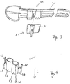
- Fig. 3 shows the cable end connection 1 of Figures 1 and 2 in cooperation with a permanently sewn with a harness 31 plug-in device 30.
- the in Fig. 1 and Fig. 2 shown Seilendtagen 1 is particularly suitable as part of a climbing harness.
- a climbing harness can be used when climbing mountains, especially when tree climbing in the context of tree care.
- the insertion device 30 is dimensioned for receiving the metal plate 11 of the cable end connection 1.
- the insertion device 30 is, based on the position in which the wearer of the climbing harness 31 has strapped the belt around his stomach, at the feet open and closed to the head.
- the cable end connection can therefore be inserted from the direction of the wearer's feet towards the head into the insertion device 30.
- the rope end connection 1 is secured with a (not shown) locking mechanism in the insertion against slipping out.
- Fig. 4 shows a second embodiment of the cable end connection 1 according to the invention there are four pipe sections 41, 42, 43, 44 positionally connected to each other under tensile and compressive load, preferably welded.
- Two middle pipe sections 42, 43 have a longer equal longitudinal extent in the longitudinal direction L, while two outer pipe sections 41, 44 shorter than the two middle longer pipe sections 42, 43 are formed.
- One of the two middle pipe sections 42 has no pin, the other middle pipe section 43 has a longer pin 46.
- the two outer shorter tube sections 41, 44 each have a shorter pin 47, 48.
- the longer pin 46 and the two shorter pins 47, 48 are in the opposite direction of the cable end connection 1 from.
- the rope end connection 1 in Fig. 4 is intended to pull the cable end portion 20 through the middle longer pipe section 43 with pin 46 from top to bottom through the cable end connection 1, while the two shorter outer pipe sections 41, 44 are intended to other Seilendab songs in Fig. 4 pull through from bottom to top.
- the cable end portions of each of the three cables may be securely tied to the respective pin 46, 47, 48 provided at the respective pipe section exit with the respective associated free portion of the pins 46, 47, 48.
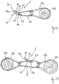
- Fig. 5a shows a counter-rotating double rope end connection 2 according to the invention with two mutually parallel pipe sections 51, 52, each with a pipe section input 53, 55 and a pipe section output 54, 56, on each of which a pin 57, 57a positionally fixed under tensile and compressive load is arranged.
- the opposite double rope end connection 2 is in Fig. 5a for the formation of an eye connection and in Fig. 5b used to form an endless connection.
- a first application of the double rope end connection 2 is shown, in which a loop 59a is placed with two end loops around a trunk 58a. Through both juxtaposed end loops of a loop 59a a rope 21 is guided.
- the cable 21 is knotted at one of its rope end portion 20 spaced portion through the first pipe section 51 and at the zu simplify pipe section output 54 at the associated pin 57 and passed thereafter in the direction of the cable end portion 20 through the two loops of a loop 59a.
- the cable end section 20 is then guided through the second pipe section 52 in opposite directions to the first pipe section 51 and knotted at the associated pipe section exit 56 to the associated pin 57 a.
- Augthetic Augthetic
- Fig. 5a intended double rope end connection 2 is used in the tree care area in particular for crown protection. In the stability due to, for example, strong winds damaged treetops can be secured with this double rope end connection 2.
- This in Fig. 5a Left open end of the rope 21 is for example connected to a ground anchor.
- Fig. 5b shows a second embodiment of the opposite double rope end connection 2 of Fig. 5a , It is in contrast to Fig. 5a no eye connection, but an endless connection between two Stämmlingen 58a, 58b formed.
- Fig. 5b first shows how in Fig. 5a , a first stocking 58a held by a first loop 59a provided with two end loops, and a second stocking 58b held by a second stocking 58b, which is the same as the first substantially identical, also provided with two loops 59b.
- Fig. 5a is the rope with its two end portions 20, 20a through the respective pipe section 51, 52 of the opposite direction extending double rope end connection 2 and thereby forms an endless connection.
- the cable end section 20 is guided through the second pipe section 52 and knotted to the associated pin 58, the other cable end section 20 a is guided through the first pipe section 51 and knotted to the associated pin 57.
- Fig. 6 shows a Gurtendharm 60, which is formed very similar to the cable end connection 1.
- the Gurtendharm 60 has a belt guide 61 with a rectangular cross-section perpendicular to the belt longitudinal direction opening cross-section, on the larger outer side of a metal plate 11 is arranged fixed in position. The metal plate 11 can be hooked to a counterpart.
- the rectangular in cross-section belt guide 61 also has a Gurt Resultsseingang 62 and a Gurt Entrysausgang 63 and arranged on Gurt Entrysausgang 63, facing away from him pin 64. At this Gurtendabêt 65 is knotted.
- Fig. 7 is a throwing hook 70 shown with a curved, compared to Fig. 1 longer trained pipe section 71, through which a rope end portion 20 is guided, which is knotted at a provided on the pipe section output 14 pin 12.
- the in Fig. 7 shown throwing hooks 70 can also be used in the field of tree care.
- Rope end connections 80, 90 are described which are integrated into a device.
- the cable end connection 80 is integrated in the handle of a cable clamp 81 and in Fig. 9 in a Karabinerbügel 91.
- the pin 12 is arranged in both cases, within the material encircling eye, and the pipe section 10 is passed transversely through the material.
- double rope end connection 2 comprises a pipe section 10 provided in the tube longitudinal direction L at the two pipe ends two pipe section entrances 13, 13a.
- two openings are introduced, which are formed as pipe section outputs 14, 14a.
- a pin 12, 12a is attached next to each of the pipe section exits, to each of which a cable section end 20, 20a is firmly knotted.
- the two cable section ends 20, 20a may be associated with the same cable or different cables.
- the pin longitudinal direction L and the longitudinal direction of the tube section 10 are transversely, preferably perpendicular to each other.
Landscapes
- Engineering & Computer Science (AREA)
- General Engineering & Computer Science (AREA)
- Mechanical Engineering (AREA)
- Health & Medical Sciences (AREA)
- Pulmonology (AREA)
- General Health & Medical Sciences (AREA)
- Physical Education & Sports Medicine (AREA)
- Chemical & Material Sciences (AREA)
- Combustion & Propulsion (AREA)
- Ocean & Marine Engineering (AREA)
- Emergency Lowering Means (AREA)
Description
- Die Erfindung betrifft ein Verbindungsmittel für ein längliches biegeschlaffes Element.
- Unter Seilendverbindungen werden hier Einrichtungen verstanden, an denen ein Seilendabschnitt eines Seils verknotet werden kann.
- Aus der
US 4,661,077 ist eine Rettungseinrichtung gemäß dem Oberbegriff des Anspruchs 1 bekannt mit einer in der Länge veränderbaren Schlaufe und einem kreisrunden Befestigungsstück mit zwei parallelen Seildurchführungen. Ein Seil wird unter Ausbildung der Schlaufe durch beide Seildurchführungen hindurch geführt und außerhalb der zweiten Seildurchführung mit einem Knoten gesichert. - In der
DE 410 5 667 A1 ist eine lasteinstellbare, brechbare Sicherheitseinrichtung offenbart. Je nach Wahl eines Sicherheitspunktes, der in Form eines Loches in der Einrichtung ausgebildet ist, werden zwischen zwei der Sicherheitspunkte liegende Schwächezonen umschlossen, wodurch sich die gesamte Stabilität der Sicherheitseinrichtung verändern lässt. - Die
DE 199 06 120 A1 beschreibt eine Schlaufenvorrichtung, die es ermöglicht, die Größe einer Seilschlaufe stufenlos zu verstellen. Dazu ist ein Seilende mit einem Knoten an einer Öse befestigt, während das Seil als Schlaufe über ein Klemmteil weitergeführt ist. Mit Hilfe des Klemmteils kann die Länge der Schlaufe stufenlos eingestellt werden. - Aus der
DE 231 267 A1 sind Endabschlüsse, Litzen und Seile bekannt. Der Endabschluss ist dabei auf ein Drahtseil aufgepresst oder aufgeschrumpft und greift in das Seil ein. Der Endabschluss weist einen Kragen mit wenigstens einer Lagerfläche auf, mit deren Hilfe das Seilende an einem Gegenstück befestigt werden kann. - Die
JP 612 668 14 A - Aus der
US 1,807,314 ist ein Kabelverbinder bekannt, an dem ein Kabelende befestigt werden kann und der mittels eines Auges an einem Stift befestigt werden kann. - Aus der
US 1,461,498 ist ein Befestigungsmittel für ein Seilende an einem Stab bekannt, das einen an einer Führung schwenkbar angeordneten Haken aufweist. - Nachteilig an den aus dem Stand der Technik bekannten Seilendverbindungen ist insbesondere, dass sich der Knoten des Seilendabschnitts nach Belastung schwer wieder lösen lässt.
- Es ist Aufgabe der vorliegenden Erfindung, ein Verbindungsmittel für ein längliches biegeschlaffes Element zur Verfügung zu stellen, an dem ein Endabschnitt des Elementes sicher verknotet werden kann und das dennoch ein leichtes Lösen eines Knotens ermöglicht.
- Die Aufgabe wird durch ein Verbindungsmittel mit den Merkmalen des Anspruchs 1 gelöst.
- Das erfindungsgemäße Verbindungsmittel für und mit einem länglichen biegeschlaffen Element zeichnet sich durch seine Einfachheit und dennoch vorhandene Sicherheit aus. Das Verbindungsmittel umfasst eine Führung mit einem Führungseingang und einem Führungsausgang zum Durchziehen eines Endabschnittes des länglichen biegeschlaffen Elementes in Durchziehrichtung. An dem Führungsausgang ist ein länglicher Pin angeordnet mit einer in Durchziehrichtung ausgerichteten Pin-Längsrichtung. Der Pin kann als ein Vollprofil, aber auch als Hohlprofil ausgebildet sein.
- Das Verbindungsmittel kann in verschiedenen Bereichen eingesetzt werden, wie dem Segelbereich, dem Kletterbereich u.a.
- Das längliche biegeschlaffe Element ist auf zwei Weisen vor dem Lösen vom Verbindungsmittel gesichert. Der Pin weist einen freien Abschnitt auf, an dem der Endabschnitt festgeknotet ist. Der am freien Abschnitt des Pins festgeknotete Endabschnitt des länglichen biegeschlaffen Elementes ist gegen Durchrutschen entgegen der Durchziehrichtung aus der Führung somit gesichert.
- Vorzugsweise ist der Durchmesser der Führung kleiner als ein Knotendurchmesser gewählt. Dadurch rutscht der vom Pin zufällig abgezogene Knoten dennoch nicht durch die Führung hindurch.
- Unter einem länglichen biegeschlaffen Element werden Seile, Gurte, Bänder usw. verstanden.
- Zum einen ist der Endabschnitt durch die Verknotung am freien Abschnitt des Pins gegen Herausrutschen gesichert, zum anderen ist der Knoten nach Belastung besonders leicht wieder lösbar, da er um den Pin herum geknotet ist. Der Knoten kann nach dem Gebrauch des Verbindungsmittels vom Pin heruntergezogen werden, und durch den sich durch das Herausziehen des Pins ergebenden Freiraum innerhalb des Knotens lässt sich der Knoten besonders leicht wieder lösen.
- Vorzugsweise ist an dem Verbindungsmittel wenigstens ein Befestigungsmittel angeordnet, mit dem das Verbindungsmittel an einer Vorrichtung befestigt werden kann. Das Verbindungsmittel kann beispielsweise an einem Klettergurt, Klettergeschirr, einer Steigklemme oder einem Karabiner befestigt, integriert oder angeordnet sein. Die Verbindung zwischen Verbindungsmittel und der Vorrichtung ist vorzugsweise lösbar und weist einen Sicherungsmechanismus auf, der gegen selbsttätiges Lösen sichert.
- Das Befestigungsmittel kann direkt an der Führung oder am Pin vorgesehen sein.
- Die Verbindung kann durch ein als Einschubteil ausgebildetes Befestigungsmittel und eine an der Vorrichtung angeordnete Einschubvorrichtung für das Einschubteil ausgebildet sein. Das Einschubteil ist vorzugsweise als quaderförmige Metallplatte ausgebildet.
- Günstigerweise umfasst das Befestigungsmittel einen Einklinkmechanismus. Die Begriffe Einklinkmechanismus sowie Einklinken werden hier und im Weiteren weit verstanden. Es sind davon auch Steck- und Klickmechanismen u. Ä. umfasst.
- Wenn das Befestigungsmittel am Pin vorgesehen ist, kann es als Einklinkmechanismus an der Spitze des Pins ausgebildet sein.
- Günstigerweise umfasst die Führung einen Rohrabschnitt. Der Rohrabschnitt weist einen Rohreingang und einen Rohrausgang auf. Durch den Rohreingang ist der Endabschnitt des Elementes in den Rohrabschnitt einführbar und aus dem Rohrausgang herausziehbar. Der Rohrabschnitt ist in Durchziehrichtung durchgängig hohl ausgebildet.
- In einer besonders bevorzugten Ausführungsform der Erfindung ist der Pin außen am Rohrabschnitt befestigt, vorzugsweise festgeschweißt oder gelötet, und die Längsrichtung des Pins ist im Wesentlichen parallel zur Längsrichtung des Rohrabschnitts ausgerichtet. Es ist jedoch auch denkbar, dass das freie Ende des Pins in einem Winkel zur Durchziehrichtung angeordnet ist oder dass das freie Ende gekrümmt ist und sich vorzugsweise vom Führungsausgang wegkrümmt.
- In einer Weiterbildung der Erfindung ist wenigstens eine weitere Führung an der einen Führung vorgesehen, und die wenigstens eine weitere Führung ist auch unter Zug- und Druckbelastungen posistionsstabil gegenüber der einen Führung und an der einen Führung montiert. Die Führungen können vorzugsweise miteinander verschweißt oder verlötet sein. Es ist jedoch auch denkbar, dass die Führungen über Steckmechanismen miteinander lösbar verbunden sind. Die weitere Führung kann auch einen weiteren an ihr angeordneten Pin aufweisen. Der Pin und der weitere Pin können in gleicher oder auch entgegengesetzter Richtung von dem Verbindungsmittel abstehen.
- Günstigerweise ist das Befestigungsmittel als Halteplatte ausgebildet, und die Führungen sind an der Halteplatte ebenfalls unter Zug- und Druckbelastung positionsstabil befestigt.
- In einer besonders sicheren Form des Verbindungsmittels ist am freien Ende des Pins ein Sicherheitsmittel vorgesehen. Das Sicherheitsmittel ist vorzugsweise als schwenkbarer Sicherheitsarm ausgebildet, der nach dem Verknoten des Endabschnitts am freien Abschnitt des Pins verschränkbar ist, so dass eine Längsrichtung des Sicherheitsarms im Wesentlichen quer, vorzugsweise senkrecht zur Längsrichtung des Pins angeordnet ist. Es ist aber auch denkbar, das Sicherheitsmittel als in den Pin einsteckbaren Stift oder Schraube auszubilden
- Die Erfindung wird anhand von acht Ausführungsbeispielen in zwölf Figuren beschrieben.
-
- Fig. 1
- eine erste Ausführungsform einer Seilendverbindung mit einer Seilführung,
- Fig. 2
- die erste Ausführungsform gemäß
Fig. 1 mit angeknotetem Seilendabschnitt, - Fig. 3
- die Seilendverbindung gemäß
Fig. 1 mit Schiebehalterung an einem Gürtel, - Fig. 4
- eine Seilendverbindung in einer zweiten Ausführungsform mit vier Seilführungen,
- Fig. 5a
- eine erfindungsgemäße Augverbindung für einen Baumstamm,
- Fig. 5b
- eine erfindungsgemäße Endlosverbindung für zwei Baumstämme,
- Fig. 6
- eine erfindungsgemäße Gurtendverbindung,
- Fig. 7
- einen erfindungsgemäßen Wurfhaken,
- Fig. 8
- eine erfindungsgemäße Seilklemme mit integrierter Seilendverbindung,
- Fig. 9
- einen erfindungsgemäßen Karabiner mit integrierter Seilendverbindung,
- Fig. 10
- eine zweifache Seilendverbindung.
- Die in
Fig. 1 dargestellte Seilendverbindung 1 weist eine als Rohrabschnitt 10 ausgebildete Seilführung auf. Der Rohrabschnitt 10 weist einen gleichbleibenden Querschnitt entlang seiner Längsrichtung L auf. Sowohl ein Innen- als auch ein Außendurchmesser des Rohrabschnitts 10 sind entlang der Längsrichtung L über seine gesamte Längsausdehnung konstant. Der Rohrabschnitt 10 ist hier aus Metall ausgebildet. Es können für den Rohrabschnitt und andere Bauteile der Seilendverbindungen auch andere Materialien wie feste Kunststoffe u. Ä. verwendet werden. - An der Seilendverbindung 1 ist entlang einer Außenseite des Rohrabschnitts 10 ein vorzugsweise als quaderförmige, flache Metallplatte 11 ausgebildetes Befestigungsmittel auch unter Druck- und Zugebelastung positionsfest befestigt, vorzugsweise angeschweißt. An einer der Metallplatte 11 gegenüberliegenden Außenseite des Rohrabschnitts 10 ist ein ebenfalls in Längsrichtung L ausgerichteter länglicher Pin 12 befestigt. Der Pin 12 ist als ein längliches Vollprofil, vorzugsweise als ein stabförmiger Vollmetallstift ausgebildet. Der Pin 12 ist hier außenseitig auf den Rohrabschnitt 10 aufgeschweißt. Die durch die Längsausdehnung des Pins 12 definierte Längsrichtung L des Pins 12 verläuft parallel zur Längsrichtung L des Rohrabschnitts 10.
- Der Rohrabschnitt 10 weist einen Rohrabschnitt-Eingang 13 und einen Rohrabschnitt-Ausgang 14 auf. Der Rohrabschnitt-Eingang 13 ist in
Fig. 1 oben, der Rohrabschnitt-Ausgang 14 ist inFig. 1 unten am Rohrabschnitt 10 inFig. 1 vorgesehen. Durch den Rohrabschnitt 10 kann über den Rohrabschnitt-Eingang 13 ein Seilendabschnitt 20 durch den Rohrabschnitt 10 innen hindurch und aus dem Rohrabschnitt-Ausgang 14 heraus gezogen werden. Die Durchziehrichtung des Seilendabschnitts 20 verläuft in Längsrichtung L. - Der Pin 12 kann konisch ausgebildet sein, wobei die Konusspitze vom Rohrabschnitt-Ausgang 14 weg gerichtet ist. Dadurch wird das Abziehen des belasteten Knotens erleichtert.
- Der Pin 12 ist mit einem Befestigungsabschnitt 16 fest mit dem Rohrabschnitt 10 verschweißt und ein ihm benachbarter freier Abschnitt 17 steht über den Rohrabschnitt-Ausgang hinaus um eine Länge des freien Abschnitts 17 ab. Der freie Abschnitt 17 steht weggerichtet vom Rohrabschnitt-Ausgang 14 vom Rohrabschnitt 10 ab. Er ist entlang einer Flächennormalen eines Öffnungsquerschnitts des Rohrabschnitt-Ausgangs 14 ausgerichtet.
- Die Längsrichtung L des Pins 12, die Durchziehrichtung des Seilendabschnitts 20 und die Längsrichtung L des Rohrabschnitts 10 sind bei der Seilendverbindung gemäß
Fig. 1 parallel zueinander ausgerichtet. Sowohl Pin 12 als auch Metallplatte 11 sind unter Zug- und Druckbelastungen positionsfest mit dem Rohrabschnitt 10 verbunden. Die Seilendverbindung sollte eine bestimmte Last im Kletterbereich von mindestens 1,5 t tragen können, um geforderten Bruchlasten des jeweiligen Anwendungsbereiches zu genügen. - In
Fig. 2 ist die Seilendverbindung mit durch den Rohrabschnitt 10 hindurchgezogenem Seilendabschnitt 20 dargestellt. Der durchgezogene Seilendabschnitt 20 ist in Durchziehrichtung dem Rohrabschnitt-Ausgang 14 nachlaufend um den freien Abschnitt 17 des Pins 12 herum geknotet. - Der Seilendabschnitt 20 ist auf die in
Fig. 2 dargestellte Weise sicher mit der Seilendverbindung verbunden und gegen ein Herausrutschen durch den Rohrabschnitt 10 entgegen der Durchziehrichtung gesichert. - Zum einen kann der Seilendabschnitt 20 nicht aus der Seilendverbindung herausrutschen, weil der Seilendabschnitt 20 über dem freien Abschnitt 17 des Pins 12 verknotet ist, zum anderen würde der Seilendabschnitt, selbst wenn der Knoten vom Pin 12 herunterrutschen würde, nicht durch den Rohrabschnitt 10 durchrutschen können, weil der Knoten das Herausrutschen durch den Rohrabschnitt 10 entgegen der Durchziehrichtung sicher verhindern würde. Dazu ist der Durchmesser des Seilendabschnitts 20 dem Innendurchmesser des Rohrabschnitts 10 angepasst. Der Rohrabschnitt 10 weist einen entlang der gesamten Längsrichtung gleichbleibenden kreisförmigen freien Innenquerschnitt mit gleichbleibendem Innendurchmesser auf.
- Vorzugsweise sind die Wandungen des Rohrabschnitts 10 in Längsrichtung L und entlang dem Umfang von im Wesentlichen gleichbleibender Dicke ausgeformt.
-
Fig. 3 zeigt die Seilendverbindung 1 derFiguren 1 und 2 in einem Zusammenwirken mit einer fest mit einem Klettergurt 31 vernähten Einsteckvorrichtung 30. Die inFig. 1 und Fig. 2 gezeigte Seilendverbindung 1 eignet sich insbesondere als Teil eines Klettergurtes. Ein derartiger Klettergurt kann beim Bergsteigen, insbesondere auch beim Baumklettern im Rahmen der Baumpflege verwendet werden. Die Einsteckvorrichtung 30 ist zur Aufnahme der Metallplatte 11 der Seilendverbindung 1 dimensioniert. Die Einsteckvorrichtung 30 ist, bezogen auf die Position, in der der Träger des Klettergurtes 31 den Gurt um seinen Bauch geschnallt hat, zu dessen Füßen hin offen und zu dessen Kopf hin verschlossen. Die Seilendverbindung kann daher aus Richtung der Füße des Trägers zum Kopf hin in die Einsteckvorrichtung 30 eingesteckt werden. Die Seilendverbindung 1 ist mit einem (nicht eingezeichneten) Arretiermechanismus in der Einsteckvorrichtung gegen ein Herausrutschen gesichert. -
Fig. 4 zeigt eine zweite Ausführungsform der erfindungsgemäßen Seilendverbindung 1. Dort sind vier Rohrabschnitte 41, 42, 43, 44 positionsfest auch unter Zug- und Druckbelastung miteinander verbunden, vorzugsweise verschweißt. Zwei mittlere Rohrabschnitte 42, 43 weisen eine längere gleiche Längsausdehnung in Längsrichtung L auf, während zwei äußere Rohrabschnitte 41, 44 kürzer als die beiden mittleren längeren Rohrabschnitte 42, 43 ausgebildet sind. - Einer der beiden mittleren Rohrabschnitte 42 weist keinen Pin, der andere mittlere Rohrabschnitt 43 weist einen längeren Pin 46 auf. Die beiden äußeren kürzeren Rohrabschnitte 41, 44 weisen jeweils einen kürzeren Pin 47, 48 auf.
- Der längere Pin 46 und die beiden kürzeren Pins 47, 48 stehen in entgegengesetzter Richtung von der Seilendverbindung 1 ab. Die Seilendverbindung 1 in
Fig. 4 ist dazu bestimmt, den Seilendabschnitt 20 durch den mittleren längeren Rohrabschnitt 43 mit Pin 46 von oben nach unten durch die Seilendverbindung 1 hindurchzuziehen, während die beiden kürzeren äußeren Rohrabschnitte 41, 44 dazu bestimmt sind, andere Seilendabschnitte inFig. 4 von unten nach oben durchzuziehen. Die Seilendabschnitte jeder der drei Seile können an dem jeweiligen Pin 46, 47, 48, der an dem jeweiligen Rohrabschnitt-Ausgang vorgesehen ist, mit dem jeweils zugehörigen freien Abschnitt der Pins 46, 47, 48 sicher verknotet werden. -
Fig. 5a zeigt eine erfindungsgemäße gegenläufige doppelte Seilendverbindung 2 mit zwei parallel zueinander gegenläufig angeordneten Rohrabschnitten 51, 52 mit jeweils einem Rohrabschnitt-Eingang 53, 55 und einem Rohrabschnitt-Ausgang 54, 56, an dem jeweils ein Pin 57, 57a auch unter Zug- und Druckbelastung positionsfest angeordnet ist. Die gegenläufige doppelte Seilendverbindung 2 wird inFig. 5a zur Ausbildung einer Augverbindung und inFig. 5b zur Ausbildung einer Endlosverbindung verwendet. - Zunächst ist in
Fig. 5a eine erst Anwendungsform der doppelten Seilendverbindung 2 dargestellt, bei der eine Schlinge 59a mit zwei Endschlaufen um einen Stämmling 58a gelegt ist. Durch beide nebeneinander angeordnete Endschlaufen der einen Schlinge 59a ist ein Seil 21 geführt. Das Seil 21 ist an einem von seinem Seilendabschnitt 20 beabstandeten Abschnitt durch den ersten Rohrabschnitt 51 und an dem zugordneten Rohrabschnitt-Ausgang 54 an dem zugeordneten Pin 57 verknotet und im weiteren Verlauf in Richtung des Seilendabschnitts 20 durch die beiden Schlaufen der einen Schlinge 59a hindurchgeführt. Der Seilendabschnitt 20 ist dann durch den zweiten Rohrabschnitt 52 gegenläufig zum ersten Rohrabschnitt 51 geführt ist und an dem zugeordneten Rohrabschnitt-Ausgang 56 an den zugeordneten Pin 57a geknotet. Die inFig. 5a dargestellte Anordnung wird auch als Augverbindung bezeichnet. Die inFig. 5a vorgesehene doppelte Seilendverbindung 2 dient im Baumpflegebereich insbesondere zur Kronensicherung. In der Stabilität aufgrund von beispielsweise starken Winden geschädigte Baumkronen können mit dieser doppelten Seilendverbindung 2 gesichert werden. Das inFig. 5a links offen gelassene Ende des Seils 21 ist dazu beispielsweise mit einem Erdanker verbunden. -
Fig. 5b zeigt eine zweite Anwendungsform der gegenläufigen doppelten Seilendverbindung 2 derFig. 5a . Dabei wird im Gegensatz zurFig. 5a keine Augverbindung, sondern eine Endlosverbindung zwischen zwei Stämmlingen 58a, 58b ausgebildet.Fig. 5b zeigt zunächst, wie inFig. 5a , einen von einer mit zwei Endschlaufen versehenen ersten Schlinge 59a gehaltenen ersten Stämmling 58a sowie einen zweiten von einer zweiten, zur ersten im Wesentlichen baugleichen, ebenfalls mit zwei Schlaufen versehenen zweiten Schlinge 59b gehaltenen Stämmling 58b. Im Gegensatz zuFig. 5a ist das Seil mit seinen beiden Endabschnitten 20, 20a durch den jeweiligen Rohrabschnitt 51, 52 der gegenläufig verlaufenden doppelten Seilendverbindung 2 geführt und bildet dadurch eine Endlosverbindung aus. - Der Seilendabschnitt 20 ist durch den zweiten Rohrabschnitt 52 geführt und an dem zugeordneten Pin 58 verknotet, der andere Seilendabschnitt 20a ist durch den ersten Rohrabschnitt 51 geführt und an dem zugeordneten Pin 57 verknotet.
-
Fig. 6 zeigt eine Gurtendverbindung 60, die sehr ähnlich zur Seilendverbindung 1 ausgebildet ist. Die Gurtendverbindung 60 weist eine Gurtführung 61 mit einem im Querschnitt senkrecht zur Gurtlängsrichtung rechteckigen Öffnungsquerschnitt auf, an dessen größerer Außenseite eine Metallplatte 11 positionsfest angeordnet ist. Die Metallplatte 11 kann an einem Gegenstück eingehakt werden. Die im Querschnitt rechteckige Gurtführung 61 weist ebenfalls einen Gurtführungseingang 62 sowie einen Gurtführungsausgang 63 auf und einen am Gurtführungsausgang 63 angeordneten, von ihm wegweisenden Pin 64. An diesem wird ein Gurtendabschnitt 65 verknotet. - In
Fig. 7 ist ein Wurfhaken 70 dargestellt mit einem gekrümmten, im Vergleich zuFig. 1 länger ausgebildeten Rohrabschnitt 71, durch den ein Seilendabschnitt 20 geführt ist, der an einem am Rohrabschnitt-Ausgang 14 vorgesehenen Pin 12 verknotet wird. Der inFig. 7 dargestellte Wurfhaken 70 kann ebenfalls im Bereich der Baumpflege verwendet werden. - In
Fig. 8 undFig. 9 sind Seilendverbindungen 80, 90 beschrieben, die in eine Vorrichtung integriert sind. InFig. 8 ist die Seilendverbindung 80 in den Griff einer Seilklemme 81 integriert und inFig. 9 in einen Karabinerbügel 91. Der Pin 12 ist dabei in beiden Fällen innerhalb des vom Material umlaufenden Auges angeordnet, und der Rohrabschnitt 10 ist quer durch das Material hindurchgeführt. - Die in
Fig. 10 dargestellte doppelte Seilendverbindung 2 umfasst einen Rohrabschnitt 10 mit in Rohrlängsrichtung L an den beiden Rohrenden vorgesehenen zwei Rohrabschnitt-Eingängen 13, 13a. In der Wandung des Rohrabschnitts 10 sind zwei Öffnungen eingebracht, die als Rohrabschnitt-Ausgänge 14, 14a ausgebildet sind. Neben jedem der Rohrabschnitt-Ausgänge ist jeweils ein Pin 12, 12a befestigt, an dem jeweils ein Seilabschnittsende 20, 20a festgeknotet ist. Die beiden Seilabschnittsenden 20, 20a können demselben Seil oder verschiedenen Seilen zugeordnet sein. Die Pin-Längsrichtung L und die Längsrichtung des Rohrabschnitts 10 stehen quer, vorzugsweise senkrecht zueinander. -
- 1
- Seilendverbindung
- 2
- Doppelte Seilendverbindung
- 10
- Rohrabschnitt
- 11
- Metallplatte
- 12
- Pin
- 12a
- Pin
- 13
- Rohrabschnitt-Eingang
- 13a
- Rohrabschnitt-Eingang
- 14
- Rohrabschnitt-Ausgang
- 14a
- Rohrabschnitt-Ausgang
- 16
- Befestigungsabschnitt
- 17
- freier (End-)Abschnitt
- 20
- Seilendabschnitt
- 20a
- anderer Seilendabschnitt
- 21
- Seil
- 30
- Einsteckvorrichtung
- 31
- Klettergurt
- 41
- kürzerer äußerer Rohrabschnitt
- 42
- mittlerer längerer Rohrabschnitt
- 43
- mittlerer längerer Rohrabschnitt
- 44
- kürzerer äußerer Rohrabschnitt
- 46
- längerer Pin
- 47
- kürzerer Pin
- 48
- kürzerer Pin
- 51
- erster Rohrabschnitt
- 52
- zweiter Rohrabschnitt
- 53
- erster Rohrabschnitt-Eingang
- 54
- erster Rohrabschnitt-Ausgang
- 55
- zweiter Rohrabschnitt-Eingang
- 56
- zweiter Rohrabschnitt-Ausgang
- 57
- Pin
- 57a
- Pin
- 58
- Stämmling
- 58b
- Stämmling
- 59a
- Schlinge
- 59b
- Schlinge
- 60
- Gurtendverbindung
- 61
- Gurtführung
- 62
- Gurtführungseingang
- 63
- Gurtführungsausgang
- 64
- Pin
- 65
- Gurt
- 70
- Wurfhaken
- 71
- längerer Rohrabschnitt
- 80
- Seilendverbindung
- 81
- Seilklemme
- 90
- Seilendverbindung
- 91
- Karabiner
- L
- = Längsrichtung
Claims (11)
- Verbindungsmittel mit
einem länglichen biegeschlaffen Element und mit
einer Führung (10, 51, 52, 61) mit einem Führungseingang (13, 53, 55, 62) und einem Führungsausgang (14, 54, 56, 63) durch den ein Elementabschnitt (20, 65) des länglichen biegeschlaffen Elements in einer Durchziehrichtung durchgezogen ist, mit einem am Führungsausgang (14, 54, 56, 63) angeordneten länglichen Pin (12, 46, 47, 48, 57, 57a, 64) mit einer in Durchziehrichtung ausgerichteten Pin-Längsrichtung (L) und mit einem freien Abschnitt (17), an dem ein Endabschnitt des Elementabschnitts (20, 65) festgeknotet ist und so gegen Durchrutschen entgegen der Durchziehrichtung aus der Führung (10, 51, 52, 61) gesichert ist,
dadurch gekennzeichnet, dass der Pin (12, 46, 47, 48, 57, 57a, 64) als ein stabförmiges Hohl- oder Vollprofil ausgebildet ist und wobei der Pin (12, 46, 47, 48, 57, 57a, 64) auch unter Druck- und Zugbelastungen positionsfest mit der Führung (10, 51, 52, 61) verbunden ist und dass der Knoten nach einem Gebrauch des Verbindungsmittels vom Pin (12, 46, 47, 48, 57, 57a, 64) abziehbar ist und dadurch, dass durch den sich durch das Herausziehen des Pins (12, 46, 47, 48, 57, 57a, 64) ergebenden Freiraum innerhalb des Knotens der Knoten besonders leicht lösbar ist. - Verbindungsmittel nach Anspruch 1,
gekennzeichnet durch wenigstens ein an der Führung (10, 51, 52, 61) oder dem Pin (12, 46, 47, 48, 57, 57a, 64) angeordnetes Befestigungsmittel (11). - Verbindungsmittel nach Anspruch 2,
dadurch gekennzeichnet, dass das Befestigungsmittel (11) einen Einklinkmechanismus umfasst. - Verbindungsmittel nach Anspruch 1, 2 oder 3,
dadurch gekennzeichnet, dass die Führung (10, 51, 52, 61) einen Rohrabschnitt mit einem Rohreingang (13, 53, 55, 62) und einem Rohrausgang (14, 54, 56, 63) aufweist. - Verbindungsmittel nach Anspruch 4,
dadurch gekennzeichnet, dass der Pin (12, 46, 47, 48, 57, 57a, 64) außen am Rohrabschnitt (10, 51, 52, 61) befestigt ist und die Pin-Längsrichtung (L) entlang der Durchziehrichtung ausgerichtet ist. - Verbindungsmittel nach wenigstens einem der Ansprüche 1 bis 5,
dadurch gekennzeichnet, dass wenigstens eine weitere Führung (41, 42, 44) gleichgerichtet zur einen Führung (10, 43) und auch unter Zug- und Druckbelastung positionsstabil gegenüber der einen Führung (10, 43) vorgesehen ist. - Verbindungsmittel nach wenigstens einem der Ansprüche 1 bis 6,
dadurch gekennzeichnet, dass die Führung (10, 51, 52, 61) an einer Halteplatte (11) unter Zug- und Druckbelastung positionsstabil befestigt ist. - Verbindungsmittel nach wenigstens einem der Ansprüche 1 bis 7,
dadurch gekennzeichnet, dass am freien Abschnitt (17) des Pins (12, 46, 47, 48, 57, 57a, 64) ein Sicherheitsmittel gegen ein Abrutschen des Knotens vorgesehen ist. - Verbindungsmittel nach wenigstens einem der Ansprüche 1 bis 8,
dadurch gekennzeichnet, dass die Führung (10, 43) einen Mechanismus zum lösbaren Befestigen der wenigstens einen weiteren Führung (41, 42, 44) aufweist. - Verbindungsmittel nach wenigstens einem der Ansprüche 1 bis 9,
dadurch gekennzeichnet, dass eine erste Mehrzahl an Führungen (41, 42, 43, 44) vorgesehen ist, die im Wesentlichen parallel nebeneinander angeordnet sind und eine zweite Mehrzahl an Pins (46, 47, 48) vorgesehen ist. - Verbindungsmittel nach Anspruch 10,
dadurch gekennzeichnet, dass mindestens einer der Pins (46) in die entgegengesetzte Richtung der anderen Pins (47, 48) ausgerichtet ist.
Applications Claiming Priority (2)
| Application Number | Priority Date | Filing Date | Title |
|---|---|---|---|
| DE102010023617.9A DE102010023617B4 (de) | 2010-06-14 | 2010-06-14 | Seilendverbindung |
| PCT/EP2011/002837 WO2011157379A1 (de) | 2010-06-14 | 2011-06-09 | Seilendverbindung |
Publications (2)
| Publication Number | Publication Date |
|---|---|
| EP2580490A1 EP2580490A1 (de) | 2013-04-17 |
| EP2580490B1 true EP2580490B1 (de) | 2017-10-18 |
Family
ID=44628062
Family Applications (1)
| Application Number | Title | Priority Date | Filing Date |
|---|---|---|---|
| EP11729904.0A Not-in-force EP2580490B1 (de) | 2010-06-14 | 2011-06-09 | Seilendverbindung |
Country Status (3)
| Country | Link |
|---|---|
| EP (1) | EP2580490B1 (de) |
| DE (1) | DE102010023617B4 (de) |
| WO (1) | WO2011157379A1 (de) |
Families Citing this family (3)
| Publication number | Priority date | Publication date | Assignee | Title |
|---|---|---|---|---|
| DE202012103885U1 (de) | 2012-10-11 | 2012-10-25 | Tim SCHRÖDER | Pin |
| DE102016101421B4 (de) * | 2016-01-27 | 2020-01-09 | Tim SCHRÖDER | Knotenhalter |
| FR3112370B1 (fr) * | 2020-07-07 | 2022-10-14 | Zedel | Dispositif porte-materiel |
Family Cites Families (13)
| Publication number | Priority date | Publication date | Assignee | Title |
|---|---|---|---|---|
| DE231267C (de) * | ||||
| US1807314A (en) * | 1931-05-26 | Cable connecter | ||
| US1461498A (en) * | 1922-06-07 | 1923-07-10 | Arthur L Shaner | Rope hitch |
| GB1369238A (en) * | 1971-07-02 | 1974-10-02 | British Ropes Ltd | Terminals for strands and ropes |
| US3722555A (en) * | 1972-01-06 | 1973-03-27 | Schull Construction Co | Breaker for plastic form ties |
| GB2051218B (en) * | 1979-05-31 | 1983-10-19 | Afloat Ltd | Cord anchorage |
| US4661077A (en) * | 1984-07-19 | 1987-04-28 | James F. Ward | Lifesaving and mooring device |
| JPS61266814A (ja) * | 1985-05-20 | 1986-11-26 | Nissan Shatai Co Ltd | ケ−ブル連結具 |
| NO169931C (no) * | 1990-03-16 | 1992-08-26 | Sven Arntzen | Avbruddsanordning og anvendelse av denne anordning |
| NL9500107A (nl) * | 1995-01-20 | 1996-09-02 | Hiltje Schulp Geb Siwers | Bindsysteem. |
| DE19906120A1 (de) * | 1999-02-13 | 2001-03-22 | Mueller Frank Uwe | Schlaufenvorrichtung |
| DE202004007770U1 (de) * | 2004-05-13 | 2004-08-12 | Haas, Eric | Verbindungs- und Befestigungselement für reversible Verbindungen von Haltemitteln |
| DE202005006648U1 (de) * | 2005-04-26 | 2005-06-23 | Kufner, Johann | Befestigungshaken für Halteseil, insbesondere für Spanngurt |
-
2010
- 2010-06-14 DE DE102010023617.9A patent/DE102010023617B4/de not_active Expired - Fee Related
-
2011
- 2011-06-09 WO PCT/EP2011/002837 patent/WO2011157379A1/de not_active Ceased
- 2011-06-09 EP EP11729904.0A patent/EP2580490B1/de not_active Not-in-force
Non-Patent Citations (1)
| Title |
|---|
| None * |
Also Published As
| Publication number | Publication date |
|---|---|
| DE102010023617B4 (de) | 2014-05-15 |
| WO2011157379A1 (de) | 2011-12-22 |
| DE102010023617A1 (de) | 2011-12-15 |
| EP2580490A1 (de) | 2013-04-17 |
Similar Documents
| Publication | Publication Date | Title |
|---|---|---|
| DE102015107075B3 (de) | Befestigungssystem für eine Sport- und Freizeitvorrichtung | |
| DE102017211724A1 (de) | Anordnung mit einer Seilklemme und wenigstens einem Seil | |
| DE102010023617B4 (de) | Seilendverbindung | |
| DE102015008904A1 (de) | Seil, Tau oder Schnur mit Durchführungen und Verfahren zur Herstellung | |
| DE102012100385B4 (de) | Feststellbares Führungselement für längliche flexible Materialien | |
| EP2065077B1 (de) | Set für die Installation einer Slackline | |
| EP2906854B1 (de) | Pin | |
| DE102016001396B4 (de) | Variabel einsetzbare Zugseilklemme | |
| DE29908404U1 (de) | Absturzsicherung und Kletterhilfe | |
| DE102017131237A1 (de) | Kabelbinder | |
| DE102011055590B4 (de) | Ringanker | |
| DE202008000605U1 (de) | Rundschlinge zum Lösen, Anpassen, Fixieren und Spannen eines Bandes an einem Fixpunkt zur Aufnahme einer Slackline sowie eine Installationsvorrichtung für eine Slackline | |
| DE202009001685U1 (de) | Hangelleiter | |
| AT504332B1 (de) | Chokerseil und chokerseilsystem | |
| EP4169584B1 (de) | Gurt zur personenabsturzsicherung mit einem beschlagteil | |
| DE102011017736B4 (de) | Drehwirbelanordnung | |
| DE4411168C2 (de) | Tragevorrichtung | |
| DE29700716U1 (de) | Hohlseil mit wenigstens einer Schlinge | |
| EP4327892A1 (de) | Gurt zur personenabsturzsicherung umfassend ein zweiteiliges beschlagteil | |
| DE8429871U1 (de) | Verbindungsglied zum Verbinden eines Seiles mit einer Kette | |
| DE102016101421B4 (de) | Knotenhalter | |
| DE102004003874A1 (de) | Seil zur Sicherung von Bäumen o. dgl. | |
| EP4643640A1 (de) | Verstellvorrichtung für eine haustierleine, haustierleine sowie leinenführungsset | |
| DE202014104912U1 (de) | Seil aus Fasern und/oder Drahterzeugnissen | |
| DE1919257U (de) | Einstellbare, sich selbst festklemmende schlinge mit schnellverschluss. |
Legal Events
| Date | Code | Title | Description |
|---|---|---|---|
| PUAI | Public reference made under article 153(3) epc to a published international application that has entered the european phase |
Free format text: ORIGINAL CODE: 0009012 |
|
| 17P | Request for examination filed |
Effective date: 20121213 |
|
| AK | Designated contracting states |
Kind code of ref document: A1 Designated state(s): AL AT BE BG CH CY CZ DE DK EE ES FI FR GB GR HR HU IE IS IT LI LT LU LV MC MK MT NL NO PL PT RO RS SE SI SK SM TR |
|
| DAX | Request for extension of the european patent (deleted) | ||
| 17Q | First examination report despatched |
Effective date: 20140912 |
|
| GRAP | Despatch of communication of intention to grant a patent |
Free format text: ORIGINAL CODE: EPIDOSNIGR1 |
|
| STAA | Information on the status of an ep patent application or granted ep patent |
Free format text: STATUS: GRANT OF PATENT IS INTENDED |
|
| INTG | Intention to grant announced |
Effective date: 20170330 |
|
| GRAS | Grant fee paid |
Free format text: ORIGINAL CODE: EPIDOSNIGR3 |
|
| GRAJ | Information related to disapproval of communication of intention to grant by the applicant or resumption of examination proceedings by the epo deleted |
Free format text: ORIGINAL CODE: EPIDOSDIGR1 |
|
| GRAL | Information related to payment of fee for publishing/printing deleted |
Free format text: ORIGINAL CODE: EPIDOSDIGR3 |
|
| STAA | Information on the status of an ep patent application or granted ep patent |
Free format text: STATUS: EXAMINATION IS IN PROGRESS |
|
| GRAR | Information related to intention to grant a patent recorded |
Free format text: ORIGINAL CODE: EPIDOSNIGR71 |
|
| STAA | Information on the status of an ep patent application or granted ep patent |
Free format text: STATUS: GRANT OF PATENT IS INTENDED |
|
| GRAA | (expected) grant |
Free format text: ORIGINAL CODE: 0009210 |
|
| STAA | Information on the status of an ep patent application or granted ep patent |
Free format text: STATUS: THE PATENT HAS BEEN GRANTED |
|
| INTC | Intention to grant announced (deleted) | ||
| INTG | Intention to grant announced |
Effective date: 20170907 |
|
| AK | Designated contracting states |
Kind code of ref document: B1 Designated state(s): AL AT BE BG CH CY CZ DE DK EE ES FI FR GB GR HR HU IE IS IT LI LT LU LV MC MK MT NL NO PL PT RO RS SE SI SK SM TR |
|
| REG | Reference to a national code |
Ref country code: GB Ref legal event code: FG4D Free format text: NOT ENGLISH |
|
| REG | Reference to a national code |
Ref country code: CH Ref legal event code: EP |
|
| REG | Reference to a national code |
Ref country code: AT Ref legal event code: REF Ref document number: 938228 Country of ref document: AT Kind code of ref document: T Effective date: 20171115 Ref country code: IE Ref legal event code: FG4D Free format text: LANGUAGE OF EP DOCUMENT: GERMAN |
|
| REG | Reference to a national code |
Ref country code: DE Ref legal event code: R096 Ref document number: 502011013157 Country of ref document: DE |
|
| REG | Reference to a national code |
Ref country code: NL Ref legal event code: MP Effective date: 20171018 |
|
| REG | Reference to a national code |
Ref country code: LT Ref legal event code: MG4D |
|
| PG25 | Lapsed in a contracting state [announced via postgrant information from national office to epo] |
Ref country code: NL Free format text: LAPSE BECAUSE OF FAILURE TO SUBMIT A TRANSLATION OF THE DESCRIPTION OR TO PAY THE FEE WITHIN THE PRESCRIBED TIME-LIMIT Effective date: 20171018 |
|
| PG25 | Lapsed in a contracting state [announced via postgrant information from national office to epo] |
Ref country code: SE Free format text: LAPSE BECAUSE OF FAILURE TO SUBMIT A TRANSLATION OF THE DESCRIPTION OR TO PAY THE FEE WITHIN THE PRESCRIBED TIME-LIMIT Effective date: 20171018 Ref country code: FI Free format text: LAPSE BECAUSE OF FAILURE TO SUBMIT A TRANSLATION OF THE DESCRIPTION OR TO PAY THE FEE WITHIN THE PRESCRIBED TIME-LIMIT Effective date: 20171018 Ref country code: ES Free format text: LAPSE BECAUSE OF FAILURE TO SUBMIT A TRANSLATION OF THE DESCRIPTION OR TO PAY THE FEE WITHIN THE PRESCRIBED TIME-LIMIT Effective date: 20171018 Ref country code: NO Free format text: LAPSE BECAUSE OF FAILURE TO SUBMIT A TRANSLATION OF THE DESCRIPTION OR TO PAY THE FEE WITHIN THE PRESCRIBED TIME-LIMIT Effective date: 20180118 Ref country code: LT Free format text: LAPSE BECAUSE OF FAILURE TO SUBMIT A TRANSLATION OF THE DESCRIPTION OR TO PAY THE FEE WITHIN THE PRESCRIBED TIME-LIMIT Effective date: 20171018 |
|
| PG25 | Lapsed in a contracting state [announced via postgrant information from national office to epo] |
Ref country code: IS Free format text: LAPSE BECAUSE OF FAILURE TO SUBMIT A TRANSLATION OF THE DESCRIPTION OR TO PAY THE FEE WITHIN THE PRESCRIBED TIME-LIMIT Effective date: 20180218 Ref country code: BG Free format text: LAPSE BECAUSE OF FAILURE TO SUBMIT A TRANSLATION OF THE DESCRIPTION OR TO PAY THE FEE WITHIN THE PRESCRIBED TIME-LIMIT Effective date: 20180118 Ref country code: RS Free format text: LAPSE BECAUSE OF FAILURE TO SUBMIT A TRANSLATION OF THE DESCRIPTION OR TO PAY THE FEE WITHIN THE PRESCRIBED TIME-LIMIT Effective date: 20171018 Ref country code: HR Free format text: LAPSE BECAUSE OF FAILURE TO SUBMIT A TRANSLATION OF THE DESCRIPTION OR TO PAY THE FEE WITHIN THE PRESCRIBED TIME-LIMIT Effective date: 20171018 Ref country code: GR Free format text: LAPSE BECAUSE OF FAILURE TO SUBMIT A TRANSLATION OF THE DESCRIPTION OR TO PAY THE FEE WITHIN THE PRESCRIBED TIME-LIMIT Effective date: 20180119 Ref country code: LV Free format text: LAPSE BECAUSE OF FAILURE TO SUBMIT A TRANSLATION OF THE DESCRIPTION OR TO PAY THE FEE WITHIN THE PRESCRIBED TIME-LIMIT Effective date: 20171018 |
|
| REG | Reference to a national code |
Ref country code: FR Ref legal event code: PLFP Year of fee payment: 8 |
|
| REG | Reference to a national code |
Ref country code: DE Ref legal event code: R097 Ref document number: 502011013157 Country of ref document: DE |
|
| PG25 | Lapsed in a contracting state [announced via postgrant information from national office to epo] |
Ref country code: DK Free format text: LAPSE BECAUSE OF FAILURE TO SUBMIT A TRANSLATION OF THE DESCRIPTION OR TO PAY THE FEE WITHIN THE PRESCRIBED TIME-LIMIT Effective date: 20171018 Ref country code: EE Free format text: LAPSE BECAUSE OF FAILURE TO SUBMIT A TRANSLATION OF THE DESCRIPTION OR TO PAY THE FEE WITHIN THE PRESCRIBED TIME-LIMIT Effective date: 20171018 Ref country code: CZ Free format text: LAPSE BECAUSE OF FAILURE TO SUBMIT A TRANSLATION OF THE DESCRIPTION OR TO PAY THE FEE WITHIN THE PRESCRIBED TIME-LIMIT Effective date: 20171018 Ref country code: SK Free format text: LAPSE BECAUSE OF FAILURE TO SUBMIT A TRANSLATION OF THE DESCRIPTION OR TO PAY THE FEE WITHIN THE PRESCRIBED TIME-LIMIT Effective date: 20171018 |
|
| PLBE | No opposition filed within time limit |
Free format text: ORIGINAL CODE: 0009261 |
|
| STAA | Information on the status of an ep patent application or granted ep patent |
Free format text: STATUS: NO OPPOSITION FILED WITHIN TIME LIMIT |
|
| PG25 | Lapsed in a contracting state [announced via postgrant information from national office to epo] |
Ref country code: SM Free format text: LAPSE BECAUSE OF FAILURE TO SUBMIT A TRANSLATION OF THE DESCRIPTION OR TO PAY THE FEE WITHIN THE PRESCRIBED TIME-LIMIT Effective date: 20171018 Ref country code: RO Free format text: LAPSE BECAUSE OF FAILURE TO SUBMIT A TRANSLATION OF THE DESCRIPTION OR TO PAY THE FEE WITHIN THE PRESCRIBED TIME-LIMIT Effective date: 20171018 Ref country code: IT Free format text: LAPSE BECAUSE OF FAILURE TO SUBMIT A TRANSLATION OF THE DESCRIPTION OR TO PAY THE FEE WITHIN THE PRESCRIBED TIME-LIMIT Effective date: 20171018 Ref country code: PL Free format text: LAPSE BECAUSE OF FAILURE TO SUBMIT A TRANSLATION OF THE DESCRIPTION OR TO PAY THE FEE WITHIN THE PRESCRIBED TIME-LIMIT Effective date: 20171018 |
|
| 26N | No opposition filed |
Effective date: 20180719 |
|
| PG25 | Lapsed in a contracting state [announced via postgrant information from national office to epo] |
Ref country code: MT Free format text: LAPSE BECAUSE OF FAILURE TO SUBMIT A TRANSLATION OF THE DESCRIPTION OR TO PAY THE FEE WITHIN THE PRESCRIBED TIME-LIMIT Effective date: 20171018 |
|
| PG25 | Lapsed in a contracting state [announced via postgrant information from national office to epo] |
Ref country code: SI Free format text: LAPSE BECAUSE OF FAILURE TO SUBMIT A TRANSLATION OF THE DESCRIPTION OR TO PAY THE FEE WITHIN THE PRESCRIBED TIME-LIMIT Effective date: 20171018 |
|
| REG | Reference to a national code |
Ref country code: CH Ref legal event code: PL |
|
| REG | Reference to a national code |
Ref country code: BE Ref legal event code: MM Effective date: 20180630 |
|
| REG | Reference to a national code |
Ref country code: IE Ref legal event code: MM4A |
|
| PG25 | Lapsed in a contracting state [announced via postgrant information from national office to epo] |
Ref country code: LU Free format text: LAPSE BECAUSE OF NON-PAYMENT OF DUE FEES Effective date: 20180609 Ref country code: MC Free format text: LAPSE BECAUSE OF FAILURE TO SUBMIT A TRANSLATION OF THE DESCRIPTION OR TO PAY THE FEE WITHIN THE PRESCRIBED TIME-LIMIT Effective date: 20171018 |
|
| PG25 | Lapsed in a contracting state [announced via postgrant information from national office to epo] |
Ref country code: IE Free format text: LAPSE BECAUSE OF NON-PAYMENT OF DUE FEES Effective date: 20180609 Ref country code: CH Free format text: LAPSE BECAUSE OF NON-PAYMENT OF DUE FEES Effective date: 20180630 Ref country code: LI Free format text: LAPSE BECAUSE OF NON-PAYMENT OF DUE FEES Effective date: 20180630 |
|
| PG25 | Lapsed in a contracting state [announced via postgrant information from national office to epo] |
Ref country code: BE Free format text: LAPSE BECAUSE OF NON-PAYMENT OF DUE FEES Effective date: 20180630 |
|
| REG | Reference to a national code |
Ref country code: AT Ref legal event code: MM01 Ref document number: 938228 Country of ref document: AT Kind code of ref document: T Effective date: 20180609 |
|
| PG25 | Lapsed in a contracting state [announced via postgrant information from national office to epo] |
Ref country code: AT Free format text: LAPSE BECAUSE OF NON-PAYMENT OF DUE FEES Effective date: 20180609 |
|
| PG25 | Lapsed in a contracting state [announced via postgrant information from national office to epo] |
Ref country code: TR Free format text: LAPSE BECAUSE OF FAILURE TO SUBMIT A TRANSLATION OF THE DESCRIPTION OR TO PAY THE FEE WITHIN THE PRESCRIBED TIME-LIMIT Effective date: 20171018 |
|
| PG25 | Lapsed in a contracting state [announced via postgrant information from national office to epo] |
Ref country code: HU Free format text: LAPSE BECAUSE OF FAILURE TO SUBMIT A TRANSLATION OF THE DESCRIPTION OR TO PAY THE FEE WITHIN THE PRESCRIBED TIME-LIMIT; INVALID AB INITIO Effective date: 20110609 Ref country code: PT Free format text: LAPSE BECAUSE OF FAILURE TO SUBMIT A TRANSLATION OF THE DESCRIPTION OR TO PAY THE FEE WITHIN THE PRESCRIBED TIME-LIMIT Effective date: 20171018 |
|
| PG25 | Lapsed in a contracting state [announced via postgrant information from national office to epo] |
Ref country code: MK Free format text: LAPSE BECAUSE OF NON-PAYMENT OF DUE FEES Effective date: 20171018 Ref country code: CY Free format text: LAPSE BECAUSE OF FAILURE TO SUBMIT A TRANSLATION OF THE DESCRIPTION OR TO PAY THE FEE WITHIN THE PRESCRIBED TIME-LIMIT Effective date: 20171018 |
|
| PG25 | Lapsed in a contracting state [announced via postgrant information from national office to epo] |
Ref country code: AL Free format text: LAPSE BECAUSE OF FAILURE TO SUBMIT A TRANSLATION OF THE DESCRIPTION OR TO PAY THE FEE WITHIN THE PRESCRIBED TIME-LIMIT Effective date: 20171018 |
|
| PGFP | Annual fee paid to national office [announced via postgrant information from national office to epo] |
Ref country code: GB Payment date: 20220623 Year of fee payment: 12 Ref country code: DE Payment date: 20220621 Year of fee payment: 12 |
|
| PGFP | Annual fee paid to national office [announced via postgrant information from national office to epo] |
Ref country code: FR Payment date: 20220621 Year of fee payment: 12 |
|
| REG | Reference to a national code |
Ref country code: DE Ref legal event code: R119 Ref document number: 502011013157 Country of ref document: DE |
|
| GBPC | Gb: european patent ceased through non-payment of renewal fee |
Effective date: 20230609 |
|
| PG25 | Lapsed in a contracting state [announced via postgrant information from national office to epo] |
Ref country code: DE Free format text: LAPSE BECAUSE OF NON-PAYMENT OF DUE FEES Effective date: 20240103 Ref country code: GB Free format text: LAPSE BECAUSE OF NON-PAYMENT OF DUE FEES Effective date: 20230609 |
|
| PG25 | Lapsed in a contracting state [announced via postgrant information from national office to epo] |
Ref country code: FR Free format text: LAPSE BECAUSE OF NON-PAYMENT OF DUE FEES Effective date: 20230630 |