EP2580025B1 - Power tool - Google Patents
Power tool Download PDFInfo
- Publication number
- EP2580025B1 EP2580025B1 EP11729480.1A EP11729480A EP2580025B1 EP 2580025 B1 EP2580025 B1 EP 2580025B1 EP 11729480 A EP11729480 A EP 11729480A EP 2580025 B1 EP2580025 B1 EP 2580025B1
- Authority
- EP
- European Patent Office
- Prior art keywords
- section
- inverter
- power
- housing
- power tool
- Prior art date
- Legal status (The legal status is an assumption and is not a legal conclusion. Google has not performed a legal analysis and makes no representation as to the accuracy of the status listed.)
- Active
Links
- 238000012986 modification Methods 0.000 description 17
- 230000004048 modification Effects 0.000 description 17
- 238000005520 cutting process Methods 0.000 description 8
- 238000003780 insertion Methods 0.000 description 2
- 230000037431 insertion Effects 0.000 description 2
- 238000012423 maintenance Methods 0.000 description 2
- 101100494367 Mus musculus C1galt1 gene Proteins 0.000 description 1
- 101150035415 PLT1 gene Proteins 0.000 description 1
- 230000000694 effects Effects 0.000 description 1
- 238000009966 trimming Methods 0.000 description 1
Images


Classifications
-
- B—PERFORMING OPERATIONS; TRANSPORTING
- B25—HAND TOOLS; PORTABLE POWER-DRIVEN TOOLS; MANIPULATORS
- B25F—COMBINATION OR MULTI-PURPOSE TOOLS NOT OTHERWISE PROVIDED FOR; DETAILS OR COMPONENTS OF PORTABLE POWER-DRIVEN TOOLS NOT PARTICULARLY RELATED TO THE OPERATIONS PERFORMED AND NOT OTHERWISE PROVIDED FOR
- B25F5/00—Details or components of portable power-driven tools not particularly related to the operations performed and not otherwise provided for
- B25F5/02—Construction of casings, bodies or handles
-
- A—HUMAN NECESSITIES
- A01—AGRICULTURE; FORESTRY; ANIMAL HUSBANDRY; HUNTING; TRAPPING; FISHING
- A01D—HARVESTING; MOWING
- A01D34/00—Mowers; Mowing apparatus of harvesters
- A01D34/01—Mowers; Mowing apparatus of harvesters characterised by features relating to the type of cutting apparatus
- A01D34/412—Mowers; Mowing apparatus of harvesters characterised by features relating to the type of cutting apparatus having rotating cutters
- A01D34/42—Mowers; Mowing apparatus of harvesters characterised by features relating to the type of cutting apparatus having rotating cutters having cutters rotating about a horizontal axis, e.g. cutting-cylinders
- A01D34/46—Mowers; Mowing apparatus of harvesters characterised by features relating to the type of cutting apparatus having rotating cutters having cutters rotating about a horizontal axis, e.g. cutting-cylinders hand-guided by a walking operator
- A01D34/47—Mowers; Mowing apparatus of harvesters characterised by features relating to the type of cutting apparatus having rotating cutters having cutters rotating about a horizontal axis, e.g. cutting-cylinders hand-guided by a walking operator with motor driven cutters or wheels
-
- A—HUMAN NECESSITIES
- A01—AGRICULTURE; FORESTRY; ANIMAL HUSBANDRY; HUNTING; TRAPPING; FISHING
- A01D—HARVESTING; MOWING
- A01D34/00—Mowers; Mowing apparatus of harvesters
- A01D34/01—Mowers; Mowing apparatus of harvesters characterised by features relating to the type of cutting apparatus
- A01D34/412—Mowers; Mowing apparatus of harvesters characterised by features relating to the type of cutting apparatus having rotating cutters
- A01D34/63—Mowers; Mowing apparatus of harvesters characterised by features relating to the type of cutting apparatus having rotating cutters having cutters rotating about a vertical axis
- A01D34/67—Mowers; Mowing apparatus of harvesters characterised by features relating to the type of cutting apparatus having rotating cutters having cutters rotating about a vertical axis hand-guided by a walking operator
- A01D34/68—Mowers; Mowing apparatus of harvesters characterised by features relating to the type of cutting apparatus having rotating cutters having cutters rotating about a vertical axis hand-guided by a walking operator with motor driven cutters or wheels
Definitions
- the invention relates to a power tool having a motor driven by an alternating-current power source.
- a power tool driven by an AC (alternating current) motor is conventionally known. Since the AC motor in such a power tool is supplied with electric power from an external power source, the power tool is used while being connected to the external power source via a power cord. This kind of power tool is described in Japanese Patent Application Publication No. 2009-219428 .
- a power tool including a housing, a motor, an end tool, a battery pack, and an inverter.
- the motor is supported by the housing and driven by alternate-current power.
- the end tool is supported by the housing and rotatably driven by the motor.
- the battery pack outputs direct-current voltage.
- the inverter is disposed outside the housing and is configured to convert the direct-current voltage outputted from the battery pack into alternate-current voltage and to supply the motor with alternate-current power.
- the inverter is detachably provided to the housing.
- the entire power tool can be lightweight by detaching the inverter, thereby improving operability.
- the power tool of the invention according to claim 1 includes a fixing unit configured to fix the inverter to the housing.
- the fixing unit includes a latch section provided on one of the inverter and the housing and a latch receiving section provided on another one of the inverter and the housing.
- the inverter is attached to the housing upon connection between the latch section and the latch receiving section.
- the power tool includes a holding section configured to be held by a user and a pair of arm sections each having a base end pivotally connected to the housing and another end connected to the holding section so that the pair of arm sections is pivotally moved relative to the housing. Pivotal movement of the pair of arm section defines loci. A pair of imaginary planes includes the loci being defined. The inverter is disposed between the pair of imaginary planes.
- the holding section can be oriented at a position that is easy for the user to work.
- the inverter is disposed between the pair of imaginary planes containing the loci of the pair of arm sections, which prevents the inverter and the arm sections from contacting each other and being broken when the arm sections are pivotally moved.
- the inverter is disposed on the housing between the base ends of the pair of arm sections.
- the inverter is disposed at a position higher than the motor.
- the inverter is disposed at a position higher than the motor which prevents the inverter from being hit by another object during use. Further, when maintenance work is performed for the inverter, the motor does not get in the way. Further, if the inverter is detachable from the housing, mounting and dismounting of the inverter can be made easy.
- the battery pack is detachably mounted on the inverter.
- the battery pack is detachable from the inverter, it is not necessary to carry the inverter together with the battery pack to a charging place when the charging-type battery pack is to be charged.
- the battery pack can be used for another power tool.
- the battery pack has a rail section
- the inverter includes a mount section on which the battery pack is mounted, the mount section including a rail receiving section that receives the rail section.
- the battery pack can be mounted on the inverter easily.
- the power tool includes a cover covering the mount section.
- the battery pack and the mount section can be protected from dusts and the like.
- the mount section is configured to mount a plurality of battery packs thereon.
- the power can be supplied for a longer period by using the plurality of battery packs sequentially, compared with the case where the single battery pack is mounted.
- the inverter is portable as a result of detachment inverter from the housing.
- the power tool is a compact hedge cutter
- the user can operate cutting operations by gripping the housing provided with a cutting blade and putting the inverter on the user's shoulder.
- the inverter can be used by itself.
- the inverter includes a belt hook section for carrying the inverter separate from the housing.
- the belt or the like can be attached to the inverter when the inverter is used by itself, which improves operability.
- the inverter includes a power-source supply section that supplies the motor with a power source, and that the inverter has a first surface on which the fixing unit is disposed and a second surface on which the power-source supply section is provided, the first surface being different from the second surface.
- the power-source supply section is located between the pair of arm sections.
- the inverter includes a belt hook section for carrying the inverter separate from the housing and a power-source supply section that supplies the motor with a power source.
- the inverter has a first surface on which the belt hook section is provided and a second surface on which the power-source supply section is provided, the first surface being different from the second surface.
- the belt and cords connected to the power-source supply section do not get in the way each other.
- the power cord connected to the power supply section does not get in the way.
- the power-source supply section is detachably provided with a first power cord that outputs the alternate-current power. Further, it is preferable that the power-source supply section is detachably provided with a second power cord connected to an external power source.
- the power cords can be connected and disconnected depending on usage conditions of the inverter, and the user is not bothered by the power cords, thereby improving operability.
- the second power cord if the second power cord is not necessary, the second power cord can be detached from the inverter. Hence, the user is not subject to restrictions on work area.
- a power tool 1 is specifically a lawn mower in this example.
- the power tool 1 includes a housing 2, a grass-collecting bag 3 detachably provided on the housing 2, a handle 4 extending from the housing 2, an inverter unit 5, front wheels 6A and rear wheels 6B rotatably supported by the housing 2, and a motor 7.
- the left side in the drawing sheet of Fig. 1 is defined as the rear side
- the right side in the drawing sheet is defined as the front side
- the upper side in the drawing sheet is defined as the upper side
- the lower side in the drawing sheet is defined as the lower side.
- the top surface side of the drawing sheet of Fig. 1 is defined as the right side
- the bottom surface side of the drawing sheet is defined as the left side.
- the direction from the rear side to the front side is defined as the traveling direction.
- the housing 2 includes a lower section 21 that confronts the ground surface when the power tool 1 is used, an upper section 22 located vertically upward from the lower section 21 when the power tool 1 is used, a rear wall section 23 located at the rear side, a front wall section 24 located at the front side, a left wall section 25 located at the left side ( Fig. 2 etc.), and a right wall section 26 located at the right side.
- the lower section 21 and the upper section 22 are connected by the rear wall section 23 and the front wall section 24, the left wall section 25, and the right wall section 26.
- the upper section 22 has a top flat surface (uppermost surface) 22A and a curved surface section 22B.
- the top flat surface 22A forms the topmost part of the housing 2, and is formed by a flat surface.
- the curved surface section 22B is located forward from the top flat surface 22A, and is formed by a surface curving gradually from the horizontal direction to the vertical direction.
- an adjustment knob 22C is provided on the curved surface section 22B.
- the adjustment knob 22C is for adjusting height of the front end of the lower section 21 from the ground surface by pivotally moving the housing 2 about a rear-wheel rotational axis (not shown) to be described later, thereby adjusting cutting depth of a rotary blade (reel) 7A into lawn.
- the rotary blade 7A serves as an end tool which is an end section to which a driving force is transmitted from the motor 7 as will be described later.
- the housing 2 rotatably supports both of the large-diameter front wheels 6A that are provided as a left and right pair and the small-diameter rear wheels 6B that are also provided as a left and right pair.
- the housing 2 is capable of travelling on the ground surface (lawn) by the front wheels 6A and the rear wheels 6B.
- the pair of front wheels 6A is rotatable about a front-wheel rotational axis (not shown), and the pair of rear wheels 6B is rotatable about the rear-wheel rotational axis (not shown).
- a discharge opening 23a is formed on the rear wall section 23 of the housing 2.
- the grass-collecting bag 3 is detachably mounted on the rear wall section 23 of the housing 2 so as to close the discharge opening 23a.
- a handle 3A is attached to the front upper end of the grass-collecting bag 3.
- the housing 2 accommodates therein the motor 7 serving as the driving source and the rotary blade 7A serving as the end tool rotatably driven by the motor 7.
- the motor 7 is supported by the housing 2 so that an output shaft (not shown) extends in the left-right direction.
- the output shaft (not shown) of the motor 7 is located further rearward than the front-wheel rotational axis (not shown).
- the motor 7 is a so-called AC motor that is driven by AC voltage.
- a pulley (not shown) is provided coaxially on the output shaft (not shown) so as to be rotatable together with the output shaft.
- the rotary blade 7A has a substantially cylindrical shape, and is rotatably supported by the housing 2 so that its axial center extends in the left-right direction.
- the axial center of the rotary blade 7A is located at a position further rearward than the output shaft (not shown) of the motor 7 and further frontward than the rotational shaft (not shown) of the rear wheels 6B.
- a pulley (not shown) is coaxially provided on the rotary blade 7A so as to be rotatable together with the rotary blade 7A.
- a belt (not shown) is looped around the pulley (not shown) of the motor 7 and the pulley (not shown) of the rotary blade 7A, so that rotation of the output shaft (not shown) of the motor 7 is transmitted to the rotary blade 7A via the belt (not shown) for rotating the rotary blade 7A.
- a terminal section 22D is provided on the top flat surface 22A of the housing 2.
- the terminal section 22D is connected to another end 44B of a second cord 44 to be described later.
- the terminal section 22D is located between one end sections 42A that are lower end sections of a pair of arm sections 42 to be described later.
- a pair of engaging members 22E is provided on the top flat surface 22A so as to confront each other in the left-right direction.
- the engaging members 22E serve as latch receiving sections for engaging engaged sections 53 serving as latch sections provided on the inverter unit 5 as will be described later.
- Each of the engaging members 22E is a plate member extending in the front-rear direction.
- a through hole 22c is formed to penetrate each of the engaging members 22E in the plate thickness direction, so that a hook (a pressing piece 54 described later) of the engaged section 53 can catch the through hole 22c.
- the handle 4 is provided on the upper rear part of the housing 2.
- the handle 4 includes a holding section 41 held by a user of the power tool 1 and the pair of arm sections 42 extending in parallel with each other.
- the one end (base end) 42A of each of the arm sections 42 is coupled and connected to a part near the rear end of the upper section 22 of the housing 2.
- the arm sections 42 are pivotally movable about the coupled point between a rearward inclining state shown in Fig. 1 and a frontward folding state shown in Fig. 4 , while maintaining parallel relationship with each other. Trajectories (loci) defined by pivotal movements of the pair of arm sections 42 are included in a pair of imaginary planes.
- Respective another ends 42B of the pair of arm sections 42 are coupled to the both ends of the holding section 41 in the lengthwise direction.
- the holding section 41 is provided with a main switch 41A and a safety lock switch 41B.
- a first cord 43 and the second cord 44 are provided as a part of wiring connected to the main switch 41A and the safety lock switch 41B.
- One end 43A of the first cord 43 is connected to the holding section 41 so that the first cord 43 is electrically connected to the main switch 41A and the safety lock switch 41B.
- Another end 43B of the first cord 43 is selectively connected either one of: a power cord 81 ( Fig. 1 etc.) serving as a first power cord extending from the inverter unit 5; and an extension cord (not shown) extending from an outlet of a commercial power source (not shown).
- FIG. 2 shows a state in which the another end of the first cord 43 is connected to the power cord 81.
- One end 44A of the second cord 44 is connected to the terminal section 22D provided at the housing 2.
- the another end 44B of the second cord 44 is connected to the holding section 41, and is electrically connected to the motor 7 and the first cord 43 via the main switch 41A and the safety lock switch 41B. If the main switch 41A becomes a pushed state by a user, the motor 7 is electrically connected to either the inverter unit 5 connected to the first cord 43 or the commercial power source (not shown) so that AC power is supplied.
- the safety lock switch 41B automatically stops the motor 7 if foreign matters or the like twine around the rotary blade 7A and the rotary blade 7A stops.
- the safety lock switch 41B When starting work, the user operates (turns on) the safety lock switch 41B, and subsequently operates the main switch 41A to rotate the motor 7. If foreign matters twine around the rotary blade 7A, load will increase. At this time, the safety lock switch 41B is turned off (the power supply route to the motor 7 is shut off), thereby stopping the motor 7. After the safety lock switch 41B is operated, the motor 7 can be driven again by turning off the main switch 41A temporarily, turning on the safety lock switch 41B again, and operating the main switch 41A. In a state where the safety lock switch 41B is off, the main switch 41A cannot be operated (turned on) mechanically.
- the inverter unit 5 is provided outside the housing 2 and on the top flat surface 22A so as to be detachable from the housing 2.
- the inverter unit 5 In a state where the inverter unit 5 is fixed to the upper section 22, the inverter unit 5 is located at a position on the top flat surface 22A of the upper section 22 and directly above the rotary blade 7A during use of the power tool 1 shown in Fig. 1 , that is, in a normal posture of the power tool 1.
- This position is further upward than the motor 7, further forward of the rear wall section 23, and further forward than the rear-wheel rotational axis (not shown).
- the projected position of the inverter unit 5 in the vertical direction is in a range from the rear-wheel rotational axis (not shown) to the front-wheel rotational axis (not shown).
- the position at which the inverter unit 5 is fixed to the top flat surface 22A is between the pair of imaginary planes including the trajectories formed when the pair of arm sections 42 is pivotally moved.
- the inverter unit 5 includes a box-shaped casing 51, and also includes a well-known inverter (not shown) accommodated within the casing 51 and a battery pack 52.
- the inverter converts DC voltage outputted from the battery pack 52 to AC voltage, and supplied the motor 7 with AC power.
- a rail section 52A ( Fig. 8(b) ) extending in the vertical direction is provided at the front-side of the battery pack 52 in a state where the battery pack 52 is mounted on the inverter unit 5 shown in Fig. 1 .
- the casing 51 is provided, at its rear part, with a mount section 51A for inserting and detaching the battery pack 52, and an input plug 51B and an output plug 51C for supplying the motor 7 with power serving as parts of power-source supply section.
- the input plug 51 B and the output plug 51C are arranged to be located between the arm sections 42 during use of the power tool 1, that is, at normal times.
- the mount section 51A includes a rail receiving section 51D for guiding the rail section 52A of the battery pack 52.
- the mount section 51A is provided with a terminal connecting to the terminal of the battery pack 52.
- the user slidably moves the battery pack 52 downward in the mount section 51A so that the rail section 52A moves along the rail receiving section 51D, and pushes the battery pack 52 further downward in the mount section 51A until the battery pack 52 is fixed in the mount section 51A by a latch mechanism (not shown).
- the inverter (not shown) and the battery pack 52 are electrically connected to each other.
- the battery pack 52 is supplied with power and charging is performed. Further, when one end 81A of the power cord 81 is connected to the output plug 51C, and also another end 81B of the power cord 81 is connected to the first cord 43, the motor 7 can be supplied with AC power obtained by converting DC power from the battery pack 52.
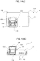
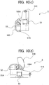
- each of the engaged sections 53 includes the pressing piece 54, a side wall 55, a lever pivot section 56 extending from the casing 51, a lever 57 provided to be pivotally movable about the lever pivot section 56, and a restricting section 58 that restricts pivotal movement of the lever 57.
- the pressing piece 54 is a substantially squared-U shaped member, and has an upper end section 54B and a lower end section 54C both protruding from a base body 54A.
- the distance between the base body 54A and the side wall 55 is larger than the plate thickness of the engaging member 22E, whereas the distance between the lower end section 54C and the side wall 55 is smaller than the plate thickness of the engaging member 22E.
- the pressing piece 54 is pressed outwardly in the left-right direction by a spring (not shown), and the pressing piece 54 is supported by abutment of the base body 54A against a protruding section 55A protruding toward the base body 54A from the side wall 55.
- the lever 57 is pressed outwardly in the left-right direction by a spring (not shown) or the restricting section 58, and is supported by the casing 51 at a position away from the pressing piece 54 and the restricting section 58.
- the user presses the inverter unit 5 against the housing 2 in a state where the engaging member 22E and the engaged sections 53 confront each other, and then the engaging member 22E causes the lower end section 54C to move toward the center in the left-right direction against the pressing force of the spring (not shown), and enters a space between the base body 54A and the side wall 55. Then, the lower end section 54C fits in the through hole 22c ( Fig. 5 ) of the engaging member 22E, and the inverter unit 5 is fixed onto the top flat surface 22A of the upper section 22.
- belt hook sections 51E are provided on front parts of the left and right side surfaces of the casing 51.
- the belt hook sections 51E are for using the inverter unit 5 in a state separated from the housing 2.
- the user can carry the inverter unit 5 with the belt 84 on his shoulder or waist.
- the power tool 1 AC power can be supplied from the battery pack 52 to the motor 7 by connecting the first cord 43 to the power cord 81, without connecting to an external AC power source via an extension cord (not shown). Hence, the power tool 1 can be used even at locations away from an external AC power source. Additionally, even in a situation where work is done near the external power source, if the first cord 43 is connected to the power cord 81, the user is not bothered by the extension cord (not shown) during work, thereby improving operability.
- the first cord 43 may be connected to the extension cord (not shown) so that AC voltage can be supplied directly from the external power source to the motor 7. Because the inverter unit 5 is not used in this case, the entire power tool 1 can be lightweight by detaching the inverter unit 5, thereby improving operability. In this case, the inverter unit 5 and the battery pack 52 can be used with another power tool.
- the inverter unit 5 is fixed to the housing 2 by the engaging member 22E and the engaged sections 53, thereby preventing the inverter unit 5 from dropping off and from being electrically disconnected during use of the power tool 1. Because the latch mechanism by the engaging member 22E and the engaged sections 53 is adopted, the user can mount and dismount the inverter unit 5 easily.
- the holding section 41 can be oriented at a position that is easy for the user to work. Further, the inverter unit 5 is arranged between the pair of imaginary planes including the trajectories formed when the pair of arm sections 42 is pivotally moved, which prevents the inverter unit 5 and the arm sections 42 from contacting each other and being broken when the arm sections 42 are pivotally moved.
- the inverter unit 5 is arranged between the one end sections 42A of the pair of arm sections 42 on the top flat surface 22A.
- the second cord 44 extending from the terminal section 22D to the holding section 41 can be pivotally moved together with the arm sections 42, thereby preventing the second cord 44 from being broken or disconnected during the pivotal movement.
- the battery pack 52 is detachable from the inverter unit 5, it is not necessary to carry the inverter unit 5 together with the battery pack 52 to a charging place when the charging-type battery pack 52 is to be charged. In addition, the battery pack 52 can be used for another power tool.
- the mount section 51 A has the rail receiving section 51D that receives the rail section 52A of the battery pack 52, the battery pack 52 can be mounted on the inverter unit 5 easily.
- the user can carry the inverter unit 5 separate from the housing 2.
- the inverter unit 5 can be carried in a detached state from the housing 2, thereby making the weight of the housing 2 and its attachment lighter and improving operability.
- mowing work can be performed by putting the inverter unit 5 on the user's shoulder.
- the inverter unit 5 can be used by itself.
- the inverter unit 5 is provided with the belt hook sections 51E for using the inverter unit 5 separate from the housing 2.
- the belt 84 or the like can be attached to the inverter unit 5 when the inverter unit 5 is used by itself, which improves operability.
- the output plug 51C of the inverter unit 5 is provided on a surface different from the engaged sections 53, the power cord 81 of the power tool 1 does not hinder mounting and dismounting of the inverter unit 5.
- the output plug 51 C is positioned between the arm sections 42 when the arm sections 42 are at the normal state, which suppresses an unexpected detachment of the power cord 81 from the output plug 51C.
- the output plug 51C and the belt hook sections 51E are provided on different surfaces. Hence, when the user carries and uses only the inverter unit 5, the belt 84 and the power cord 81 do not get in the way each other. Specifically, the output plug 51C is located at a lower position of the inverter unit 5. Hence, when the belt 84 is attached to the belt hook sections 51E for carrying the inverter unit 5, the power cord 81 connected to the output plug 51C does not get in the way. Further, the power cord 81 for outputting AC power is detachably connected to the output plug 51C, and the charging cord 83 connected to the external power source is detachably connected to the input plug 51B.
- the power cord 81 and the charging cord 83 can be connected and disconnected depending on usage conditions of the inverter unit 5, and the user is not bothered by the power cord 81 and the charging cord 83, thereby improving operability.
- the charging cord 83 can be detached from the inverter unit 5.
- the user is not subject to restrictions on work area.
- the inverter unit 5 is disposed at an upper position higher than the motor 7, which prevents the inverter unit 5 from being hit by another object during use.
- the lower section 21 confronts the ground surface during use of the lawnmower.
- the inverter unit 5 hits the ground surface, stones, and the like. This can be avoided according to the above-described embodiment.
- the motor 7 does not get in the way.
- the inverter unit 5 is detachable from the housing 2, mounting and dismounting of the inverter unit 5 can be made easy.
- the motor 7 and the rotary blade 7A have relatively large weight, weight balance can be improved with a relatively large weight of the inverter unit 5.
- the rotary blade 7A can be urged downward by the inverter unit 5 having a relatively large weight. Especially, in a case of a lawnmower, this can prevent the rotary blade 7A from lifting from the ground surface, and prevent the rotary blade 7A from becoming unstable during lawn mowing.
- the inverter unit 5 is located at a position further forward than the rear wall section 23 and further forward than the rear-wheel rotational axis (not shown).
- the projected position of the inverter unit 5 in the vertical direction is in a range from the rear-wheel rotational axis (not shown) to the front-wheel rotational axis (not shown).
- This feature can suppress falling over of the power tool 1 rearward due to a relatively large weight of the inverter unit 5. Especially, in a case of a lawnmower, the power tool 1 is sometimes leaned rearward in order to adjust cutting depth into lawn. In such a situation, the above-described feature can effectively suppress falling over of the power tool 1 rearward.
- the inverter unit 5 is fixed on the top flat surface 22A of the upper section 22.
- the inverter unit 5 can be arranged at a position away from a part where the adjustment knob 22C for adjusting cutting depth is provided, which enables effective utilization of dead space.
- the part of the upper section 22 at which the engaging member 22E is provided is further forward than the pivotal axis of the one end section 42A of the arm section 42. Hence, when engagement/disengagement of the engaging member 22E to/from the engaged section 53 during use of the power tool 1, the arm sections 42 can be prevented from hindering engagement/disengagement work.
- the inverter unit 5 may include a cover 100 that covers the battery pack 52 and the mount section 51A.
- the cover 100 is provided at an upper part of the casing 51. According to the first modification, the battery pack 52 and the mount section 51A can be protected from dusts and the like.
- the cover 100 is configured to pivotally move about pivotal supports 100A.
- a latch mechanism for fixing the cover 100 to the casing 51 of the inverter unit 5 may be provided, so that the cover 100 does not open due to vibrations or the like during use of the power tool and the battery pack 52 can be maintained in a covered state by the cover 100.
- a single battery pack 52 is mounted on the mount section 51A.
- the mount section may be so configured that a plurality of battery packs 52 can be mounted thereon. According to this configuration, power can be supplied for a longer period by using the plurality of battery packs 52 sequentially, compared with the case where the single battery pack 52 is mounted.
- the latch mechanism including the engaging member 22E and the engaged section 53 is adopted as fixing means for fixing the inverter unit 5 to the housing 2.
- a latch section may be provided on the housing 2 and a latch receiving section may be provided on the inverter unit 5.
- the inverter unit 5 and the housing 2 may be fixed by a band, or a locking switch for restricting movement of the pressing piece 54 may be provided on the holding section 41.
- the inverter unit 5 may be fixed to the housing 2 by a sliding mechanism, or may be fixed to the housing 2 by an insertion mechanism.
- the battery pack 52 is guided to the mount section 51A by sliding along the rail.
- the battery pack 52 may be guided to the mount section 51A by an insertion mechanism.
- connection between the battery pack 52 and the inverter unit 5 (the mount section 51A) may be done only by sliding, without using the latch mechanism.
- the position at which the inverter unit 5 is arranged is not limited to the position of the inverter unit 5 in the above-describe embodiment and the first modification.
- the inverter unit 5 is arranged directly above the rotary blade 7A in the above-describe embodiment, but the position of the inverter unit 5 is not limited to directly above the rotary blade 7A.
- the projected position of the inverter unit 5 in the vertical direction may be in a range from the motor 7 to the rotary blade 7A.
- the lever 57 and the pressing piece 54 of the engaged section 53 shown in Fig. 6 may be formed as an integral part.
- the engaged section 53 is urged outwardly in the left-right direction by a spring (not shown). It is so configured that the lever 57 pivotally moves about the lever pivot section 56 when the engaged section 53 (the lever 57) is pressed against the urging force of the spring.
- a tapered section may be provided at the lower end section 54C of the pressing piece 54. In this case, the tapered section can be provided so that, when the inverter unit 5 is mounted on the housing 2, the tapered section abuts on the engaging member 22E without operating the engaged section 53 and the lower end section 54C moves inwardly in the left-right direction.
- the through hole 22c is formed in the engaging member 22E.
- another shape may be used as long as the above-described pressing piece 54 can engage.
- a concave and convex shape may be used instead of the through hole.
- the pair of arm sections 42 may be so configured that its lengthwise size can be adjusted.
- an arm section 142 of a power tool 101 according to a second modification may include an adjustment member 142C.
- the length of the arm section 142 can be fixed by adjusting the pair of arm section 142 to a desired length and subsequently rotating the adjustment member 142C.
- it may be also configured such that the length of the arm section 142 can be adjusted finely by rotating the adjustment member 142C.
- the invention can be applied to power tools such as hedge trimmers (cutters), lawn trimmers (cutters), brushcutters, etc.
- a hand-held hedge trimmer (cutter) 201 serving as a power tool according to a third modification.
- the hedge trimmer 201 includes a housing 202, handles 203 and 204 each extending from the housing 202 and provided for being gripped by a user, an inverter unit 205 provided detachably on a lower side of the handle 204, a motor 207 driven by power supplied from the inverter unit 205, and a cutting blade 208 for performing trimming (cutting) work in conjunction with rotation of the output shaft of the motor 207.
- the inverter unit 205 has a rail section (not shown), and is mounted while being slid along a rail receiving section (not shown) provided on the handle 204.
- a power tool of the invention is especially useful in a field of mowers and the like that are used at outdoor places away from outlets.
Landscapes
- Engineering & Computer Science (AREA)
- Mechanical Engineering (AREA)
- Life Sciences & Earth Sciences (AREA)
- Environmental Sciences (AREA)
- Portable Power Tools In General (AREA)
- Harvester Elements (AREA)
Applications Claiming Priority (2)
| Application Number | Priority Date | Filing Date | Title |
|---|---|---|---|
| JP2010130970A JP5545476B2 (ja) | 2010-06-08 | 2010-06-08 | 電動工具 |
| PCT/JP2011/063435 WO2011155626A1 (en) | 2010-06-08 | 2011-06-06 | Power tool |
Publications (2)
| Publication Number | Publication Date |
|---|---|
| EP2580025A1 EP2580025A1 (en) | 2013-04-17 |
| EP2580025B1 true EP2580025B1 (en) | 2017-01-11 |
Family
ID=44627900
Family Applications (1)
| Application Number | Title | Priority Date | Filing Date |
|---|---|---|---|
| EP11729480.1A Active EP2580025B1 (en) | 2010-06-08 | 2011-06-06 | Power tool |
Country Status (12)
| Country | Link |
|---|---|
| US (1) | US9254563B2 (zh) |
| EP (1) | EP2580025B1 (zh) |
| JP (1) | JP5545476B2 (zh) |
| KR (1) | KR20130004518A (zh) |
| CN (1) | CN102933354B (zh) |
| AU (1) | AU2011262777B2 (zh) |
| BR (1) | BR112012027738A2 (zh) |
| CA (1) | CA2797770A1 (zh) |
| MX (1) | MX2012014134A (zh) |
| RU (1) | RU2012157624A (zh) |
| TW (1) | TWI471087B (zh) |
| WO (1) | WO2011155626A1 (zh) |
Families Citing this family (10)
| Publication number | Priority date | Publication date | Assignee | Title |
|---|---|---|---|---|
| JP5697553B2 (ja) * | 2011-06-14 | 2015-04-08 | 株式会社マキタ | バッテリ装置 |
| JP5694066B2 (ja) * | 2011-06-14 | 2015-04-01 | 株式会社マキタ | バッテリ装置 |
| JP5666387B2 (ja) * | 2011-06-14 | 2015-02-12 | 株式会社マキタ | バッテリ装置 |
| WO2014147366A1 (en) | 2013-03-21 | 2014-09-25 | Tws (Macau Commercial Offshore ) Limited | Ac power supply |
| US10131042B2 (en) | 2013-10-21 | 2018-11-20 | Milwaukee Electric Tool Corporation | Adapter for power tool devices |
| JP2016049599A (ja) * | 2014-08-29 | 2016-04-11 | パナソニックIpマネジメント株式会社 | 電動工具 |
| CN105471146A (zh) | 2014-09-04 | 2016-04-06 | 苏州宝时得电动工具有限公司 | 电动工具 |
| TWI680347B (zh) * | 2015-12-29 | 2019-12-21 | 日商Hoya股份有限公司 | 光罩基板、光罩基底、光罩、光罩基板之製造方法、光罩之製造方法、及顯示裝置之製造方法 |
| USD1009790S1 (en) | 2020-03-19 | 2024-01-02 | Milwaukee Electric Tool Corporation | Single battery pack inverter |
| US11950531B1 (en) | 2021-04-01 | 2024-04-09 | CoJa Industries, LLC | Trimmer attachment for lawn mower |
Family Cites Families (31)
| Publication number | Priority date | Publication date | Assignee | Title |
|---|---|---|---|---|
| US3919615A (en) * | 1974-03-18 | 1975-11-11 | Ronald Niecke | Power belt |
| DE3643558A1 (de) | 1986-12-19 | 1988-07-07 | Wolf Geraete Gmbh | Elektromotorisches antriebssystem |
| SE8802566L (sv) * | 1988-07-08 | 1990-01-09 | Atlas Copco Tools Ab | Motordrivet verktyg och drivsystem foer detta |
| DE4301508A1 (de) * | 1993-01-21 | 1994-07-28 | Josef Gail | Elektro-Werkzeug |
| US5606851A (en) * | 1993-09-22 | 1997-03-04 | Briggs & Stratton Corporation | Battery-powered lawn cutting system |
| US5787693A (en) | 1994-10-28 | 1998-08-04 | Black & Decker Inc. | Universal, retrofittable powerhead for small gasoline engine power implements |
| CN2289338Y (zh) | 1996-10-29 | 1998-08-26 | 青海省新能源研究所 | 便携式交直流两用太阳能电源装置 |
| JP3888492B2 (ja) * | 1997-12-19 | 2007-03-07 | 古河機械金属株式会社 | 衝撃装置 |
| JP3615937B2 (ja) | 1998-06-10 | 2005-02-02 | 株式会社マキタ | スライド式ハンドル機構 |
| US6577098B2 (en) | 2000-05-17 | 2003-06-10 | Delphi Technologies, Inc. | Apparatus and method for providing a mobile AC power supply |
| JP3996733B2 (ja) * | 2000-11-06 | 2007-10-24 | 株式会社日立製作所 | リニアモータ付電動工具 |
| TWI248783B (en) | 2001-08-22 | 2006-02-11 | Honda Motor Co Ltd | Electric lawn mower |
| US20030121682A1 (en) * | 2001-12-28 | 2003-07-03 | Carrancho Tony M. | Independent electrical implement system |
| US6971951B2 (en) | 2002-09-19 | 2005-12-06 | Wmh Tool Group, Inc. | Power tool with portable power source |
| JP4487836B2 (ja) * | 2005-04-20 | 2010-06-23 | 日立工機株式会社 | 電動工具 |
| JP4339275B2 (ja) * | 2005-05-12 | 2009-10-07 | 株式会社エスティック | インパクト式のネジ締め装置の制御方法および装置 |
| JP4400519B2 (ja) * | 2005-06-30 | 2010-01-20 | パナソニック電工株式会社 | インパクト回転工具 |
| US20070141403A1 (en) | 2005-12-21 | 2007-06-21 | Willis Haywood | Portable battery unit featuring two standard AC type sockets, a carry handle, on/off switch, adapter/battery recharge socket, rechargeable battery, and inverter circuit |
| CN200956389Y (zh) | 2006-01-12 | 2007-10-03 | 嘉善宝狮电子有限公司 | 电动园林工具电源、充电两用器 |
| GB0615241D0 (en) | 2006-08-01 | 2006-09-06 | Bosch Gmbh Robert | Lawn-care apparatus |
| US7479754B2 (en) | 2006-10-17 | 2009-01-20 | Desa Ip Llc | Hybrid electric lawnmower |
| US7884560B2 (en) * | 2006-10-17 | 2011-02-08 | Mtd Products Inc | Hybrid electric device |
| US7728534B2 (en) | 2006-10-17 | 2010-06-01 | Mtd Products Inc | Hybrid electric lawnmower |
| EP2115849A4 (en) * | 2007-02-26 | 2015-12-23 | Black & Decker Inc | PORTABLE POWER |
| CN201113488Y (zh) | 2007-07-06 | 2008-09-10 | 叶少军 | 带有逆变器的便携式太阳能供电装置 |
| JP4104648B1 (ja) * | 2007-09-13 | 2008-06-18 | 和征 榊原 | 電池パック |
| EP2190628B1 (en) * | 2007-09-21 | 2016-03-23 | Hitachi Koki CO., LTD. | Impact tool |
| JP5071665B2 (ja) | 2008-03-17 | 2012-11-14 | 日立工機株式会社 | 芝刈機 |
| US7839019B2 (en) | 2008-05-30 | 2010-11-23 | Chun-Chieh Chang | Multipurpose portable storage and supply system |
| JP2010130970A (ja) | 2008-12-05 | 2010-06-17 | Yakult Health Foods Co Ltd | 湯分散性の良い青汁粉末及びその製造方法 |
| CN201430783Y (zh) | 2009-05-13 | 2010-03-31 | 浙江利欧股份有限公司 | 一种手推式电动割草机 |
-
2010
- 2010-06-08 JP JP2010130970A patent/JP5545476B2/ja active Active
-
2011
- 2011-06-06 KR KR1020127030622A patent/KR20130004518A/ko active IP Right Grant
- 2011-06-06 CN CN201180028479.4A patent/CN102933354B/zh active Active
- 2011-06-06 MX MX2012014134A patent/MX2012014134A/es active IP Right Grant
- 2011-06-06 US US13/698,361 patent/US9254563B2/en active Active
- 2011-06-06 AU AU2011262777A patent/AU2011262777B2/en not_active Ceased
- 2011-06-06 WO PCT/JP2011/063435 patent/WO2011155626A1/en active Application Filing
- 2011-06-06 BR BR112012027738A patent/BR112012027738A2/pt not_active IP Right Cessation
- 2011-06-06 EP EP11729480.1A patent/EP2580025B1/en active Active
- 2011-06-06 RU RU2012157624/02A patent/RU2012157624A/ru not_active Application Discontinuation
- 2011-06-06 CA CA2797770A patent/CA2797770A1/en not_active Abandoned
- 2011-06-08 TW TW100119941A patent/TWI471087B/zh not_active IP Right Cessation
Non-Patent Citations (1)
| Title |
|---|
| None * |
Also Published As
| Publication number | Publication date |
|---|---|
| TWI471087B (zh) | 2015-02-01 |
| CA2797770A1 (en) | 2011-12-15 |
| JP2011255446A (ja) | 2011-12-22 |
| TW201208555A (en) | 2012-03-01 |
| WO2011155626A1 (en) | 2011-12-15 |
| EP2580025A1 (en) | 2013-04-17 |
| MX2012014134A (es) | 2013-02-07 |
| AU2011262777B2 (en) | 2014-08-21 |
| KR20130004518A (ko) | 2013-01-10 |
| RU2012157624A (ru) | 2014-07-20 |
| CN102933354A (zh) | 2013-02-13 |
| US20130068493A1 (en) | 2013-03-21 |
| JP5545476B2 (ja) | 2014-07-09 |
| BR112012027738A2 (pt) | 2016-09-13 |
| US9254563B2 (en) | 2016-02-09 |
| CN102933354B (zh) | 2016-05-18 |
Similar Documents
| Publication | Publication Date | Title |
|---|---|---|
| EP2580025B1 (en) | Power tool | |
| AU2011262777A1 (en) | Power tool | |
| EP2580024B1 (en) | Power tool | |
| US8910459B2 (en) | Electric lawn mowers | |
| EP2561742A1 (en) | Electric-powered cultivator | |
| RU2581485C2 (ru) | Электрические газонокосилки | |
| EP2534938B1 (en) | Electric lawn mowers | |
| JP2016049048A (ja) | 芝刈機 | |
| US9169609B2 (en) | Removable lamp for outdoor power equipment | |
| JP2022113136A (ja) | 作業機 | |
| JP5912305B2 (ja) | 電動芝刈機 | |
| JP6568418B2 (ja) | 手持ち式の充電式電動工具用の延長ハンドル | |
| JP7469900B2 (ja) | 作業用機器 | |
| CN114784442A (zh) | 作业机械 | |
| JP2021014123A (ja) | 自動かんな盤 |
Legal Events
| Date | Code | Title | Description |
|---|---|---|---|
| PUAI | Public reference made under article 153(3) epc to a published international application that has entered the european phase |
Free format text: ORIGINAL CODE: 0009012 |
|
| 17P | Request for examination filed |
Effective date: 20121219 |
|
| AK | Designated contracting states |
Kind code of ref document: A1 Designated state(s): AL AT BE BG CH CY CZ DE DK EE ES FI FR GB GR HR HU IE IS IT LI LT LU LV MC MK MT NL NO PL PT RO RS SE SI SK SM TR |
|
| DAX | Request for extension of the european patent (deleted) | ||
| GRAP | Despatch of communication of intention to grant a patent |
Free format text: ORIGINAL CODE: EPIDOSNIGR1 |
|
| GRAJ | Information related to disapproval of communication of intention to grant by the applicant or resumption of examination proceedings by the epo deleted |
Free format text: ORIGINAL CODE: EPIDOSDIGR1 |
|
| INTG | Intention to grant announced |
Effective date: 20160712 |
|
| GRAP | Despatch of communication of intention to grant a patent |
Free format text: ORIGINAL CODE: EPIDOSNIGR1 |
|
| INTC | Intention to grant announced (deleted) | ||
| INTG | Intention to grant announced |
Effective date: 20160823 |
|
| GRAS | Grant fee paid |
Free format text: ORIGINAL CODE: EPIDOSNIGR3 |
|
| GRAA | (expected) grant |
Free format text: ORIGINAL CODE: 0009210 |
|
| AK | Designated contracting states |
Kind code of ref document: B1 Designated state(s): AL AT BE BG CH CY CZ DE DK EE ES FI FR GB GR HR HU IE IS IT LI LT LU LV MC MK MT NL NO PL PT RO RS SE SI SK SM TR |
|
| REG | Reference to a national code |
Ref country code: GB Ref legal event code: FG4D |
|
| REG | Reference to a national code |
Ref country code: CH Ref legal event code: EP |
|
| REG | Reference to a national code |
Ref country code: AT Ref legal event code: REF Ref document number: 860827 Country of ref document: AT Kind code of ref document: T Effective date: 20170115 |
|
| REG | Reference to a national code |
Ref country code: IE Ref legal event code: FG4D |
|
| REG | Reference to a national code |
Ref country code: DE Ref legal event code: R096 Ref document number: 602011034261 Country of ref document: DE |
|
| REG | Reference to a national code |
Ref country code: LT Ref legal event code: MG4D |
|
| REG | Reference to a national code |
Ref country code: FR Ref legal event code: PLFP Year of fee payment: 7 |
|
| REG | Reference to a national code |
Ref country code: NL Ref legal event code: MP Effective date: 20170111 |
|
| REG | Reference to a national code |
Ref country code: AT Ref legal event code: MK05 Ref document number: 860827 Country of ref document: AT Kind code of ref document: T Effective date: 20170111 |
|
| PG25 | Lapsed in a contracting state [announced via postgrant information from national office to epo] |
Ref country code: NL Free format text: LAPSE BECAUSE OF FAILURE TO SUBMIT A TRANSLATION OF THE DESCRIPTION OR TO PAY THE FEE WITHIN THE PRESCRIBED TIME-LIMIT Effective date: 20170111 |
|
| PG25 | Lapsed in a contracting state [announced via postgrant information from national office to epo] |
Ref country code: IS Free format text: LAPSE BECAUSE OF FAILURE TO SUBMIT A TRANSLATION OF THE DESCRIPTION OR TO PAY THE FEE WITHIN THE PRESCRIBED TIME-LIMIT Effective date: 20170511 Ref country code: HR Free format text: LAPSE BECAUSE OF FAILURE TO SUBMIT A TRANSLATION OF THE DESCRIPTION OR TO PAY THE FEE WITHIN THE PRESCRIBED TIME-LIMIT Effective date: 20170111 Ref country code: NO Free format text: LAPSE BECAUSE OF FAILURE TO SUBMIT A TRANSLATION OF THE DESCRIPTION OR TO PAY THE FEE WITHIN THE PRESCRIBED TIME-LIMIT Effective date: 20170411 Ref country code: GR Free format text: LAPSE BECAUSE OF FAILURE TO SUBMIT A TRANSLATION OF THE DESCRIPTION OR TO PAY THE FEE WITHIN THE PRESCRIBED TIME-LIMIT Effective date: 20170412 Ref country code: LT Free format text: LAPSE BECAUSE OF FAILURE TO SUBMIT A TRANSLATION OF THE DESCRIPTION OR TO PAY THE FEE WITHIN THE PRESCRIBED TIME-LIMIT Effective date: 20170111 Ref country code: FI Free format text: LAPSE BECAUSE OF FAILURE TO SUBMIT A TRANSLATION OF THE DESCRIPTION OR TO PAY THE FEE WITHIN THE PRESCRIBED TIME-LIMIT Effective date: 20170111 |
|
| PG25 | Lapsed in a contracting state [announced via postgrant information from national office to epo] |
Ref country code: PL Free format text: LAPSE BECAUSE OF FAILURE TO SUBMIT A TRANSLATION OF THE DESCRIPTION OR TO PAY THE FEE WITHIN THE PRESCRIBED TIME-LIMIT Effective date: 20170111 Ref country code: LV Free format text: LAPSE BECAUSE OF FAILURE TO SUBMIT A TRANSLATION OF THE DESCRIPTION OR TO PAY THE FEE WITHIN THE PRESCRIBED TIME-LIMIT Effective date: 20170111 Ref country code: SE Free format text: LAPSE BECAUSE OF FAILURE TO SUBMIT A TRANSLATION OF THE DESCRIPTION OR TO PAY THE FEE WITHIN THE PRESCRIBED TIME-LIMIT Effective date: 20170111 Ref country code: AT Free format text: LAPSE BECAUSE OF FAILURE TO SUBMIT A TRANSLATION OF THE DESCRIPTION OR TO PAY THE FEE WITHIN THE PRESCRIBED TIME-LIMIT Effective date: 20170111 Ref country code: BG Free format text: LAPSE BECAUSE OF FAILURE TO SUBMIT A TRANSLATION OF THE DESCRIPTION OR TO PAY THE FEE WITHIN THE PRESCRIBED TIME-LIMIT Effective date: 20170411 Ref country code: RS Free format text: LAPSE BECAUSE OF FAILURE TO SUBMIT A TRANSLATION OF THE DESCRIPTION OR TO PAY THE FEE WITHIN THE PRESCRIBED TIME-LIMIT Effective date: 20170111 Ref country code: PT Free format text: LAPSE BECAUSE OF FAILURE TO SUBMIT A TRANSLATION OF THE DESCRIPTION OR TO PAY THE FEE WITHIN THE PRESCRIBED TIME-LIMIT Effective date: 20170511 Ref country code: ES Free format text: LAPSE BECAUSE OF FAILURE TO SUBMIT A TRANSLATION OF THE DESCRIPTION OR TO PAY THE FEE WITHIN THE PRESCRIBED TIME-LIMIT Effective date: 20170111 |
|
| REG | Reference to a national code |
Ref country code: DE Ref legal event code: R097 Ref document number: 602011034261 Country of ref document: DE |
|
| PG25 | Lapsed in a contracting state [announced via postgrant information from national office to epo] |
Ref country code: IT Free format text: LAPSE BECAUSE OF FAILURE TO SUBMIT A TRANSLATION OF THE DESCRIPTION OR TO PAY THE FEE WITHIN THE PRESCRIBED TIME-LIMIT Effective date: 20170111 Ref country code: SK Free format text: LAPSE BECAUSE OF FAILURE TO SUBMIT A TRANSLATION OF THE DESCRIPTION OR TO PAY THE FEE WITHIN THE PRESCRIBED TIME-LIMIT Effective date: 20170111 Ref country code: EE Free format text: LAPSE BECAUSE OF FAILURE TO SUBMIT A TRANSLATION OF THE DESCRIPTION OR TO PAY THE FEE WITHIN THE PRESCRIBED TIME-LIMIT Effective date: 20170111 Ref country code: RO Free format text: LAPSE BECAUSE OF FAILURE TO SUBMIT A TRANSLATION OF THE DESCRIPTION OR TO PAY THE FEE WITHIN THE PRESCRIBED TIME-LIMIT Effective date: 20170111 Ref country code: CZ Free format text: LAPSE BECAUSE OF FAILURE TO SUBMIT A TRANSLATION OF THE DESCRIPTION OR TO PAY THE FEE WITHIN THE PRESCRIBED TIME-LIMIT Effective date: 20170111 |
|
| PLBE | No opposition filed within time limit |
Free format text: ORIGINAL CODE: 0009261 |
|
| STAA | Information on the status of an ep patent application or granted ep patent |
Free format text: STATUS: NO OPPOSITION FILED WITHIN TIME LIMIT |
|
| PG25 | Lapsed in a contracting state [announced via postgrant information from national office to epo] |
Ref country code: DK Free format text: LAPSE BECAUSE OF FAILURE TO SUBMIT A TRANSLATION OF THE DESCRIPTION OR TO PAY THE FEE WITHIN THE PRESCRIBED TIME-LIMIT Effective date: 20170111 Ref country code: SM Free format text: LAPSE BECAUSE OF FAILURE TO SUBMIT A TRANSLATION OF THE DESCRIPTION OR TO PAY THE FEE WITHIN THE PRESCRIBED TIME-LIMIT Effective date: 20170111 |
|
| 26N | No opposition filed |
Effective date: 20171012 |
|
| PG25 | Lapsed in a contracting state [announced via postgrant information from national office to epo] |
Ref country code: MC Free format text: LAPSE BECAUSE OF FAILURE TO SUBMIT A TRANSLATION OF THE DESCRIPTION OR TO PAY THE FEE WITHIN THE PRESCRIBED TIME-LIMIT Effective date: 20170111 |
|
| REG | Reference to a national code |
Ref country code: CH Ref legal event code: PL |
|
| PG25 | Lapsed in a contracting state [announced via postgrant information from national office to epo] |
Ref country code: SI Free format text: LAPSE BECAUSE OF FAILURE TO SUBMIT A TRANSLATION OF THE DESCRIPTION OR TO PAY THE FEE WITHIN THE PRESCRIBED TIME-LIMIT Effective date: 20170111 |
|
| REG | Reference to a national code |
Ref country code: IE Ref legal event code: MM4A |
|
| PG25 | Lapsed in a contracting state [announced via postgrant information from national office to epo] |
Ref country code: IE Free format text: LAPSE BECAUSE OF NON-PAYMENT OF DUE FEES Effective date: 20170606 Ref country code: LI Free format text: LAPSE BECAUSE OF NON-PAYMENT OF DUE FEES Effective date: 20170630 Ref country code: CH Free format text: LAPSE BECAUSE OF NON-PAYMENT OF DUE FEES Effective date: 20170630 Ref country code: LU Free format text: LAPSE BECAUSE OF NON-PAYMENT OF DUE FEES Effective date: 20170606 |
|
| REG | Reference to a national code |
Ref country code: FR Ref legal event code: PLFP Year of fee payment: 8 |
|
| REG | Reference to a national code |
Ref country code: BE Ref legal event code: MM Effective date: 20170630 |
|
| REG | Reference to a national code |
Ref country code: DE Ref legal event code: R081 Ref document number: 602011034261 Country of ref document: DE Owner name: KOKI HOLDINGS CO., LTD., JP Free format text: FORMER OWNER: HITACHI KOKI CO., LTD., TOKYO, JP |
|
| PG25 | Lapsed in a contracting state [announced via postgrant information from national office to epo] |
Ref country code: BE Free format text: LAPSE BECAUSE OF NON-PAYMENT OF DUE FEES Effective date: 20170630 |
|
| REG | Reference to a national code |
Ref country code: DE Ref legal event code: R084 Ref document number: 602011034261 Country of ref document: DE |
|
| PG25 | Lapsed in a contracting state [announced via postgrant information from national office to epo] |
Ref country code: MT Free format text: LAPSE BECAUSE OF NON-PAYMENT OF DUE FEES Effective date: 20170606 |
|
| REG | Reference to a national code |
Ref country code: GB Ref legal event code: 746 Effective date: 20181030 |
|
| PG25 | Lapsed in a contracting state [announced via postgrant information from national office to epo] |
Ref country code: HU Free format text: LAPSE BECAUSE OF FAILURE TO SUBMIT A TRANSLATION OF THE DESCRIPTION OR TO PAY THE FEE WITHIN THE PRESCRIBED TIME-LIMIT; INVALID AB INITIO Effective date: 20110606 |
|
| PG25 | Lapsed in a contracting state [announced via postgrant information from national office to epo] |
Ref country code: CY Free format text: LAPSE BECAUSE OF NON-PAYMENT OF DUE FEES Effective date: 20170111 |
|
| PG25 | Lapsed in a contracting state [announced via postgrant information from national office to epo] |
Ref country code: MK Free format text: LAPSE BECAUSE OF FAILURE TO SUBMIT A TRANSLATION OF THE DESCRIPTION OR TO PAY THE FEE WITHIN THE PRESCRIBED TIME-LIMIT Effective date: 20170111 |
|
| PG25 | Lapsed in a contracting state [announced via postgrant information from national office to epo] |
Ref country code: TR Free format text: LAPSE BECAUSE OF FAILURE TO SUBMIT A TRANSLATION OF THE DESCRIPTION OR TO PAY THE FEE WITHIN THE PRESCRIBED TIME-LIMIT Effective date: 20170111 |
|
| PG25 | Lapsed in a contracting state [announced via postgrant information from national office to epo] |
Ref country code: AL Free format text: LAPSE BECAUSE OF FAILURE TO SUBMIT A TRANSLATION OF THE DESCRIPTION OR TO PAY THE FEE WITHIN THE PRESCRIBED TIME-LIMIT Effective date: 20170111 |
|
| PGFP | Annual fee paid to national office [announced via postgrant information from national office to epo] |
Ref country code: GB Payment date: 20240621 Year of fee payment: 14 |
|
| PGFP | Annual fee paid to national office [announced via postgrant information from national office to epo] |
Ref country code: DE Payment date: 20240619 Year of fee payment: 14 |
|
| PGFP | Annual fee paid to national office [announced via postgrant information from national office to epo] |
Ref country code: FR Payment date: 20240628 Year of fee payment: 14 |