EP2579005A1 - Encodeur rotatif, moteur rotatif et système à moteur rotatif - Google Patents
Encodeur rotatif, moteur rotatif et système à moteur rotatif Download PDFInfo
- Publication number
- EP2579005A1 EP2579005A1 EP11789488.1A EP11789488A EP2579005A1 EP 2579005 A1 EP2579005 A1 EP 2579005A1 EP 11789488 A EP11789488 A EP 11789488A EP 2579005 A1 EP2579005 A1 EP 2579005A1
- Authority
- EP
- European Patent Office
- Prior art keywords
- slits
- origin
- grating
- disk
- tracks
- Prior art date
- Legal status (The legal status is an assumption and is not a legal conclusion. Google has not performed a legal analysis and makes no representation as to the accuracy of the status listed.)
- Withdrawn
Links
- 238000001514 detection method Methods 0.000 claims abstract description 199
- 230000003287 optical effect Effects 0.000 claims abstract description 117
- 230000000737 periodic effect Effects 0.000 claims description 62
- 239000011295 pitch Substances 0.000 abstract description 88
- 238000004519 manufacturing process Methods 0.000 abstract description 32
- 230000007246 mechanism Effects 0.000 description 59
- 238000012545 processing Methods 0.000 description 22
- 230000015572 biosynthetic process Effects 0.000 description 18
- 238000011161 development Methods 0.000 description 17
- 238000000034 method Methods 0.000 description 13
- 230000008859 change Effects 0.000 description 10
- 230000000694 effects Effects 0.000 description 9
- 239000000463 material Substances 0.000 description 8
- 230000001133 acceleration Effects 0.000 description 5
- 230000007423 decrease Effects 0.000 description 4
- 238000009792 diffusion process Methods 0.000 description 4
- 230000001965 increasing effect Effects 0.000 description 4
- 238000009434 installation Methods 0.000 description 3
- 230000003247 decreasing effect Effects 0.000 description 2
- 230000007613 environmental effect Effects 0.000 description 2
- 238000012986 modification Methods 0.000 description 2
- 230000004048 modification Effects 0.000 description 2
- 230000009467 reduction Effects 0.000 description 2
- 230000004044 response Effects 0.000 description 2
- 230000000903 blocking effect Effects 0.000 description 1
- 239000003638 chemical reducing agent Substances 0.000 description 1
- 238000000151 deposition Methods 0.000 description 1
- 238000013461 design Methods 0.000 description 1
- 230000005611 electricity Effects 0.000 description 1
- 230000002708 enhancing effect Effects 0.000 description 1
- 238000005530 etching Methods 0.000 description 1
- 230000010354 integration Effects 0.000 description 1
- 230000005389 magnetism Effects 0.000 description 1
- 238000007740 vapor deposition Methods 0.000 description 1
Images


Classifications
-
- G—PHYSICS
- G01—MEASURING; TESTING
- G01D—MEASURING NOT SPECIALLY ADAPTED FOR A SPECIFIC VARIABLE; ARRANGEMENTS FOR MEASURING TWO OR MORE VARIABLES NOT COVERED IN A SINGLE OTHER SUBCLASS; TARIFF METERING APPARATUS; MEASURING OR TESTING NOT OTHERWISE PROVIDED FOR
- G01D5/00—Mechanical means for transferring the output of a sensing member; Means for converting the output of a sensing member to another variable where the form or nature of the sensing member does not constrain the means for converting; Transducers not specially adapted for a specific variable
- G01D5/26—Mechanical means for transferring the output of a sensing member; Means for converting the output of a sensing member to another variable where the form or nature of the sensing member does not constrain the means for converting; Transducers not specially adapted for a specific variable characterised by optical transfer means, i.e. using infrared, visible, or ultraviolet light
- G01D5/32—Mechanical means for transferring the output of a sensing member; Means for converting the output of a sensing member to another variable where the form or nature of the sensing member does not constrain the means for converting; Transducers not specially adapted for a specific variable characterised by optical transfer means, i.e. using infrared, visible, or ultraviolet light with attenuation or whole or partial obturation of beams of light
- G01D5/34—Mechanical means for transferring the output of a sensing member; Means for converting the output of a sensing member to another variable where the form or nature of the sensing member does not constrain the means for converting; Transducers not specially adapted for a specific variable characterised by optical transfer means, i.e. using infrared, visible, or ultraviolet light with attenuation or whole or partial obturation of beams of light the beams of light being detected by photocells
-
- G—PHYSICS
- G01—MEASURING; TESTING
- G01D—MEASURING NOT SPECIALLY ADAPTED FOR A SPECIFIC VARIABLE; ARRANGEMENTS FOR MEASURING TWO OR MORE VARIABLES NOT COVERED IN A SINGLE OTHER SUBCLASS; TARIFF METERING APPARATUS; MEASURING OR TESTING NOT OTHERWISE PROVIDED FOR
- G01D5/00—Mechanical means for transferring the output of a sensing member; Means for converting the output of a sensing member to another variable where the form or nature of the sensing member does not constrain the means for converting; Transducers not specially adapted for a specific variable
- G01D5/12—Mechanical means for transferring the output of a sensing member; Means for converting the output of a sensing member to another variable where the form or nature of the sensing member does not constrain the means for converting; Transducers not specially adapted for a specific variable using electric or magnetic means
- G01D5/244—Mechanical means for transferring the output of a sensing member; Means for converting the output of a sensing member to another variable where the form or nature of the sensing member does not constrain the means for converting; Transducers not specially adapted for a specific variable using electric or magnetic means influencing characteristics of pulses or pulse trains; generating pulses or pulse trains
- G01D5/24428—Error prevention
- G01D5/24433—Error prevention by mechanical means
- G01D5/24438—Special design of the sensing element or scale
-
- G—PHYSICS
- G01—MEASURING; TESTING
- G01D—MEASURING NOT SPECIALLY ADAPTED FOR A SPECIFIC VARIABLE; ARRANGEMENTS FOR MEASURING TWO OR MORE VARIABLES NOT COVERED IN A SINGLE OTHER SUBCLASS; TARIFF METERING APPARATUS; MEASURING OR TESTING NOT OTHERWISE PROVIDED FOR
- G01D5/00—Mechanical means for transferring the output of a sensing member; Means for converting the output of a sensing member to another variable where the form or nature of the sensing member does not constrain the means for converting; Transducers not specially adapted for a specific variable
- G01D5/26—Mechanical means for transferring the output of a sensing member; Means for converting the output of a sensing member to another variable where the form or nature of the sensing member does not constrain the means for converting; Transducers not specially adapted for a specific variable characterised by optical transfer means, i.e. using infrared, visible, or ultraviolet light
- G01D5/32—Mechanical means for transferring the output of a sensing member; Means for converting the output of a sensing member to another variable where the form or nature of the sensing member does not constrain the means for converting; Transducers not specially adapted for a specific variable characterised by optical transfer means, i.e. using infrared, visible, or ultraviolet light with attenuation or whole or partial obturation of beams of light
- G01D5/34—Mechanical means for transferring the output of a sensing member; Means for converting the output of a sensing member to another variable where the form or nature of the sensing member does not constrain the means for converting; Transducers not specially adapted for a specific variable characterised by optical transfer means, i.e. using infrared, visible, or ultraviolet light with attenuation or whole or partial obturation of beams of light the beams of light being detected by photocells
- G01D5/347—Mechanical means for transferring the output of a sensing member; Means for converting the output of a sensing member to another variable where the form or nature of the sensing member does not constrain the means for converting; Transducers not specially adapted for a specific variable characterised by optical transfer means, i.e. using infrared, visible, or ultraviolet light with attenuation or whole or partial obturation of beams of light the beams of light being detected by photocells using displacement encoding scales
- G01D5/3473—Circular or rotary encoders
-
- G—PHYSICS
- G01—MEASURING; TESTING
- G01D—MEASURING NOT SPECIALLY ADAPTED FOR A SPECIFIC VARIABLE; ARRANGEMENTS FOR MEASURING TWO OR MORE VARIABLES NOT COVERED IN A SINGLE OTHER SUBCLASS; TARIFF METERING APPARATUS; MEASURING OR TESTING NOT OTHERWISE PROVIDED FOR
- G01D5/00—Mechanical means for transferring the output of a sensing member; Means for converting the output of a sensing member to another variable where the form or nature of the sensing member does not constrain the means for converting; Transducers not specially adapted for a specific variable
- G01D5/26—Mechanical means for transferring the output of a sensing member; Means for converting the output of a sensing member to another variable where the form or nature of the sensing member does not constrain the means for converting; Transducers not specially adapted for a specific variable characterised by optical transfer means, i.e. using infrared, visible, or ultraviolet light
- G01D5/32—Mechanical means for transferring the output of a sensing member; Means for converting the output of a sensing member to another variable where the form or nature of the sensing member does not constrain the means for converting; Transducers not specially adapted for a specific variable characterised by optical transfer means, i.e. using infrared, visible, or ultraviolet light with attenuation or whole or partial obturation of beams of light
- G01D5/34—Mechanical means for transferring the output of a sensing member; Means for converting the output of a sensing member to another variable where the form or nature of the sensing member does not constrain the means for converting; Transducers not specially adapted for a specific variable characterised by optical transfer means, i.e. using infrared, visible, or ultraviolet light with attenuation or whole or partial obturation of beams of light the beams of light being detected by photocells
- G01D5/36—Forming the light into pulses
- G01D5/38—Forming the light into pulses by diffraction gratings
-
- G—PHYSICS
- G05—CONTROLLING; REGULATING
- G05B—CONTROL OR REGULATING SYSTEMS IN GENERAL; FUNCTIONAL ELEMENTS OF SUCH SYSTEMS; MONITORING OR TESTING ARRANGEMENTS FOR SUCH SYSTEMS OR ELEMENTS
- G05B11/00—Automatic controllers
- G05B11/01—Automatic controllers electric
- G05B11/011—Automatic controllers electric details of the correcting means
Definitions
- the present invention relates to a rotary encoder, a rotary motor, and a rotary motor system.
- Encoders have been used for measuring physical quantities, such as the position and velocity of a moving body. Encoders are classified broadly into rotary-type (hereinafter, also referred to as “rotary”) encoders and linear-type (hereinafter, also referred to as “linear”) encoders depending on the direction of movement of a moving body.
- Rotary encoders are also referred to as rotational position detecting devices, for example, and detect the position (angle) and velocity (rotational velocity) of a moving body (a rotating body).
- linear encoders are also referred to as linear position detecting devices, for example, and detect the position and velocity of a moving body.
- Non-contact encoders are classified broadly into “magnetic (including resolvers)” encoders and “optical” encoders depending on their detection principle and the like.
- Magnetic encoders have characteristics of excellent environmental resistance compared with optical encoders, for example.
- Optical encoders have characteristics of excellent position resolution compared with magnetic encoders, for example.
- encoders also referred to as “hybrid” encoders
- encoders are classified broadly into incremental-type (hereinafter, also referred to as “incremental”) encoders and absolute-type (hereinafter, also referred to as “absolute”) encoders depending on their position detection method and the like.
- Incremental encoders mainly detect the relative position of a moving body with respect to an origin position. Specifically, incremental encoders detect an origin position in advance and acquire a periodic signal, such as a pulse signal, corresponding to movement from the origin position. Subsequently, incremental encoders perform processing of integration of the periodic signal, thereby detecting the position, for example.
- absolute encoders are also referred to as absolute value encoders and detect the absolute position of a moving body.
- encoders play an important role in servomotors (including rotary motors and linear motors), which perform control, such as position control and velocity control, grasping a present position, for example.
- control such as position control and velocity control, grasping a present position, for example.
- performance and characteristics of an encoder selected and used in a motor can influence performance and characteristics of the motor.
- optical encoders there have been developed encoders in which a grating formed of a plurality of slits (including reflective and transmissive) is used. Encoders using the optical grating are classified broadly into “geometrical optical” that uses light simply transmitted through or reflected from the grating and “diffraction interference optical” that uses diffraction interference light obtained by a plurality of gratings (see Patent Literature 1 and Patent Literature 2).
- the geometrical optical encoder receives light reflected by or transmitted through the slits forming the grating without causing the light to be diffracted and interfered and specifies the positional change and the like on the basis of the number of times the light is received and the like.
- This geometrical optical encoder has characteristics that the detection accuracy is easy to decrease as the distance (hereinafter, also referred to as a "gap g") between one grating and another grating, a light receiving unit, or the like becomes larger when the slit intervals (hereinafter, also referred to as a "pitch p") in the grating is made constant.
- the diffraction interference optical encoder uses diffraction interference light obtained by a plurality of gratings and specifies the positional change and the like on the basis of the number of times the diffraction interference light is received and the like. Therefore, this diffraction interference optical encoder can improve the S/N ratio (Signal to Noise Ratio) compared with the geometrical optical encoder. Moreover, the diffraction interference optical encoder has characteristics that the detection accuracy is less likely to be affected even when the gap g is set relatively long. This means that the environmental resistance such as against impact can be improved by reducing the possibility of causing a mechanical interference between components. In this manner, the diffraction interference optical encoder is more advantageous than the geometric optics encoder.
- the pitch p for each of a plurality of gratings (diffraction gratings) and the gap g that is an interval between the gratings are set to appropriate values.
- the relationship between the pitch p and the gap g restricts development and manufacturing of the encoder itself. That means that if the pitch p or the gap g is changed from an appropriate value, the quality of diffraction interference light decreases and the S/N ratio of a periodic signal to be detected decreases.
- the diffraction interference optical system needs to be designed and developed in consideration of the periodic numbers of a periodic signal, the formation position of slits, and the like in addition to the pitch p and the gap g.
- Patent Literature 3 an optical encoder that obtains an origin signal by a diffraction interference optical system is disclosed.
- This optical encoder includes a rotary slit for origin phase consisting of linear slit patterns arranged in parallel at equal pitches in a rotary disk, and a light source slit for origin phase consisting of linear slit patterns arranged in parallel at equal pitches and a fixed slit for origin phase are included in a fixed scale for origin phase.
- the rotary slit for origin phase is irradiated with irradiation light from a light source through the light source slit for origin phase. Reflected light from the rotary slit for origin phase is passed through the fixed slit for origin phase and detected by a light receiving element and an origin signal is created from its detection signal.
- an object of the present invention is provide a rotary encoder, a rotary motor, and a rotary motor system capable of detecting an origin of a position with detection accuracy improved by using diffraction interference light and to facilitate downsizing and manufacturing, for example.
- a rotary encoder includes a disk in a disk shape, a mask, an origin signal generating unit.
- the disk is arranged rotatably about a rotation axis.
- the disk includes one or more tracks in a ring shape on which an optical rotating grating is formed on whole circumference and one or more origin detection areas serving as partial areas on which an optical rotating grating is formed and that are offset from the rotation axis.
- the mask is fixed and arranged in a manner facing the disk and on which two or more optical fixed gratings capable of constituting a diffraction interference optical system together with each of the rotating grating of the tracks and the rotating grating of the origin detection areas are formed.
- the origin signal generating unit generates an origin signal indicating an origin position of the disk based on a periodic signal obtained partially in a single rotation of the disk from the diffraction interference optical system including the rotating grating of the origin detection areas and on a periodic signal obtained over the whole circumference in the single rotation from the diffraction interference optical system including the rotating grating of the tracks.
- a plurality of slits included in the rotating grating of the origin detection areas are inclined slits formed in a manner inclined in a circumferential direction with respect to radial lines about the rotation axis or curved slits curved in the circumferential direction with respect to the radial lines about the rotation axis such that a pitch between the slits is equal to a pitch between a plurality of slits included in the rotating grating of the tracks.
- Each slits of the origin detection areas formed as the curved slits may be formed along a curved line obtained by curving each of the radial lines in the circumferential direction at predetermined curvature such that the pitch between the slits is equal to the pitch between the slits of the tracks.
- the disk may includes two or more origin detection areas. And the curvature with respect to the radial line in the slits of a first one of the origin detection areas may be set to a different value from curvature with respect to a radial line in a plurality of slits of a second one of the origin detection areas such that the pitch between the slits is equal to a pitch between the slits of the second one of the origin detection areas.
- a curve direction in the slits of the first one of the origin detection areas may be a curve direction opposite to a curve direction in the slits of the second one of the origin detection areas.
- the first one of the origin detection areas and the second one of the origin detection areas may be set side by side in the circumferential direction.
- a gap between the rotating grating of the origin detection areas and the fixed grating corresponding to the rotating grating may be equal to a gap between the rotating grating of the tracks and the fixed grating corresponding to the rotating grating.
- the slits included in the rotating grating of the tracks and the rotating grating of the origin detection areas may be reflecting slits.
- two of the fixed gratings corresponding to the rotating grating may be arranged on the same surface side of the disk.
- a rotary motor includes a motor unit and a rotary encoder.
- the motor unit rotates a rotating shaft.
- the rotary encoder is connected to the rotating shaft and that measures a position of the rotating shaft.
- the rotary encoder comprises a disk in a disk shape, a mask, an origin signal generating unit.
- the disk is arranged rotatably about a rotation axis.
- the disk includes one or more tracks in a ring shape on which an optical rotating grating is formed on whole circumference and one or more origin detection areas serving as partial areas on which an optical rotating grating is formed and that are offset from the rotation axis.
- the mask is fixed and arranged in a manner facing the disk and on which two or more optical fixed gratings capable of constituting a diffraction interference optical system together with each of the rotating grating of the tracks and the rotating grating of the origin detection areas are formed.
- the origin signal generating unit generates an origin signal indicating an origin position of the disk based on a periodic signal obtained partially in a single rotation of the disk from the diffraction interference optical system including the rotating grating of the origin detection areas and on a periodic signal obtained over the whole circumference in the single rotation from the diffraction interference optical system including the rotating grating of the tracks.
- a plurality of slits included in the rotating grating of the origin detection areas are inclined slits formed in a manner inclined in a circumferential direction with respect to radial lines about the rotation axis or curved slits curved in the circumferential direction with respect to the radial lines about the rotation axis such that a pitch between the slits is equal to a pitch between a plurality of slits included in the rotating grating of the tracks.
- a rotary motor system includes a motor, a rotary encoder and a controller.
- the motor unit rotates a rotating shaft.
- the rotary encoder is connected to the rotating shaft and that measures a position of the rotating shaft.
- the controller controls rotation of the motor unit based on the position detected by the rotary encoder.
- the rotary encoder comprises a disk in a disk shape, a mask, an origin signal generating unit.
- the disk is arranged rotatably about a rotation axis.
- the disk includes one or more tracks in a ring shape on which an optical rotating grating is formed on whole circumference and one or more origin detection areas serving as partial areas on which an optical rotating grating is formed and that are offset from the rotation axis.
- the mask is fixed and arranged in a manner facing the disk and on which two or more optical fixed gratings capable of constituting a diffraction interference optical system together with each of the rotating grating of the tracks and the rotating grating of the origin detection areas are formed.
- the origin signal generating unit generates an origin signal indicating an origin position of the disk based on a periodic signal obtained partially in a single rotation of the disk from the diffraction interference optical system including the rotating grating of the origin detection areas and on a periodic signal obtained over the whole circumference in the single rotation from the diffraction interference optical system including the rotating grating of the tracks.
- a plurality of slits included in the rotating grating of the origin detection areas are inclined slits formed in a manner inclined in a circumferential direction with respect to radial lines about the rotation axis or curved slits curved in the circumferential direction with respect to the radial lines about the rotation axis such that a pitch between the slits is equal to a pitch between a plurality of slits included in the rotating grating of the tracks.
- the present invention it is possible to detect an origin of a position with detection accuracy improved by using diffraction interference light and to facilitate downsizing and manufacturing, for example.
- a rotary encoder according to each embodiment is applied to a rotary motor and detects a rotation angle ⁇ of the rotary motor as a position x and an origin position as an origin z.
- the rotary encoder according to each embodiment described herein can be applied to various rotating bodies that rotate about a certain rotation axis, such as a motor and a steering.
- FIG. 1 is a view for explaining a configuration of the rotary motor system according to the first embodiment of the present invention.
- a rotary motor system (hereinafter, also simply referred to as a "motor system”) 1 according to the present embodiment includes a rotary motor (hereinafter, also simply referred to as a "motor”) 10 and a controller 20.
- the motor 10 includes a rotary encoder (hereinafter, also simply referred to as an "encoder”) 100 and a rotary motor unit (hereinafter, also simply referred to as a "motor unit”) 200.
- the motor unit 200 is an example of a power generating source that does not include the encoder 100.
- the motor unit 200 may be simply referred to as a motor.
- the motor unit 200 includes a rotating shaft 201 on at least one side and rotates the rotating shaft 201 about a rotation axis AX, thereby outputting torque.
- the motor unit 200 is not particularly restricted as long as the motor unit 200 is a servomotor controlled based on position data. Furthermore, the motor unit 200 is not limited to an electric motor unit that uses electricity as a power source and may be a motor unit that uses another power source, such as a hydraulic motor unit, a pneumatic motor unit, and a steam motor unit. However, an explanation will be made of the case where the motor unit 200 is an electric motor unit for convenience of description.
- the encoder 100 is arranged on the motor unit 200 on the side opposite to the rotating shaft 201 and is connected to another rotating shaft (a rotating shaft 202 illustrated in FIG. 2 ) that rotates in association with the rotating shaft 201.
- a rotating shaft 202 illustrated in FIG. 2
- the encoder 100 detects a position x of the rotating shaft 201 from which torque is output (also referred to as a rotation angle ⁇ or a position x of the motor unit 200, for example) and outputs position data indicating the position x and an origin signal indicating an origin z.
- the encoder 100 may detect at least one of velocity v of the rotating shaft 201 (also referred to as rotational velocity, angular velocity, or velocity v of the motor unit 200, for example) and acceleration a of the rotating shaft 201 (also referred to as rotation acceleration, angular acceleration, or acceleration a of the motor unit 200, for example).
- the velocity v and the acceleration a of the motor unit 200 can be detected by differentiating the position x once or twice with respect to time or counting a periodic signal, which will be described later, at a predetermined interval, for example.
- a physical quantity detected by the encoder 100 is the position x for convenience of description.
- the position at which the encoder 100 is arranged is not particularly restricted.
- the encoder 100 may be arranged in a manner directly connected to the rotating shaft 201 or may be connected to a rotating body, such as the rotating shaft 201, via another mechanism, such as a reducer and a rotation direction converter.
- the controller 20 acquires position data output from the encoder 100 and controls rotation of the motor unit 200 based on the position data. Therefore, in the present embodiment where an electric motor unit is used as the motor unit 200, the controller 20 controls rotation of the motor unit 200 by controlling an electric current, voltage, or the like applied to the motor unit 200 based on the position data. Furthermore, the controller 20 can acquire a higher-level control signal from a higher-level control device (not illustrated) to control the motor unit 200 such that a position, velocity, or the like indicated by the higher-level control signal is output from the rotating shaft 201 of the motor unit 200. If the motor unit 200 uses another power source, such as hydraulic pressure, air, and steam, the controller 20 can control rotation of the motor unit 200 by controlling supply of the power sources.
- a higher-level control device not illustrated
- the controller 20 can control rotation of the motor unit 200 by controlling supply of the power sources.
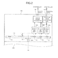
- FIG. 2 is a view for explaining a configuration of a rotary encoder according to the present embodiment.
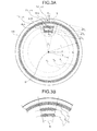
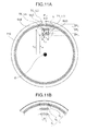
- FIG. 3A is a view for explaining a disk provided to the rotary encoder according to the present embodiment.
- the encoder 100 includes a rotating shaft 101, a disk 110, detecting units 130A to 130C, a position data generating unit 140, and an origin signal generating unit 141.
- the disk 110 is formed in a disk-shape and is arranged such that a disk center O is nearly coincident with the rotation axis AX.
- the disk 110 is connected to the rotating shaft 202 corresponding to the rotating shaft 201 of the motor unit 200 via the rotating shaft 101 that is rotatable about the rotation axis AX. Therefore, the disk 110 is arranged in a manner rotatable about the rotation axis AX in association with rotation of the motor unit 200.
- the disk 110 includes tracks TA to TC.
- the disk 110 includes the track TC for detecting the position x in rotation of the motor unit 200 and two tracks TA and TB for accurately detecting the origin z.
- the number of tracks T is not limited to three and is set in plurality as appropriate in accordance with detection accuracy and signal processing required for the origin z.
- the track TC is formed in a ring-shape on the whole circumference about the disk center O of the disk 110.
- the tracks TA and TB are formed in origin detection areas hA and hB of lengths in the circumferential direction with respect to a predetermined origin detection area reference angle H in an arc about the disk center O of the disk 110.
- origin detection areas hA to hC of the tracks TA to TC are also collectively referred to as an "origin detection area h".
- origin detection areas hA to hC of the tracks TA to TC are each formed within a range of a length in the circumferential direction with respect to the same origin detection area reference angle H in the present embodiment, the origin detection areas hA to hC may be formed with respect to different origin detection area reference angles H.
- the tracks TA to TC are formed in predetermined widths wA to wC, respectively.
- the tracks TA to TC are arranged such that the positions thereof at the center of the width w in the radial direction (track radii rA to rC) are different from one another.
- the tracks TA and TB are formed on concentric circles about the disk center O, and the tracks TA, TB, and TC are arranged from the disk center O toward the outer periphery in order of TA, TB, and TC (rA ⁇ rB ⁇ rC).
- Concentric measuring circles XA to XC based on the track radii rA to rC are also collectively referred to as a "measuring circle X".
- optical rotating gratings LA to LC rotating optical diffraction gratings are formed on the tracks TA to TC, respectively.
- the rotating gratings LA to LC include a plurality of optical slits SLA to SLC, respectively, and each form a part of an individual diffraction interference optical system independent of one another.
- the slits SLA to SLC are each formed in a manner reflecting light (a reflecting slit) or in a manner transmitting light (a transmitting slit). If a slit SL is formed as a reflecting slit, the slit SL may be formed by depositing a material having high reflectance, for example. By contrast, portions other than the slits SLA to SLC on the disk 110 may be formed by arranging a material that absorbs light with a method, such as vapor deposition, or using a material that transmits light for the disk 110 itself, for example.
- the slit SL can also be formed by using a material that reflects light for the disk 110 itself and processing the portions other than the slits SLA to SLC by etching, for example.
- the slits can be formed as phase diffraction gratings by forming both the slits SLA to SLC and the portions other than the slits SLA to STC with a material having high reflectance and providing differences in level in a gap direction between the slits SLA to SLC and the portions other than the slits SLA to SLC.
- the slit SL may be formed by forming the disk 110 itself with a material that transmits light and by arranging a material that absorbs or reflects light to block light or performing processing for blocking light on the portions other than the slits SLA to SLC, for example.
- the method for forming the slits SLA to SLC is not restricted in particular. In other words, if the slit SL is a reflecting slit, the slits SLA to SLC reflect light, and the portions other than the slits SLA and SLC do not reflect light.
- the slit SL is a transmitting slit, the slits SLA to SLC transmit light, and the portions other than the slits SLA and SLC block light.
- the slits SLA to SLC of the tracks TA to TC on the disk 110 are reflecting slits for convenience of description. If reflecting slits are used for the disk 110 in this manner, a reflective diffraction interference optical system can be formed. As a result, it is possible to reduce noise and influence on detection accuracy caused by fluctuation in a gap g between the disk 110 and a mask 120, which will be described later, compared with the case where transmitting slits are used for the disk 110.
- the area division numbers nA to nC of the origin detection areas hA to hC by the slits SLA to SLC arranged in the circumferential direction on the tracks TA to TC, respectively, are set to different numbers from one another.
- the area division numbers nA to nC correspond to the number of slits obtained by counting the number of slits SLA to SLC, respectively, along the circumferential direction (measuring circle X) in the origin detection area h. Therefore, the area division numbers nA to nC, that is, the numbers of slits arranged along the circumferential direction in the origin detection area h are set to different numbers from one another.
- the tracks TA to TC are preferably formed such that the area division numbers nA to nC in the origin detection area h increase as the track redii rA to rC increase.
- the area division numbers in the origin detection area h of the tracks TA to TC are set in a manner satisfying "nA ⁇ nB ⁇ nC".
- Three periodic signals corresponding to the area division numbers nA to nC are obtained from the tracks TA to TC. Therefore, the area division number nC in the origin detection area hC of the track TC is preferably set to a number corresponding to resolution required for detecting the position x with desired accuracy.
- the area division numbers nA and nB in the origin detection areas hA and hB of the tracks TA and TB are preferably set to numbers corresponding to resolution required for detecting the origin z with desired accuracy.
- Two or more pitches among pLA to pLC of the tracks TA to TC only need to be nearly the same, and a track having a different pitch may be included.
- the pitches pLA to pLC means an arrangement interval between adjacent slits in the slits SLA to SLC, respectively.
- the pitches pLA to pLC mean center-to-center distances of the slits.
- the slit SLC is formed on a radial line (a radial line LINE 1 illustrated in FIG. 7 ) set at an equiangular interval about the disk center O (rotation axis AX).
- the slit in this shape is also referred to as a "radial slit”.
- the slits SLA and SLB of the tracks TA and TB are formed as a "curved slit" different from the radial slit so as to adjust the pitches pLA to pLC of the tracks TA to TC to the pitch pL as described above and to facilitate downsizing and manufacturing and the like more significantly.
- the slit SLC of the track TC may also be formed as the curved slit.
- at least one of the tracks TA to TC may be formed as the curved slit. If the curved slit is included in this manner, it is possible to facilitate adjustment of the pitches pLA to pLC, downsizing, and manufacturing and the like as described above.
- the curved slit will be described later in detail.
- the pitches pLA to pLC of the radical slit and the curved slit in the present embodiment mean intervals (pitches) between slits at the centers of the widths wA to wC of the track T.
- the area division numbers nA to nC in the origin detection area h of the tracks TA to TC are set in a manner satisfying nA ⁇ nB ⁇ nC as described above.
- the periodic numbers of signals in the origin detection area h obtained from the tracks TA to TC correspond to the area division numbers nA to nC in the origin detection area h, respectively.
- the tracks TA and TB constitute a part of an example of an origin detection mechanism that detects the origin z.
- the track TC constitutes a part of an example of a Position detection mechanism that detects the position x.
- a TA track detection mechanism having the least signal periodic number obtained in the origin detection area h among the tracks TA to TC is also referred to as an "origin L (low) detection mechanism".
- a detection mechanism with the track TB can detect a larger signal periodic number in the origin detection area h than the origin L detection mechanism.
- the detection mechanism with the track TB is also referred to as an "origin H (high) detection mechanism”.
- a detection mechanism with the track TC can detect a still larger signal periodic number in the origin detection area h than the origin H detection mechanism.
- the detection mechanism with the track TC is also referred to as an "incremental detection mechanism".
- the incremental encoder 100 detects the position x by processing output from the incremental detection mechanism. Furthermore, the incremental encoder 100 detects the origin z by processing output from the origin L, the origin H, and the incremental detection mechanism.
- the origin L detection mechanism, the origin H detection mechanism, and the incremental detection mechanism are different from one another in the area division numbers nA to nC in the origin detection area h and the shapes of the slits.
- the origin L detection mechanism, the origin H detection mechanism, and the incremental detection mechanism have something in common in that each mechanism has an independent diffraction interference optical system and that each mechanism uses the diffraction interference optical system as an optimal detection principle, for example. Therefore, in the description below, the origin L detection mechanism, the origin H detection mechanism, and the incremental detection mechanism are also collectively referred to as an "optical detection mechanism".
- FIG. 4 to FIG. 6 are views for explaining the optical detection mechanism provided to the rotary encoder according to the present embodiment.
- a detecting unit 130A is arranged in a manner facing the track TA and constitutes the origin L detection mechanism together with the track TA.
- a detecting unit 130B is arranged in a manner facing the track TB and constitutes the origin H detection mechanism together with the track TB.
- a detecting unit 130C is arranged in a manner facing the track TC and constitutes the incremental detection mechanism together with the track TC. Furthermore, as described above, the track TB and the track TC have the slits only in the origin detection area h. Therefore, the detecting unit 130A to the detecting unit 130C are arranged at positions facing the origin detection area h simultaneously in one rotation of the disk 110. In the case of FIG. 3A , because the origin detection areas hA to hC are arranged in a line, the detecting units 130A to 130C corresponding thereto are arranged in a corresponding line.
- the optical detection mechanisms formed of the detecting units 130A to 130C have something in common in that each mechanism has an independent diffraction interference optical system, for example. For this reason, one optical detection mechanism will be described as an example with reference to FIG. 4 , and differences in the optical detection mechanisms will be additionally described individually.
- a detecting unit (the detecting units 130A to 130C), a track (the tracks TA to TC), and a rotating grating (the rotating gratings LA to LC) corresponding to the optical detection mechanism are also simply referred to as a "detecting unit 130", a “track T”, and a “rotating grating L”, respectively, and a slit (the slits SLA to SLC) included in the rotating grating L is also simply referred to as a "slit SL" as illustrated in FIG. 4 .
- a pitch (the pitches pLA to pLC) of the slit SL is also simply referred to as a "pitch pL”
- the area division number (the area division numbers nA to nC) on the measuring circle X in the origin detection area h is also simply referred to as an "area division number n”.
- the detecting unit 130 includes the mask 120, a light emitting unit 131, and a light receiving unit 132.
- the mask 120 is fixed and arranged in a manner facing the disk 110 with the gap g interposed therebetween.
- the mask 120 is formed with a material that blocks light and includes two optical fixed gratings G1 and G2 (fixed diffraction gratings) having a plurality of slits SG1 and SG2, respectively, that transmit light.
- the mask 120 transmits light through the slits SG1 and SG2 of the fixed gratings G1 and G2, and the fixed gratings G1 and G2 constitute a three-grating diffraction interference optical system together with the rotating grating L.
- the fixed grating G1 and the fixed grating G2 are formed on the single mask 120.
- the fixed grating G1 and the fixed grating G2 may be formed on different masks 120. If the fixed grating G1 and the fixed grating G2 are formed on different masks 120, the fixed grating G1 and the fixed grating G2 are preferably arranged such that a distance (gap g) between the fixed grating G1 and the rotating grating L is equal to a distance (gap g) between the rotating grating L and the fixed grating G2 on the same surface side of the disk 110.
- each gap g of both the fixed gratings G1 and G2 is made uniform. As a result, it is possible to reduce influence on the diffraction interference optical system caused by fluctuation in the gap g.
- the pitches pLA to pLC of the slits SLA to SLC of the tracks TA to TC are set nearly equal to one another to the pitch PL, the gaps g between the detecting units 130A to 130C and the tracks TA to TC, that is, the disk 110 can be set nearly equal to one another.
- the gap g between the rotating grating LA and the fixed gratings G1 and G2 corresponding thereto, the gap g between the rotating grating LB and the fixed gratings G1 and G2 corresponding thereto, and the gap g between the rotating grating LC and the fixed gratings G1 and G2 corresponding thereto can be set nearly equal to one another as illustrated in FIG. 2 .
- gaps g are set in this manner, diffraction interference optical systems corresponding to the gaps g can be designed and developed for the detecting units 130A to 130C in common, and adjustment of the gaps g in manufacturing can be performed simultaneously on the detecting units 130A to 130C. Thus, it is possible to facilitate manufacturing and the like. Because the gaps g of the detecting units 130A to 130C are set equal to one another in this manner, the masks 120 of the detecting units 130A to 130C illustrated in FIG. 4 can be formed integrally, or the detecting units 130A to 130C can be formed integrally. Thus, it is possible to further facilitate manufacturing and the like.
- the optical detection mechanism in which the gaps g are made uniform is preferably an optical detection mechanism in which the pitches pL of the tracks T are set equal to one another.
- the fixed gratings G1 and G2 will now be described while explaining the light emitting unit 131 and the light receiving unit 132.
- the light emitting unit 131 includes a light source and irradiates the fixed grating G1 of the mask 120 with light. While the wavelength and the intensity of the light output from the light emitting unit 131 is not particularly restricted, the wavelength and the intensity may be determined as appropriate in accordance with characteristics of the diffraction interference optical system, required position resolution, and the like. In the present embodiment, diffusion light is used as the irradiation light. By using diffusion light, the slits SG1 of the fixed grating G1, which will be described later, can be considered as an approximately linear light source, thereby enhancing a diffraction interference effect.
- the slit SG1 can be considered as an approximately linear light source in this manner, parallel light, laser light, convergent light, and the like can be used as the irradiation light.
- the light emitting unit 131 may include a predetermined optical element, such as a diffusing lens, in accordance with characteristics of light to be used, such as parallel light, laser light, convergent light, and diffusion light.
- the fixed grating G1 is formed at a position on which the light output from the light emitting element 131 is incident.
- the fixed grating G1 includes the transmitting slits SG1 and diffracts the incident light by the slits SG1.
- each of the slits SG1 can convert the light output to the disk 110 into light output from each of the slits SG1 serving as an approximately linear light source.
- a signal periodic number m obtained in the origin detection area h changes depending on the value i besides the area division number n.
- the width of the slit SL of the rotating grating L is preferably set larger than the width of the slit SG1 of the fixed grating G1 so as to improve the signal intensity in consideration of the spread angle.
- the width of the slit SL of the rotating grating L still larger or smaller than a width in which the light transmitted through the fixed grating G1 is expected to reach, it is possible to further improve the stability of a signal against an installation error between the fixed grating G1 and the rotating grating L.
- the width of the slit SG2 of the fixed grating G2 which will be described later, is preferably set larger than the width of the slit SL of the rotating grating L so as to improve the signal intensity in consideration of the spread angle.
- the width of the slit SL of the fixed grating G2 still larger or smaller than a width in which the light reflected by the rotating grating L is expected to reach, it is possible to further improve the stability of a signal against an installation error between the fixed grating G2 and the rotating grating L in the same manner. It goes without saying that the relationship among the widths of the slits of the fixed grating G1 the fixed grating G2, and the rotating grating L are not restricted in particular if sufficient signal intensity is ensured and the stability of a signal against an installation error is sufficiently ensured.
- the slits SG1 included in the fixed grating G1 are preferably formed in a manner nearly parallel to the slits SL formed at a facing position so as to enhance the diffraction interference effect of the diffraction interference optical system formed together with the rotating grating L and the fixed grating G2 and to reduce noise.
- the slits SLA and SLB of the rotating gratings LA and LB are curved slits
- the slits SG1 and SG2 of the rotating grating G1 of the detecting units 130A and 130B are preferably formed as curved slits in a manner parallel to facing curved slits.
- the slits S of the rotating grating LC are radial slits
- the slits SG1 and SG2 of the rotating grating G1 of the detecting unit 130C are preferably formed as radial slits in a manner parallel to facing radial slits.
- the pitch pL of the radial slits is short enough compared with the whole circumference of the track T to consider the radial slits as optically parallel slits. Therefore, the slits SG1 of the fixed grating G1 of the detecting unit 130C corresponding to the radial slits can be formed as "parallel slits" parallel to one another. Similarly, the slits SG1 of the fixed grating G1 of the detecting units 130A and 130B corresponding to the curved slits can be formed as parallel slits as illustrated in FIG. 5 .
- the parallel slits of the fixed grating G1 corresponding to the radial slits are preferably arranged in a manner parallel to the parallel slits obtained by considering the radial slits as the parallel slits. Furthermore, the parallel slits of the fixed grating G1 corresponding to the curved slits are preferably arranged in a manner nearly parallel to a tangent LINE 3 to each curved slit at one or more points as illustrated in FIG. 5 .
- both the fixed gratings G1 corresponding to the radial slits and the curved slits as parallel slits in this manner, an identical fixed grating G1 can be used for both the fixed gratings G1. As a result, it is possible to further facilitate manufacturing and the like and to reduce manufacturing cost.
- the light diffracted by the fixed grating G1 is output to the rotating grating L corresponding to the fixed grating G1.
- the light output to the rotating grating L is then reflected by the slit SL of the rotating grating L.
- the light thus reflected is further diffracted by the rotating grating L.
- the light diffracted by the rotating grating L is output to the fixed grating G2.
- the fixed grating G2 of the mask 120 used for the origin L detection mechanism and the origin H detection mechanism is formed at a position on which the light diffracted by the rotating grating L is incident.
- a pitch pG2 between the slits SG2 of the fixed grating G2 is set to equal to the pitch pG1 between the slits SG1 of the fixed grating G1.
- the shape of the slit SG2, the positional relationship with respect to the slit SG1 of the fixed grating G1, and other elements are the same as those of the slit SG2 of the fixed grating G1 described above. For this reason, detailed explanations thereof will be omitted.
- the light diffracted by the rotating grating L is output to the fixed grating G2.
- the light output to the fixed grating G2 forms interference fringes in which the light diffracted by each of the slits SL of the rotating grating L interferes.
- the position of bright bands in the interference fringes moves in response to a change in the positional relationship between the fixed grating G1 and the rotating grating L caused by rotation of the disk 100.
- the intensity of light passing through the slit SG2 increases sinusoidally.
- the light receiving unit 132 is arranged so as to receive the light transmitted through the slit SG2 of the fixed grating G2.
- the light receiving unit 132 includes a light receiving element, such as a photodiode, and converts the intensity of the light thus received into an electrical signal.
- the electrical signal generated by the light receiving unit 132 is an approximately sinusoidal electrical signal (also referred to as a "periodic signal”) at a predetermined period repeated every time the disk 110 moves by an amount corresponding to the pitch pL and the like.
- Periodic signals obtained in the origin L detection mechanism and the origin H detection mechanism are also collectively referred to as an "origin L signal” and an “origin, H signal”, respectively.
- the mask 120 (a mask 120C) used for the incremental detection mechanism has a different structure from those of the mask 120 (masks 120A and 120B) used for the origin L detection mechanism and the origin H detection mechanism, the explanation thereof will be made.
- the fixed grating G2 of the mask 120C is divided into two or more areas (e.g., areas G2A and G2B illustrated in FIG. 6 ).
- the slits SG2 of each area are formed with the uniform pitch pG2 therebetween in the areas.
- the pitch between the areas is formed by adding "pG2/4" to the pitch pG2.
- the intensity of light passing through the slits SG2 of the areas G2A and G2B shifted by "pG2/4" from each other increases sinusoidally in a manner shifting by 90 degrees.
- the light receiving unit 132 includes two light receiving surfaces, for example, such that the light receiving unit 132 can generate different electrical signals for the areas G2A and G2B.
- the periodic signals each corresponding to the areas G2A and G2B are two periodic signals out of phase with each other by 90 degrees.
- the two periodic signals are also referred to as an "A-phase periodic signal” and a "B-phase periodic signal”.
- the two periodic signals obtained in the incremental detection mechanism are also collectively referred to as an "incremental signal”.
- each of the origin L signal and the origin H signal are one periodic signal, and the incremental signal is two periodic signals.
- the optical detection mechanism is formed of a three-grating diffraction interference optical system. Therefore, if interference occurs in the relationship among the pitches pL, pG1, pG2, and the like regardless of the size of the gap g, it is possible to detect a desired periodic signal.
- a geometrical optical encoder simply receives light transmitted through the slit SL. Therefore, as the gap g is made larger, noise increases because of influences of light in a diffraction component and a diffusion component. To address this, the gap g needs to be made smaller.
- the gap between a fixed member and a rotating member can be made larger. As a result, it is possible to increase flexibility in designing and development and to reduce trouble in that the fixed member and the rotating member interfere with each other because of an impact and the like.
- a three-grating (the rotating grating L and the fixed gratings G1 and G2) diffraction interference optical system is explained as an example in the present embodiment, the present invention is not limited thereto.
- a pseudo three-grating diffraction interference optical system can be formed.
- a pseudo three-grating diffraction interference optical system can also be formed. It goes without saying that the number of gratings is not restricted in particular as long as it is possible to form a similar three-grating diffraction interference optical system.
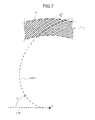
- FIG. 7 is a view for explaining the curved slit provided to the rotary encoder according to the present embodiment.
- One of the curved slits that is, the slit SLA of the rotating grating LA on the track TA or the slit SLB of the rotating grating LB on the track TB will now be described as an example with reference to FIG. 7 . Differences between the slit SLA and the slit SLB will be described individually.
- the slit SL of the rotating grating L is arranged on the track T, the slit SL of one or more rotating gratings L is formed as a curved slit different from a radial slit as described above and illustrated in FIG. 7 .
- the slit SL formed as a curved slit (simply referred to as the "slit SL") is formed along a curved line LINE 2 obtained by curving a radial line LINE 1 about the disk center O (rotation axis AX) in the circumferential direction at predetermined curvature C.
- the radial line LINE 1 corresponding to each slit SL is set for the number of slits corresponding to the area division number n to be set in the origin detection area h of the track T and at every angle obtained by equiangularly dividing the origin detection area reference angle H. Subsequently, each radial line LINE 1 is curved at the same curvature C in the same circumferential direction to be positioned at the origin detection area h, whereby the curved line LINE 2 for each of the slits SL is set. Each of the slits SL is then formed with a predetermined width along the curved line LINE 2 thus set.
- the disk center O is determined to be the origin
- 1 represents a distance from the origin
- ⁇ represents an angle with respect to a reference line passing through the origin
- rIN and rOUT represent an inner diameter and an outer diameter, respectively, of the track T in which the origin detection area h is set
- H° represents an origin detection area reference angle in the origin detection area h.
- the radial line LINE 1 is expressed in polar coordinates by Equation 1.
- LINE 1 l , j ⁇ H / n where rIN ⁇ l ⁇ rOUT is satisfied.
- the curved line LINE 2 is expressed in polar coordinates by Equation 2.
- LINE 2 r ⁇ 0 ⁇ 1 - c ⁇ , ⁇ + j ⁇ H / n where rIN ⁇ r0(1-C ⁇ ) ⁇ rOUT is satisfied.
- r0 represents a radius at which the pitch of the slits SL of the rotating grating L is a desired pL.
- the curvature C is expressed by Equation 3.
- C tan sin - l pL ⁇ n / 2 ⁇ ⁇ r ⁇ 0
- w tan sin - l pL ⁇ n / 2 ⁇ ⁇ r ⁇ 0
- the slit SL serving as the curved slit reaches from a position on the track inner diameter (rIN) to a position on the track outer diameter (rOUT) at the angle ⁇ within 180°.
- Each one of the curved slits SL is formed at the angle ⁇ within 180° so as not to make a circuit of the track T. Forming the curved slit in this manner makes it possible to increase the strength of the disk 110 and to facilitate formation of the slit SL.
- the pitch of the slits SL included in the rotating grating L is formed more uniform regardless of the position of the slits SL in the longitudinal direction, noise in the sinusoidal periodic signal thus obtained can be reduced, and the position detection accuracy can be improved.
- the increasing rate and the decreasing rate of a shift amount from the pitch pL with respect to movement from the center of the width w of the track T to the track inner diameter or the track outer diameter along the slit SL are reduced, noise can be suppressed, and the detection accuracy can be improved.
- the slit SL is formed in a curved manner, whereby it is possible to reduce a change amount of the pitch (also referred to as a "change rate of the patch") of the slit SL in the direction of formation of the slit SL (the direction of the curved line LINE 2).
- the encoder 100 according to the present embodiment can improve the detection accuracy for the periodic signal obtained from each optical detection mechanism and improve the origin detection accuracy.
- the slit SL is a radial slit
- the slit SL is formed on the radial line LINE 1. Because the length in the direction of formation of the slit SL (radial line LINE 1) is nearly equal to the width w of the track T, the change rate of the pitch of the slit SL in the direction of formation is relatively high. The relatively high change rate of the pitch causes reduction in the detection accuracy for the periodic signal. The reduction in the detection accuracy is made larger as the area division number n is smaller.
- the slit SL is a curved slit
- the length in the direction of formation of the slit SL (curved line LINE 2) can be extended by the length corresponding to the curvature C compared with the radial slit.
- the encoder 100 can set the tracks TA to TC from which different signal periodic numbers m are obtained without reducing the flexibility in designing, development, and the like or reducing the detection accuracy for the periodic signal. Consecutively, according to the present embodiment, it is possible to facilitate formation of the highly accurate and small encoder 100.
- the optimum gap g between the rotating grating L and the fixed gratings G1 and G2 depends on a wavelength ⁇ of the light output from the light emitting element 131 and on the pitch pL of the slits SL of the rotating grating L.
- k represents a positive integer
- the curvature C it is possible to set the pitch pL to the optimum value at which a diffraction interference optical system is formed without changing the area division number n (corresponding to the period of the periodic signal) or the track radius r.
- the area division number n, the track radius r, and other elements can be set optionally, whereby it is possible to facilitate downsizing, designing, development, and the like.
- the slit SL is formed in a manner circling one or more times in the track T unlike the present embodiment, such a slit is also referred to as a "multiple spiral slit".
- a multiple spiral slit the number of slits SL layered in the radial direction increases and the width w of the track T increases, thereby making it difficult to achieve downsizing.
- the flexibility in designing and development is reduced, resulting in difficulties in manufacturing.
- the slit SL according to the present embodiment is not a multiple spiral slit but a curved slit. As a result, as described above, it is possible to increase the flexibility in designing and development and to facilitate manufacturing and downsizing.
- Equations of the curved line LINE 2 are given just as an example, and Equations described above need not be actually calculated.
- the formation method, the design method, and other methods are not restricted in particular.
- the fixed gratings G1 and G2 are arranged such that each of the slits SG1 and SG2 is parallel to the tangent LINE 3 to the curved line LINE 2 of the slit SL of the rotating grating L corresponding thereto as illustrated in FIG. 5 .
- the curved slit according to the present embodiment even if the arrangement position of the fixed gratings G1 and G2 shifts slightly, the area in which the fixed gratings G1 and G2 serving as parallel slits are parallel to the rotating grating L can be considerably secured because the change amount of the pitch pL of the curved slit is relatively small. As a result, it is possible to further improve the detection accuracy for the periodic signal and to facilitate manufacturing and the like significantly.
- the gaps g between the rotating gratings LA to LC of all the tracks TA to TC and the masks 120 of the detecting units 130A to 130C corresponding to the rotating gratings LA to LC, respectively, are set nearly equal to one another.
- the curvature C in the slit SLA of the track TA is set such that the pitch pLA of the slit SLA is equal to the pitch pLC of the slit SLC of the track TC serving as a track other than the track TA. Furthermore, as illustrated in FIG. 3A , the curvature C in the slit SLB of the track TB is set such that the pitch pLB of the slit SLB is equal to the pitch pLC of the slit SLC of the track TC serving as a track other than the track TB.
- the area division number nA in the origin detection area hA of the track TA is different from the area division number nB in the origin detection area hB of the track TB. Therefore, as is clear from Equation 3, the curvature C in the track TA is set different from the curvature C in the track TB.
- the pitch pLA in the track TA and the pitch pLB in the track TB which are curved slits, can be set nearly equal to each other.
- the detecting units 130A to 130C can be arranged with the uniform gap g while forming the diffraction interference optical system. If the detecting units 130A to 130C can be formed with the uniform gap g in this manner, it is possible to facilitate adjustment of the detecting units 130A to 130C in the gap g direction and to form the detecting units 130A to 130C integrally. If the detecting units 130A to 130C are formed integrally, the masks 120 provided to each of the detecting units may be formed integrally as a single mask. In this case, it is possible to increase the flexibility in designing and the like and to facilitate manufacturing.
- the position data generating unit 140 included in the encoder 100 will now be described with reference to FIG. 2 .
- the position data generating unit 140 acquires a sinusoidal incremental signal from the detecting unit 130C.
- the position data generating unit 140 specifies the position x of the motor unit 200 from the signal and outputs position data indicating the position x.
- An example of the specification processing of the position x performed by the position data generating unit 140 will now be described more specifically.
- the incremental signal acquired by the position data generating unit 140 includes two periodic signals of the A-phase periodic signal and the B-phase periodic signal out of phase with each other by 90 degrees.
- the position data generating unit 140 acquires two sinusoidal signals of the A phase and the B phase as the incremental signal.
- the position data generating unit 140 then performs multiplication processing and the like on the incremental signal, thereby converting the two sinusoidal signals of the A phase and the B phase into a signal monotonically increasing in a period (alternatively, it may be a signal monotonically decreasing. Hereinafter, it is also referred to as a "monotonically increasing signal").
- the position data generating unit 140 specifies the position x of the motor unit 200 based on the incremental signal.
- the processing performed by the position data generating unit 140 may be performed by the controller 20.
- the position data generating unit 140 may output each sinusoidal periodic signal to the controller 20 as position data.
- FIG. 8A to FIG. 8C are views for explaining the origin signal generating unit provided to the rotary encoder according to the present embodiment.
- the origin signal generating unit 141 acquires a sinusoidal origin L signal, a sinusoidal origin H signal, and a sinusoidal incremental signal from the detecting units 130A to 130C. The origin signal generating unit 141 then specifies the origin z of the motor unit 200 from these signals and outputs an origin signal indicating the origin z. An example of the specification processing of the origin z performed by the origin signal generating unit 141 will now be described more specifically.
- the incremental signal acquired by the origin signal generating unit 141 includes two periodic signals of the A-phase periodic signal and the B-phase periodic signal out of phase with each other by 90 degrees.
- the origin signal generating unit 141 acquires two sinusoidal signals of the A phase and the B phase as the incremental signal.
- the origin signal generating unit 141 uses one of the two sinusoidal signals of the A phase and the B phase to perform processing. An assumption is made that the origin signal generating unit 141 uses the A phase, for example.
- the A-phase signal of the incremental signal is also simply referred to as an "incremental A signal”.
- FIG. 8A illustrates an example of the origin L signal
- FIG. 8B illustrates an example of the origin H signal
- FIG. 8C illustrates an example of the incremental A signal
- FIG. 8D illustrates an example of the origin signal.
- the horizontal axis represents mechanical angles (angle ⁇ )
- the vertical axis represents each signal V.
- Output signals of the origin L signal, the origin H signal, and the incremental signal are also referred to as "VA”, "VB”, and "VC", respectively.
- FIG. 8A illustrates an example of the signal VA obtained when the rotating disk 110 rotates by a predetermined angle equal to or smaller than the origin detection area reference angle H, that is, when passing through the origin detection area h, as the origin L signal.
- FIG. 8B illustrates an example of the signal VB obtained when the rotating disk 110 rotates by a predetermined angle equal to or smaller than the origin detection area reference angle H, that is, when passing through the origin detection area h, as the origin H signal.
- FIG. 8C illustrates an example of the signal VC obtained when the rotating disk 110 rotates by a predetermined angle equal to or smaller than the origin detection area reference angle H, that is, when passing through the origin detection area h, as the incremental A signal.
- FIG. 8D illustrates an example where the output signals VA, VB, and VC are added when the rotating disk 110 rotates by the origin detection area reference angle H, that is, when passing through the origin detection area h, as the origin signal.
- the area division numbers n of the origin L signal, the origin H signal, and the incremental signal are set to odd multiples of 1, 3, and 5, respectively, and each signal outputs a sine wave of the number of periods corresponding thereto.
- the area division numbers nA to nC in the origin detection area h repeated in the measuring circle X of the tracks TA to TC are set to 1, 3, and 5, respectively, to realize such a resolution.
- the area division numbers nA to nC of the tracks TA to TC may be set as appropriate in accordance with a desired signal periodic number for the periodic signal obtained therefrom,
- the origin signal generating unit 141 generates the origin L signal, the origin H signal, and the incremental A signal, and specifies the origin z of the motor unit 200 based on these signals.
- the slits SLA to SLC of the tracks TA to TC are arranged such that peaks of a plurality of periodic signals coincide with one another only at one point in one rotation of the disk 110, and the origin signal generating unit 141 adds three signals of the origin L signal, the origin H signal, and the incremental A signal.
- the signal thus added forms a peak at a position where the peaks of the periodic signals coincide with one another. Therefore, the origin signal generating unit 141 generates an origin signal V z from the peak formation position of the added signal.
- the origin signal generating unit 141 uses a comparison device, such as a comparator, to convert the added signal into a digital signal by a predetermined threshold capable of extracting only the peak of the added signal.
- a comparison device such as a comparator
- the origin signal generating unit 141 generates a square wave indicating the origin position, that is, an origin pulse signal indicating the origin z as the origin signal V z .
- the origin signal generating unit 141 can specify the origin z of the motor unit 200 with resolution similar to the resolution of the outermost incremental detection mechanism.
- the origin signal generating unit 141 then outputs the origin signal indicating the origin z thus specified to the controller 20.
- the processing performed by the origin signal generating unit 141 may be performed by the controller 20.
- the origin signal generating unit 141 may output each sinusoidal periodic signal to the controller 20 as an origin signal.
- the controller 20 acquires a higher-level control signal from a higher-level control device or the like and acquires position data indicating the position x of the motor unit 200 and a origin signal indicating the origin z from the encoder 100. The controller 20 then generates a control signal based on the higher-level control signal, the position data, and the origin signal, and outputs the control signal to the motor unit 200.
- the motor unit 200 rotates the rotating shaft 201 based on the control signal.
- the disk 110 of the encoder 100 connected to the rotating shaft 202 corresponding to the rotating shaft 201 via the rotating shaft 101 is rotated.
- the detecting units 130A to 130C each detect a signal in response to the rotation of the disk 110 and output the signal to the position data generating unit 140 and the origin signal generating unit 141.
- the position data generating unit 140 and the origin signal generating unit 141 generate position data and an origin signal based on these signals thus acquired, respectively, and output the position data and the origin signal to the controller 20.
- the encoder 100 can detect the highly accurate position x and the origin z of the motor unit 200 and supply the position x and the origin z to the controller 20 as position data and an origin signal. Therefore, the motor system 1 can control the position x of the motor unit 200 with high accuracy based on the highly accurate position x and the origin z.
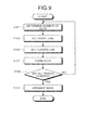
- FIG. 9 is a flowchart for explaining a method for manufacturing the rotary encoder according to the present embodiment. In the description below, a method for producing a curved slit will be mainly explained.
- Step S101 an example of a slit number determination step
- a desired signal periodic number to be acquired in the origin detection area h of one track T of the disk 110, which is a curved slit is determined.
- the area division number n that is, the number of slits along the measuring circle X formed in the origin detection area h is determined.
- the system control goes to Step S103.
- Step S103 an example of a radial line setting step
- the radial lines LINE 1 of the number determined at Step S101 are set equiangularly within the origin detection area reference angle H of the origin detection area h about the disk center O (rotation axis AX) as illustrated in FIG. 7 . Subsequently, the system control goes to Step S105.
- Step S105 an example of a curved line setting step
- the curvature C is set such that the pitch pL of the silt SL is a desired value.
- the radial lines LINE 1 set at Step S103 are curved at the same curvature C thus set in the same circumferential direction, whereby a plurality of curved lines LINE 2 are set.
- the setting positions of the radial lines LINE 1 are determined at Step S103 such that the curved lines LINE 2 are included in the origin detection area h.
- the curvature C is set to 0 (indicating that the lines are not curved) at Step S105.
- the curvature C is set such that the pitch pL of the slit SL of the track T (an example of one track) to be formed is equal to the pitch pL of the slit SL of the track T that has already been formed or the track T to be formed subsequently (an example of another track T).
- the system control goes to Step S107.
- Step S107 an example of a slit formation step
- a plurality of slits SL are formed in the origin detection area h with a predetermined width w along the curved lines LINE 2 set at Step S105. Subsequently, the system control goes to Step S109.
- Step S109 it is determined whether the slit SL is formed in all the desired origin detection areas h (or the tracks T). If there is an origin detection area h (or a track T) in which no slit SL is formed yet, the system control is returned to Step S101. By contrast, if all the slits SL are formed, the system control goes to Step S111.
- Step S111 an example of a mask arrangement step
- the detecting unit 130 including the mask 120 is arranged for two or more tracks T and origin detection areas h having at least the same pitch pL such that the gaps g between the rotating grating L and the fixed gratings G1 and G2 are equal to one another.
- processing for connecting the rotating shaft 101 to the disk 110 processing for connecting each detecting unit 130 to the position data generating unit 140 and the origin signal generating unit 141, processing for housing each component in a case in a manner fixed or supported rotatably, and other processing are performed, thereby completing the encoder 100.
- processing for connecting the rotating shaft 101 to the disk 110 processing for connecting each detecting unit 130 to the position data generating unit 140 and the origin signal generating unit 141, processing for housing each component in a case in a manner fixed or supported rotatably, and other processing are performed, thereby completing the encoder 100.
- processing for connecting the rotating shaft 101 to the disk 110 processing for connecting each detecting unit 130 to the position data generating unit 140 and the origin signal generating unit 141, processing for housing each component in a case in a manner fixed or supported rotatably, and other processing are performed, thereby completing the encoder 100.
- detailed explanations of these processing will be omitted.
- the slits SL in at least one origin detection area h are formed as curved slits along the curved lines LINE 2.
- the pitch pL can be adjusted with the area division number n fixed to a desired value by adjusting the curvature C of the curved line LINE 2. Therefore, it is possible to improve the flexibility in designing, development, and the like.
- the length of every slit SL can be extended by the length corresponding to the curvature C.
- the encoder 100 according to the present embodiment uses the diffraction interference optical system with the curved slit.
- the encoder 100 uses the curved slits to make the slits SL more similar to parallel slits, it is possible to improve the S/N ratio of the detection signal and other elements and to improve the detection accuracy.
- the encoder 100 it is possible to improve the detection accuracy using diffraction interference light.
- the diffraction interference optical system can be designed and developed such that restrictions are reduced in designing and developing of the diffraction interference optical system to facilitate manufacturing thereof, for example.
- the present embodiment is applied to the incremental encoder 100 as in the present embodiment, by using the curved slit in one or more origin detection areas h, it is possible to make the pitches pL in two or more origin detection areas h or tracks T equal to one another. As a result, it is possible to make the gaps g between the detecting units 130 (that is, the masks 120) and the origin detection areas h or the tracks T equal to one another. Therefore, a nearly identical diffraction interference optical system can be designed and developed for the origin detection areas h and the tracks T, for example. In addition, the gaps g for the detecting units 130 corresponding to the origin detection areas h and the tracks T can be adjusted simultaneously. Therefore, it is possible to significantly facilitate designing, development, and manufacturing, for example.
- FIG. 10A is a view for explaining a structure of a disk provided to a rotary encoder according to the second embodiment of the present invention.
- the explanation has been made of the case where the tracks TA and TB formed as curved slits have different track radii r (rA ⁇ rB) as illustrated in FIG. 3A .
- the present invention is not limited to the example, and the track radii r of the tracks TA and TB can be equal to each other.
- an explanation will be made of the case where the track radii r of the tracks TA and TB are formed equal to each other.
- the encoder and other components according to the present embodiment can be configured in the same manner as in the first embodiment other than that the track radii r of the tracks TA and TB are formed equal to each other. For this reason, differences from the first embodiment will be mainly explained.
- a disk 610 provided to the encoder according to the present embodiment includes a track TA and a track TB similarly to the first embodiment.
- the formation positions of the track TA and the track TB are different from the positions illustrated in FIG. 3A .
- the track TA and the track TB are formed at positions adjacent to each other in the circumferential direction on the same track radius rD.
- the tracks are formed in the radial direction as illustrated in FIG. 3A , the area of the tracks in the radial direction of the disk increases in accordance with the track width and the track number, whereby designing and development of the disk shape may be restricted.
- FIG. 11A is a view for explaining a structure of a disk provided to a rotary encoder according to the third embodiment of the present invention.
- the explanations have been made of the case where curved slits are used for the slits SLA and SLB of the tracks TA and TB as an origin detection mechanism. Because the origin detection mechanism only needs to be capable of detecting an origin signal with accuracy obtained by a specified slit pitch, the slits SLA and SLB are not limited to curved slits.
- the third embodiment of the present invention an explanation will be made of the case where inclined slits are used instead of the curved slits.
- the components other than the slits SLA and SLB can be configured in the same manner as in the first embodiment or the second embodiment. For this reason, differences from the first and the second embodiments will be mainly explained.
- a disk 710 provided to the encoder according to the present embodiment includes tracks TD and TE instead of the tracks TA and TB illustrated in FIG. 3A .
- the tracks TD and TE are formed in a band shape as illustrated in FIG. 11 .
- origin detection areas h in the tracks TD and TE are set to the same width IDE in the circumferential direction, the origin detection areas h may have different widths.
- the tracks TD, TE, and TC are arranged such that positions at the center of the widths w in the radial direction (track radii rDD, rEE, and rC) are different from one another.
- the tracks TD, TE, and TC are arranged from the disk center O toward the outer periphery in order of TD, TE, and TC (rDD ⁇ rEE ⁇ rC).
- the tracks TD and TE have rotating gratings LD and LE including a plurality of inclined slits SLD and SLE, respectively.
- the inclined slits SLD and SLE are formed with slit pitches pLD and pLE, respectively.
- the numbers of inclined slits SLD and SLE are set so as to obtain a periodic signal of the periodic number capable of detecting an origin in the same manner as in the first embodiment and the like.
- the inclination angles (degrees) of the inclined slits SLD and SLE are set such that slits of the number described above are formed in the origin detection area h and that the pitch pLC is set to the value described above. In FIG.
- the number of inclined slits PLE is larger than the number of inclined slits PLD.
- the inclined slit PLE is formed in a manner inclined with respect to a radial line at an inclination angle smaller than that of the inclined slit PLD.
- two diffraction interference optical systems according to the present embodiment can also detect the origin L signal and the origin H signal described in the first embodiment. It goes without saying that the present embodiment can also provide other special advantageous effects and the like provided by the first embodiment.
- the inclined slit according to the present embodiment is formed in nearly the same manner as in the method for producing the curved slit illustrated in FIG. 9 . However, because processing at Step S105 is different, the processing at Step S105 will be described.
- an inclination angle is set such that the pitch pL of the inclined slit is a desired value in accordance with the number of slits SL at Step S105.
- the inclination angle is set such that the pitch pL of the slit SL in the origin detection area h to be formed is equal to the pitch pL of the slit SL of the origin detection area h or the track T that has already been formed or to be formed subsequently (an example of another track T).
- the track is formed by the simple inclined slit without using the curved slit, designing and development of the disk are facilitated compared with the encoders and the like according to the first and the second embodiment.
- FIG. 12A is a view for explaining a structure of a disk provided to a rotary encoder according to the fourth embodiment of the present invention.
- the explanation has been made of the case where directions to curve the slits SLA and SLB of the tracks TA and TB formed as curved slits are the same circumferential direction as illustrated in FIG. 3A .
- the present invention is not limited to the example, and the curve directions of adjacent tracks (that is, origin detection areas) may be set opposite to each other in the circumferential direction.
- the curve directions of adjacent tracks that is, origin detection areas
- an explanation will be made of the case where the curve directions of adjacent tracks are set opposite to each other in the circumferential direction.
- the encoder and other components according to the present embodiment can be configured in the same manner as in the first embodiment other than that the curve directions of the tracks are set opposite to each other in the circumferential direction. For this reason, differences from the first embodiment will be mainly explained.
- a disk 810 provided to the encoder according to the present embodiment includes a rotating grating LF instead of the rotating grating LB illustrated in FIG. 3A on a track TB (an example of at least one track).
- the rotating grating LF includes a plurality of slits SLF.
- the curve direction of the slit SLF is set opposite to the curve direction of a slit SLA of an adjacent track TA (an example of another track) in the circumferential direction.
- the slit SLA is formed along a curved line LINE 2 obtained by curving a radial line LINE 1 in the clockwise direction
- the slit SLF is formed along a curved line obtained by curving the radial line LINE 1 in the anticlockwise direction.
- Diffraction interference light output from the slits SL forms interference fringes repeating in a direction nearly perpendicular to the longitudinal direction of the slits SL.
- the longitudinal direction of the slit SL serving as a curved slit comes closer to the circumferential direction from the radial direction of the disk by being curved. Therefore, the interference fringes may possibly be formed in a manner repeating in a direction of an adjacent track. As a result, crosstalk may possibly occur between the interference fringes and a diffraction interference optical system of the adjacent track. To prevent crosstalk, designing and development of the encoder may possibly be restricted.
Landscapes
- Physics & Mathematics (AREA)
- General Physics & Mathematics (AREA)
- Engineering & Computer Science (AREA)
- Automation & Control Theory (AREA)
- Optical Transform (AREA)
Applications Claiming Priority (2)
| Application Number | Priority Date | Filing Date | Title |
|---|---|---|---|
| JP2010124762 | 2010-05-31 | ||
| PCT/JP2011/051198 WO2011152076A1 (fr) | 2010-05-31 | 2011-01-24 | Encodeur rotatif, moteur rotatif et système à moteur rotatif |
Publications (2)
| Publication Number | Publication Date |
|---|---|
| EP2579005A1 true EP2579005A1 (fr) | 2013-04-10 |
| EP2579005A4 EP2579005A4 (fr) | 2013-10-23 |
Family
ID=45066465
Family Applications (1)
| Application Number | Title | Priority Date | Filing Date |
|---|---|---|---|
| EP11789488.1A Withdrawn EP2579005A4 (fr) | 2010-05-31 | 2011-01-24 | Encodeur rotatif, moteur rotatif et système à moteur rotatif |
Country Status (5)
| Country | Link |
|---|---|
| US (1) | US8461790B2 (fr) |
| EP (1) | EP2579005A4 (fr) |
| JP (1) | JP5545366B2 (fr) |
| CN (1) | CN102918363B (fr) |
| WO (1) | WO2011152076A1 (fr) |
Families Citing this family (12)
| Publication number | Priority date | Publication date | Assignee | Title |
|---|---|---|---|---|
| EP2613128A4 (fr) * | 2010-09-02 | 2014-10-08 | Yaskawa Denki Seisakusho Kk | Codeur, servomoteur et unité motrice |
| CN104718434A (zh) * | 2013-03-11 | 2015-06-17 | 株式会社安川电机 | 编码器、带编码器的电机及伺服系统 |
| JP2015200613A (ja) * | 2014-04-10 | 2015-11-12 | 株式会社安川電機 | エンコーダ、エンコーダ付きモータ、サーボシステム |
| JP6359938B2 (ja) * | 2014-10-08 | 2018-07-18 | 株式会社トプコン | インクリメンタルエンコーダの読み取り信号の内挿方法 |
| WO2016143039A1 (fr) * | 2015-03-09 | 2016-09-15 | 富士機械製造株式会社 | Dispositif de détection et robot de soins infirmiers |
| CN105288869B (zh) * | 2015-10-26 | 2018-06-08 | 深圳市奥沃医学新技术发展有限公司 | 一种用于放疗设备旋转的控制装置和方法 |
| US11000698B2 (en) | 2015-10-26 | 2021-05-11 | Shenzhen Our New Medical Technologies Development Co., Ltd. | Device and method for controlling rotation of radiotherapy equipment |
| CN108571992B (zh) * | 2017-03-09 | 2020-04-21 | 曾吉旺 | 光学扫描式双层导光编码器 |
| WO2020188668A1 (fr) * | 2019-03-15 | 2020-09-24 | 株式会社ハーモニック・ドライブ・システムズ | Codeur rotatif optique, servomoteur et actionneur |
| WO2020215205A1 (fr) * | 2019-04-23 | 2020-10-29 | 大族激光科技产业集团股份有限公司 | Disque de réseau et système de rétroaction |
| US11221238B2 (en) | 2019-07-05 | 2022-01-11 | Canon Kabushiki Kaisha | Optical encoder and drive control device comprising a light receiving element to receive a first interference fringe formed by a first periodic pattern and a second diffracted light from a second periodic pattern toward the first periodic pattern |
| WO2023035476A1 (fr) * | 2021-09-09 | 2023-03-16 | 深圳市汇顶科技股份有限公司 | Codeur optique et dispositif électronique |
Citations (4)
| Publication number | Priority date | Publication date | Assignee | Title |
|---|---|---|---|---|
| DE3807011C1 (fr) * | 1988-03-04 | 1989-04-27 | Dr. Johannes Heidenhain Gmbh, 8225 Traunreut, De | |
| DE19923505A1 (de) * | 1998-08-01 | 2000-02-03 | Heidenhain Gmbh Dr Johannes | Rotatorische Positionsmeßeinrichtung |
| US20080087805A1 (en) * | 2006-10-16 | 2008-04-17 | Kress Bernard C | Optical encoder with encoder member having one or more digital diffractive optic regions |
| US20090321621A1 (en) * | 2006-03-20 | 2009-12-31 | Kabushiki Kaisha Yaskawa Denki | Optical encoder |
Family Cites Families (14)
| Publication number | Priority date | Publication date | Assignee | Title |
|---|---|---|---|---|
| JPS6472020A (en) * | 1987-05-11 | 1989-03-16 | Honda Motor Co Ltd | Angular displacement detecting device |
| EP0639259B1 (fr) | 1992-05-05 | 1999-07-28 | MicroE, Inc. | Appareil de detection de mouvement relatif |
| US5537210A (en) | 1993-06-10 | 1996-07-16 | Canon Kabushiki Kaisha | Rotation detecting apparatus and scale having a multi helix diffraction grating for the same |
| JPH06347293A (ja) | 1993-06-10 | 1994-12-20 | Canon Inc | 回転検出装置及び回転検出用のスケール |
| JP3158878B2 (ja) * | 1994-07-28 | 2001-04-23 | 松下電器産業株式会社 | 光学式エンコーダ |
| JP3509830B2 (ja) | 1995-11-08 | 2004-03-22 | 株式会社安川電機 | 光学式ロータリエンコーダ |
| JP3213552B2 (ja) * | 1996-09-10 | 2001-10-02 | 株式会社リコー | エンコーダの原点位置検出装置 |
| ATE229642T1 (de) * | 1997-08-07 | 2002-12-15 | Heidenhain Gmbh Dr Johannes | Abtasteinheit für eine optische positionsmesseinrichtung |
| DE10217726A1 (de) * | 2002-04-17 | 2003-11-27 | Heidenhain Gmbh Dr Johannes | Optische Positionsmesseinrichtung |
| DE602005002287T2 (de) * | 2004-03-17 | 2008-05-29 | Canon K.K. | Optischer Encoder |
| JP2006153597A (ja) * | 2004-11-26 | 2006-06-15 | Nidec Copal Corp | 光学式エンコーダ |
| JP4724496B2 (ja) * | 2005-08-29 | 2011-07-13 | キヤノン株式会社 | 光学式エンコーダ |
| US7973941B2 (en) * | 2007-07-24 | 2011-07-05 | Mitutoyo Corporation | Reference signal generating configuration for an interferometric miniature grating encoder readhead using fiber optic receiver channels |
| EP2233892B1 (fr) * | 2009-03-27 | 2015-05-27 | SICK STEGMANN GmbH | Capteur de rotation à réseau cylindrique |
-
2011
- 2011-01-24 WO PCT/JP2011/051198 patent/WO2011152076A1/fr active Application Filing
- 2011-01-24 CN CN201180026694.0A patent/CN102918363B/zh not_active Expired - Fee Related
- 2011-01-24 JP JP2012518267A patent/JP5545366B2/ja not_active Expired - Fee Related
- 2011-01-24 EP EP11789488.1A patent/EP2579005A4/fr not_active Withdrawn
-
2012
- 2012-11-21 US US13/682,738 patent/US8461790B2/en not_active Expired - Fee Related
Patent Citations (4)
| Publication number | Priority date | Publication date | Assignee | Title |
|---|---|---|---|---|
| DE3807011C1 (fr) * | 1988-03-04 | 1989-04-27 | Dr. Johannes Heidenhain Gmbh, 8225 Traunreut, De | |
| DE19923505A1 (de) * | 1998-08-01 | 2000-02-03 | Heidenhain Gmbh Dr Johannes | Rotatorische Positionsmeßeinrichtung |
| US20090321621A1 (en) * | 2006-03-20 | 2009-12-31 | Kabushiki Kaisha Yaskawa Denki | Optical encoder |
| US20080087805A1 (en) * | 2006-10-16 | 2008-04-17 | Kress Bernard C | Optical encoder with encoder member having one or more digital diffractive optic regions |
Non-Patent Citations (1)
| Title |
|---|
| See also references of WO2011152076A1 * |
Also Published As
| Publication number | Publication date |
|---|---|
| JP5545366B2 (ja) | 2014-07-09 |
| EP2579005A4 (fr) | 2013-10-23 |
| CN102918363B (zh) | 2015-05-20 |
| JPWO2011152076A1 (ja) | 2013-07-25 |
| US8461790B2 (en) | 2013-06-11 |
| WO2011152076A1 (fr) | 2011-12-08 |
| US20130076289A1 (en) | 2013-03-28 |
| CN102918363A (zh) | 2013-02-06 |
Similar Documents
| Publication | Publication Date | Title |
|---|---|---|
| US8461790B2 (en) | Rotary encoder, rotary motor, and rotary motor system | |
| JP5170046B2 (ja) | ロータリエンコーダ、ロータリモータ、ロータリモータシステム、ディスク及びロータリエンコーダの製造方法 | |
| US8445835B2 (en) | Encoder, servo unit and encoder manufacturing method | |
| JP5170045B2 (ja) | リニアエンコーダ、リニアモータ、リニアモータシステム、メインスケール及びリニアエンコーダの製造方法 | |
| EP0801724B2 (fr) | Codeur rotatif optoelectronique | |
| JP2021524015A (ja) | 格子ディスク及びフィードバックシステム | |
| EP3032225A2 (fr) | Codeur et moteur équipé d'un codeur | |
| WO2014141370A1 (fr) | Encodeur, moteur à encodeur, et système asservi | |
| US9121732B2 (en) | Encoder, servomotor, and motor unit | |
| CN104613998A (zh) | 编码器、具有编码器的电机、和伺服系统 | |
| JP5126287B2 (ja) | リニアエンコーダ、リニアモータ、リニアモータシステム | |
| JP7039156B2 (ja) | 光学式ロータリエンコーダ、サーボモータおよびアクチュエータ | |
| CN110967047B (zh) | 提供位移信号的耐污染和耐缺陷旋转光学编码器构造 | |
| KR20120138479A (ko) | 광학식 엔코더 및 이를 이용한 변위 측정 방법 |
Legal Events
| Date | Code | Title | Description |
|---|---|---|---|
| PUAI | Public reference made under article 153(3) epc to a published international application that has entered the european phase |
Free format text: ORIGINAL CODE: 0009012 |
|
| 17P | Request for examination filed |
Effective date: 20121130 |
|
| AK | Designated contracting states |
Kind code of ref document: A1 Designated state(s): AL AT BE BG CH CY CZ DE DK EE ES FI FR GB GR HR HU IE IS IT LI LT LU LV MC MK MT NL NO PL PT RO RS SE SI SK SM TR |
|
| DAX | Request for extension of the european patent (deleted) | ||
| A4 | Supplementary search report drawn up and despatched |
Effective date: 20130924 |
|
| RIC1 | Information provided on ipc code assigned before grant |
Ipc: G01D 5/347 20060101ALI20130918BHEP Ipc: G01D 5/38 20060101AFI20130918BHEP |
|
| STAA | Information on the status of an ep patent application or granted ep patent |
Free format text: STATUS: THE APPLICATION HAS BEEN WITHDRAWN |
|
| 18W | Application withdrawn |
Effective date: 20160718 |