EP2577713B1 - Gas discharge lamp with a partially coated vessel for an automotive headlamp - Google Patents
Gas discharge lamp with a partially coated vessel for an automotive headlamp Download PDFInfo
- Publication number
- EP2577713B1 EP2577713B1 EP11727779.8A EP11727779A EP2577713B1 EP 2577713 B1 EP2577713 B1 EP 2577713B1 EP 11727779 A EP11727779 A EP 11727779A EP 2577713 B1 EP2577713 B1 EP 2577713B1
- Authority
- EP
- European Patent Office
- Prior art keywords
- lamp
- stripe
- vessel
- light
- reflector
- Prior art date
- Legal status (The legal status is an assumption and is not a legal conclusion. Google has not performed a legal analysis and makes no representation as to the accuracy of the status listed.)
- Not-in-force
Links
- 238000007493 shaping process Methods 0.000 claims abstract description 9
- 239000011248 coating agent Substances 0.000 claims description 15
- 238000000576 coating method Methods 0.000 claims description 15
- 238000013461 design Methods 0.000 description 10
- 238000010586 diagram Methods 0.000 description 10
- 230000002349 favourable effect Effects 0.000 description 10
- 230000004907 flux Effects 0.000 description 9
- 230000004313 glare Effects 0.000 description 8
- 238000012423 maintenance Methods 0.000 description 8
- 230000008901 benefit Effects 0.000 description 4
- 238000002474 experimental method Methods 0.000 description 3
- 238000005286 illumination Methods 0.000 description 3
- 230000006872 improvement Effects 0.000 description 3
- 238000005259 measurement Methods 0.000 description 3
- 230000003287 optical effect Effects 0.000 description 3
- 230000002035 prolonged effect Effects 0.000 description 3
- 238000011161 development Methods 0.000 description 2
- 230000000694 effects Effects 0.000 description 2
- 239000011521 glass Substances 0.000 description 2
- 238000013021 overheating Methods 0.000 description 2
- 239000003973 paint Substances 0.000 description 2
- 230000008092 positive effect Effects 0.000 description 2
- 230000009467 reduction Effects 0.000 description 2
- 230000001105 regulatory effect Effects 0.000 description 2
- 150000003839 salts Chemical class 0.000 description 2
- 239000000126 substance Substances 0.000 description 2
- ZCYVEMRRCGMTRW-UHFFFAOYSA-N 7553-56-2 Chemical compound [I] ZCYVEMRRCGMTRW-UHFFFAOYSA-N 0.000 description 1
- VYPSYNLAJGMNEJ-UHFFFAOYSA-N Silicium dioxide Chemical compound O=[Si]=O VYPSYNLAJGMNEJ-UHFFFAOYSA-N 0.000 description 1
- 230000004075 alteration Effects 0.000 description 1
- 238000013459 approach Methods 0.000 description 1
- 238000000429 assembly Methods 0.000 description 1
- 230000000712 assembly Effects 0.000 description 1
- 230000009286 beneficial effect Effects 0.000 description 1
- 230000000903 blocking effect Effects 0.000 description 1
- 238000006243 chemical reaction Methods 0.000 description 1
- 238000012505 colouration Methods 0.000 description 1
- 238000010276 construction Methods 0.000 description 1
- 230000001419 dependent effect Effects 0.000 description 1
- 238000005516 engineering process Methods 0.000 description 1
- 229910052736 halogen Inorganic materials 0.000 description 1
- 150000002367 halogens Chemical class 0.000 description 1
- 231100001261 hazardous Toxicity 0.000 description 1
- 238000009413 insulation Methods 0.000 description 1
- 229910052740 iodine Inorganic materials 0.000 description 1
- 239000011630 iodine Substances 0.000 description 1
- 239000002184 metal Substances 0.000 description 1
- 238000012986 modification Methods 0.000 description 1
- 230000004048 modification Effects 0.000 description 1
- 239000002245 particle Substances 0.000 description 1
- 238000007639 printing Methods 0.000 description 1
- 230000000630 rising effect Effects 0.000 description 1
- 238000004904 shortening Methods 0.000 description 1
Images


Classifications
-
- H—ELECTRICITY
- H01—ELECTRIC ELEMENTS
- H01J—ELECTRIC DISCHARGE TUBES OR DISCHARGE LAMPS
- H01J61/00—Gas-discharge or vapour-discharge lamps
- H01J61/02—Details
- H01J61/30—Vessels; Containers
- H01J61/35—Vessels; Containers provided with coatings on the walls thereof; Selection of materials for the coatings
-
- H—ELECTRICITY
- H01—ELECTRIC ELEMENTS
- H01J—ELECTRIC DISCHARGE TUBES OR DISCHARGE LAMPS
- H01J61/00—Gas-discharge or vapour-discharge lamps
- H01J61/02—Details
- H01J61/30—Vessels; Containers
- H01J61/34—Double-wall vessels or containers
-
- F—MECHANICAL ENGINEERING; LIGHTING; HEATING; WEAPONS; BLASTING
- F21—LIGHTING
- F21S—NON-PORTABLE LIGHTING DEVICES; SYSTEMS THEREOF; VEHICLE LIGHTING DEVICES SPECIALLY ADAPTED FOR VEHICLE EXTERIORS
- F21S41/00—Illuminating devices specially adapted for vehicle exteriors, e.g. headlamps
- F21S41/10—Illuminating devices specially adapted for vehicle exteriors, e.g. headlamps characterised by the light source
- F21S41/14—Illuminating devices specially adapted for vehicle exteriors, e.g. headlamps characterised by the light source characterised by the type of light source
- F21S41/17—Discharge light sources
- F21S41/172—High-intensity discharge light sources
-
- F—MECHANICAL ENGINEERING; LIGHTING; HEATING; WEAPONS; BLASTING
- F21—LIGHTING
- F21S—NON-PORTABLE LIGHTING DEVICES; SYSTEMS THEREOF; VEHICLE LIGHTING DEVICES SPECIALLY ADAPTED FOR VEHICLE EXTERIORS
- F21S41/00—Illuminating devices specially adapted for vehicle exteriors, e.g. headlamps
- F21S41/30—Illuminating devices specially adapted for vehicle exteriors, e.g. headlamps characterised by reflectors
- F21S41/32—Optical layout thereof
- F21S41/33—Multi-surface reflectors, e.g. reflectors with facets or reflectors with portions of different curvature
- F21S41/334—Multi-surface reflectors, e.g. reflectors with facets or reflectors with portions of different curvature the reflector consisting of patch like sectors
-
- F—MECHANICAL ENGINEERING; LIGHTING; HEATING; WEAPONS; BLASTING
- F21—LIGHTING
- F21S—NON-PORTABLE LIGHTING DEVICES; SYSTEMS THEREOF; VEHICLE LIGHTING DEVICES SPECIALLY ADAPTED FOR VEHICLE EXTERIORS
- F21S41/00—Illuminating devices specially adapted for vehicle exteriors, e.g. headlamps
- F21S41/40—Illuminating devices specially adapted for vehicle exteriors, e.g. headlamps characterised by screens, non-reflecting members, light-shielding members or fixed shades
- F21S41/43—Illuminating devices specially adapted for vehicle exteriors, e.g. headlamps characterised by screens, non-reflecting members, light-shielding members or fixed shades characterised by the shape thereof
-
- H—ELECTRICITY
- H01—ELECTRIC ELEMENTS
- H01K—ELECTRIC INCANDESCENT LAMPS
- H01K1/00—Details
- H01K1/28—Envelopes; Vessels
- H01K1/32—Envelopes; Vessels provided with coatings on the walls; Vessels or coatings thereon characterised by the material thereof
-
- H—ELECTRICITY
- H01—ELECTRIC ELEMENTS
- H01K—ELECTRIC INCANDESCENT LAMPS
- H01K1/00—Details
- H01K1/28—Envelopes; Vessels
- H01K1/32—Envelopes; Vessels provided with coatings on the walls; Vessels or coatings thereon characterised by the material thereof
- H01K1/325—Reflecting coating
Definitions
- the invention describes a gas discharge lamp, and a lighting assembly comprising a reflector and the lamp.
- High-intensity discharge lamps are widely used in automotive headlamp applications, since they can provide an intensely bright light.
- characteristics of such lamps such as beam profile, colour temperature, lamp driver characteristics, lamp dimensions, etc., are specified in different countries by the appropriate regulations.
- the beam profile that is to be emitted by a headlamp i.e. the shape of the low (passing) beam and the shape of the high (driving) beam
- ECE-R98 the beam profile that is to be emitted by a headlamp
- ECE-R98 the shape of the low (passing) beam and the shape of the high (driving) beam
- ECE-R98 the beam profile that is to be emitted by a headlamp
- ECE-R98 the shape of the low (passing) beam
- 'ECE' stands for 'Economic Commission for Europe'
- design-specific aspects of discharge light sources for use in such headlamps are regulated by ECE-R99.
- the lamps specified in these regulations are simply referred to by
- An R-type lamp (e.g. a D4R lamp), for use in conjunction with a reflector in a headlamp arrangement, has opaque 'stripes' arranged on the outer vessel to block, reflect or absorb some of the light in order to obtain the desired beam shape, for example to prevent glare and to obtain the required cut-off.
- These stripes generally comprise a 'vertical' stripe, i.e. a stripe arranged around the circumference of the lamp near the lamp base, and 'horizontal' stripes arranged along the length of the lamp, which is mounted essentially horizontally in a reflector of a lighting assembly, as described in EP 0 708 978 B1 .
- the horizontal stripes in such a prior art lamp are positioned relatively high up on the sides of the lamp in order to achieve a high brightness level below the cut-off and a very low brightness level beyond the cut-off. At the same time, these effectively block a fraction of the light, which is effectively wasted. Therefore, the overall light output and efficiency for a lamp with such stripes is noticeably lower than for a comparable lamp without stripes.
- This loss of light is a considerable drawback, since an automotive lamp should deliver as much light as possible into the front beam for visibility and safety reasons.
- the light absorbed or blocked by the stripes also contributes to an over-heating of the lamp and can result in a shortening of the lifetime of the lamp.
- the inner vessel or burner is relatively large, for example in the case of a 35 W D4R lamp, and there is only a small clearance between the burner and the outer vessel.
- the glass wall of the burner is therefore very close to the glass wall of the outer vessel, and the associated coefficient of thermal conductivity is high.
- the high temperatures cause an increase in the lamp voltage and a reduction in lumen output as the lamp ages, and can also lead to the development of flicker.
- the temperature increase is also associated with an unfavourable alteration in the colour of the light output by the lamp.
- Another unwanted side effect of the high temperatures is the development of cracks in the pinch region of the lamp under the vertical stripe, which can shorten the useful lifetime of the lamp.
- the lamp comprises a vessel, usually of quartz glass, which vessel is partially coated with an essentially rectangular light-blocking stripe arranged circumferentially on a surface of the vessel, and wherein a first long side of the stripe is situated close to a base of the lamp, and the width of the stripe is such that a first angle subtended at the lamp centre between a radial cross-section through the lamp centre and a point on the first long side of the stripe comprises at most 55°, and a second angle subtended at the lamp centre between the radial cross-section and a point on a second long side of the stripe comprises at most 50°.
- a gas-discharge lamp for an automotive front beam is generally mounted horizontally in an essentially parabolic reflector.
- An arc-image collected in the right-hand side of the reflector will be reflected upside-down - i.e. inverted - into the left-hand side of the beam profile in front of the vehicle, while an arc-image collected in the left-hand side of the reflector will be reflected upside down into the right-hand side of the beam profile.
- the orientation of the arc-image in the beam profile corresponds to the angle of the light emitted by the lamp with respect to a horizontal reference plane defined by the lamp's optical axis. With a horizontal lamp mounting position, the circumferential stripe is arranged essentially vertically.
- the circumferential stripe may also simply be referred to as a 'vertical' stripe.
- the terms 'stripe' and 'pinstripe' may be used interchangeably.
- the term 'essentially', when used in the context of an arrangement, is to be understood to include only negligible deviations from the specified arrangement.
- the narrower vertical stripe has a number of positive effects. For example, because the narrower vertical stripe blocks less light, the influence of the vertical stripe on the lamp temperature is not as severe, and the temperature in the lamp does not reach the high levels reached in a prior art lamp with a wider vertical stripe. The lower temperatures are associated with an improvement in light flux and a less pronounced increase in lamp voltage as the lamp ages, since the electrode burn-back is not as severe. These advantages can be obtained by the simple and economical reduction in the width of the vertical stripe, making use of the fact that the light emitted from 'behind' this vertical stripe would not in any case make any valuable contribution to the beam profile.
- the narrower vertical stripe on the lamp according to the invention is that it may be combined with the longitudinal or 'horizontal' stripes as specified in the currently applicable regulations for automotive headlamps.
- the lamp according to the invention can be used in combination with an existing reflector design, while still offering the favourable advantages mentioned above, namely improved lamp performance, prolonged lamp lifetime, constant colour temperature, etc.
- the lamp according to the invention can be used in place of a prior art D4R headlamp without having to replace any existing electronics or fittings.
- a lighting assembly comprises a reflector and a lamp according to the invention, wherein the reflector comprises a reflective interior surface realised to deflect light originating from the lamp outward to give a specific beam profile with a bright/dark cut-off line, and wherein the lamp, in particular a lamp according to the invention, is positioned horizontally in the reflector, and wherein the reflective interior surface comprises at least one beam-shaping region realised to deflect a portion or fraction of the light, emitted from the lamp between 0° and at least 10° below a horizontal plane, at a specific region within the beam profile close to the bright/dark cut-off line.
- the term 'positioned horizontally in the reflector' is to be understood to mean that a horizontal longitudinal axis of the lamp essentially coincides with the horizontal optical axis of the reflector. In other words, the horizontal longitudinal axis of the lamp is not tilted with respect to the horizontal optical axis of the reflector.
- the reflector in the lighting assembly according to the invention is preferably realised so that it can be used in place of a prior art reflector in a front beam lighting assembly.
- the reflector of the lighting assembly according to the invention one of the most relevant parts of a beam profile for an automotive front beam can be optimally illuminated while still satisfying the beam profile conditions laid out in the regulations.
- the partial coating can comprise a suitable paint such as an opaque paint applied onto a surface of a vessel of the lamp.
- the partial coating can be applied in any suitable manner, for example by printing a stripe of a suitable substance onto a vessel of the lamp.
- the vertical stripe entirely surrounds the vessel, i.e. the length of the vertical stripe is essentially equal to the circumference of the vessel so that the vertical stripe is arranged around the entire circumference in a continuous manner.
- a reflector for a front lighting assembly comprises a cut-out area close to the base of the lamp, to allow the lamp base to be connected to the reflector.
- this location can be part of the lamp base, a flange of the reflector, or even an opening in the back of the reflector.
- a lighting assembly with such a lamp in a reflector generally also comprises a baffle located underneath the lamp to block any light emitted downwards from the lamp.
- the front beam essentially comprises mainly light deflected from the upper regions of the reflector.
- the length of the circumferential or vertical stripe can be shorter than the circumference of the vessel, so that the gap between the ends of the stripe faces 'downwards' towards the baffle.
- the partial coating comprises at least one essentially rectangular stripe arranged longitudinally along the length of a surface of the vessel in a region below the horizontal plane.
- This longitudinal stripe effectively prevents light that would result in an unfavourable beam shape from leaving the lamp.
- such a lamp is generally operated in an essentially horizontal position so that these longitudinal stripes may be referred to simply as 'horizontal stripes' in the following.
- These horizontal stripes can be of the same substance and can be applied in the same manner as the vertical stripe as described in the above.
- the longitudinal stripe is arranged on the surface of the vessel such that, on each side of the lamp, an angle subtended at the lamp centre by a horizontal plane through the lamp centre and an upper edge of a longitudinal stripe comprises at least 10°, more preferably at least 13°, most preferably at least 15°.
- the resulting beam profile with the yellowish bright region near the vehicle, can result in the driver focussing his attention on this region and may be hazardous especially at higher velocities. Especially when viewed from in front, the yellowish tint gives the unwanted impression that the headlamp is a halogen headlamp.
- a 25 W lamp can provide light with a higher colour temperature even for angles in the region of 30° subtended below the horizontal.
- the reason for this is because of the more even temperature distribution in a 25 W lamp owing to its smaller dimensions, which result in a lower temperature gradient between the hotter upper region of the lamp and the cooler lower region of the lamp. Because of this, the light emitted by a 25 W lamp has significantly less yellowish colouration. Therefore, in a 25 W lamp design, the horizontal stripes can be placed lower down than in a 35 W lamp design.
- the reflector design was essentially parabolic and symmetrical.
- the desired beam profile for a front beam is asymmetrical, with a 'shoulder' in which a portion of the light is projected further into the 'kerb side' of the road in order to better illuminate this critical region. Therefore, the prior art arrangement of stripes was designed to form the front beam into the desired asymmetric shape.
- advances in reflector design allow a reflector to perform a certain amount of beam shaping.
- the rectangular stripe is arranged essentially symmetrically on the vessel such that the first angle is essentially equal to a second angle subtended at the lamp centre between the horizontal plane and a point on the opposite upper edge of the longitudinal stripe.
- the upper edges of the longitudinal stripe on each side of the lamp are arranged symmetrically about the lamp, i.e. the angle subtended at the lamp centre by the horizontal plane through the lamp centre and the upper edge of the longitudinal stripe on one side of the lamp is essentially the same as the angle subtended at the lamp centre by the horizontal plane through the lamp centre and the upper edge of the longitudinal stripe on the other side of the lamp.
- the angles subtended can both comprise 10°, or they can both comprise 15°, etc.
- the longitudinal stripe(s) With the smaller angular region subtended by the upper edges of the longitudinal stripe(s), i.e. the stripes are located lower down on the lamp sides, a higher luminous flux can be obtained for a front beam in the region between 25 m and 60 m in front of the vehicle, while not generating any additional glare.
- the lifetime of the lamp according to the invention can be favourably prolonged, since the horizontal stripe is located in a 'cooler' region of the vessel, i.e. in a region closer to the bottom of the vessel.
- the partial coating comprises a single essentially rectangular stripe, so that the entire underside of the lamp is coated with a single stripe.
- the coldest spot temperature of the bulb is increased, so that the luminance of the lamp is increased accordingly, giving a more favourable beam performance.
- the colour temperature of the front beam appears more bluish because yellowish stray light generated by the particles of the salt pool is blocked very close to the lamp.
- the yellowish stray light is blocked by an additional metal shield which surrounds the lower part of the lamp at a distance of more than 10mm. Part of the yellowish stray light can still escape and tint the beam pattern with unwanted yellowish colour.
- the homogeneity of the beam i.e. the light and colour distribution, is improved.
- the partial coating comprises a pair of essentially rectangular stripes arranged longitudinally on the surface of the vessel, and the stripes are arranged such that a gap between them is situated above a baffle when the lamp is mounted in such a reflector. In this way, any light emitted through this gap is still prevented from disturbing the beam profile. At the same time, the light emitted through the gap allows the temperature in the lamp to be maintained at a favourable low level compared to prior art lamps.
- the lamp according to the invention with the inventive arrangement of a vertical stripe and, optionally, one or two horizontal stripes can be realised for various rated power values.
- the lamp could be realised as a 35 W D4R lamp.
- such a lamp could have the horizontal stripes arranged in the prior art manner, while using the inventive vertical stripe arrangement to prolong the lamp lifetime.
- the lamp is preferably realised for a nominal power of 25 W.
- the lamp comprises an inner discharge vessel or burner enclosed in an outer vessel, whereby the capacity of the inner discharge vessel is between 15 ⁇ l and 23 ⁇ l, the inner diameter of the inner discharge vessel is between 2.0 mm and 2.4 mm; and the outer diameter of the inner discharge vessel is between 5.2 mm and 5.8 mm.
- the stripes could be applied to the inner vessel and/or the outer vessel.
- a vertical stripe can be applied to the inner vessel, and the outer vessel can have the horizontal stripes.
- both vessels can be coated with a partial stripe, so that, in combination, the effect is the same as if only the outer vessel were coated with the stripes.
- the inner vessel is hottest, any stripe applied to the inner vessel may contribute to an unwanted temperature increase.
- the inner vessel is very small and quite bulbous, it may be impracticable to apply a precise stripe. Therefore, in a preferred embodiment of the invention, the partial coating is arranged on a surface of the outer vessel, since the outer vessel is essentially a regular cylinder, at least in those regions to which the stripe(s) would be applied.
- the vertical stripe is unfavourably wide, up to 8.3 mm. Not only does this wide stripe unnecessarily block light that would not be included in the beam anyway, the wide stripe also contributes to an increase in lamp temperature. Therefore, in a preferred embodiment of the invention, the width of the circumferential stripe preferably comprises at most 4.5 mm, more preferably at most 4.0 mm, and most preferably at most 3.5 mm. For a 25 W lamp with the above dimensions, the width of the vertical stripe applied to the outside vessel can be as little as 3.5 mm, which is much narrower than the vertical stripe on any comparable prior art lamp, while still ensuring that the relevant regulation is satisfied.
- the coating can be applied as a pair of essentially rectangular stripes, one on either side of the lamp, preferably on the outer vessel.
- the width of a longitudinal stripe comprises at most 1.9 mm, more preferably at most 1.7 mm, and most preferably at most 1.5 mm.
- the light flux can be increased as already described above.
- An up to 4% increase in light flux - i.e. about 80 lumen - was observed in measurements taken for a lamp according to the invention.
- the additional light is emitted in regions that can be very efficiently utilised to illuminate the bright/dark cut-off boundary, thus improving the range of the beam profile.
- the lower placement of the longitudinal pinstripe and the narrower pinstripe width results in a significantly higher beam flux and a significantly higher performance due to the use of additional arc images.
- These images can be very efficiently used - mainly by the horizontal reflector regions - and can contribute to a longer as well as a wider beam. In this way, the visibility is considerably improved for the driver of the vehicle, while any oncoming vehicles are not subject to an increased level of glare, since the additional arc images are projected below the cut-off line.
- the beam flux of current reflection-type headlamps can be increased by up to 10%.
- the inventive pinstripe arrangement can be favourably used in conjunction with a symmetric baffle and an asymmetric or free-shape reflector, following the technology evolution from asymmetric H4 baffle design to symmetric DFCS baffle design.
- a free-shape reflector design is used, neither an asymmetric baffle nor an asymmetric arrangement of horizontal pinstripes is required.
- the reflector comprises at least one first beam-shaping region on one side of the lamp for deflecting a light portion into a region close to a cut-off boundary of a horizontal region of the beam profile, and at least one second beam-shaping region on the other side of the lamp for deflecting a light portion close to a cut-off boundary of a shoulder region of the beam profile.
- the reflector comprises an asymmetric arrangement of beam-shaping regions for forming an asymmetric beam profile with light collected from an essentially symmetrical light source.
- a reflector with such an asymmetric geometry or surface topology can then optimally be used with a lamp having a symmetrical arrangement of horizontal stripes, while still producing an asymmetric front beam as required by the regulations.
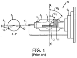
- Fig. 1 shows a cross section of a prior art gas-discharge lamp 10, with a partial coating 11, 12 comprising a circumferentially arranged stripe 11 and a pair of longitudinally arranged stripes 12, 13.
- the lamp 10 shown corresponds to a D4R lamp, with a ballast 6 or base 6, for use in an automotive headlight assembly.
- the width of the circumferential stripe 11 is defmed in the appropriate regulation, in this case ECE R99, by the angles ⁇ 1 , ⁇ 2 subtended at the lamp centre between a radius r and points on the outer edges of the circumferential stripe 11.
- ECE R99 requires that the smaller angle ⁇ 1 be 45° ⁇ 5°, and that the larger angle ⁇ 2 be at least 70°.
- a circumferential stripe 11 can therefore have a width of about 8.3 mm, and usually covers a substantial part of the underlying pinch region.
- a pair of longitudinal stripes 12, 13 is arranged one of each side of the lamp 10. This is illustrated in the cross-section A-A' shown on the left of the diagram. According to the regulation ECE R99, these longitudinal stripes 12, 13 are arranged asymmetrically on the lamp outer vessel 5 such that one stripe 13 is lower than the other stripe 12.
- the 'higher' stripe 12 is positioned to lie just below the horizontal plane P, while the upper edge of the lower stripe 13 is positioned at most 15° below the horizontal plane P.
- Fig. 2 shows a gas-discharge lamp 1 according to a first embodiment of the invention.
- the construction of the lamp 1 is essentially the same as in the above Fig. 1 , in order to comply with regulations regarding lamp size, ballast, etc.
- the relative sizes of the inner and outer vessels 4, 5 will depend on whether the lamp is realised as a 25 W lamp or a 35 W lamp.
- a rectangular vertical stripe S v is arranged about the circumference of the outer vessel 5 of the lamp 1, such that the short ends of the vertical stripe Sv do not meet on the underside of the lamp 1.
- the width wv of the circumferential stripe S v is defined by the angles ⁇ v1 , ⁇ v2 subtended between the radial cross-section through the lamp centre and points on the outer edges 14, 15 of the circumferential stripe S v .
- the smaller angle ⁇ v1 to the inner edge 15 closer to the burner 4 is about 50°
- the larger angle ⁇ v2 to the outer edge 14 closer to the base 6 is only about 55°. Therefore, the circumferential stripe S v has a width w v of about 3.5 mm, so that it only covers a small section of the underlying pinch region.
- the diagram also shows two horizontal stripes S H arranged symmetrically on the outer vessel 5.
- the horizontal stripes S H are arranged symmetrically on either side of the lamp 1, are positioned lower down, and are narrower than the prior art stripes 12, 13. This is illustrated in the cross-section A-A' shown on the left of the diagram.
- the longitudinal stripes S H are arranged symmetrically on the lamp outer vessel 5 such that an angle ⁇ H1 , ⁇ H2 subtended at the lamp centre between the horizontal plane P and a point on an upper edge 16, 17 of a longitudinal stripe S H comprises 15°.
- the angular region ⁇ H between the upper edges 16, 17 of the horizontal stripes S H and below the horizontal plane P comprises only 150°.
- the light output of the lamp 1 is increased, since less light is blocked by the lower and narrower longitudinal stripes S H , and more 'useful' arc images can be collected by a surrounding reflector and used to form a brighter front beam, as will be shown below.
- Fig. 3 shows a further embodiment of a lamp 1 according to the invention.
- a vertical stripe S v ' and a horizontal stripe S H ' are arranged as shown on the outer surface of the outer vessel 5.
- the vertical stripe S v ' extends all the way around the outer vessel 5, and the horizontal stripe S H ' comprises a single stripe S H '.
- the position and width of the vertical stripe S v ' can be the same as in Fig 2 above.
- the defining angle ⁇ H1 , ⁇ H2 of the horizontal stripe S H ' can be smaller, for example 10°, as shown in the cross-section A-A' on the left of the diagram.
- the angular region ⁇ H between the upper edges 16, 17 of the horizontal stripes S H comprises 160°.
- the stripes were required to provide an asymmetric light source, and the prior art reflectors were largely symmetrical.
- the lamp 1 according to the invention makes use of the fact that the reflectors available at present can be favourably designed to form light - even light originating from a symmetrical light source - into an asymmetric front beam. Since the reflector can achieve the required asymmetry largely on its own, the width and placement of the stripes can be favourably adjusted as described above to optimise the light output and to prolong the lamp lifetime.
- Fig. 4 shows a lighting assembly 9 with a lamp 1 according to the invention and a reflector 8.
- the circumferential stripe S v ' is narrow, so that light L s , which is in any case superfluous, can pass through the outer vessel 5 into the base region of the lamp 1.
- This light can, for example, be absorbed in the rear of the reflector 8 or can pass through an opening 83 in the rear of the reflector 8. 'Wasting' the superfluous light L s in this way does not detract from the beam quality. Instead, the lamp 1 is protected from overheating by the narrow width of the vertical stripe S v '.
- Fig. 5 illustrates the beneficial effect of the inventive arrangement of horizontal stripes S H on a lamp 1 in a reflector 8 for an automotive headlamp arrangement.
- a cross-section through the lamp 1 and reflector 8 is shown, and regions 80A, 80B, 81A, 81B are indicated on the inside surface of the reflector 8.
- Images 20A, 20B, 21A, 21B of the discharge arc 2 originating from light L 20A , L 20B , L 21A , L 21B collected at these regions 80A, 80B, 81A, 81B, are projected onto the beam profile 3 according to the relevant regulation, for example R98, as shown in the left-hand side of the diagram.
- Images 20A, 20B show the region close to the cut-off 31 and in the shoulder 32 that can be illuminated with a prior art lamp having higher horizontal stripes. Because these arc images 20A, 20B are collected relatively high up in the reflector 8, near to or above the horizontal plane P, they are not tilted to any significant extent, and lie more or less along the cut-off line of the beam profile 3.
- the additional images 21A, 21B (solid lines) that are projected into the beam profile 3 ensure a better illumination by the front beam owing to the greater light flux and the longer reach of the front beam.
- These additional images 21A, 21B are collected on account of the inventive lower arrangement of longitudinal stripes S H on the outer vessel 5. Because these images 21A, 21B are collected lower down in the reflector 8, they are tilted noticeably compared to the other arc images 20A, 20B, and make a favourable contribution to the overall brightness of the beam profile.
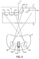
- Fig. 6 shows a view of a reflector 8 used in the lighting assembly according to the invention.
- a lamp 1 with a stripe arrangement S v , S v ', S H , S H ' according to the invention is mounted horizontally in the reflector. Images of the discharge arc 2, collected in the interior of the reflector 8, are deflected outward to give a beam profile 3 with a desired cut-off line 31 and a shoulder 32 relative to axes H, V.
- the diagram shows the regions 81A, 81B for collecting additional light L 21A , L 21B allowed by the lower placement of horizontal stripes S H , S H '. This additional light is deflected onto the beam profile as the arc images 21A, 21B.
- the positions and orientations of these additional arc images 21A, 21B in the diagram is exemplary.
- the position of the horizontal stripe(s) S H , S H ' and the actual realisation of the reflector regions 81A, 81B will influence the orientation and positioning of the arc images 21A, 21B.
- a lower placement of the horizontal stripe(s) S H , S H ' will result in a more tilted arc image 21A, 21B.
- Using this reflector 8 with the inventive lamp 1 allows a better illumination of the region in front of the vehicle between 25 m and 60 m owing to the improved reach of the beam and to the better illumination in the cut-off 31 and shoulder 32 regions of the beam profile 3.
- Figs. 7 - 9 show experimental results obtained for 35 W and 25 W D4R lamp batches A35, A25 according to the invention, for D4R 35 W and 25 W lamp batches B35, B25 with a prior art pinstripe arrangements, and for D4R 35 W and 25 W lamp batches C35, C25 with no pinstripes.
- Fig. 7 shows a bar chart of initial lumen output in percent (%) for different batches of automotive gas-discharge lamps measured 15 hours after burning in.
- Batch B35 comprised prior art 35 W lamps with pinstripes arranged according to the R99 regulation, while batch B25 comprised prior art 25 W lamps with such pinstripes.
- Batches C35, C25 comprised 35 W and 25 W D4R lamps respectively, without any stripes.
- an automotive lamp 25 W or 35 W lamp must deliver 3200 ⁇ 450 lumens at 15 hours after burning in.
- the light output that can be achieved initially is given as 100%.
- Batch A35 comprised 35 W lamps and batch A25 comprised 25 W lamps, in each case with horizontal stripes arranged according to the invention, i.e.
- the lamp according to the invention while having stripes to assist in obtaining a desired beam shape, can still provide an initial lumen output favourably close to that of a lamp without any stripes.
- Fig. 8 shows graphs of lumen maintenance measured for the lamp type batches A25, B25, C25 of Fig. 1 after 1500 hours of burning.
- An initial value of 100% corresponds to the lumen output of each lamp batch type after burning in.
- Lamp type batch B25 showed relatively poor lumen maintenance, dropping to only about 89% of its initial value after 1500 hours.
- Batch A25 showed quite favourable lumen maintenance, dropping only to about 92%.
- the burner is small, but the outer vessel is of the same size as for a 35 W lamp.
- the clearance between burner and outer vessel is greater, and the coefficient of thermal conductivity is lower.
- the burner is therefore to some extent thermally insulated from the outer vessel, so that heat generated because of the stripe regions does not affect the temperature in the burner to the same extent as in a prior art 35 W lamps.
- This explains the very favourable lumen maintenance of the 25 W lamps according to the invention. Measurements taken for the lamp batches A35, B35, C35 showed a drop in lumen maintenance to 82%, 72% and 87% respectively after 2000 hours of burning, so that the 35 W lamp A35 with the inventive pinstripe arrangement exhibited a favourable lumen maintenance compared to a prior art lamp B35 with pinstripes.
- Fig. 9 shows graphs of lamp voltage measured for batches A25, B25, C25 of Fig. 7 and Fig. 8 after 1500 hours of burning.
- An initial value of 100% corresponds to the lamp voltage of each lamp batch type after burning in.
- Lamp batch B25 showed a marked increase in lamp voltage after 1500 hours, rising to about 114%.
- Lamp batch A25 showed a very favourably low increase in lamp voltage, which rose to only about 109%. Positive effects of the low increase in lamp voltage are a reduced tendency to flicker and a prolonged lamp lifetime.
- the temperature in the 25 W lamp according to the invention can be maintained at a favourably low level, which explains the slower increase in lamp voltage even compared to a 35 W lamp with inventive stripe arrangement.
- Measurements taken for the lamp batches A35, B35, C35 showed an increase in lamp voltage of 127%, 131% and 135% respectively after 2000 hours of burning, so that the 35 W lamp with the inventive pinstripe arrangement exhibited the lowest percent increase in lamp voltage over lamp lifetime.
Landscapes
- Non-Portable Lighting Devices Or Systems Thereof (AREA)
- Vessels And Coating Films For Discharge Lamps (AREA)
Priority Applications (1)
| Application Number | Priority Date | Filing Date | Title |
|---|---|---|---|
| EP11727779.8A EP2577713B1 (en) | 2010-05-26 | 2011-05-18 | Gas discharge lamp with a partially coated vessel for an automotive headlamp |
Applications Claiming Priority (3)
| Application Number | Priority Date | Filing Date | Title |
|---|---|---|---|
| EP10163953 | 2010-05-26 | ||
| EP11727779.8A EP2577713B1 (en) | 2010-05-26 | 2011-05-18 | Gas discharge lamp with a partially coated vessel for an automotive headlamp |
| PCT/IB2011/052172 WO2011148295A2 (en) | 2010-05-26 | 2011-05-18 | Gas-discharge lamp |
Publications (2)
| Publication Number | Publication Date |
|---|---|
| EP2577713A2 EP2577713A2 (en) | 2013-04-10 |
| EP2577713B1 true EP2577713B1 (en) | 2013-12-04 |
Family
ID=44359817
Family Applications (1)
| Application Number | Title | Priority Date | Filing Date |
|---|---|---|---|
| EP11727779.8A Not-in-force EP2577713B1 (en) | 2010-05-26 | 2011-05-18 | Gas discharge lamp with a partially coated vessel for an automotive headlamp |
Country Status (5)
| Country | Link |
|---|---|
| US (1) | US9058970B2 (enExample) |
| EP (1) | EP2577713B1 (enExample) |
| JP (1) | JP5872549B2 (enExample) |
| CN (1) | CN102906853B (enExample) |
| WO (1) | WO2011148295A2 (enExample) |
Families Citing this family (4)
| Publication number | Priority date | Publication date | Assignee | Title |
|---|---|---|---|---|
| US9711342B2 (en) * | 2010-05-26 | 2017-07-18 | Koninklijke Philips N.V. | Gas-discharge lamp |
| JP2016181397A (ja) * | 2015-03-24 | 2016-10-13 | 東芝ライテック株式会社 | 放電ランプ |
| KR102567206B1 (ko) | 2015-06-03 | 2023-08-14 | 쓰리엠 이노베이티브 프로퍼티즈 컴파니 | 아크릴-기반 가요성 조립체 층 |
| KR102024481B1 (ko) | 2015-06-03 | 2019-09-23 | 쓰리엠 이노베이티브 프로퍼티즈 컴파니 | 가요성 디스플레이용 조립체 층 |
Family Cites Families (14)
| Publication number | Priority date | Publication date | Assignee | Title |
|---|---|---|---|---|
| DE29507422U1 (de) * | 1994-05-10 | 1995-06-29 | Philips Electronics N.V., Eindhoven | Gesockelte Hochdruckentladungslampe |
| JP3740626B2 (ja) * | 1998-02-13 | 2006-02-01 | スタンレー電気株式会社 | 車両用放電管 |
| DE19844839B4 (de) * | 1998-09-30 | 2010-07-22 | Automotive Lighting Reutlingen Gmbh | Scheinwerfer für Fahrzeuge |
| JP2000149640A (ja) * | 1998-11-17 | 2000-05-30 | Koito Mfg Co Ltd | 車両用前照灯 |
| JP4489206B2 (ja) | 1999-04-28 | 2010-06-23 | パナソニック フォト・ライティング 株式会社 | 閃光放電管 |
| JP3868674B2 (ja) | 1999-08-09 | 2007-01-17 | 株式会社小糸製作所 | 光源バルブの製造方法 |
| US6583564B1 (en) * | 1999-11-17 | 2003-06-24 | Matsushita Electric Industrial Co., Ltd. | Discharge lamp with light-intercepting film bands |
| JP2001210112A (ja) * | 1999-11-17 | 2001-08-03 | Matsushita Electric Ind Co Ltd | 放電ランプ |
| JP2002109915A (ja) * | 2000-09-27 | 2002-04-12 | Koito Mfg Co Ltd | 車両用前照灯 |
| JP3964149B2 (ja) * | 2001-04-10 | 2007-08-22 | 株式会社小糸製作所 | 車両用前照灯 |
| EP1554745A2 (en) * | 2002-07-23 | 2005-07-20 | Philips Intellectual Property & Standards GmbH | Lamp |
| AU2003302553A1 (en) | 2002-12-02 | 2004-06-23 | Koninklijke Philips Electronics N.V. | Vehicle headlamp |
| JP4440019B2 (ja) | 2004-07-09 | 2010-03-24 | 株式会社小糸製作所 | 自動車前照灯用放電バルブ |
| US9711342B2 (en) * | 2010-05-26 | 2017-07-18 | Koninklijke Philips N.V. | Gas-discharge lamp |
-
2011
- 2011-05-18 WO PCT/IB2011/052172 patent/WO2011148295A2/en not_active Ceased
- 2011-05-18 US US13/699,229 patent/US9058970B2/en not_active Expired - Fee Related
- 2011-05-18 CN CN201180025922.2A patent/CN102906853B/zh not_active Expired - Fee Related
- 2011-05-18 JP JP2013511766A patent/JP5872549B2/ja not_active Expired - Fee Related
- 2011-05-18 EP EP11727779.8A patent/EP2577713B1/en not_active Not-in-force
Also Published As
| Publication number | Publication date |
|---|---|
| CN102906853A (zh) | 2013-01-30 |
| EP2577713A2 (en) | 2013-04-10 |
| CN102906853B (zh) | 2015-11-25 |
| JP2013531865A (ja) | 2013-08-08 |
| WO2011148295A3 (en) | 2012-03-01 |
| US20130070468A1 (en) | 2013-03-21 |
| US9058970B2 (en) | 2015-06-16 |
| JP5872549B2 (ja) | 2016-03-01 |
| WO2011148295A2 (en) | 2011-12-01 |
Similar Documents
| Publication | Publication Date | Title |
|---|---|---|
| US5646471A (en) | Capped high-pressure discharge lamp | |
| US3688149A (en) | Vehicle headlamp having a dual-segment reflector | |
| KR20050084046A (ko) | 자동차 전조등 | |
| EP2577713B1 (en) | Gas discharge lamp with a partially coated vessel for an automotive headlamp | |
| JPH0197301A (ja) | 自動車用のすれ違いビームヘッドランプ | |
| US3818210A (en) | Vehicular road-lighting system having a headlamp with a dual-segment reflector | |
| EP2143130A2 (en) | Mercury-free high intensity gas-discharge lamp | |
| EP2577714B1 (en) | Partially coated gas discharge lamp | |
| US4303965A (en) | Single-mode vehicular headlamp system | |
| US9406497B2 (en) | High intensity discharge lamp | |
| JP3562687B2 (ja) | プロジェクタ型ランプ | |
| US20130038207A1 (en) | Mercury-free high intensity gas-discharge lamp | |
| JP2008511111A (ja) | 減光機能を特色とする車両ヘッドライトに対するランプ | |
| JPH10261302A (ja) | プロジェクタ型ランプ | |
| NL7908757A (nl) | Elektrische stralingslamp, in het bijzonder een sealed-beam voertuiglamp. | |
| JP5389915B2 (ja) | 自動車ランプ | |
| US20120126694A1 (en) | Mercury-free high intensity gas-discharge lamp | |
| JPH029442Y2 (enExample) | ||
| JPH029443Y2 (enExample) | ||
| WO2004099667A2 (en) | Lamp for a motor vehicle headlight | |
| JPS6293851A (ja) | 車両用前照灯 | |
| Reif | Lighting technology |
Legal Events
| Date | Code | Title | Description |
|---|---|---|---|
| PUAI | Public reference made under article 153(3) epc to a published international application that has entered the european phase |
Free format text: ORIGINAL CODE: 0009012 |
|
| 17P | Request for examination filed |
Effective date: 20130102 |
|
| AK | Designated contracting states |
Kind code of ref document: A2 Designated state(s): AL AT BE BG CH CY CZ DE DK EE ES FI FR GB GR HR HU IE IS IT LI LT LU LV MC MK MT NL NO PL PT RO RS SE SI SK SM TR |
|
| GRAP | Despatch of communication of intention to grant a patent |
Free format text: ORIGINAL CODE: EPIDOSNIGR1 |
|
| DAX | Request for extension of the european patent (deleted) | ||
| INTG | Intention to grant announced |
Effective date: 20130725 |
|
| RAP1 | Party data changed (applicant data changed or rights of an application transferred) |
Owner name: KONINKLIJKE PHILIPS N.V. Owner name: PHILIPS INTELLECTUAL PROPERTY & STANDARDS GMBH |
|
| GRAS | Grant fee paid |
Free format text: ORIGINAL CODE: EPIDOSNIGR3 |
|
| GRAA | (expected) grant |
Free format text: ORIGINAL CODE: 0009210 |
|
| AK | Designated contracting states |
Kind code of ref document: B1 Designated state(s): AL AT BE BG CH CY CZ DE DK EE ES FI FR GB GR HR HU IE IS IT LI LT LU LV MC MK MT NL NO PL PT RO RS SE SI SK SM TR |
|
| REG | Reference to a national code |
Ref country code: GB Ref legal event code: FG4D |
|
| REG | Reference to a national code |
Ref country code: CH Ref legal event code: EP |
|
| REG | Reference to a national code |
Ref country code: AT Ref legal event code: REF Ref document number: 643825 Country of ref document: AT Kind code of ref document: T Effective date: 20140115 Ref country code: IE Ref legal event code: FG4D |
|
| REG | Reference to a national code |
Ref country code: DE Ref legal event code: R096 Ref document number: 602011004054 Country of ref document: DE Effective date: 20140130 |
|
| REG | Reference to a national code |
Ref country code: GB Ref legal event code: 746 Effective date: 20140304 Ref country code: NL Ref legal event code: VDEP Effective date: 20131204 |
|
| REG | Reference to a national code |
Ref country code: AT Ref legal event code: MK05 Ref document number: 643825 Country of ref document: AT Kind code of ref document: T Effective date: 20131204 |
|
| PG25 | Lapsed in a contracting state [announced via postgrant information from national office to epo] |
Ref country code: NO Free format text: LAPSE BECAUSE OF FAILURE TO SUBMIT A TRANSLATION OF THE DESCRIPTION OR TO PAY THE FEE WITHIN THE PRESCRIBED TIME-LIMIT Effective date: 20140304 Ref country code: FI Free format text: LAPSE BECAUSE OF FAILURE TO SUBMIT A TRANSLATION OF THE DESCRIPTION OR TO PAY THE FEE WITHIN THE PRESCRIBED TIME-LIMIT Effective date: 20131204 Ref country code: HR Free format text: LAPSE BECAUSE OF FAILURE TO SUBMIT A TRANSLATION OF THE DESCRIPTION OR TO PAY THE FEE WITHIN THE PRESCRIBED TIME-LIMIT Effective date: 20131204 Ref country code: NL Free format text: LAPSE BECAUSE OF FAILURE TO SUBMIT A TRANSLATION OF THE DESCRIPTION OR TO PAY THE FEE WITHIN THE PRESCRIBED TIME-LIMIT Effective date: 20131204 Ref country code: LT Free format text: LAPSE BECAUSE OF FAILURE TO SUBMIT A TRANSLATION OF THE DESCRIPTION OR TO PAY THE FEE WITHIN THE PRESCRIBED TIME-LIMIT Effective date: 20131204 Ref country code: SE Free format text: LAPSE BECAUSE OF FAILURE TO SUBMIT A TRANSLATION OF THE DESCRIPTION OR TO PAY THE FEE WITHIN THE PRESCRIBED TIME-LIMIT Effective date: 20131204 |
|
| REG | Reference to a national code |
Ref country code: DE Ref legal event code: R081 Ref document number: 602011004054 Country of ref document: DE Owner name: PHILIPS GMBH, DE Free format text: FORMER OWNER: PHILIPS INTELLECTUAL PROPERTY & STANDARDS GMBH, 20099 HAMBURG, DE Effective date: 20140327 Ref country code: DE Ref legal event code: R081 Ref document number: 602011004054 Country of ref document: DE Owner name: PHILIPS DEUTSCHLAND GMBH, DE Free format text: FORMER OWNER: PHILIPS INTELLECTUAL PROPERTY & STANDARDS GMBH, 20099 HAMBURG, DE Effective date: 20140327 |
|
| REG | Reference to a national code |
Ref country code: LT Ref legal event code: MG4D |
|
| PG25 | Lapsed in a contracting state [announced via postgrant information from national office to epo] |
Ref country code: RS Free format text: LAPSE BECAUSE OF FAILURE TO SUBMIT A TRANSLATION OF THE DESCRIPTION OR TO PAY THE FEE WITHIN THE PRESCRIBED TIME-LIMIT Effective date: 20131204 Ref country code: LV Free format text: LAPSE BECAUSE OF FAILURE TO SUBMIT A TRANSLATION OF THE DESCRIPTION OR TO PAY THE FEE WITHIN THE PRESCRIBED TIME-LIMIT Effective date: 20131204 Ref country code: CY Free format text: LAPSE BECAUSE OF FAILURE TO SUBMIT A TRANSLATION OF THE DESCRIPTION OR TO PAY THE FEE WITHIN THE PRESCRIBED TIME-LIMIT Effective date: 20131204 Ref country code: AT Free format text: LAPSE BECAUSE OF FAILURE TO SUBMIT A TRANSLATION OF THE DESCRIPTION OR TO PAY THE FEE WITHIN THE PRESCRIBED TIME-LIMIT Effective date: 20131204 |
|
| PG25 | Lapsed in a contracting state [announced via postgrant information from national office to epo] |
Ref country code: IS Free format text: LAPSE BECAUSE OF FAILURE TO SUBMIT A TRANSLATION OF THE DESCRIPTION OR TO PAY THE FEE WITHIN THE PRESCRIBED TIME-LIMIT Effective date: 20140404 Ref country code: BE Free format text: LAPSE BECAUSE OF FAILURE TO SUBMIT A TRANSLATION OF THE DESCRIPTION OR TO PAY THE FEE WITHIN THE PRESCRIBED TIME-LIMIT Effective date: 20131204 Ref country code: EE Free format text: LAPSE BECAUSE OF FAILURE TO SUBMIT A TRANSLATION OF THE DESCRIPTION OR TO PAY THE FEE WITHIN THE PRESCRIBED TIME-LIMIT Effective date: 20131204 |
|
| PG25 | Lapsed in a contracting state [announced via postgrant information from national office to epo] |
Ref country code: CZ Free format text: LAPSE BECAUSE OF FAILURE TO SUBMIT A TRANSLATION OF THE DESCRIPTION OR TO PAY THE FEE WITHIN THE PRESCRIBED TIME-LIMIT Effective date: 20131204 Ref country code: SK Free format text: LAPSE BECAUSE OF FAILURE TO SUBMIT A TRANSLATION OF THE DESCRIPTION OR TO PAY THE FEE WITHIN THE PRESCRIBED TIME-LIMIT Effective date: 20131204 Ref country code: PT Free format text: LAPSE BECAUSE OF FAILURE TO SUBMIT A TRANSLATION OF THE DESCRIPTION OR TO PAY THE FEE WITHIN THE PRESCRIBED TIME-LIMIT Effective date: 20140404 Ref country code: RO Free format text: LAPSE BECAUSE OF FAILURE TO SUBMIT A TRANSLATION OF THE DESCRIPTION OR TO PAY THE FEE WITHIN THE PRESCRIBED TIME-LIMIT Effective date: 20131204 Ref country code: PL Free format text: LAPSE BECAUSE OF FAILURE TO SUBMIT A TRANSLATION OF THE DESCRIPTION OR TO PAY THE FEE WITHIN THE PRESCRIBED TIME-LIMIT Effective date: 20131204 Ref country code: ES Free format text: LAPSE BECAUSE OF FAILURE TO SUBMIT A TRANSLATION OF THE DESCRIPTION OR TO PAY THE FEE WITHIN THE PRESCRIBED TIME-LIMIT Effective date: 20131204 |
|
| REG | Reference to a national code |
Ref country code: DE Ref legal event code: R097 Ref document number: 602011004054 Country of ref document: DE |
|
| PLBE | No opposition filed within time limit |
Free format text: ORIGINAL CODE: 0009261 |
|
| STAA | Information on the status of an ep patent application or granted ep patent |
Free format text: STATUS: NO OPPOSITION FILED WITHIN TIME LIMIT |
|
| PG25 | Lapsed in a contracting state [announced via postgrant information from national office to epo] |
Ref country code: DK Free format text: LAPSE BECAUSE OF FAILURE TO SUBMIT A TRANSLATION OF THE DESCRIPTION OR TO PAY THE FEE WITHIN THE PRESCRIBED TIME-LIMIT Effective date: 20131204 |
|
| 26N | No opposition filed |
Effective date: 20140905 |
|
| REG | Reference to a national code |
Ref country code: DE Ref legal event code: R097 Ref document number: 602011004054 Country of ref document: DE Effective date: 20140905 |
|
| PG25 | Lapsed in a contracting state [announced via postgrant information from national office to epo] |
Ref country code: LU Free format text: LAPSE BECAUSE OF FAILURE TO SUBMIT A TRANSLATION OF THE DESCRIPTION OR TO PAY THE FEE WITHIN THE PRESCRIBED TIME-LIMIT Effective date: 20140518 |
|
| REG | Reference to a national code |
Ref country code: CH Ref legal event code: PL |
|
| PG25 | Lapsed in a contracting state [announced via postgrant information from national office to epo] |
Ref country code: MC Free format text: LAPSE BECAUSE OF FAILURE TO SUBMIT A TRANSLATION OF THE DESCRIPTION OR TO PAY THE FEE WITHIN THE PRESCRIBED TIME-LIMIT Effective date: 20131204 Ref country code: LI Free format text: LAPSE BECAUSE OF NON-PAYMENT OF DUE FEES Effective date: 20140531 Ref country code: CH Free format text: LAPSE BECAUSE OF NON-PAYMENT OF DUE FEES Effective date: 20140531 |
|
| REG | Reference to a national code |
Ref country code: IE Ref legal event code: MM4A |
|
| PG25 | Lapsed in a contracting state [announced via postgrant information from national office to epo] |
Ref country code: SI Free format text: LAPSE BECAUSE OF FAILURE TO SUBMIT A TRANSLATION OF THE DESCRIPTION OR TO PAY THE FEE WITHIN THE PRESCRIBED TIME-LIMIT Effective date: 20131204 |
|
| PG25 | Lapsed in a contracting state [announced via postgrant information from national office to epo] |
Ref country code: IT Free format text: LAPSE BECAUSE OF FAILURE TO SUBMIT A TRANSLATION OF THE DESCRIPTION OR TO PAY THE FEE WITHIN THE PRESCRIBED TIME-LIMIT Effective date: 20131204 Ref country code: IE Free format text: LAPSE BECAUSE OF NON-PAYMENT OF DUE FEES Effective date: 20140518 |
|
| REG | Reference to a national code |
Ref country code: DE Ref legal event code: R082 Ref document number: 602011004054 Country of ref document: DE Representative=s name: MEISSNER, BOLTE & PARTNER GBR, DE Ref country code: DE Ref legal event code: R081 Ref document number: 602011004054 Country of ref document: DE Owner name: PHILIPS GMBH, DE Free format text: FORMER OWNER: PHILIPS DEUTSCHLAND GMBH, 20099 HAMBURG, DE Ref country code: DE Ref legal event code: R082 Ref document number: 602011004054 Country of ref document: DE Representative=s name: MEISSNER BOLTE PATENTANWAELTE RECHTSANWAELTE P, DE |
|
| PG25 | Lapsed in a contracting state [announced via postgrant information from national office to epo] |
Ref country code: MT Free format text: LAPSE BECAUSE OF FAILURE TO SUBMIT A TRANSLATION OF THE DESCRIPTION OR TO PAY THE FEE WITHIN THE PRESCRIBED TIME-LIMIT Effective date: 20131204 |
|
| PG25 | Lapsed in a contracting state [announced via postgrant information from national office to epo] |
Ref country code: SM Free format text: LAPSE BECAUSE OF FAILURE TO SUBMIT A TRANSLATION OF THE DESCRIPTION OR TO PAY THE FEE WITHIN THE PRESCRIBED TIME-LIMIT Effective date: 20131204 |
|
| REG | Reference to a national code |
Ref country code: FR Ref legal event code: PLFP Year of fee payment: 6 |
|
| PG25 | Lapsed in a contracting state [announced via postgrant information from national office to epo] |
Ref country code: GR Free format text: LAPSE BECAUSE OF FAILURE TO SUBMIT A TRANSLATION OF THE DESCRIPTION OR TO PAY THE FEE WITHIN THE PRESCRIBED TIME-LIMIT Effective date: 20140305 Ref country code: BG Free format text: LAPSE BECAUSE OF FAILURE TO SUBMIT A TRANSLATION OF THE DESCRIPTION OR TO PAY THE FEE WITHIN THE PRESCRIBED TIME-LIMIT Effective date: 20131204 |
|
| PG25 | Lapsed in a contracting state [announced via postgrant information from national office to epo] |
Ref country code: HU Free format text: LAPSE BECAUSE OF FAILURE TO SUBMIT A TRANSLATION OF THE DESCRIPTION OR TO PAY THE FEE WITHIN THE PRESCRIBED TIME-LIMIT; INVALID AB INITIO Effective date: 20110518 Ref country code: TR Free format text: LAPSE BECAUSE OF FAILURE TO SUBMIT A TRANSLATION OF THE DESCRIPTION OR TO PAY THE FEE WITHIN THE PRESCRIBED TIME-LIMIT Effective date: 20131204 |
|
| REG | Reference to a national code |
Ref country code: FR Ref legal event code: PLFP Year of fee payment: 7 |
|
| REG | Reference to a national code |
Ref country code: FR Ref legal event code: PLFP Year of fee payment: 8 |
|
| PG25 | Lapsed in a contracting state [announced via postgrant information from national office to epo] |
Ref country code: MK Free format text: LAPSE BECAUSE OF FAILURE TO SUBMIT A TRANSLATION OF THE DESCRIPTION OR TO PAY THE FEE WITHIN THE PRESCRIBED TIME-LIMIT Effective date: 20131204 |
|
| REG | Reference to a national code |
Ref country code: GB Ref legal event code: 732E Free format text: REGISTERED BETWEEN 20180920 AND 20180926 |
|
| PG25 | Lapsed in a contracting state [announced via postgrant information from national office to epo] |
Ref country code: AL Free format text: LAPSE BECAUSE OF FAILURE TO SUBMIT A TRANSLATION OF THE DESCRIPTION OR TO PAY THE FEE WITHIN THE PRESCRIBED TIME-LIMIT Effective date: 20131204 |
|
| REG | Reference to a national code |
Ref country code: DE Ref legal event code: R082 Ref document number: 602011004054 Country of ref document: DE Ref country code: DE Ref legal event code: R081 Ref document number: 602011004054 Country of ref document: DE Owner name: LUMILEDS HOLDING B.V., NL Free format text: FORMER OWNER: PHILIPS GMBH, 20099 HAMBURG, DE |
|
| PGFP | Annual fee paid to national office [announced via postgrant information from national office to epo] |
Ref country code: DE Payment date: 20200529 Year of fee payment: 10 Ref country code: FR Payment date: 20200527 Year of fee payment: 10 |
|
| PGFP | Annual fee paid to national office [announced via postgrant information from national office to epo] |
Ref country code: GB Payment date: 20200528 Year of fee payment: 10 |
|
| REG | Reference to a national code |
Ref country code: DE Ref legal event code: R119 Ref document number: 602011004054 Country of ref document: DE |
|
| GBPC | Gb: european patent ceased through non-payment of renewal fee |
Effective date: 20210518 |
|
| PG25 | Lapsed in a contracting state [announced via postgrant information from national office to epo] |
Ref country code: GB Free format text: LAPSE BECAUSE OF NON-PAYMENT OF DUE FEES Effective date: 20210518 Ref country code: DE Free format text: LAPSE BECAUSE OF NON-PAYMENT OF DUE FEES Effective date: 20211201 |
|
| PG25 | Lapsed in a contracting state [announced via postgrant information from national office to epo] |
Ref country code: FR Free format text: LAPSE BECAUSE OF NON-PAYMENT OF DUE FEES Effective date: 20210531 |