EP2576947B1 - Charnière de meuble - Google Patents
Charnière de meuble Download PDFInfo
- Publication number
- EP2576947B1 EP2576947B1 EP11721293.6A EP11721293A EP2576947B1 EP 2576947 B1 EP2576947 B1 EP 2576947B1 EP 11721293 A EP11721293 A EP 11721293A EP 2576947 B1 EP2576947 B1 EP 2576947B1
- Authority
- EP
- European Patent Office
- Prior art keywords
- spacer element
- furniture hinge
- lever
- guide lever
- hinge according
- Prior art date
- Legal status (The legal status is an assumption and is not a legal conclusion. Google has not performed a legal analysis and makes no representation as to the accuracy of the status listed.)
- Active
Links
- 125000006850 spacer group Chemical group 0.000 claims description 65
- 239000002184 metal Substances 0.000 claims description 2
- 230000000630 rising effect Effects 0.000 claims description 2
- 238000010276 construction Methods 0.000 description 1
- 230000001419 dependent effect Effects 0.000 description 1
- 238000009434 installation Methods 0.000 description 1
- 238000004519 manufacturing process Methods 0.000 description 1
Images


Classifications
-
- E—FIXED CONSTRUCTIONS
- E05—LOCKS; KEYS; WINDOW OR DOOR FITTINGS; SAFES
- E05D—HINGES OR SUSPENSION DEVICES FOR DOORS, WINDOWS OR WINGS
- E05D11/00—Additional features or accessories of hinges
- E05D11/06—Devices for limiting the opening movement of hinges
-
- E—FIXED CONSTRUCTIONS
- E05—LOCKS; KEYS; WINDOW OR DOOR FITTINGS; SAFES
- E05D—HINGES OR SUSPENSION DEVICES FOR DOORS, WINDOWS OR WINGS
- E05D3/00—Hinges with pins
- E05D3/06—Hinges with pins with two or more pins
- E05D3/14—Hinges with pins with two or more pins with four parallel pins and two arms
- E05D3/142—Hinges with pins with two or more pins with four parallel pins and two arms with at least one of the hinge parts having a cup-shaped fixing part, e.g. for attachment to cabinets or furniture
-
- E—FIXED CONSTRUCTIONS
- E05—LOCKS; KEYS; WINDOW OR DOOR FITTINGS; SAFES
- E05Y—INDEXING SCHEME RELATING TO HINGES OR OTHER SUSPENSION DEVICES FOR DOORS, WINDOWS OR WINGS AND DEVICES FOR MOVING WINGS INTO OPEN OR CLOSED POSITION, CHECKS FOR WINGS AND WING FITTINGS NOT OTHERWISE PROVIDED FOR, CONCERNED WITH THE FUNCTIONING OF THE WING
- E05Y2900/00—Application of doors, windows, wings or fittings thereof
- E05Y2900/10—Application of doors, windows, wings or fittings thereof for buildings or parts thereof
- E05Y2900/13—Application of doors, windows, wings or fittings thereof for buildings or parts thereof characterised by the type of wing
- E05Y2900/132—Doors
Definitions
- the present invention relates to a furniture hinge according to the preamble of claim 1.
- Furniture hinges of the present type are known per se and are used without limitation of the opening angle by spacer elements when a disability-free opening a furniture door in a manufacturer's predetermined angular range is readily possible.
- An insert with inserted spacer element comes into consideration when due to the installation situation the opening of a furniture door in a certain angular range is not possible or not desirable and therefore an additional mechanical stop, for example in the hinge cup, to limit the manufacturer side predetermined opening angle range.
- the known furniture hinges with disassembled spacer elements meet the appropriate requirements.
- a disadvantage of the known constructions that must be installed in the furniture hinge for adjusting the furniture hinge for a limited opening angle depending on the desired opening angle additional different spacers.
- a furniture hinge with two stop parts is known in which a screw is used, with which the opening angle of the furniture hinge is variably adjustable.
- the screw is screwed into a support lever and presses with its end against a guide lever, so that the opening angle with the depth of engagement is adjustable.
- Object of the present invention is therefore to provide a furniture hinge of the generic type, in which the opening angle is variably adjustable.
- the furniture hinge is equipped with a spacer element, which is designed as the opening angle of the furniture hinge variably adjustable limiter, wherein the spacer element on its side facing the guide lever has several trained as a contact surfaces for guide lever wedge surfaces with different wedge angles or on a side facing away from the guide lever with a Groove, a recess or an opening for receiving a tool is formed, with which the spacer element is adjustable so that one of the wedge surfaces faces the guide lever with a certain wedge angle.
- the spacer element can be designed so that the setting for limiting the opening angle can be limited continuously from the maximum manufacturer-side predetermined opening angle range to the desired opening angle range.
- the arrangement of the spacer element on the support lever on the side facing the guide lever allows a stable position and a design with large stop surfaces.
- the designed as a contact surfaces with the guide lever wedge surfaces formed with different wedge angles spacer element is easy to manufacture and durable.
- the spacer element is fixed to the support lever.
- the support lever in particular has an opening through which the groove of the spacer element is accessible. In this way, the spacer element can be adjusted in the simplest way.
- the side facing away from the guide lever of the spacer element is one of the number of Wedge surfaces corresponding number of latched to the support lever, preferably formed as a locking cam, locking elements forth.
- At least one marking for displaying the set opening angle is provided on the spacer element according to a further embodiment variant.
- a marking for example in the form of visible color dots o. ⁇ . Markings, this can give information about the set angle of the furniture hinge.
- top, bottom, left, right, front, back, etc. refer exclusively to the example representation and position of the furniture hinge and other parts selected in the respective figures. These terms are not intended to be limiting, that is to say, by different working positions or the mirror-symmetrical design or the like, these references may change.
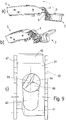
- FIG. 1 is insgesarnt a furniture hinge with a door-side first stop member 2 and a wall-side second stop member 3 is designated by the reference numeral 1, in which the stop members 2 and 3 by a support lever 4 and a guide lever 5 pivotally, preferably four-jointed, are interconnected.
- the first stop member 2 is shown half cut.
- the first stop member 2 is pot-shaped in a known manner and is used for fixing to a (not shown) furniture door.
- the second stop member 3 can be fixed in a conventional manner to a wall of a piece of furniture.
- the opening angle of the furniture hinge 1 can be reduced by a spacer element 6 to a predetermined angle ⁇ , ⁇ , ⁇ .
- the spacer element 6 is arranged between the support lever 4 and the guide lever 5. As shown in Figures 2 and 3, the spacer element 6 is rotatably arranged at the bottom of a directed to the guide lever 5 Vergargung 42 in a circular opening 49 of the support lever 4.
- the spacer element 6 is preferably arranged captively on the support lever 4, preferably the cylindrical piece 62 is riveted or staggered in the sense of a loose riveting.
- the spacer element 6 has on its side facing the guide lever 5 a plurality of contact surfaces to the guide lever 5 formed wedge surfaces 64, 65, 66 with different wedge angles.
- the spacer element 6 in the cylinder piece 62 has a groove 63, recess or opening for receiving a tool, in particular a screwdriver, with which the spacer element 6 can be rotated to a desired opening angle limit of the furniture hinge 1 by aligning select one of the wedge surfaces 64, 65, 66 as contact surfaces with the guide lever 5.
- a tool-free operation option is conceivable.
- the groove 63 is formed in the embodiment variant of the spacer element 6 shown in the figures in a protruding from the guide lever 5 side of the spacer element 6 projecting cylindrical piece 62.
- This cylinder piece 62 protrudes in the installed state in the embossment 42 through the opening 49 of the support lever 4, so that the groove 63 in a simple manner for adjusting the maximum opening angle ⁇ , ⁇ , ⁇ on the furniture hinge 1 is accessible in the open state, since the support lever 4 then is pivoted out of the cup-shaped stop member 2.
- the in the FIGS. 4 to 6 shown embodiment of the spacer element 6 is formed with three wedge surfaces with different wedge angles ⁇ , ⁇ , ⁇ .
- two diametrically arranged locking elements 67 which are preferably designed as both sides formed with the same slope locking cams, out.
- the locking elements engage on the side facing the guide lever 5 side in corresponding clearances 68 on the support lever 4, which are preferably designed as depressions with a wedge-like cross-section, a.
- the clearances 68 are radially disposed around the opening 49 at an angle such that when engaging the locking elements 67, the wedge surfaces 64, 65,66 are aligned so that the guide lever with its side facing the support lever depending on the desired maximum opening angle ⁇ , ⁇ , ⁇ at the opening angle limit on the selected wedge surface 64 or 65 or 66 over a large area (almost flat) strikes. Due to the large-area stop exact compliance with the opening angle limitation over a long life is given.
- the spacer element 6 can be adjusted noticeably from an angular position to a next angular position.
- the two latching elements 67 designed here as latching cams are circumferentially multiply corresponding to the arrangement of the wedge surfaces 64, 65, 66 in order to arrange the cylindrical piece 62 on the side 61 of the spacer element 6 facing away from the guide lever 5.
- the clearances 68 on the side facing the guide lever 5 side of the support lever 4 are of course only twice required.
- FIGS. 6a to 6c show the spacer 6 from different perspectives to represent the differently shaped wedge surfaces 64, 65, 66th
- the support lever 4 consists essentially of the main body 41 with the approximately centrally disposed embossment 42, through which the cylindrical piece 62 of the spacer element 6 protrudes.
- the embossment 42 is formed on its part facing the door-side first stop member 2 part-circular and takes the spacer 6 rotatably circumferentially.
- From the main body 41 of the support lever 4 are lateral bent cheeks 47, 48 are arranged, the respective openings 44, 45 for pivotally mounting the support lever to axes of rotation 7, 8 have.
- a contour of the axis of rotation 7 following tongue 46 is formed at one of the door-side first stop member 2 facing end face of the support lever 4 .
- the base body 41 is formed in a preferred embodiment with position indicator marks 43 arranged around the embossment 42, by which the selected adjustment of the opening angle of the spacer element 6, e.g. by the position of the groove 63, can be seen.
- the spacer element 6 is preferably formed in one piece and is preferably made of a metal.
- FIGS. 8a, b . c to 10a . b, c the furniture hinge 1 is shown in different views with different set spacer 6.
- FIGS. 8a to c a setting of the spacer element 6, wherein the furniture hinge 1 is set to a first relatively small opening angle ⁇ , in which the wedge surface 65 of the spacer element 6 comes with the guide lever 5 when opening the furniture hinge 1 into abutment.
- the spacer element 6 is set to an angle ⁇ , wherein the wedge surface 66 comes when opening the furniture hinge 1 with the guide lever 5 into abutment.
- the limitation of this opening angle can preferably be made up to an opening angle of about 80 °.
- the widest open position of the opening angle is preferably about 107 °.
- other maximum and minimum open positions of the opening angle are also conceivable.
Landscapes
- Engineering & Computer Science (AREA)
- Mechanical Engineering (AREA)
- Hinges (AREA)
Claims (10)
- Charnière de meuble (1) avec une première partie de butée (2) du côté de la porte et une deuxième partie de butée (3) du côté de la paroi, qui sont reliées entre elles de façon pivotante par un levier portant (4) et un levier de guidage (5), un élément d'écartement (6) étant disposé entre les deux leviers (4, 5) pour limiter l'angle d'ouverture de la charnière de meuble (1), l'élément d'écartement (6) étant disposé sur le levier portant (4) et étant conformé comme un élément limiteur pouvant régler de façon variable l'angle d'ouverture (α, β, γ) de la charnière de meuble (1), caractérisée en ce que l'élément d'écartement (6) présente, sur son côté tourné vers le levier de guidage (5), plusieurs surfaces de coin (64, 65, 66) avec des angles de coin continus conçues comme des surfaces de contact avec le levier de guidage ou une surface de contact avec une surface de contact qui monte de façon continue et s'enroule en partie autour de l'axe de rotation.
- Charnière de meuble selon la revendication 1, caractérisée en ce que l'élément d'écartement (6) présente sur une face tournée à l'opposé du levier de guidage (5) une rainure (63), une découpe ou une traversée pour recevoir un outil avec lequel l'élément d'écartement (6) peut être réglé de telle façon qu'une des surfaces de coin (64, 65, 66) soit tournée vers le levier de guidage (5).
- Charnière de meuble selon la revendication 2, caractérisée en ce que la gorge (63) est formée dans une pièce cylindrique (62) dépassant d'un côté de l'élément d'écartement (6) tourné à l'opposé du levier de guidage (5).
- Charnière de meuble selon l'une des revendications précédentes, caractérisée en ce que l'élément d'écartement (6) est fixé de façon rotative sur le levier portant (4).
- Charnière de meuble selon la revendication 4, caractérisée en ce que le levier portant (4) présente une gravure (42) avec une ouverture (49) par laquelle la gorge (63) de l'élément d'écartement (6) est accessible.
- Charnière de meuble selon la revendication 5, caractérisée en ce que la pièce cylindrique (62) dépasse dans la gravure (42) du levier portant (4).
- Charnière de meuble selon l'une des revendications précédentes, caractérisée en ce qu'un nombre d'éléments d'enclenchement (67) correspondant au nombre des surfaces de coin (64, 65, 66), pouvant s'enclencher sur le levier portant (4) et conçus de préférence comme des cames d'enclenchement, dépasse de la face de l'élément d'écartement (6) tournée à l'opposé du levier de guidage (5).
- Charnière de meuble selon la revendication 7, caractérisée en ce qu'au moins un marquage est prévu sur l'élément d'écartement (6) pour indiquer l'angle d'ouverture (α, β, γ) réglé.
- Charnière de meuble selon l'une des revendications précédentes, caractérisée en ce que l'élément d'écartement (6) est formé d'une seule pièce.
- Charnière de meuble selon l'une des revendications précédentes, caractérisée en ce que l'élément d'écartement (6) est fait de métal.
Priority Applications (1)
| Application Number | Priority Date | Filing Date | Title |
|---|---|---|---|
| PL11721293T PL2576947T3 (pl) | 2010-05-27 | 2011-05-18 | Zawiasa meblowa |
Applications Claiming Priority (2)
| Application Number | Priority Date | Filing Date | Title |
|---|---|---|---|
| DE102010017121A DE102010017121A1 (de) | 2010-05-27 | 2010-05-27 | Möbelscharnier |
| PCT/EP2011/058053 WO2011147725A1 (fr) | 2010-05-27 | 2011-05-18 | Charnière pour meubles |
Publications (2)
| Publication Number | Publication Date |
|---|---|
| EP2576947A1 EP2576947A1 (fr) | 2013-04-10 |
| EP2576947B1 true EP2576947B1 (fr) | 2017-05-17 |
Family
ID=44119100
Family Applications (1)
| Application Number | Title | Priority Date | Filing Date |
|---|---|---|---|
| EP11721293.6A Active EP2576947B1 (fr) | 2010-05-27 | 2011-05-18 | Charnière de meuble |
Country Status (7)
| Country | Link |
|---|---|
| EP (1) | EP2576947B1 (fr) |
| CN (1) | CN102918222B (fr) |
| DE (1) | DE102010017121A1 (fr) |
| ES (1) | ES2637091T3 (fr) |
| PL (1) | PL2576947T3 (fr) |
| TW (1) | TW201200706A (fr) |
| WO (1) | WO2011147725A1 (fr) |
Families Citing this family (4)
| Publication number | Priority date | Publication date | Assignee | Title |
|---|---|---|---|---|
| CN103670088A (zh) * | 2013-12-17 | 2014-03-26 | 伍志勇 | 家具铰链的开启限位机构 |
| CN105350847B (zh) * | 2015-11-30 | 2017-09-05 | 伍志勇 | 家具铰链的角度调节机构 |
| AT518248B1 (de) | 2016-06-22 | 2017-09-15 | Blum Gmbh Julius | Möbelbeschlag |
| CN108869530A (zh) * | 2018-06-28 | 2018-11-23 | 安徽省润创信息技术有限公司 | 一种家具铰链结构 |
Family Cites Families (8)
| Publication number | Priority date | Publication date | Assignee | Title |
|---|---|---|---|---|
| DE2708545C2 (de) * | 1977-02-28 | 1982-02-25 | Karl Lautenschläger KG, Möbelbeschlagfabrik, 6107 Reinheim | Viergelenk-Möbelscharnier |
| DE3101228A1 (de) * | 1981-01-16 | 1982-09-02 | Miele & Cie GmbH & Co, 4830 Gütersloh | Moebelscharnier mit einer oeffnungswinkelbegrenzung |
| DE8323249U1 (de) * | 1983-08-12 | 1983-11-24 | Richard Heinze Kunststoff-Spritzgießwerke GmbH & Co, 4900 Herford | Moebelscharnier |
| IT217648Z2 (it) * | 1989-07-28 | 1992-01-07 | T G N Spa | Cerniera per mobili. con basi non incassate |
| JP3001240B2 (ja) * | 1990-09-01 | 2000-01-24 | 株式会社ムラコシ精工 | ヒンジ |
| US20030131446A1 (en) * | 2002-01-15 | 2003-07-17 | Bender C. Scott | Adjustable hinge |
| DE202004010842U1 (de) * | 2004-07-09 | 2004-10-14 | Hettich-Oni Gmbh & Co. Kg | Möbelscharnier |
| WO2008024469A2 (fr) * | 2006-08-25 | 2008-02-28 | Terry Moseley | Charnière avec angle d'ouverture maximal ajustable |
-
2010
- 2010-05-27 DE DE102010017121A patent/DE102010017121A1/de not_active Withdrawn
-
2011
- 2011-05-18 TW TW100117352A patent/TW201200706A/zh unknown
- 2011-05-18 PL PL11721293T patent/PL2576947T3/pl unknown
- 2011-05-18 EP EP11721293.6A patent/EP2576947B1/fr active Active
- 2011-05-18 WO PCT/EP2011/058053 patent/WO2011147725A1/fr active Application Filing
- 2011-05-18 CN CN201180026125.6A patent/CN102918222B/zh active Active
- 2011-05-18 ES ES11721293.6T patent/ES2637091T3/es active Active
Also Published As
| Publication number | Publication date |
|---|---|
| EP2576947A1 (fr) | 2013-04-10 |
| ES2637091T3 (es) | 2017-10-10 |
| DE102010017121A1 (de) | 2011-12-01 |
| CN102918222A (zh) | 2013-02-06 |
| TW201200706A (en) | 2012-01-01 |
| WO2011147725A1 (fr) | 2011-12-01 |
| PL2576947T3 (pl) | 2017-10-31 |
| CN102918222B (zh) | 2015-04-22 |
Similar Documents
| Publication | Publication Date | Title |
|---|---|---|
| EP2873792B1 (fr) | Penture | |
| DE202004000652U1 (de) | Scharnier | |
| DE202008004536U1 (de) | Scharniervorrichtung | |
| EP2576947B1 (fr) | Charnière de meuble | |
| EP2875199B1 (fr) | Guide pour tringle de crémone | |
| EP2644810A2 (fr) | Butée multifonction | |
| EP1666688B1 (fr) | Charnière pour fenêtres, portes et similaires | |
| EP3652400B1 (fr) | Dispositif pour animer une partie de meuble d'un mouvement et meuble | |
| EP3425155B1 (fr) | Dispositif de protection anti-pince doigt pour une porte | |
| EP2546438B1 (fr) | Dispositif prévu pour montage mobile dans une partie de ferrure prévue avec une gorge de ferrure dotée d'une contre-dépouille | |
| EP2565351B1 (fr) | Agencement de poignée | |
| WO2010057790A1 (fr) | Appareil électroménager muni d'un tourillon à sécurité antirotation pour une douille | |
| EP3973126B1 (fr) | Ferrure de meuble | |
| EP1132560B1 (fr) | Charnière et procédé de réglage en hauteur d'une charnière | |
| EP3327240B1 (fr) | Dispositif de maintien pour maintenir un dispositif de protection solaire et système de maintien | |
| DE112008000005T5 (de) | Dreifachklemmen-Verriegelungsvorrichtung | |
| EP3757464A1 (fr) | Boîtier à suspendre au mur | |
| DE202016007457U1 (de) | Drehriegelschloss | |
| DE102011078754B4 (de) | Scharnier mit zwei relativ zueinander um eine gemeinsame Drehachse verdrehbaren federvorgespannten Scharnierteilen | |
| WO2010063496A1 (fr) | Paumelle pour le montage articulé à charnière d'un battant sur un cadre | |
| EP1736624A2 (fr) | Transmission pour une poignée ou barre anti-panique | |
| DE202013102682U1 (de) | Bidirektionaler Drehmomentschlüssel | |
| DE202005001072U1 (de) | Schließleiste | |
| CH706604B1 (de) | Objektband und Verwendung eines Objektbands an einem Tür- oder Fensterblatt und einer Tür- oder Fensterzarge. | |
| EP1522665B1 (fr) | Charnière de porte |
Legal Events
| Date | Code | Title | Description |
|---|---|---|---|
| PUAI | Public reference made under article 153(3) epc to a published international application that has entered the european phase |
Free format text: ORIGINAL CODE: 0009012 |
|
| 17P | Request for examination filed |
Effective date: 20121121 |
|
| AK | Designated contracting states |
Kind code of ref document: A1 Designated state(s): AL AT BE BG CH CY CZ DE DK EE ES FI FR GB GR HR HU IE IS IT LI LT LU LV MC MK MT NL NO PL PT RO RS SE SI SK SM TR |
|
| DAX | Request for extension of the european patent (deleted) | ||
| GRAP | Despatch of communication of intention to grant a patent |
Free format text: ORIGINAL CODE: EPIDOSNIGR1 |
|
| INTG | Intention to grant announced |
Effective date: 20170201 |
|
| GRAS | Grant fee paid |
Free format text: ORIGINAL CODE: EPIDOSNIGR3 |
|
| GRAA | (expected) grant |
Free format text: ORIGINAL CODE: 0009210 |
|
| AK | Designated contracting states |
Kind code of ref document: B1 Designated state(s): AL AT BE BG CH CY CZ DE DK EE ES FI FR GB GR HR HU IE IS IT LI LT LU LV MC MK MT NL NO PL PT RO RS SE SI SK SM TR |
|
| REG | Reference to a national code |
Ref country code: GB Ref legal event code: FG4D Free format text: NOT ENGLISH |
|
| REG | Reference to a national code |
Ref country code: CH Ref legal event code: EP |
|
| REG | Reference to a national code |
Ref country code: IE Ref legal event code: FG4D Free format text: LANGUAGE OF EP DOCUMENT: GERMAN |
|
| REG | Reference to a national code |
Ref country code: AT Ref legal event code: REF Ref document number: 894630 Country of ref document: AT Kind code of ref document: T Effective date: 20170615 |
|
| REG | Reference to a national code |
Ref country code: DE Ref legal event code: R096 Ref document number: 502011012272 Country of ref document: DE Ref country code: FR Ref legal event code: PLFP Year of fee payment: 7 |
|
| REG | Reference to a national code |
Ref country code: CH Ref legal event code: NV Representative=s name: ISLER AND PEDRAZZINI AG, CH |
|
| REG | Reference to a national code |
Ref country code: NL Ref legal event code: MP Effective date: 20170517 |
|
| REG | Reference to a national code |
Ref country code: ES Ref legal event code: FG2A Ref document number: 2637091 Country of ref document: ES Kind code of ref document: T3 Effective date: 20171010 Ref country code: LT Ref legal event code: MG4D |
|
| PG25 | Lapsed in a contracting state [announced via postgrant information from national office to epo] |
Ref country code: HR Free format text: LAPSE BECAUSE OF FAILURE TO SUBMIT A TRANSLATION OF THE DESCRIPTION OR TO PAY THE FEE WITHIN THE PRESCRIBED TIME-LIMIT Effective date: 20170517 Ref country code: FI Free format text: LAPSE BECAUSE OF FAILURE TO SUBMIT A TRANSLATION OF THE DESCRIPTION OR TO PAY THE FEE WITHIN THE PRESCRIBED TIME-LIMIT Effective date: 20170517 Ref country code: NO Free format text: LAPSE BECAUSE OF FAILURE TO SUBMIT A TRANSLATION OF THE DESCRIPTION OR TO PAY THE FEE WITHIN THE PRESCRIBED TIME-LIMIT Effective date: 20170817 Ref country code: GR Free format text: LAPSE BECAUSE OF FAILURE TO SUBMIT A TRANSLATION OF THE DESCRIPTION OR TO PAY THE FEE WITHIN THE PRESCRIBED TIME-LIMIT Effective date: 20170818 Ref country code: LT Free format text: LAPSE BECAUSE OF FAILURE TO SUBMIT A TRANSLATION OF THE DESCRIPTION OR TO PAY THE FEE WITHIN THE PRESCRIBED TIME-LIMIT Effective date: 20170517 |
|
| PG25 | Lapsed in a contracting state [announced via postgrant information from national office to epo] |
Ref country code: IS Free format text: LAPSE BECAUSE OF FAILURE TO SUBMIT A TRANSLATION OF THE DESCRIPTION OR TO PAY THE FEE WITHIN THE PRESCRIBED TIME-LIMIT Effective date: 20170917 Ref country code: RS Free format text: LAPSE BECAUSE OF FAILURE TO SUBMIT A TRANSLATION OF THE DESCRIPTION OR TO PAY THE FEE WITHIN THE PRESCRIBED TIME-LIMIT Effective date: 20170517 Ref country code: BG Free format text: LAPSE BECAUSE OF FAILURE TO SUBMIT A TRANSLATION OF THE DESCRIPTION OR TO PAY THE FEE WITHIN THE PRESCRIBED TIME-LIMIT Effective date: 20170817 Ref country code: SE Free format text: LAPSE BECAUSE OF FAILURE TO SUBMIT A TRANSLATION OF THE DESCRIPTION OR TO PAY THE FEE WITHIN THE PRESCRIBED TIME-LIMIT Effective date: 20170517 Ref country code: LV Free format text: LAPSE BECAUSE OF FAILURE TO SUBMIT A TRANSLATION OF THE DESCRIPTION OR TO PAY THE FEE WITHIN THE PRESCRIBED TIME-LIMIT Effective date: 20170517 Ref country code: NL Free format text: LAPSE BECAUSE OF FAILURE TO SUBMIT A TRANSLATION OF THE DESCRIPTION OR TO PAY THE FEE WITHIN THE PRESCRIBED TIME-LIMIT Effective date: 20170517 |
|
| PG25 | Lapsed in a contracting state [announced via postgrant information from national office to epo] |
Ref country code: RO Free format text: LAPSE BECAUSE OF FAILURE TO SUBMIT A TRANSLATION OF THE DESCRIPTION OR TO PAY THE FEE WITHIN THE PRESCRIBED TIME-LIMIT Effective date: 20170517 Ref country code: SK Free format text: LAPSE BECAUSE OF FAILURE TO SUBMIT A TRANSLATION OF THE DESCRIPTION OR TO PAY THE FEE WITHIN THE PRESCRIBED TIME-LIMIT Effective date: 20170517 Ref country code: EE Free format text: LAPSE BECAUSE OF FAILURE TO SUBMIT A TRANSLATION OF THE DESCRIPTION OR TO PAY THE FEE WITHIN THE PRESCRIBED TIME-LIMIT Effective date: 20170517 Ref country code: DK Free format text: LAPSE BECAUSE OF FAILURE TO SUBMIT A TRANSLATION OF THE DESCRIPTION OR TO PAY THE FEE WITHIN THE PRESCRIBED TIME-LIMIT Effective date: 20170517 |
|
| REG | Reference to a national code |
Ref country code: DE Ref legal event code: R097 Ref document number: 502011012272 Country of ref document: DE |
|
| REG | Reference to a national code |
Ref country code: IE Ref legal event code: MM4A |
|
| PG25 | Lapsed in a contracting state [announced via postgrant information from national office to epo] |
Ref country code: SM Free format text: LAPSE BECAUSE OF FAILURE TO SUBMIT A TRANSLATION OF THE DESCRIPTION OR TO PAY THE FEE WITHIN THE PRESCRIBED TIME-LIMIT Effective date: 20170517 |
|
| PLBE | No opposition filed within time limit |
Free format text: ORIGINAL CODE: 0009261 |
|
| STAA | Information on the status of an ep patent application or granted ep patent |
Free format text: STATUS: NO OPPOSITION FILED WITHIN TIME LIMIT |
|
| PG25 | Lapsed in a contracting state [announced via postgrant information from national office to epo] |
Ref country code: LU Free format text: LAPSE BECAUSE OF NON-PAYMENT OF DUE FEES Effective date: 20170518 |
|
| 26N | No opposition filed |
Effective date: 20180220 |
|
| PG25 | Lapsed in a contracting state [announced via postgrant information from national office to epo] |
Ref country code: IE Free format text: LAPSE BECAUSE OF NON-PAYMENT OF DUE FEES Effective date: 20170518 |
|
| REG | Reference to a national code |
Ref country code: FR Ref legal event code: PLFP Year of fee payment: 8 |
|
| PG25 | Lapsed in a contracting state [announced via postgrant information from national office to epo] |
Ref country code: SI Free format text: LAPSE BECAUSE OF FAILURE TO SUBMIT A TRANSLATION OF THE DESCRIPTION OR TO PAY THE FEE WITHIN THE PRESCRIBED TIME-LIMIT Effective date: 20170517 |
|
| PG25 | Lapsed in a contracting state [announced via postgrant information from national office to epo] |
Ref country code: MT Free format text: LAPSE BECAUSE OF FAILURE TO SUBMIT A TRANSLATION OF THE DESCRIPTION OR TO PAY THE FEE WITHIN THE PRESCRIBED TIME-LIMIT Effective date: 20170517 |
|
| PG25 | Lapsed in a contracting state [announced via postgrant information from national office to epo] |
Ref country code: HU Free format text: LAPSE BECAUSE OF FAILURE TO SUBMIT A TRANSLATION OF THE DESCRIPTION OR TO PAY THE FEE WITHIN THE PRESCRIBED TIME-LIMIT; INVALID AB INITIO Effective date: 20110518 Ref country code: MC Free format text: LAPSE BECAUSE OF FAILURE TO SUBMIT A TRANSLATION OF THE DESCRIPTION OR TO PAY THE FEE WITHIN THE PRESCRIBED TIME-LIMIT Effective date: 20170517 |
|
| PG25 | Lapsed in a contracting state [announced via postgrant information from national office to epo] |
Ref country code: CY Free format text: LAPSE BECAUSE OF NON-PAYMENT OF DUE FEES Effective date: 20170517 |
|
| PG25 | Lapsed in a contracting state [announced via postgrant information from national office to epo] |
Ref country code: MK Free format text: LAPSE BECAUSE OF FAILURE TO SUBMIT A TRANSLATION OF THE DESCRIPTION OR TO PAY THE FEE WITHIN THE PRESCRIBED TIME-LIMIT Effective date: 20170517 |
|
| PG25 | Lapsed in a contracting state [announced via postgrant information from national office to epo] |
Ref country code: PT Free format text: LAPSE BECAUSE OF FAILURE TO SUBMIT A TRANSLATION OF THE DESCRIPTION OR TO PAY THE FEE WITHIN THE PRESCRIBED TIME-LIMIT Effective date: 20170517 |
|
| PG25 | Lapsed in a contracting state [announced via postgrant information from national office to epo] |
Ref country code: AL Free format text: LAPSE BECAUSE OF FAILURE TO SUBMIT A TRANSLATION OF THE DESCRIPTION OR TO PAY THE FEE WITHIN THE PRESCRIBED TIME-LIMIT Effective date: 20170517 |
|
| PGFP | Annual fee paid to national office [announced via postgrant information from national office to epo] |
Ref country code: CH Payment date: 20200522 Year of fee payment: 10 Ref country code: ES Payment date: 20200618 Year of fee payment: 10 Ref country code: FR Payment date: 20200519 Year of fee payment: 10 |
|
| PGFP | Annual fee paid to national office [announced via postgrant information from national office to epo] |
Ref country code: BE Payment date: 20200518 Year of fee payment: 10 |
|
| REG | Reference to a national code |
Ref country code: CH Ref legal event code: PL |
|
| PG25 | Lapsed in a contracting state [announced via postgrant information from national office to epo] |
Ref country code: LI Free format text: LAPSE BECAUSE OF NON-PAYMENT OF DUE FEES Effective date: 20210531 Ref country code: CH Free format text: LAPSE BECAUSE OF NON-PAYMENT OF DUE FEES Effective date: 20210531 |
|
| REG | Reference to a national code |
Ref country code: BE Ref legal event code: MM Effective date: 20210531 |
|
| PG25 | Lapsed in a contracting state [announced via postgrant information from national office to epo] |
Ref country code: FR Free format text: LAPSE BECAUSE OF NON-PAYMENT OF DUE FEES Effective date: 20210531 |
|
| PG25 | Lapsed in a contracting state [announced via postgrant information from national office to epo] |
Ref country code: BE Free format text: LAPSE BECAUSE OF NON-PAYMENT OF DUE FEES Effective date: 20210531 |
|
| PGFP | Annual fee paid to national office [announced via postgrant information from national office to epo] |
Ref country code: CZ Payment date: 20220505 Year of fee payment: 12 |
|
| REG | Reference to a national code |
Ref country code: ES Ref legal event code: FD2A Effective date: 20220804 |
|
| PGFP | Annual fee paid to national office [announced via postgrant information from national office to epo] |
Ref country code: PL Payment date: 20220509 Year of fee payment: 12 |
|
| PG25 | Lapsed in a contracting state [announced via postgrant information from national office to epo] |
Ref country code: ES Free format text: LAPSE BECAUSE OF NON-PAYMENT OF DUE FEES Effective date: 20210519 |
|
| P01 | Opt-out of the competence of the unified patent court (upc) registered |
Effective date: 20230408 |
|
| PGFP | Annual fee paid to national office [announced via postgrant information from national office to epo] |
Ref country code: IT Payment date: 20230531 Year of fee payment: 13 Ref country code: DE Payment date: 20230519 Year of fee payment: 13 |
|
| PGFP | Annual fee paid to national office [announced via postgrant information from national office to epo] |
Ref country code: AT Payment date: 20230516 Year of fee payment: 13 Ref country code: TR Payment date: 20230515 Year of fee payment: 13 |
|
| PGFP | Annual fee paid to national office [announced via postgrant information from national office to epo] |
Ref country code: GB Payment date: 20230522 Year of fee payment: 13 |
|
| REG | Reference to a national code |
Ref country code: DE Ref legal event code: R084 Ref document number: 502011012272 Country of ref document: DE |
|
| REG | Reference to a national code |
Ref country code: GB Ref legal event code: 746 Effective date: 20231128 |
|
| PG25 | Lapsed in a contracting state [announced via postgrant information from national office to epo] |
Ref country code: CZ Free format text: LAPSE BECAUSE OF NON-PAYMENT OF DUE FEES Effective date: 20230518 |