EP2575590B2 - Abdeckung für eine medizinische skopievorrichtungen - Google Patents
Abdeckung für eine medizinische skopievorrichtungen Download PDFInfo
- Publication number
- EP2575590B2 EP2575590B2 EP11722861.9A EP11722861A EP2575590B2 EP 2575590 B2 EP2575590 B2 EP 2575590B2 EP 11722861 A EP11722861 A EP 11722861A EP 2575590 B2 EP2575590 B2 EP 2575590B2
- Authority
- EP
- European Patent Office
- Prior art keywords
- cover
- projecting elements
- shaft
- tubular member
- scoping device
- Prior art date
- Legal status (The legal status is an assumption and is not a legal conclusion. Google has not performed a legal analysis and makes no representation as to the accuracy of the status listed.)
- Active
Links
Images


Classifications
-
- A—HUMAN NECESSITIES
- A61—MEDICAL OR VETERINARY SCIENCE; HYGIENE
- A61B—DIAGNOSIS; SURGERY; IDENTIFICATION
- A61B1/00—Instruments for performing medical examinations of the interior of cavities or tubes of the body by visual or photographical inspection, e.g. endoscopes; Illuminating arrangements therefor
- A61B1/00131—Accessories for endoscopes
- A61B1/00135—Oversleeves mounted on the endoscope prior to insertion
-
- A—HUMAN NECESSITIES
- A61—MEDICAL OR VETERINARY SCIENCE; HYGIENE
- A61B—DIAGNOSIS; SURGERY; IDENTIFICATION
- A61B1/00—Instruments for performing medical examinations of the interior of cavities or tubes of the body by visual or photographical inspection, e.g. endoscopes; Illuminating arrangements therefor
- A61B1/00142—Instruments for performing medical examinations of the interior of cavities or tubes of the body by visual or photographical inspection, e.g. endoscopes; Illuminating arrangements therefor with means for preventing contamination, e.g. by using a sanitary sheath
-
- A—HUMAN NECESSITIES
- A61—MEDICAL OR VETERINARY SCIENCE; HYGIENE
- A61B—DIAGNOSIS; SURGERY; IDENTIFICATION
- A61B1/00—Instruments for performing medical examinations of the interior of cavities or tubes of the body by visual or photographical inspection, e.g. endoscopes; Illuminating arrangements therefor
- A61B1/00064—Constructional details of the endoscope body
- A61B1/00071—Insertion part of the endoscope body
- A61B1/00075—Insertion part of the endoscope body with externally roughened shaft
-
- A—HUMAN NECESSITIES
- A61—MEDICAL OR VETERINARY SCIENCE; HYGIENE
- A61B—DIAGNOSIS; SURGERY; IDENTIFICATION
- A61B1/00—Instruments for performing medical examinations of the interior of cavities or tubes of the body by visual or photographical inspection, e.g. endoscopes; Illuminating arrangements therefor
- A61B1/00064—Constructional details of the endoscope body
- A61B1/00071—Insertion part of the endoscope body
- A61B1/0008—Insertion part of the endoscope body characterised by distal tip features
- A61B1/00089—Hoods
-
- A—HUMAN NECESSITIES
- A61—MEDICAL OR VETERINARY SCIENCE; HYGIENE
- A61B—DIAGNOSIS; SURGERY; IDENTIFICATION
- A61B1/00—Instruments for performing medical examinations of the interior of cavities or tubes of the body by visual or photographical inspection, e.g. endoscopes; Illuminating arrangements therefor
- A61B1/00064—Constructional details of the endoscope body
- A61B1/00071—Insertion part of the endoscope body
- A61B1/0008—Insertion part of the endoscope body characterised by distal tip features
- A61B1/00101—Insertion part of the endoscope body characterised by distal tip features the distal tip features being detachable
-
- A—HUMAN NECESSITIES
- A61—MEDICAL OR VETERINARY SCIENCE; HYGIENE
- A61B—DIAGNOSIS; SURGERY; IDENTIFICATION
- A61B1/00—Instruments for performing medical examinations of the interior of cavities or tubes of the body by visual or photographical inspection, e.g. endoscopes; Illuminating arrangements therefor
- A61B1/00131—Accessories for endoscopes
- A61B1/00137—End pieces at either end of the endoscope, e.g. caps, seals or forceps plugs
-
- A—HUMAN NECESSITIES
- A61—MEDICAL OR VETERINARY SCIENCE; HYGIENE
- A61B—DIAGNOSIS; SURGERY; IDENTIFICATION
- A61B1/00—Instruments for performing medical examinations of the interior of cavities or tubes of the body by visual or photographical inspection, e.g. endoscopes; Illuminating arrangements therefor
- A61B1/00147—Holding or positioning arrangements
- A61B1/00148—Holding or positioning arrangements using anchoring means
-
- A—HUMAN NECESSITIES
- A61—MEDICAL OR VETERINARY SCIENCE; HYGIENE
- A61B—DIAGNOSIS; SURGERY; IDENTIFICATION
- A61B1/00—Instruments for performing medical examinations of the interior of cavities or tubes of the body by visual or photographical inspection, e.g. endoscopes; Illuminating arrangements therefor
- A61B1/00147—Holding or positioning arrangements
- A61B1/00154—Holding or positioning arrangements using guiding arrangements for insertion
-
- A—HUMAN NECESSITIES
- A61—MEDICAL OR VETERINARY SCIENCE; HYGIENE
- A61B—DIAGNOSIS; SURGERY; IDENTIFICATION
- A61B1/00—Instruments for performing medical examinations of the interior of cavities or tubes of the body by visual or photographical inspection, e.g. endoscopes; Illuminating arrangements therefor
- A61B1/005—Flexible endoscopes
- A61B1/01—Guiding arrangements therefore
-
- A—HUMAN NECESSITIES
- A61—MEDICAL OR VETERINARY SCIENCE; HYGIENE
- A61B—DIAGNOSIS; SURGERY; IDENTIFICATION
- A61B1/00—Instruments for performing medical examinations of the interior of cavities or tubes of the body by visual or photographical inspection, e.g. endoscopes; Illuminating arrangements therefor
- A61B1/012—Instruments for performing medical examinations of the interior of cavities or tubes of the body by visual or photographical inspection, e.g. endoscopes; Illuminating arrangements therefor characterised by internal passages or accessories therefor
- A61B1/015—Control of fluid supply or evacuation
-
- A—HUMAN NECESSITIES
- A61—MEDICAL OR VETERINARY SCIENCE; HYGIENE
- A61B—DIAGNOSIS; SURGERY; IDENTIFICATION
- A61B1/00—Instruments for performing medical examinations of the interior of cavities or tubes of the body by visual or photographical inspection, e.g. endoscopes; Illuminating arrangements therefor
- A61B1/31—Instruments for performing medical examinations of the interior of cavities or tubes of the body by visual or photographical inspection, e.g. endoscopes; Illuminating arrangements therefor for the rectum, e.g. proctoscopes, sigmoidoscopes, colonoscopes
-
- A—HUMAN NECESSITIES
- A61—MEDICAL OR VETERINARY SCIENCE; HYGIENE
- A61B—DIAGNOSIS; SURGERY; IDENTIFICATION
- A61B1/00—Instruments for performing medical examinations of the interior of cavities or tubes of the body by visual or photographical inspection, e.g. endoscopes; Illuminating arrangements therefor
- A61B1/32—Devices for opening or enlarging the visual field, e.g. of a tube of the body
-
- A—HUMAN NECESSITIES
- A61—MEDICAL OR VETERINARY SCIENCE; HYGIENE
- A61M—DEVICES FOR INTRODUCING MEDIA INTO, OR ONTO, THE BODY; DEVICES FOR TRANSDUCING BODY MEDIA OR FOR TAKING MEDIA FROM THE BODY; DEVICES FOR PRODUCING OR ENDING SLEEP OR STUPOR
- A61M25/00—Catheters; Hollow probes
- A61M25/01—Introducing, guiding, advancing, emplacing or holding catheters
- A61M25/02—Holding devices, e.g. on the body
- A61M25/04—Holding devices, e.g. on the body in the body, e.g. expansible
-
- A—HUMAN NECESSITIES
- A61—MEDICAL OR VETERINARY SCIENCE; HYGIENE
- A61M—DEVICES FOR INTRODUCING MEDIA INTO, OR ONTO, THE BODY; DEVICES FOR TRANSDUCING BODY MEDIA OR FOR TAKING MEDIA FROM THE BODY; DEVICES FOR PRODUCING OR ENDING SLEEP OR STUPOR
- A61M29/00—Dilators with or without means for introducing media, e.g. remedies
-
- A—HUMAN NECESSITIES
- A61—MEDICAL OR VETERINARY SCIENCE; HYGIENE
- A61M—DEVICES FOR INTRODUCING MEDIA INTO, OR ONTO, THE BODY; DEVICES FOR TRANSDUCING BODY MEDIA OR FOR TAKING MEDIA FROM THE BODY; DEVICES FOR PRODUCING OR ENDING SLEEP OR STUPOR
- A61M25/00—Catheters; Hollow probes
- A61M25/0043—Catheters; Hollow probes characterised by structural features
- A61M2025/006—Catheters; Hollow probes characterised by structural features having a special surface topography or special surface properties, e.g. roughened or knurled surface
Definitions
- the present invention relates to a covering or sheath or sleeve or cuff having external projections for use with a medical device and in particular for use with flexible medical scoping devices such as endoscopes or enteroscopes.
- a covering or sheath or sleeve or cuff having external projections for use with a medical device and in particular for use with flexible medical scoping devices such as endoscopes or enteroscopes.
- flexible medical scoping devices such as endoscopes or enteroscopes.
- the disposable removable covering in methods of medical scoping procedures or examinations, particularly but not exclusively, where the site is the colon or small intestine.
- a kit including an applicator for assisting in placing the covering about or over a medical scoping device.
- flexible instruments designed to view the gastrointestinal tract are inserted along a body cavity to an internal part such as the stomach, duodenum, small intestine or large intestine.
- the instruments are provided with fibre-optic or charge-couple device (CCD) cameras which enable images to be transmitted around bends and images to be produced to displays on a television screen. Accordingly, it is possible to view the inside surfaces of the oesophagus, stomach and duodenum using a gastroscope, the small intestine with an enteroscope, part of the colon using a flexible sigmoidoscope and the whole of the large intestine (the bowel) with a colonoscope.
- CCD charge-couple device
- Enteroscopy is the endoscopic examination of the small intestine whereas colonoscopy is the endoscopic examination of the colon and the distal part of the small bowel and flexible sigmoidoscopy is the examination of the rectum and lower part of the bowel.
- Each scoping procedure may provide a visual diagnosis (e.g. ulceration, polyps) and grants the opportunity for biopsy or removal of suspected lesions.
- colonoscopic and enteroscopic examinations are the most effective techniques to assess the state of health of the bowel, they are inconvenient, uncomfortable, expensive procedures that are associated with significant risks of potentially serious complications.
- a further disadvantage of colonoscopic and enteroscopic procedures is that they are time consuming for patients and medical personnel alike, the procedure can take anywhere from 20 minutes to 2 hours depending on how difficult it is to advance a scope through the colon or small intestine.
- the colonoscopy itself takes around thirty minutes to perform but in some cases may require up to an hour, and for the patient, there is a recovery period of up to two hours in hospital whilst sedation passes off and over that time clinical observation is needed.
- the number of clinically competent personnel required to conduct a colonoscopic procedure are an endoscopist specialist and three assistants including the person responsible for reprocessing the equipment. In addition, stuffing is required for the recovery area.
- the colonoscopic procedure is not simple because the bowel is long and convoluted. In places it is tethered by peritoneal bands and in others it lies relatively free.
- the tip of the endoscope encounters a tight bend the free part of the colon "loops" as more of the endoscope is introduced and so looping occurs in the free part of the colon before the bend when there is difficulty negotiating the bend.
- This leads to stretching of the mesentery of the loop (the tissue that carries the nerves and blood vessels to the bowel). If the stretching is continued or severe while the endoscopist pushes round the bend, the patient experiences pain the blood pressure falls and the pulse slows.
- Loop formation is the main cause of failure or delay in completing an examination. It is responsible for the pain experienced by the patient and the need for heavy sedation that in turn leads to cardio-respiratory complications. It is also the major cause of perforation in patients not undergoing a therapeutic procedure.
- An improved medical scoping device that could reduce the time taken for the colonoscopist or enteroscopist to perform the procedure would offer immediate advantages to patients and clinicians alike.
- An improved medical scoping device that could reduce the risk of complications during a procedure would offer immediate advantages to patients and clinicians alike.
- a medical scoping device that could improve endoscopic intubation, extubation and visualisation of the large bowel would offer immediate advantages to both patients and clinicians alike.
- a medical scoping device that could reduce loss of tip position during a medical procedure would offer immediate advantages to both patients and clinicians alike.
- An improved medical scoping device that could reduce the requirement or level of sedation for a patient would offer immediate advantages to both patients and clinicians alike.
- An improved medical scoping device that could overcome the problems associated with looping and so reduce discomfort to the person on whom the procedure was being performed, would offer immediate advantages to patients and clinicians alike.
- a cover for a medical scoping device shaft comprising an elongate tubular member and being arranged for application over the medical scoping device shaft with the cover extending along at least a part of the length of a distal end of the shaft, the tubular member comprising an inner surface at least a part of which grips the shaft and acts to hold the cover in place and an outer surface comprising a plurality of spaced projecting elements having a tip and a base that are moveable between a resting position to a position wherein the tip of the projecting element is substantially parallel to a longitudinal axis of the medical scoping device and to a position that is at an angle that is approximately perpendicular to the longitudinal axis of the medical scoping device shaft so that the said projecting elements are fanned out to contact with and provide support for and to dilate a lumen wall of a body passage into which the medical scoping device has been inserted.
- a medical scoping device comprising an air suction means for removing air from a body passage, an elongate flexible shaft having a proximal end associated with a viewing means and a distal end the, medical scoping device further comprising the cover of the first aspect of the disclosure releasably attached thereto and covering at least a part of the shaft at its distal end.
- a cover according to a first aspect of the disclosure or a medical scoping device of the second aspect of the disclosure for use in a scoping procedure is provided.
- an applicator for attaching a cover to a shaft of a medical scoping device, the applicator comprising a pair of complimentarily mated casings each sized and shaped so as to accommodate a cover for a medical scoping device therein, each casing further comprising an engaging means for releasably engaging the casings to one another and each casing comprising at least one securing means for securing a proximal end of the said cover thereto.
- kits comprising at least one cover according to the first aspect of the disclosure and an applicator according to the fourth aspect of the disclosure, optionally the kit further includes a medical scoping device and/or a cutting means and/or a distal end cap.
- a method of avoiding looping in a medical scoping procedure comprising inserting a medical scoping device shaft having an air suction means for removing air from a body passage into an orifice of an individual under investigation, the medical scoping device further comprising a cover releasably attached to the medical scoping device shaft and covering at least a part of the shaft at its distal end, wherein the cover comprises an elongate tubular member having an inner surface at least a part of which grips the shaft and acts to hold the cover in place and an outer surface comprising a plurality of spaced projecting elements, and wherein when advancing the medical scoping device into the patient's bowel or small intestine and the distal end encounters a bend or loop in the patient's bowel or small intestine, the medical scoping device is withdrawn towards its proximal end causing the projecting elements to splay or fan out and to dilate the lumen of the bowel or small intestine whils
- a seventh aspect of the disclosure there is provided a method of improving endoscopic visualisation, the method essentially comprising the steps of the sixth aspect of the wherein the projecting elements open a lumen and evert thereby flattening colonic folds for inspection during withdrawal whereby visualisation is further enhanced as colonic folds revert to their normal anatomical position permitting light from the medical scoping device to play across the mucosa, thus enabling careful visualisation of the surface of the mucosa that was hitherto hidden or difficult to view.
- a method of maintaining tip position and improving tip control during an examination essentially comprising the steps of the sixth aspect of the disclosure wherein the projecting elements maintain the medical scoping device tip in a central part of the bowel lumen as the device moves in a proximal direction therby holding the mucosa to prevent the tip from flipping backwards so as to maintain position during therapy.
- a “medical scoping device” is intended to refer to endoscopes, enteroscopes, sigmiodoscopes, gastroscopes, colonoscopes and panendoscopes and is used interchangeably and is intended to include all scoping instruments whether passed directly or through a cannula into a body/organ/tissue cavity.
- Endoscopy involves the inspection of the inside of the body or body cavity and includes arthroscopy, cystoscopy, gastroscopy, uteroscopy and colonoscopy whereas enteroscopy is the examination of the small intestine including the duodenum, jejunum, and ileum.
- the scopes are elongate flexible probes and it is intended that the covers of the present invention may be used in conjunction with all of the aforementioned scopes.
- a "medical scoping procedure” is intended to include any medical procedure or examination that involves use of a medical scoping device as hereinbefore described.
- the distal end the cover is the end which is commensurate with the distal end of the medical scoping device shaft which comprises lenses, channels such as air suction conduits and light guides. It is the end which is furthest from the endoscopist/colonoscopist and as such is the end of the instrument which is deepest within the patient's body and therefore it is the end which will first come into contact with a looped segment of the bowel. Accordingly, a distal movement of the endoscope is a forward movement i.e. further into a patient's bowel.
- proximal end of the sheath is the end which is commensurate with the proximal end of the endoscope and which is the end situated nearest the operator and therefore a proximal movement of the endoscope is a backward movement towards the operator.
- the medical scoping device cover provides an improved means of conducting probing procedures, avoiding the problems associated with looping and generally improving the speed and comfort of the procedure for the patient.
- the cover is arranged for application over the medical scoping device shaft so as to surround it and to extend along at least a distal part or tip region of the shaft.
- the cover comprises an inner surface at least a part of which grips the shaft of the medical device and holds the cover in place against movement longitudinally of the shaft during displacement of the shaft through a body passage into which the shaft is inserted in use, and the outer surface of the sleeve is provided with protrusions configured to cover the endoscope shaft onto which the cover is applied whereby the protrusions when fanned out or extended from the shaft body provide a means for gently holding on to or gripping the inner surface of the body passage and opening up the lumen.
- the gripping of the body passage by the projecting elements is enhanced by removal of any air in the body passage so that the wall of the body passage into which the medical device has been inserted collapses on to the projecting elements and is drawn into the spaces between the projecting elements thus the body passage walls are held against the cover and a rearward or proximal movement of the device causes the body passage to concertina behind the gripped portion of the body passage, the scope to straighten and the lumen ahead of the distal end to straighten and open up.
- the at least a part of an inner surface of the cover that is in contact with the distal end of the medical scoping device shaft may either be upper and lower end regions of the cover or the entire inner surface.
- the elongate tubular member may comprise a contiguous tubular member or alternatively it may be provided with slits or gaps or ridges running in a longitudinal direction commensurate with the longitudinal axis of the medical scoping device.
- the number of slits is directly proportional to the number of projecting elements, the projecting elements being positioned in the slits or gaps between the solid parts of the cover.
- the projecting elements are in the form of bristles, spikes, spines, fins, wedges, paddles or cones and are arranged to extend outwardly and away from the outer surface of the elongate tubular member.
- the projecting elements may be cylindrical, conical or tapered and the tips of the projecting elements may either be rounded or blunted.
- the bases of the projecting elements are hinged onto the outer surface of the elongate tubular member.
- the projecting elements are hinged and capable of moving between a resting position, where the tips extend away from the scoping, device shaft at a selected angle, to a position wherein the tips of the projecting elements are substantially parallel to a longitudinal axis of the enteroscope/endoscope shaft and also to a position wherein the projecting elements project outwards from the enteroscope/endoscope shaft at an angle of less than or equal to perpendicular to the longitudinal axis of the medical scoping device shaft. In this position the projecting elements can be said to be fanned out.
- the projecting elements are attached at their base to circumferentially positioned cross members situated below the level of the outer surface of the casing to form a hinge.
- the projecting elements are hinged and capable of moving between a resting position, where the tips extend away from the scoping device shaft at a selected angle, to a position wherein the tips of the projecting elements are substantially parallel to a longitudinal axis of the enteroscope/endoscope shaft an fall below the level of the outer surface of the casing and also to a position wherein the projecting elements project outwards from the enteroscope/endoscope shaft at an angle of less than or equal to perpendicular to the longitudinal axis of the medical scoping device shaft. In this position the projecting elements can be said to be fanned out.
- the tips of the projecting elements when in a position of being substantially parallel to the longitudinal axis of the medical scoping device may either be directed towards a distal or proximal end of the covered medical scoping device. It will be appreciated that the projecting elements can be said to be moveable between four positions. In a first position the projecting elements project at a selected acute angle away from the longitudinal axis of the medical scoping device, this is the "resting position".
- the projecting elements are moveable beyond the third position and flick over at a critical point so that the tips point towards the distal end of the scoping medical device, this is the fourth position, and is the position in which the medical scoping device can be withdrawn through the orifice into which it was initially inserted.
- the covers of the present disclosure are preferably provided with a projecting element closure means that moves the projecting elements from a fanned out position to a position where they are substantially parallel to the longitudinal axis of the shaft of the medical scoping device.
- the projecting elements closure means is in the form of a sleeve that is capable of being drawn over the projecting elements.
- the projecting elements closure means is provided with a draw string or the like which allows the sleeve to unfurl in a proximal direction.
- the bases of the moulded projecting elements are raised so that they form a bump or bulge on the outer surface of the elongate tubular member under which is an air pocket.
- the projecting elements are hinged about their bases to enable them to be moveable and to flick over beyond a critical point of maximum flexion so that the tips point distally to allow for a smooth removal of the medical device from the body passage and orifice into which the device has been inserted.
- the hinges at the bases of the projecting elements facilitate movement of the projecting elements between a resting position at an acute angle, preferably between 85 to 35° and more preferably about 55 to 75° in addition to a tendency to collapse to the second position i.e. one that is substantially parallel to the horizontal access.
- the hinges also facilitate a tendency to resist flexion to a point substantially perpendicular to the longitudinal axis (90°) and a tendency to flatten to an obtuse angle i.e. flipping over to about 170 180° upon extubation after a critical angle is exceeded.
- the hinges maybe of variable stiffness.
- the bristles are between 2 to 20 mm in length from base to tip and more preferably they are between 4 to 15 mm in length and more preferably still are between 4 to 10 mm in length.
- the length of the bristles is marginally shorter at either or both the distal and proximal ends of the cover.
- the central region of the cover comprises bristles of a longer length so that the bristles of the cover when seen in side view are elliptical.
- the projecting elements that are of a longer length are more flexible and are constructed of a softer material than projecting elements of a shorter length and more preferably still the longer projecting elements are everted.
- the diameter of the projecting element is between 0.5 to 3.0 mm and more preferably still is about 1.5 mm.
- the projecting elements may be either straight or curved.
- Projecting elements with a slight curve offer the advantage of when they abut or contact the colonic wall there is a tendency to deform, so that the tip of the projecting element bends out rather than pressing into or impinging onto the colonic wall causing trauma.
- the slight curve reveals the under surface of the projecting elements into the colonic wall, pushing it away and flattening folds as they pass by.
- the elongate tubular member and the projecting elements are constructed of a suitable biocompatible material so that they are flexible and resiliently deformable, suitable materials include but are not limited to a material selected from the group comprising polymers, plastics, elastomers and rubbers. Suitable examples include polyurethane, polychlorpropene, natural rubber, silicon and silicon elastomeric materials a particularly preferred material is a thermoplastic elastomer for example and without limitation Pebax®.
- the elongate tubular member and projecting elements are constructed from the same or differing materials, from a manufacturing perspective a cover comprising the same construction material is preferred however it is within the scope of the invention to construct the projecting elements from a different material to the elongate tubular member's main body.
- the projecting elements in a resting position are acutely angled with respect to the central longitudinal axis of the cover and more preferably the projecting elements are positioned at an angle of between 35° to 85° with respect to a central longitudinal axis of a central line of the cover, more preferably they are angled at about 55° to 75° from the cover's central longitudinal axis.
- the projecting elements are positioned in rings running circumferentially around the cover and along the length of the cover. Ideally, there is at least one or more rings and more ideally two rings and in other embodiments up to 20 rings. It will be appreciated that the projecting elements may, in some embodiments, be provided as a single ring.
- each ring comprises between 4 to 16 projecting elements and more preferably between 5 to 10 projecting elements.
- the rings of projecting elements may be aligned uniformly in parallel descending the length of the cover or they may be off set against one another.
- the rings of the projecting elements are spaced apart by a distance of between 2.5 cm to 0.5 cm and more preferably still by about 1.5 cm to 0.5 cm.
- the cover of the present invention may be constructed uniformly, that is to say that the projecting elements may all be of equal diameter, length, number in ring and evenly spaced apart rows of rings in a uniform manner.
- any one or more of these parameters may comprise a mixture of different parameters, that is to say that the cover may comprise projecting elements of differing diameters, lengths, numbers in rings and the rows of rings may be differentially spaced apart in a non-uniform manner.
- the cover further comprises an over cuff.
- the over cuff is placed over the cover of the present invention.
- the over cuff is also provided with slits or gaps of the same dimensions as that of the cover so that the projecting elements are able to protrude through the aligned slits or gaps.
- the over cuff is of the same or approximately same length as the cover.
- the over cuff is constructed of a polycarbonate or the like.
- the first ring of projecting elements i.e. the most distal ring, is positioned between 1 to 20 mm from the distal end of the cover and more preferably it is positioned between 5 to 15 mm from the distal end.
- the last ring of projecting elements i.e. the most proximal ring
- the last ring of projecting elements is positioned between 1.0 cm and 10.0 cm from the proximal end of the cover and more preferably it is positioned between 1.0 cm and 3.0 cm from the proximal end.
- the cover is provided with one or more apertures positioned at the proximal end of the cover.
- the apertures are provided so that they may slot over the securing means of an applicator casing thereby holding the cover in position for receiving an enteroscope or endoscope into the hollow body of the elongate tubular member.
- the cover comprises at least four apertures evenly spaced apart for securing the cover to the applicator casing prior to insertion of the scope into the cover.
- the cover further comprises a viewing means mounted at its distal end.
- the viewing means is preferably a disposable transparent tubular open ended cap and may be in the form of a plastic or Perspex ® cap attachment which can facilitate maintaining image focus and correct depth of field.
- the addition of a transparent plastic open ended cap can advantageously permit entry into the ileum.
- the outer surface of the cover i.e. the surface of the cover that is, in use, in contact with the patient's body cavity
- a lubricating agent that maybe a hydrophobic or hydrophilic agent.
- Suitable hydrophilic agents include, but are not limited to, hydrogel polymers such as poly(2-hydoxyethyl methacrylate) (PHEMA) and ComfortCoat®
- suitable hydrophobic agents include, but are not limited to, silicone, glycerine, olive oil, castor oil, chlorotrifluoroethylene (CTFE oil) and polyphenyl ethers or a mixture thereof.
- the lubricating agent is sprayed or brushed onto the outer surface of the cover and more preferably still, is coated only onto the distal end of the cover so that only the outer surface of distal end of the cover is coated leaving the proximal surface and under surface of projecting elements free of the lubricating agent thereby providing greater purchase on the surface of the body passage during extubation facing aspects e
- the cover is detachable or removable from the endoscope/enteroscope.
- the cover of the present invention is placed about the medical device shortly before insertion into the patient under investigation and is removed from the medical device once the examination/procedure has been completed. The cover of the present invention may then be disposed of.
- the cover of the present invention is provided with the projecting elements along its length and especially when in position on a medical scoping device at its distal end.
- the main difficulty with performing colonoscopy is the anatomy. Some lengths of bowel are attached to loose mesentery rendering them mobile and subject to looping whilst other parts are fixed, often causing a sharp change of direction which leads to greater friction when trying to advance around the bend.
- the tip of the colonoscope (or the flexed knuckle that has been induced at the end of the instrument to steer round the bend) abuts the side wall of the bend so that forward momentum induced by the endoscopist is directed in the opposite direction to the one desired preventing any advance and leading to trauma at the point of contact and increased looping in the mobile segment. Because there is an angle to be negotiated at these fixed points, forward vision may be lost as well.
- the projecting elements of the cover of the present invention provide an ease of movement around the relevant regions thereby reducing tension between the bowel surface and the instrument and allowing for the colon to be concertinaed behind the distal end.
- the projecting elements are designed to open out when the scope is withdrawn from a patient and this creates a fan or spread of projecting elements that gently support the wall of the body passage and especially the colon.
- withdrawing the colonoscope draws the colon back, opening up the path ahead.
- Forward motion simply causes the hairs to collapse against the side of the sleeve so that they are in the so called second position and are substantially parallel to the longitudinal central axis of the scope accordingly the scope can be advanced without hindrance.
- the technique of forward advancement and drawing back allows for rapid concertinaing of the colon behind the cover and also advantageously opens the way ahead so reducing loss of vision in the procedure especially when looping. Furthermore, it enables rapid advancement through a tortuous colon without losing position.
- suction of air draws the colonic wall into close apposition to the colonoscope wall, wrapping it around the cover and in between the projecting elements into the spaces therebetween. This in turn increases the backward friction and allows the colonoscope to be withdrawn, shortening and telescoping the proximal colon over the shaft whilst not allowing the distal end or tip to slip backwards.
- cover of the present invention includes close approximation of the colonic wall to the projecting elements or hairs enhancing tip grip, maintenance of distal tip position when reducing a proximal loop, straightening out the distal bowel tortuosity.
- the applicator comprises two complimentary casings that engage together to form a hollow shell
- the engaging means may be in the form of snap-fit male-female elements, clips or locks or the like the specifics of which are not intended to limit the scope of the invention.
- the securing means of the applicator comprise rod like projections that engage with apertures provided at the proximal end of the cover, the apertures in the cover are sized and shaped so as to accommodate the rods therein.
- the apertures of the cover are placed over the rods to secure the cover within the casing or shell and then the medical device scope is inserted into the hollow space of the elongate tubular member.
- the number of securing means are commensurate on the applicator and cover.
- the applicator may further include an end cap that is slotted into position and held secure so that when the medical scoping device is inserted into the application its distal end abuts and engages with the end cap.
- kits of parts comprising at least one cover having all the features as herein before described, a medical scoping device that includes an air suction means, an applicator for placing the cover about the scope and optionally a transparent open-ended cap held either within the applicator or attached to the cover itself.
- the cover of the present invention can be constructed with various diameters so that it may be used to fit over the shaft of existing medical scoping devices.
- paediatric scoping devices comprise shaft diameters of around 11 mm whereas an adult scoping device shaft diameter is in the region of 12 mm
- the cover of the present invention may be constructed with suitable diameters according to a user's requirements.
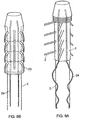
- Figure 1 shows a cover (1) according to the present invention, the cover comprises a number of projecting elements (2) in the form of bristles, moulded at an acute angle with respect to the longitudinal axis of the cover to the outer surface (3) of the elongate tubular member.
- Figure 1 shows the projecting elements in their resting position and the tips pointing towards the proximal end (6).
- the projecting elements (2) are moulded at their base to form a raised portion or bump (4).
- a small air pocket is formed beneath the raised portion or bump (4) on the inner surface (7) of the cover which allows for flexibility of the projecting elements about their base in use and especially when negotiating the confines of a body passage.
- the projecting elements are angled, at rest in the so called first position, to around 45° to 65° towards the proximal end (6) of the cover and with respect to a central longitudinal axis of the cover and, in a forward or distal movement within a body passage once the endoscope or enteroscope has been inserted into the hollow (8) of the cover, the projecting elements are flattened so as to be approximately parallel to the said longitudinal axis with the projecting elements tips pointing towards the proximal end (6). This is the second position.
- the projecting elements are fanned out or expanded into a third position when the covered scope is withdrawn in a proximal movement.
- the endoscopist can apply the air suction means to withdraw air from the body passage causing the body passage wall to partially collapse about the projecting elements (2) and be drawn into the spaces (3) between the individual projecting elements and the spaces between rings and rows of rings of projecting elements.
- the wall of the body passage is gripped and wrapped around the cover, if further forward or distal movement is applied the body passage wall remains gripped by the projecting elements and effectively bunches up or concertinas in the proximal area thereby allowing the distal end to move forward and overcome the looping or bend obstacle.
- the projecting elements (2) are capable of flicking or flipping over past the critical point of maximum inflexion at 90° so that the tips point towards the distal end (5) in a so called fourth position, making withdrawal of the device through the relevant orifice more comfortable for the patient.
- they may be flattened against the cover main body as depicted in Figure 9B as described herein after.
- endoscopists have reported that the cover of the invention remains in position on the flexible medical scoping device shaft and that the projecting elements do not impede the periphery of the visual field.
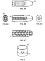
- Projecting elements may be in form of bristles ( Figure 8A ), fins or paddles ( Figure 8B ), cones ( Figure 8C ), bulbs, stalks or buds ( Figure 8D ) or any other flexible projection ( Figure 8E ).
- the projecting elements are provided in rings, typically of about 1 to 10 rings and more typically of two rings in uniform circumferential formation and evenly spaced apart with projecting elements being of a marginally shorter length in the first (distal end (5)) and last (proximal end (6)) rows.
- the cover is provided with several apertures (16) which are capable of fitting over rods provided on the applicator.
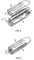
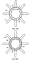
- Figure 2 shows a transverse section through the cover that has bristle type projecting elements.
- the distal end (5) of the cover is seen in greater detail.
- the distal end comprises a head (14) and a profiled end region (9, 10) over which a transparent cap (13) may be placed and held in position by clips (11, 12) or the like.
- This distal region is the end that is furthest in the patient and provides the light and lens through which the endoscopist can observe the body passage.
- the cap (13) is provided with the cover or may be placed in the applicator and the scope is inserted through the cover and caused to engage with the cap in site.
- the end cap is an optional additional feature which can be provided if desired with either the cover or the applicator.
- FIG. 4 shows a disassembled applicator and the securing means (19) of the casings (17, 18) in the form of rods which are inserted into apertures (16) of the proximal end of the cover.
- an end cap can be held in place at the distal end.
- the casings are fitted together by any suitable means and the cover held in position within the shell or casing.
- Figure 6A shows a top view of an assembled casing and Figure 6B shows a side view with the cover in place inside, Figure 6C shows a top view of a disassembled applicator and cover, Figure 6D shows a proximal end view with the apertures of the cover over the rods stretching the cover to form an interior space 20 through which the scope is inserted and Figure 6E shows a distal end view with the viewing hole which may also include the end cap.
- a kit of parts which may optionally include a viewing means attachment (20) optionally provided with a portal (21) for removing under suction any excess fluid ( Figure 7 ).
- the cover is provided with a projecting element closure means (23) typically in the form of a sleeve ( Figures 9A and 9B ).
- a projecting element closure means typically in the form of a sleeve.
- An alternative cover is provided with slits or gaps (28) running in a longitudinal direction and between the distal (A) and proximal (B) regions of the cover, and provided with an over cuff (25).
- the over cuff itself is also provided with slits or gaps (30) between its proximal and distal ends that are of approximately commensurate dimensions as the slits or gaps in the cover so that, when the over cuff is placed over the cover, the slits or gaps in both the cover and over cuff are aligned, providing continuous spaces (29) through both items whilst at each of the distal (A) and proximal (B) ends the cover and over-cuff have continuous rings (31 and 32).
- FIG. 10A shows a plan view of a cover and over cuff (25).
- the over cuff has a snug fit over the cover and is typically constructed of a polycarbonate or other plastics material, projecting elements (2) protrude outwardly between strips (26) of the over cuff and at the distal tip the over cuff it marginally overlaps the cover providing a rim (27) around hollow (8).
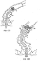
- the medical scoping device distal tip with the cover and over cuff (3, 25) is inserted via the anus (34) into the colon of an individual under investigation.
- the projecting elements are moved from an at rest position, referred herein before as the first position to a second position where they are flattened towards the medical scoping device shaft the so called second position ( Figure 12A ).
- the distal end tip of the medical scoping comprises a channel (37) through which a light source, image relaying mean and air suction is supplied.
- the projecting elements are designed to collapse into the device during insertion through the anus. This exposes the smooth low friction surface of the cover and over cuff to the mucosa to aid intubation.
- the flexible shaft (33) of the medical scoping device is advanced in a distal direction through the colon towards the bend or loop region (36) of the of the colon ( Figure 12B ) whilst insufflatting the colon immediately forwards of the distal tip.
- the projecting elements once passed the anus revert to their resting first position.
- the scope passes further up the colon and encounters the loop region the projecting elements engage with the colon wall in a soft grip (third position where the projecting elements fan out and the endoscopist can perform a controlled proximal withdrawal flattening the colonic folds for good visualisation ( Figure 12C ).
- the distal row of longer projecting elements is designed to open the colonic lumen for close inspection.
- the cover of the present invention provides distinct improvements. Improved visulaisation is important for identifying small pre-malignant and malignant lesions that might be tucked out of sight when performing conventional endoscopy. Visualisation is further enhanced when using the cover of the present invention, especially with wide vision endoscopes.
- the projecting elements of the device gently stabilise the tip of the scoping device within the lumen of the colon or small intestine immediately prior to and during therapeutic procedures.
- This has the advantage of permitting the endoscopist the reassurance that the tip will remain in position from the stage of visualising a lesion or polyp until completion of the therapeutic procedure.
- the distal row of the projecting elements are designed to flare outwards on withdrawal. They keep the instrument tip in the central part of the bowel lumen as the instrument moves backwards, gently holding the mucosa to prevent the tip from flipping backwards, they maintain position during therapy and improve all-round visualisation. During extubation they evert the folds enabling their proximal surface to be viewed.
- the endoscopist can apply air suction so that the colon wall (38) collapses onto the shaft (3) and into the spaces between adjacent rings of projecting elements (39), the projecting elements still being in the third position ( Figure 12D ).
- the colon wall concertinas about the shaft (3) and the endoscopist can then cease suction so that the colon wall straightens and the scope can be further advanced.
- the projecting elements can flip over to the fourth position so that the scope can be comfortably withdrawn.
- the cover of the present invention is designed to provide controlled extubation.
- the colonoscope tip suddenly to slip backwards. This happens especially when passing a bend or flexure and the "missed" area then has to be re-intubated, sometimes with the creation of a painful loop.
- the long, soft, distal projecting elements of the present invention prevent sudden tip slippage and hold the tip in the centre of the colonic lumen providing both control and good visualisation as the endoscope is withdrawn.
Landscapes
- Health & Medical Sciences (AREA)
- Life Sciences & Earth Sciences (AREA)
- Surgery (AREA)
- Heart & Thoracic Surgery (AREA)
- Veterinary Medicine (AREA)
- Public Health (AREA)
- General Health & Medical Sciences (AREA)
- Animal Behavior & Ethology (AREA)
- Engineering & Computer Science (AREA)
- Biomedical Technology (AREA)
- Biophysics (AREA)
- Medical Informatics (AREA)
- Physics & Mathematics (AREA)
- Molecular Biology (AREA)
- Radiology & Medical Imaging (AREA)
- Pathology (AREA)
- Optics & Photonics (AREA)
- Nuclear Medicine, Radiotherapy & Molecular Imaging (AREA)
- Anesthesiology (AREA)
- Hematology (AREA)
- Pulmonology (AREA)
- Endoscopes (AREA)
- Materials For Medical Uses (AREA)
- Closures For Containers (AREA)
- Surgical Instruments (AREA)
Claims (16)
- Abdeckung (1) für die Welle einer Vorrichtung für eine medizinische Untersuchung (33), wobei die Abdeckung ein längliches rohrförmiges Element (3) umfasst und für die Anwendung über eine distale Spitze der Welle einer Vorrichtung für eine medizinische Untersuchung angeordnet ist, wobei sich die Abdeckung mindestens entlang eines Teils der Länge eines distalen Endes der Welle ausdehnt, wobei das rohrförmige Element eine Innenfläche (7), wovon mindestens ein Teil die Welle greift und die Abdeckung an Ort und Stelle hält, und eine Außenfläche umfasst, die eine Vielzahl beabstandeter abstehender Elemente (2) umfasst, dadurch gekennzeichnet, dass die beabstandeten abstehenden Elemente an einer Außenfläche des länglichen rohrförmigen Elements angelenkt und befestigt sind, wobei jedes abstehende Element eine Spitze und eine Basis aufweist, wobei die abstehenden Elemente über ihre angelenkten Basen in einem Winkel von zwischen 0°, wobei die Spitzen der abstehenden Elemente in Richtung eines proximalen Endes der Vorrichtung für eine medizinische Untersuchung zeigen, bis zu einem Winkel von 170-180° beweglich sind, wobei die Spitzen der abstehenden Elemente in Richtung des distalen Endes der Vorrichtung für eine medizinische Untersuchung zeigen oder eines beliebigen Winkels zwischen 0 bis 170-180°, und wobei die abstehenden Elemente (2) zwischen einer ersten Ruheposition in eine zweite Position, wobei die Spitze des abstehenden Elements im Wesentlichen parallel zu einer Längsachse der Vorrichtung für eine medizinische Untersuchung (33) ist, und in eine dritte Position beweglich sind, die in einem Winkel ungefähr senkrecht zu der Längsachse der Welle der Vorrichtung für eine medizinische Untersuchung ist, sodass die abstehenden Elemente aufgefächert sind, um eine Lumenwand eines Körperabschnitts zu berühren und abzustützen und zu dilatieren, in welchen die Vorrichtung für eine medizinische Untersuchung eingeführt wurde, wobei die abstehenden Elemente über die dritte Position hinaus in eine vierte Position beweglich sind, wobei sie an einem kritischen Punkt umschnappen, sodass die Spitzen der abstehenden Elemente in Richtung des distalen Endes der Vorrichtung für eine medizinische Untersuchung zeigen, sodass die Vorrichtung für eine medizinische Untersuchung durch die Öffnung entnommen werden kann, in welche sie ursprünglich eingeführt wurde.
- Abdeckung entweder nach Anspruch 1, wobei die Befestigung der abstehenden Elemente an der Außenfläche des länglichen rohrförmigen Elements entweder durch integrales Formen damit oder durch Gießen daran erfolgt.
- Abdeckung nach einem beliebigen der vorhergehenden Ansprüche, wobei die Abdeckung für die Anwendung über die Welle der Vorrichtung für eine medizinische Untersuchung angeordnet ist, um sie zu umgeben und sich entlang mindestens eines Spitzenbereichs der Welle auszudehnen.
- Abdeckung nach einem beliebigen der vorhergehenden Ansprüche, wobei die abstehenden Elemente (2) in der Form von Borsten, Dornen, Stacheln, Lamellen, Keilen, Schaufeln oder Kegeln vorliegen und so angeordnet sind, dass sie sich nach außen und weg von der Außenfläche des länglichen rohrförmigen Elements ausdehnen.
- Abdeckung nach einem beliebigen der vorhergehenden Ansprüche, wobei die abstehenden Elemente zylindrisch, kegelförmig oder verjüngt sind.
- Abdeckung nach einem beliebigen der vorhergehenden Ansprüche, wobei der mindestens eine Teil der Innenfläche (7) des rohrförmigen Elements, der die Welle greift und die Abdeckung an Ort und Stelle hält, entweder den proximalen und distalen Endbereichen des rohrförmigen Elements oder der gesamten Innenfläche des rohförmigen Elements entspricht.
- Abdeckung nach einem beliebigen der vorhergehenden Ansprüche, wobei das längliche rohrförmige Element entweder ein zusammenhängendes rohrförmiges Element ist oder alternativ mit Schlitzen, Kanten oder Lücken (30) ausgestattet ist, die in einer Längsrichtung und parallel zu der Längsachse der Vorrichtung für eine medizinische Untersuchung verlaufen, optional wobei die Anzahl der Schlitze oder Lücken zu der Anzahl der abstehenden Elemente (2) direkt proportional ist und wobei die abstehenden Elemente in den Schlitzen oder Lücken zwischen festen Bestandteilen des rohrförmigen Elements positioniert sind.
- Abdeckung nach einem beliebigen der vorhergehenden Ansprüche, wobei die Länge der abstehenden Elemente entweder/sowohl an den distalen oder/als auch den proximalen Enden der Abdeckung geringfügig kürzer ist.
- Abdeckung nach einem beliebigen Anspruch 8, wobei die abstehenden Elemente, die eine längere Länge aufweisen, biegsamer sind und aus einem weicheren Material gefertigt sind als abstehende Elemente mit einer kürzeren Länge.
- Abdeckung nach einem beliebigen der vorhergehenden Ansprüche, wobei das längliche rohrförmige Element und/oder die abstehenden Elemente aus einem biokompatiblen biegsamen Material gefertigt wird bzw. werden, das aus der Gruppe ausgewählt wird, die Polymere, Kunststoffe, Elastomere, Silizium und Silizium-Elastomer-Materialien und -Kautschuke umfasst.
- Abdeckung nach einem beliebigen der vorhergehenden Ansprüche, wobei die abstehenden Elemente in einer Ruheposition bezüglich der zentralen Längsachse der Welle der Vorrichtung für eine medizinische Untersuchung in einem Winkel zwischen 35° bis 85° spitzwinklig sind.
- Abdeckung nach einem beliebigen der vorhergehenden Ansprüche, die zusätzlich eine Übermanschette (25) umfasst.
- Abdeckung nach Anspruch 12, wobei die Übermanschette über der Abdeckung platziert ist und mit Schlitzen oder Lücken (26) ausgestattet ist, die ungefähr die gleichen Dimensionen aufweisen wie die der Abdeckung (1), sodass die abstehenden Elemente (2) dazu in der Lage sind, durch die ausgerichteten Schlitze oder Lücken (26) herauszuragen.
- Abdeckung entweder nach Anspruch 12 oder 13, wobei die Übermanschette (25) die gleiche oder ungefähr die gleiche Länge aufweist wie die Abdeckung.
- Abdeckung nach einem beliebigen der vorhergehenden Ansprüche, die zusätzlich an dem distalen Ende ein Sichtmittel (20) umfasst, das optional die Form einer transparenten Kunststoffkappe mit offenem Ende aufweist.
- Vorrichtung für eine medizinische Untersuchung, welche die Abdeckung nach einem beliebigen der Ansprüche 1 bis 15 umfasst, die mindestens einen Teil ihrer distalen Welle bildet.
Priority Applications (6)
| Application Number | Priority Date | Filing Date | Title |
|---|---|---|---|
| RS20160068A RS54555B2 (sr) | 2010-05-25 | 2011-05-24 | Pokrivač za medicinski aparat za skopiju |
| SI201130733T SI2575590T2 (sl) | 2010-05-25 | 2011-05-24 | Pokrov za medicinsko preiskovalno napravo |
| HRP20160090TT HRP20160090T4 (hr) | 2010-05-25 | 2011-05-24 | Pokrivač za medicinski aparat za skopiju |
| PL11722861T PL2575590T5 (pl) | 2010-05-25 | 2011-05-24 | Nakładka do medycznego wziernikowego urządzenia |
| EP15169674.7A EP2937034B1 (de) | 2010-05-25 | 2011-05-24 | Abdeckung für eine medizinische skopievorrichtung |
| CY20161100117T CY1117192T1 (el) | 2010-05-25 | 2016-02-12 | Καλυμμα για mia ιατρικη συσκευη σκοπησης |
Applications Claiming Priority (4)
| Application Number | Priority Date | Filing Date | Title |
|---|---|---|---|
| GBGB1008637.9A GB201008637D0 (en) | 2010-05-25 | 2010-05-25 | Covering for a medical scoping device |
| GBGB1101619.3A GB201101619D0 (en) | 2011-01-31 | 2011-01-31 | Covering for a medical scoping device |
| GBGB1107535.5A GB201107535D0 (en) | 2011-05-06 | 2011-05-06 | Covering for a medical scooping device |
| PCT/GB2011/050981 WO2011148172A2 (en) | 2010-05-25 | 2011-05-24 | Covering for a medical scoping device |
Related Child Applications (2)
| Application Number | Title | Priority Date | Filing Date |
|---|---|---|---|
| EP15169674.7A Division-Into EP2937034B1 (de) | 2010-05-25 | 2011-05-24 | Abdeckung für eine medizinische skopievorrichtung |
| EP15169674.7A Division EP2937034B1 (de) | 2010-05-25 | 2011-05-24 | Abdeckung für eine medizinische skopievorrichtung |
Publications (3)
| Publication Number | Publication Date |
|---|---|
| EP2575590A2 EP2575590A2 (de) | 2013-04-10 |
| EP2575590B1 EP2575590B1 (de) | 2015-12-16 |
| EP2575590B2 true EP2575590B2 (de) | 2018-12-26 |
Family
ID=44279541
Family Applications (2)
| Application Number | Title | Priority Date | Filing Date |
|---|---|---|---|
| EP15169674.7A Active EP2937034B1 (de) | 2010-05-25 | 2011-05-24 | Abdeckung für eine medizinische skopievorrichtung |
| EP11722861.9A Active EP2575590B2 (de) | 2010-05-25 | 2011-05-24 | Abdeckung für eine medizinische skopievorrichtungen |
Family Applications Before (1)
| Application Number | Title | Priority Date | Filing Date |
|---|---|---|---|
| EP15169674.7A Active EP2937034B1 (de) | 2010-05-25 | 2011-05-24 | Abdeckung für eine medizinische skopievorrichtung |
Country Status (26)
| Country | Link |
|---|---|
| US (5) | US9808142B2 (de) |
| EP (2) | EP2937034B1 (de) |
| JP (1) | JP5993370B2 (de) |
| KR (1) | KR101849131B1 (de) |
| CN (1) | CN102905608B (de) |
| AU (1) | AU2011256957C1 (de) |
| BR (1) | BR112012030053B1 (de) |
| CA (1) | CA2800198C (de) |
| CY (1) | CY1117192T1 (de) |
| DE (1) | DE202011110721U1 (de) |
| DK (1) | DK2575590T4 (de) |
| ES (2) | ES2562264T5 (de) |
| GB (1) | GB2478081B8 (de) |
| HR (2) | HRP20160090T4 (de) |
| HU (1) | HUE026680T2 (de) |
| MX (1) | MX2012013661A (de) |
| MY (1) | MY184615A (de) |
| PL (1) | PL2575590T5 (de) |
| PT (1) | PT2575590E (de) |
| RS (1) | RS54555B2 (de) |
| RU (1) | RU2566918C2 (de) |
| SG (1) | SG185636A1 (de) |
| SI (2) | SI2937034T1 (de) |
| SM (1) | SMT201600048B (de) |
| WO (1) | WO2011148172A2 (de) |
| ZA (1) | ZA201208828B (de) |
Families Citing this family (80)
| Publication number | Priority date | Publication date | Assignee | Title |
|---|---|---|---|---|
| US8100822B2 (en) | 2004-03-16 | 2012-01-24 | Macroplata Systems, Llc | Anoscope for treating hemorrhoids without the trauma of cutting or the use of an endoscope |
| US10758116B2 (en) | 2009-12-16 | 2020-09-01 | Boston Scientific Scimed, Inc. | System for a minimally-invasive, operative gastrointestinal treatment |
| US9186131B2 (en) | 2009-12-16 | 2015-11-17 | Macroplata, Inc. | Multi-lumen-catheter retractor system for a minimally-invasive, operative gastrointestinal treatment |
| US10531869B2 (en) | 2009-12-16 | 2020-01-14 | Boston Scientific Scimed, Inc. | Tissue retractor for minimally invasive surgery |
| US8932211B2 (en) | 2012-06-22 | 2015-01-13 | Macroplata, Inc. | Floating, multi-lumen-catheter retractor system for a minimally-invasive, operative gastrointestinal treatment |
| US10595711B2 (en) | 2009-12-16 | 2020-03-24 | Boston Scientific Scimed, Inc. | System for a minimally-invasive, operative gastrointestinal treatment |
| ES2874194T3 (es) | 2009-12-16 | 2021-11-04 | Boston Scient Scimed Inc | Disposiciones para realizar una estructura anatómica endoluminal |
| US10966701B2 (en) | 2009-12-16 | 2021-04-06 | Boston Scientific Scimed, Inc. | Tissue retractor for minimally invasive surgery |
| US12376737B1 (en) | 2009-12-16 | 2025-08-05 | Boston Scientific Scimed, Inc. | Tissue retractor for minimally invasive surgery |
| USRE48850E1 (en) | 2009-12-16 | 2021-12-14 | Boston Scientific Scimed, Inc. | Multi-lumen-catheter retractor system for a minimally-invasive, operative gastrointestinal treatment |
| US11344285B2 (en) | 2009-12-16 | 2022-05-31 | Boston Scientific Scimed, Inc. | Multi-lumen-catheter retractor system for a minimally-invasive, operative gastrointestinal treatment |
| US9565998B2 (en) | 2009-12-16 | 2017-02-14 | Boston Scientific Scimed, Inc. | Multi-lumen-catheter retractor system for a minimally-invasive, operative gastrointestinal treatment |
| EP2544580B1 (de) | 2010-03-09 | 2021-07-14 | Smart Medical Systems Ltd | Ballonendoskop und verfahren zu seiner herstellung und verwendung |
| DK2675335T3 (da) | 2011-02-16 | 2022-01-03 | Massachusetts Gen Hospital | Optisk kobler til et endoskop |
| US12471759B2 (en) | 2011-02-16 | 2025-11-18 | The General Hospital Corporation | Optical coupler for an endoscope |
| CN112932386A (zh) * | 2011-03-07 | 2021-06-11 | 智能医疗系统有限公司 | 装备球囊的内窥镜装置及其方法 |
| WO2014042686A1 (en) | 2012-09-14 | 2014-03-20 | Kamler Jan | Ligator and method of use |
| GB2507980B (en) | 2012-11-15 | 2015-06-10 | Rolls Royce Plc | Inspection arrangement |
| WO2014123563A1 (en) * | 2013-02-07 | 2014-08-14 | Endoaid Ltd. | Endoscopic sleeve |
| US10299662B2 (en) * | 2013-02-07 | 2019-05-28 | Endoaid Ltd. | Endoscopic sleeve |
| PT2999552T (pt) | 2013-05-21 | 2018-12-27 | Smart Medical Systems Ltd | Sistema de endoscópico por reprocessamento e respetivo método |
| US20140358089A1 (en) * | 2013-06-04 | 2014-12-04 | Boston Scientific Scimed, Inc. | Vacuum-assisted pancreaticobiliary cannulation |
| WO2015127265A1 (en) * | 2014-02-24 | 2015-08-27 | Visualization Balloons, Llc | Gastrointestinal endoscopy with attachable intestine pleating structures |
| EP3131452A4 (de) * | 2014-04-16 | 2018-01-03 | Visualization Balloons, LLC | Gastrointestinale endoskopie mit darmplissiervorrichtungen und verfahren |
| US9459442B2 (en) | 2014-09-23 | 2016-10-04 | Scott Miller | Optical coupler for optical imaging visualization device |
| JP6683725B2 (ja) * | 2014-11-24 | 2020-04-22 | コンシス メディカル リミテッド.Consis Medical Ltd. | 経路に沿って物品を進めるためのシステム、装置、および方法 |
| CN107105986B (zh) | 2014-12-22 | 2019-11-05 | 智能医疗系统有限公司 | 气囊内窥镜再处理系统和方法 |
| US10835107B2 (en) | 2015-04-03 | 2020-11-17 | Smart Medical Systems Ltd. | Endoscope electro-pneumatic adaptor |
| CN107820409A (zh) | 2015-05-19 | 2018-03-20 | 恩多埃德有限公司 | 具有翼的内窥镜套管 |
| US10548467B2 (en) | 2015-06-02 | 2020-02-04 | GI Scientific, LLC | Conductive optical element |
| EP3313257A4 (de) * | 2015-06-25 | 2019-01-30 | Medivators Inc. | Armatur für eine medizinische skopievorrichtung |
| AU2016297077B2 (en) | 2015-07-21 | 2020-10-22 | GI Scientific, LLC | Endoscope accessory with angularly adjustable exit portal |
| WO2017041052A1 (en) | 2015-09-03 | 2017-03-09 | Neptune Medical | Device for endoscopic advancement through the small intestine |
| JP6884144B2 (ja) * | 2015-10-23 | 2021-06-09 | Hoya株式会社 | 内視鏡頂部の取付け装置 |
| GB201605358D0 (en) * | 2016-03-30 | 2016-05-11 | Meditech Endoscopy Ltd | Instrument tip protector |
| WO2017189855A1 (en) * | 2016-04-27 | 2017-11-02 | President And Fellows Of Harvard College | Anti-fouling endoscopes and uses thereof |
| GB201608380D0 (en) * | 2016-05-12 | 2016-06-29 | Arc Medical Design Ltd | Medical scope accessory, medical scopes comprising the accessory, and use thereof |
| US10980975B2 (en) | 2016-05-19 | 2021-04-20 | Ibex Technologies Ltd. | System, device and method for advancing an article along a path |
| JP6956116B2 (ja) * | 2016-07-01 | 2021-10-27 | ボストン サイエンティフィック サイムド,インコーポレイテッドBoston Scientific Scimed,Inc. | 医療器具を搬送する装置及び方法 |
| WO2018035452A1 (en) | 2016-08-18 | 2018-02-22 | Neptune Medical | Device and method for enhanced visualization of the small intestine |
| US10709313B2 (en) | 2016-09-21 | 2020-07-14 | NCI, Inc. | Surgical instrument inspection system |
| CN106343941B (zh) * | 2016-11-03 | 2017-09-05 | 沈阳尚贤医疗系统有限公司 | 内窥镜套筒 |
| IT201600124851A1 (it) * | 2016-12-12 | 2018-06-12 | Alessandro Budano | Dispositivo per endoscopia |
| EP3562374A1 (de) | 2016-12-30 | 2019-11-06 | Boston Scientific Scimed, Inc. | System zur minimal-invasiven behandlung in einem körperlumen |
| CN110913773B (zh) | 2017-03-18 | 2023-03-28 | 波士顿科学国际有限公司 | 用于体腔内的微创治疗的系统 |
| DE102017106846A1 (de) * | 2017-03-30 | 2018-10-04 | Aesculap Ag | Chirurgisches Retraktorsystem mit einem Retraktor und einem Extraktor sowie ein torsionsbeaufschlagendes chirurgisches Instrument |
| JP6688937B2 (ja) | 2017-04-19 | 2020-04-28 | Hoya株式会社 | 内視鏡頂部の取り付け装置 |
| USD870281S1 (en) | 2017-05-26 | 2019-12-17 | Medivators Inc. | Fitting for an endoscope device having a tab |
| USD870280S1 (en) | 2017-05-26 | 2019-12-17 | Medivators Inc. | Fitting for an endoscope device having protuberances |
| EP3654822B1 (de) | 2017-07-20 | 2023-11-15 | Neptune Medical Inc. | Dynamisch versteiftes überrohr |
| JP6725763B2 (ja) * | 2017-08-01 | 2020-07-22 | 株式会社シード | 内視鏡用フード |
| WO2019104329A1 (en) * | 2017-11-27 | 2019-05-31 | Optecks, Llc | Medical three-dimensional (3d) scanning and mapping system |
| CN107928606B (zh) * | 2017-12-11 | 2019-04-19 | 荣佳(惠州)医疗器械制造有限公司 | 一种医疗内窥镜套筒 |
| CN108261174B (zh) * | 2018-03-13 | 2024-06-07 | 南微医学科技股份有限公司 | 一种内窥镜端帽 |
| EP3801187B1 (de) | 2018-05-31 | 2024-02-07 | Neptune Medical Inc. | Vorrichtung zur verbesserten visualisierung des dünndarms |
| EP3823711A4 (de) | 2018-07-19 | 2022-05-18 | Neptune Medical Inc. | Dynamisch versteifende medizinische kompositstrukturen |
| RU188717U1 (ru) * | 2018-10-26 | 2019-04-22 | Общество с ограниченной ответственностью "НПФ "ЭлМед" | Устройство для нейрохирургического эндоскопического вмешательства |
| WO2020138537A1 (ko) * | 2018-12-27 | 2020-07-02 | 경상대학교병원 | 의료용 석션기구 |
| US11013530B2 (en) | 2019-03-08 | 2021-05-25 | Medos International Sarl | Surface features for device retention |
| US11793392B2 (en) | 2019-04-17 | 2023-10-24 | Neptune Medical Inc. | External working channels |
| WO2020214221A1 (en) | 2019-04-17 | 2020-10-22 | Neptune Medical Inc. | Dynamically rigidizing composite medical structures |
| US12527458B2 (en) | 2019-08-27 | 2026-01-20 | Alpine Medical Devices, Llc | Telescopic attachment for endoscope |
| US11832789B2 (en) | 2019-12-13 | 2023-12-05 | Boston Scientific Scimed, Inc. | Devices, systems, and methods for minimally invasive surgery in a body lumen |
| EP4093261A4 (de) * | 2020-03-05 | 2023-06-21 | Alexander Huelsen | Endoskophaube |
| US11744443B2 (en) | 2020-03-30 | 2023-09-05 | Neptune Medical Inc. | Layered walls for rigidizing devices |
| WO2021202809A1 (en) * | 2020-04-01 | 2021-10-07 | GI Scientific, LLC | Systems and methods for diagnosing and/or treating patients |
| US12121677B2 (en) | 2021-01-29 | 2024-10-22 | Neptune Medical Inc. | Devices and methods to prevent inadvertent motion of dynamically rigidizing apparatuses |
| US12167834B2 (en) | 2021-02-03 | 2024-12-17 | Korea Advanced Institute Of Science And Technology | Colon linearizing device, colon linearizing system including the same and method of manufacturing the colon linearizing device |
| EP4070715A1 (de) * | 2021-02-10 | 2022-10-12 | Meilleur Co., Ltd. | Kameraabdeckung |
| CA3211622A1 (en) | 2021-03-10 | 2022-09-15 | Neal Tanner | Control of robotic dynamically rigidizing composite medical structures |
| US20220395171A1 (en) * | 2021-06-15 | 2022-12-15 | Arthrex, Inc. | Surgical camera system |
| KR20230017639A (ko) * | 2021-07-28 | 2023-02-06 | 고지환 | 내시경 캡 |
| WO2023122767A2 (en) * | 2021-12-22 | 2023-06-29 | Neptune Medical Inc. | Methods and apparatuses for reducing curvature of a colon |
| US12564312B2 (en) | 2022-04-19 | 2026-03-03 | Neptune Medical Inc. | Managing and manipulating a long length robotic endoscope |
| KR20250003955A (ko) | 2022-04-27 | 2025-01-07 | 넵튠 메디컬 인코포레이티드 | 내시경용 위생 외장 |
| US20240008720A1 (en) * | 2022-07-06 | 2024-01-11 | Gyrus Acmi, Inc. D/B/C Olympus Surgical Technologies America | Elongate endoscopic covering |
| AU2024338348A1 (en) | 2023-09-07 | 2026-03-19 | Neptune Medical Inc. | Pressure rigidization apparatuses and methods |
| WO2025072977A1 (en) | 2023-09-28 | 2025-04-03 | Neptune Medical Inc. | Telescoping robot |
| GB2636995A (en) * | 2024-01-02 | 2025-07-09 | Keymed Medical & Industrial Equipment Ltd | Medical device accessory |
| CN120000339A (zh) * | 2025-04-21 | 2025-05-16 | 中国人民解放军总医院海南医院 | 一种消化内镜辅助机械手 |
Family Cites Families (84)
| Publication number | Priority date | Publication date | Assignee | Title |
|---|---|---|---|---|
| FR1278965A (fr) * | 1961-01-27 | 1961-12-15 | Maison Drapier | Perfectionnements aux cathéters médicaux |
| US3717151A (en) * | 1971-03-11 | 1973-02-20 | R Collett | Flesh penetrating apparatus |
| US4207872A (en) * | 1977-12-16 | 1980-06-17 | Northwestern University | Device and method for advancing an endoscope through a body passage |
| US5018509A (en) * | 1989-02-21 | 1991-05-28 | Olympus Optical Co., Ltd. | Endoscope insertion controlling apparatus |
| JPH0777576B2 (ja) * | 1991-03-27 | 1995-08-23 | 了司 服部 | 内視鏡の付属品及び内視鏡 |
| DE4137303C2 (de) * | 1991-11-13 | 1993-12-02 | Rheintechnik Weiland & Kaspar | Verfahren zur Messung der elektrischen Leitfähigkeit von Körperflüssigkeiten, sowie hierbei verwandte Meßsonde |
| US5259366A (en) * | 1992-11-03 | 1993-11-09 | Boris Reydel | Method of using a catheter-sleeve assembly for an endoscope |
| US5653690A (en) * | 1992-12-30 | 1997-08-05 | Medtronic, Inc. | Catheter having a balloon with retention enhancement |
| JP2855246B2 (ja) * | 1993-09-08 | 1999-02-10 | 日野自動車工業株式会社 | ミリ波送受信装置、ミリ波受信装置、およびミリ波送受信用アンテナ |
| US5505686A (en) | 1994-05-05 | 1996-04-09 | Imagyn Medical, Inc. | Endoscope with protruding member and method of utilizing the same |
| JP3178321B2 (ja) | 1995-11-24 | 2001-06-18 | 富士写真光機株式会社 | 体腔内挿入部材の軟質部保護具 |
| US5817062A (en) | 1996-03-12 | 1998-10-06 | Heartport, Inc. | Trocar |
| GB9610765D0 (en) * | 1996-05-23 | 1996-07-31 | Axon Anthony T R | Improvements in or relating to endoscopes |
| AU8415498A (en) | 1997-04-21 | 1998-11-13 | Barry David Brighton | An endoscopic apparatus |
| US6589213B2 (en) | 1997-12-12 | 2003-07-08 | Wilson-Cook Medical Incorporated | Body canal intrusion instrumentation having bi-directional coefficient of surface friction with body tissue |
| US6406425B1 (en) | 1998-06-22 | 2002-06-18 | Origin Medasystems | Cannula-based irrigation system and method |
| US5916145A (en) | 1998-08-07 | 1999-06-29 | Scimed Life Systems, Inc. | Device and method of using a surgical assembly with mesh sheath |
| WO2000013736A1 (en) | 1998-09-03 | 2000-03-16 | H.D.S. Systems, Ltd. | Finned-tip flow guided catheters |
| WO2000041614A1 (en) | 1999-01-19 | 2000-07-20 | Tyco Healthcare Group Lp | Sheath and applicator for surgical instrument |
| DE10027447A1 (de) | 1999-07-22 | 2001-02-01 | Univ Ilmenau Tech | Fluidischer, peristaltischer Antrieb |
| US6858005B2 (en) | 2000-04-03 | 2005-02-22 | Neo Guide Systems, Inc. | Tendon-driven endoscope and methods of insertion |
| US6988986B2 (en) | 2002-11-25 | 2006-01-24 | G. I. View | Self-propelled imaging system |
| AU2002317466B2 (en) | 2001-07-12 | 2008-02-28 | Given Imaging Ltd | Device and method for examining a body lumen |
| JP4804664B2 (ja) | 2001-07-19 | 2011-11-02 | オリンパス株式会社 | 内視鏡挿入補助具 |
| US6913610B2 (en) | 2001-10-16 | 2005-07-05 | Granit Medical Innovations, Inc. | Endoscopic retractor instrument and associated method |
| KR100417163B1 (ko) | 2001-11-12 | 2004-02-05 | 한국과학기술연구원 | 마이크로 캡슐형 로봇 |
| JP2003180611A (ja) * | 2001-12-18 | 2003-07-02 | Olympus Optical Co Ltd | 内視鏡挿入補助具 |
| JP3826045B2 (ja) | 2002-02-07 | 2006-09-27 | オリンパス株式会社 | 内視鏡用フード |
| ES1051891Y (es) | 2002-04-25 | 2003-02-16 | Francisco Hernandez Altemir S | Tubo nasotraqueal para exploracion e intubacion. |
| JP2003339631A (ja) * | 2002-05-23 | 2003-12-02 | Olympus Optical Co Ltd | 内視鏡挿入補助具 |
| US6979290B2 (en) | 2002-05-30 | 2005-12-27 | The Board Of Trustees Of The Leland Stanford Junior University | Apparatus and methods for coronary sinus access |
| US6790173B2 (en) | 2002-06-13 | 2004-09-14 | Usgi Medical, Inc. | Shape lockable apparatus and method for advancing an instrument through unsupported anatomy |
| US6679836B2 (en) * | 2002-06-21 | 2004-01-20 | Scimed Life Systems, Inc. | Universal programmable guide catheter |
| JP3791916B2 (ja) | 2002-10-11 | 2006-06-28 | オリンパス株式会社 | 内視鏡用先端フード部材 |
| US6958035B2 (en) | 2002-10-15 | 2005-10-25 | Dusa Pharmaceuticals, Inc | Medical device sheath apparatus and method of making and using same |
| US7122003B2 (en) | 2003-04-16 | 2006-10-17 | Granit Medical Innovations, Llc | Endoscopic retractor instrument and associated method |
| US7473220B2 (en) | 2003-08-04 | 2009-01-06 | Medcanica, Inc. | Surgical port device |
| ITMI20032278A1 (it) | 2003-11-21 | 2005-05-22 | Ethicon Endo Surgery Inc | Dispositivo di diagnosi |
| US7195592B2 (en) | 2004-01-27 | 2007-03-27 | Sundaram Ravikumar | Surgical retractor apparatus for use with a surgical port |
| JP3877075B2 (ja) | 2004-01-28 | 2007-02-07 | 有限会社エスアールジェイ | 内視鏡装置 |
| JP2006026344A (ja) | 2004-07-12 | 2006-02-02 | Toshifumi Hayakawa | 大腸内視鏡挿入用伸展脚式移動シース |
| US20060025653A1 (en) | 2004-07-28 | 2006-02-02 | Phonak Ag | Structure for probe insertion |
| JP4648712B2 (ja) * | 2005-01-14 | 2011-03-09 | Hoya株式会社 | 大腸挿入用内視鏡の先端部 |
| US20060258909A1 (en) | 2005-04-08 | 2006-11-16 | Usgi Medical, Inc. | Methods and apparatus for maintaining sterility during transluminal procedures |
| US20060287666A1 (en) | 2005-06-15 | 2006-12-21 | Usgi Medical Inc. | Apparatus and methods for endoluminal advancement |
| US20070015965A1 (en) * | 2005-07-13 | 2007-01-18 | Usgi Medical Inc. | Methods and apparatus for colonic cleaning |
| JP4804864B2 (ja) | 2005-10-07 | 2011-11-02 | 日立オムロンターミナルソリューションズ株式会社 | 紙幣取扱システム |
| EP1772104A2 (de) | 2005-10-07 | 2007-04-11 | Tsion Israel Medical Systems Ltd. | Vorrichtung zum Schutz gegen Kontamination |
| US20070149850A1 (en) | 2005-12-22 | 2007-06-28 | Spivey James T | Endoscope endcap attachment tool |
| US8092371B2 (en) | 2006-01-13 | 2012-01-10 | Olympus Medical Systems Corp. | Medical treatment endoscope |
| EP1983882A2 (de) | 2006-01-30 | 2008-10-29 | Vision Sciences Inc. | Steuerbares endoskop |
| US8016794B2 (en) | 2006-03-09 | 2011-09-13 | Interrad Medical, Inc. | Anchor device and method |
| US8915842B2 (en) | 2008-07-14 | 2014-12-23 | Ethicon Endo-Surgery, Inc. | Methods and devices for maintaining visibility and providing irrigation and/or suction during surgical procedures |
| US8348889B2 (en) * | 2006-06-01 | 2013-01-08 | Arash Salemi | Self-retaining and fluid delivery catheter |
| JP4885640B2 (ja) * | 2006-08-01 | 2012-02-29 | オリンパスメディカルシステムズ株式会社 | 内視鏡用挿入補助具 |
| EP2056707A4 (de) | 2006-09-01 | 2010-05-26 | Nidus Medical Llc | Gewebevisualisierungsvorrichtung mit mehrteiligem rahmen |
| WO2008033728A2 (en) | 2006-09-11 | 2008-03-20 | Pluromed, Inc. | Atraumatic occlusion balloons and skirts, and methods of use thereof |
| US8025656B2 (en) | 2006-11-07 | 2011-09-27 | Hologic, Inc. | Methods, systems and devices for performing gynecological procedures |
| US20090306472A1 (en) | 2007-01-18 | 2009-12-10 | Filipi Charles J | Systems and techniques for endoscopic dilation |
| GB0706783D0 (en) | 2007-04-05 | 2007-05-16 | Systems Medical Ltd | Apparatus for deploying endoscope |
| WO2009011881A1 (en) | 2007-07-18 | 2009-01-22 | Barosense, Inc. | Overtube introducer for use in endoscopic bariatric surgery |
| JP2009045141A (ja) | 2007-08-16 | 2009-03-05 | Fujifilm Corp | 内視鏡用挿入補助具及び内視鏡 |
| JP5284628B2 (ja) | 2007-11-28 | 2013-09-11 | オリンパスメディカルシステムズ株式会社 | 内視鏡用処置システム |
| US9050004B2 (en) | 2007-12-07 | 2015-06-09 | Socorro Medical, Inc. | Endoscopic system for accessing constrained surgical spaces |
| EP2244641B1 (de) | 2008-01-11 | 2014-01-01 | Boston Scientific Scimed, Inc. | Gerät zur verankerung eines endoskops |
| US20090287052A1 (en) | 2008-05-19 | 2009-11-19 | Boston Scientific Scimed, Inc. | Biopsy Cap Attachment and Integrated Locking Device |
| US8337394B2 (en) | 2008-10-01 | 2012-12-25 | Ethicon Endo-Surgery, Inc. | Overtube with expandable tip |
| CN102123652B (zh) | 2009-02-18 | 2013-09-11 | 奥林巴斯医疗株式会社 | 内窥镜插入装置 |
| US8568308B2 (en) | 2009-08-14 | 2013-10-29 | Alan M. Reznik | Customizable, self holding, space retracting arthroscopic/endoscopic cannula system |
| WO2011039756A1 (en) | 2009-10-01 | 2011-04-07 | Gi Motions Ltd. | Method and apparatus for endoscope advancement |
| ES2341086B2 (es) | 2010-01-29 | 2011-01-03 | Nicolas Anthony Costovici | Cateter para la practica de colonoscopia por imagen. |
| CN102939042B (zh) | 2010-05-11 | 2015-07-29 | 库克医学技术有限责任公司 | 胆道进入鞘管 |
| EP2668887B1 (de) | 2011-04-08 | 2016-01-13 | Olympus Corporation | Endoskop |
| FR2977135B1 (fr) | 2011-06-29 | 2014-10-10 | Univ Paris Curie | Instrument endoscopique a pied d'appui |
| US9066653B2 (en) | 2012-03-08 | 2015-06-30 | The Cleveland Clinic Foundation | Devices, systems, and methods for visualizing and manipulating tissue |
| JP5975257B2 (ja) | 2012-03-08 | 2016-08-23 | 国立大学法人 香川大学 | 領域確保用器具および領域確保用器具を備えた内視鏡 |
| US9095299B2 (en) | 2012-04-23 | 2015-08-04 | Stephen P. RAY | Surgical sleeve suction retractor |
| WO2013190543A1 (en) | 2012-06-17 | 2013-12-27 | Gi Motions, Ltd. | Method and apparatus for device advancement within a lumen |
| EP2898817B1 (de) | 2012-09-19 | 2017-11-01 | Olympus Corporation | Hilfsvorrichtung für einsatz/extraktion |
| US9717399B2 (en) | 2012-09-28 | 2017-08-01 | Endopodium, Inc. | Endoscope with multifunctional extendible arms and endoscopic instrument with integrated image capture for use therewith |
| CN103945753B (zh) | 2012-10-10 | 2016-01-20 | 奥林巴斯株式会社 | 处理器具 |
| EP2915475B1 (de) | 2012-11-05 | 2018-06-20 | Olympus Corporation | Vorrichtung zur unterstützung einer einsetzung und entnahme sowie endoskop mit dieser vorrichtung zur unterstützung einer einsetzung und entnahme |
| WO2014123563A1 (en) | 2013-02-07 | 2014-08-14 | Endoaid Ltd. | Endoscopic sleeve |
| JP2014212835A (ja) | 2013-04-23 | 2014-11-17 | ショーダテクトロン株式会社 | 内視鏡用フードおよび同内視鏡用フードを備えた内視鏡 |
-
2011
- 2011-05-24 ES ES11722861T patent/ES2562264T5/es active Active
- 2011-05-24 KR KR1020127030902A patent/KR101849131B1/ko active Active
- 2011-05-24 MY MYPI2012005000A patent/MY184615A/en unknown
- 2011-05-24 SI SI201131977T patent/SI2937034T1/sl unknown
- 2011-05-24 ES ES15169674T patent/ES2873206T3/es active Active
- 2011-05-24 HR HRP20160090TT patent/HRP20160090T4/hr unknown
- 2011-05-24 DE DE202011110721.7U patent/DE202011110721U1/de not_active Expired - Lifetime
- 2011-05-24 EP EP15169674.7A patent/EP2937034B1/de active Active
- 2011-05-24 RU RU2012150742/14A patent/RU2566918C2/ru active
- 2011-05-24 PL PL11722861T patent/PL2575590T5/pl unknown
- 2011-05-24 AU AU2011256957A patent/AU2011256957C1/en active Active
- 2011-05-24 SG SG2012084729A patent/SG185636A1/en unknown
- 2011-05-24 SI SI201130733T patent/SI2575590T2/sl unknown
- 2011-05-24 CA CA2800198A patent/CA2800198C/en active Active
- 2011-05-24 DK DK11722861.9T patent/DK2575590T4/en active
- 2011-05-24 EP EP11722861.9A patent/EP2575590B2/de active Active
- 2011-05-24 WO PCT/GB2011/050981 patent/WO2011148172A2/en not_active Ceased
- 2011-05-24 HU HUE11722861A patent/HUE026680T2/en unknown
- 2011-05-24 MX MX2012013661A patent/MX2012013661A/es unknown
- 2011-05-24 CN CN201180026078.5A patent/CN102905608B/zh active Active
- 2011-05-24 GB GB201108723A patent/GB2478081B8/en active Active
- 2011-05-24 US US13/699,172 patent/US9808142B2/en active Active
- 2011-05-24 RS RS20160068A patent/RS54555B2/sr unknown
- 2011-05-24 PT PT117228619T patent/PT2575590E/pt unknown
- 2011-05-24 BR BR112012030053-9A patent/BR112012030053B1/pt active IP Right Grant
- 2011-05-24 JP JP2013511740A patent/JP5993370B2/ja active Active
-
2012
- 2012-11-22 ZA ZA2012/08828A patent/ZA201208828B/en unknown
-
2016
- 2016-02-12 CY CY20161100117T patent/CY1117192T1/el unknown
- 2016-02-16 SM SM201600048T patent/SMT201600048B/xx unknown
-
2017
- 2017-09-15 US US15/705,390 patent/US10722103B2/en active Active
-
2020
- 2020-06-18 US US16/904,776 patent/US11382494B2/en active Active
-
2021
- 2021-05-18 HR HRP20210797TT patent/HRP20210797T1/hr unknown
-
2022
- 2022-05-19 US US17/748,176 patent/US12178396B2/en active Active
-
2024
- 2024-11-21 US US18/955,506 patent/US20250072725A1/en active Pending
Also Published As
Similar Documents
| Publication | Publication Date | Title |
|---|---|---|
| US12178396B2 (en) | Covering for a medical scoping device | |
| EP2953518B1 (de) | Endoskophülse | |
| AU2018100900A4 (en) | Covering for a medical scoping device | |
| AU2013263814B2 (en) | Covering for a medical scoping device | |
| HK1179139B (en) | Covering for a medical scoping device |
Legal Events
| Date | Code | Title | Description |
|---|---|---|---|
| PUAI | Public reference made under article 153(3) epc to a published international application that has entered the european phase |
Free format text: ORIGINAL CODE: 0009012 |
|
| 17P | Request for examination filed |
Effective date: 20121220 |
|
| AK | Designated contracting states |
Kind code of ref document: A2 Designated state(s): AL AT BE BG CH CY CZ DE DK EE ES FI FR GB GR HR HU IE IS IT LI LT LU LV MC MK MT NL NO PL PT RO RS SE SI SK SM TR |
|
| DAX | Request for extension of the european patent (deleted) | ||
| REG | Reference to a national code |
Ref country code: HK Ref legal event code: DE Ref document number: 1179139 Country of ref document: HK |
|
| RIN1 | Information on inventor provided before grant (corrected) |
Inventor name: AXON, ANTHONY Inventor name: AXON, PATRICK |
|
| 17Q | First examination report despatched |
Effective date: 20140723 |
|
| GRAP | Despatch of communication of intention to grant a patent |
Free format text: ORIGINAL CODE: EPIDOSNIGR1 |
|
| INTG | Intention to grant announced |
Effective date: 20150318 |
|
| GRAS | Grant fee paid |
Free format text: ORIGINAL CODE: EPIDOSNIGR3 |
|
| GRAA | (expected) grant |
Free format text: ORIGINAL CODE: 0009210 |
|
| AK | Designated contracting states |
Kind code of ref document: B1 Designated state(s): AL AT BE BG CH CY CZ DE DK EE ES FI FR GB GR HR HU IE IS IT LI LT LU LV MC MK MT NL NO PL PT RO RS SE SI SK SM TR |
|
| REG | Reference to a national code |
Ref country code: GB Ref legal event code: FG4D |
|
| REG | Reference to a national code |
Ref country code: CH Ref legal event code: EP |
|
| REG | Reference to a national code |
Ref country code: IE Ref legal event code: FG4D |
|
| REG | Reference to a national code |
Ref country code: AT Ref legal event code: REF Ref document number: 765106 Country of ref document: AT Kind code of ref document: T Effective date: 20160115 |
|
| REG | Reference to a national code |
Ref country code: HR Ref legal event code: TUEP Ref document number: P20160090 Country of ref document: HR Ref country code: RO Ref legal event code: EPE |
|
| REG | Reference to a national code |
Ref country code: DE Ref legal event code: R096 Ref document number: 602011022032 Country of ref document: DE |
|
| REG | Reference to a national code |
Ref country code: CH Ref legal event code: NV Representative=s name: MICHELI AND CIE SA, CH |
|
| REG | Reference to a national code |
Ref country code: DK Ref legal event code: T3 Effective date: 20160202 |
|
| REG | Reference to a national code |
Ref country code: SE Ref legal event code: TRGR |
|
| REG | Reference to a national code |
Ref country code: ES Ref legal event code: FG2A Ref document number: 2562264 Country of ref document: ES Kind code of ref document: T3 Effective date: 20160303 |
|
| REG | Reference to a national code |
Ref country code: HR Ref legal event code: T1PR Ref document number: P20160090 Country of ref document: HR |
|
| REG | Reference to a national code |
Ref country code: PT Ref legal event code: SC4A Free format text: AVAILABILITY OF NATIONAL TRANSLATION Effective date: 20160211 |
|
| REG | Reference to a national code |
Ref country code: NO Ref legal event code: T2 Effective date: 20151216 |
|
| REG | Reference to a national code |
Ref country code: NL Ref legal event code: FP |
|
| REG | Reference to a national code |
Ref country code: EE Ref legal event code: FG4A Ref document number: E011560 Country of ref document: EE Effective date: 20160210 |
|
| REG | Reference to a national code |
Ref country code: FR Ref legal event code: PLFP Year of fee payment: 6 |
|
| REG | Reference to a national code |
Ref country code: DE Ref legal event code: R082 Ref document number: 602011022032 Country of ref document: DE Representative=s name: HERNANDEZ, YORCK, DIPL.-ING., DE |
|
| PG25 | Lapsed in a contracting state [announced via postgrant information from national office to epo] |
Ref country code: LV Free format text: LAPSE BECAUSE OF FAILURE TO SUBMIT A TRANSLATION OF THE DESCRIPTION OR TO PAY THE FEE WITHIN THE PRESCRIBED TIME-LIMIT Effective date: 20151216 |
|
| REG | Reference to a national code |
Ref country code: GR Ref legal event code: EP Ref document number: 20160400219 Country of ref document: GR Effective date: 20160414 |
|
| REG | Reference to a national code |
Ref country code: SK Ref legal event code: T3 Ref document number: E 20373 Country of ref document: SK |
|
| REG | Reference to a national code |
Ref country code: HU Ref legal event code: AG4A Ref document number: E026680 Country of ref document: HU |
|
| REG | Reference to a national code |
Ref country code: HK Ref legal event code: GR Ref document number: 1179139 Country of ref document: HK |
|
| REG | Reference to a national code |
Ref country code: DE Ref legal event code: R026 Ref document number: 602011022032 Country of ref document: DE |
|
| PLBI | Opposition filed |
Free format text: ORIGINAL CODE: 0009260 |
|
| 26 | Opposition filed |
Opponent name: CANTEL MEDICAL (UK) LIMITED Effective date: 20160914 |
|
| PLAX | Notice of opposition and request to file observation + time limit sent |
Free format text: ORIGINAL CODE: EPIDOSNOBS2 |
|
| PLBB | Reply of patent proprietor to notice(s) of opposition received |
Free format text: ORIGINAL CODE: EPIDOSNOBS3 |
|
| REG | Reference to a national code |
Ref country code: FR Ref legal event code: PLFP Year of fee payment: 7 |
|
| REG | Reference to a national code |
Ref country code: GB Ref legal event code: S72Z Free format text: CLAIM LODGED; CLAIM FOR REVOCATION LODGED AT THE PATENTS COURT ON 23 SEPTEMBER 2016 (HP-2016-000047) |
|
| REG | Reference to a national code |
Ref country code: GB Ref legal event code: S75Z Free format text: APPLICATION OPEN FOR OPPOSITION; PATENT NUMBER: EP2575590 PATENT COURT ACTION NUMBER: HP-2016-000047 TITLE OF PATENT: COVERING FOR A MEDICAL SCOPING DEVICE INTERNATIONAL CLASSIFICATION: A61B NAME OF PROPRIETOR: ARC MEDICAL DESIGN LIMITED PROPRIETOR'S ADDRESS FOR SERVICE: CARPMAELS & RANSFORD, ONE SOUTHAMPTON ROW, LONDON, WC1B 5HA THESE AMENDMENTS MAY BE VIEWED ON OUR WEBSITE AND HAVE BEEN OFFERED ON AN UNCONDITIONAL BASIS. |
|
| REG | Reference to a national code |
Ref country code: AT Ref legal event code: UEP Ref document number: 765106 Country of ref document: AT Kind code of ref document: T Effective date: 20151216 |
|
| REG | Reference to a national code |
Ref country code: FR Ref legal event code: PLFP Year of fee payment: 8 |
|
| PLBP | Opposition withdrawn |
Free format text: ORIGINAL CODE: 0009264 |
|
| PUAH | Patent maintained in amended form |
Free format text: ORIGINAL CODE: 0009272 |
|
| STAA | Information on the status of an ep patent application or granted ep patent |
Free format text: STATUS: PATENT MAINTAINED AS AMENDED |
|
| REG | Reference to a national code |
Ref country code: CH Ref legal event code: AELC |
|
| 27A | Patent maintained in amended form |
Effective date: 20181226 |
|
| AK | Designated contracting states |
Kind code of ref document: B2 Designated state(s): AL AT BE BG CH CY CZ DE DK EE ES FI FR GB GR HR HU IE IS IT LI LT LU LV MC MK MT NL NO PL PT RO RS SE SI SK SM TR |
|
| REG | Reference to a national code |
Ref country code: DE Ref legal event code: R102 Ref document number: 602011022032 Country of ref document: DE |
|
| REG | Reference to a national code |
Ref country code: BE Ref legal event code: FP Effective date: 20160204 Ref country code: NL Ref legal event code: FP |
|
| REG | Reference to a national code |
Ref country code: HK Ref legal event code: AM43 Ref document number: 1179139 Country of ref document: HK |
|
| REG | Reference to a national code |
Ref country code: DK Ref legal event code: T4 Effective date: 20190208 |
|
| REG | Reference to a national code |
Ref country code: SE Ref legal event code: RPEO |
|
| REG | Reference to a national code |
Ref country code: NO Ref legal event code: TB2 Ref country code: EE Ref legal event code: LD4A Ref document number: E011560 Country of ref document: EE |
|
| REG | Reference to a national code |
Ref country code: HR Ref legal event code: ODRP Ref document number: P20160090 Country of ref document: HR Payment date: 20190401 Year of fee payment: 9 |
|
| REG | Reference to a national code |
Ref country code: GR Ref legal event code: EP Ref document number: 20190400154 Country of ref document: GR Effective date: 20190422 |
|
| REG | Reference to a national code |
Ref country code: SK Ref legal event code: T5 Ref document number: E 20373 Country of ref document: SK |
|
| REG | Reference to a national code |
Ref country code: ES Ref legal event code: DC2A Ref document number: 2562264 Country of ref document: ES Kind code of ref document: T5 Effective date: 20190624 |
|
| REG | Reference to a national code |
Ref country code: HR Ref legal event code: T4IZ Ref document number: P20160090 Country of ref document: HR |
|
| REG | Reference to a national code |
Ref country code: HR Ref legal event code: ODRP Ref document number: P20160090 Country of ref document: HR Payment date: 20200406 Year of fee payment: 10 |
|
| REG | Reference to a national code |
Ref country code: HR Ref legal event code: ODRP Ref document number: P20160090 Country of ref document: HR Payment date: 20210517 Year of fee payment: 11 |
|
| REG | Reference to a national code |
Ref country code: LU Ref legal event code: PD Owner name: KEYMED (MEDICAL & INDUSTRIAL EQUIPMENT) LIMITED; GB Free format text: FORMER OWNER: ARC MEDICAL DESIGN LIMITED Effective date: 20211216 Ref country code: LU Ref legal event code: HC Owner name: ARC MEDICAL DESIGN LIMITED; GB Free format text: FORMER OWNER: ARC MEDICAL DESIGN LIMITED Effective date: 20211216 |
|
| REG | Reference to a national code |
Ref country code: DE Ref legal event code: R081 Ref document number: 602011022032 Country of ref document: DE Owner name: KEYMED ( MEDICAL & INDUSTRIAL EQUIPMENT) LIMIT, GB Free format text: FORMER OWNER: ARC MEDICAL DESIGN LIMITED, LEEDS, YORKSHIRE, GB Ref country code: DE Ref legal event code: R081 Ref document number: 602011022032 Country of ref document: DE Owner name: KEYMED (MEDICAL & INDUSTRIAL EQUIPMENT) LTD., , GB Free format text: FORMER OWNER: ARC MEDICAL DESIGN LIMITED, LEEDS, YORKSHIRE, GB Ref country code: EE Ref legal event code: GB1A Ref document number: E011560 Country of ref document: EE |
|
| REG | Reference to a national code |
Ref country code: GB Ref legal event code: 732E Free format text: REGISTERED BETWEEN 20220106 AND 20220112 |
|
| REG | Reference to a national code |
Ref country code: EE Ref legal event code: GB1A Ref document number: E011560 Country of ref document: EE |
|
| REG | Reference to a national code |
Ref country code: HR Ref legal event code: ODRP Ref document number: P20160090 Country of ref document: HR Payment date: 20220519 Year of fee payment: 12 |
|
| REG | Reference to a national code |
Ref country code: DE Ref legal event code: R081 Ref document number: 602011022032 Country of ref document: DE Owner name: KEYMED ( MEDICAL & INDUSTRIAL EQUIPMENT) LIMIT, GB Free format text: FORMER OWNER: KEYMED (MEDICAL & INDUSTRIAL EQUIPMENT) LTD., SOUTHEND-ON-SEA, ESSEX, GB |
|
| REG | Reference to a national code |
Ref country code: AT Ref legal event code: UEP Ref document number: 765106 Country of ref document: AT Kind code of ref document: T Effective date: 20181226 |
|
| REG | Reference to a national code |
Ref country code: SK Ref legal event code: TE4A Ref document number: E 20373 Country of ref document: SK Owner name: ARC MEDICAL DESIGN LIMITED, SOUTHEND-ON-SEA, GB Effective date: 20221121 Ref country code: SK Ref legal event code: PC4A Ref document number: E 20373 Country of ref document: SK Owner name: KEYMED (MEDICAL & INDUSTRIAL EQUIPMENT) LIMITE, GB Free format text: FORMER OWNER: ARC MEDICAL DESIGN LIMITED, SOUTHEND-ON-SEA, GB Effective date: 20221121 |
|
| REG | Reference to a national code |
Ref country code: NL Ref legal event code: PD Owner name: KEYMED (MEDICAL & INDUSTRIAL EQUIPMENT) LIMITED; GB Free format text: DETAILS ASSIGNMENT: CHANGE OF OWNER(S), ASSIGNMENT; FORMER OWNER NAME: ARC MEDICAL DESIGN LIMITED Effective date: 20221213 |
|
| REG | Reference to a national code |
Ref country code: BE Ref legal event code: PD Owner name: KEYMED (MEDICAL & INDUSTRIAL EQUIPMENT) LIMITED; GB Free format text: DETAILS ASSIGNMENT: CHANGE OF OWNER(S), OTHER; FORMER OWNER NAME: ARC MEDICAL DESIGN LIMITED Effective date: 20221117 |
|
| REG | Reference to a national code |
Ref country code: HR Ref legal event code: PPPP Ref document number: P20160090 Country of ref document: HR Owner name: KEYMED (MEDICAL & INDUSTRIAL EQUIPMENT) LIMITED, GB Ref country code: HR Ref legal event code: PNAN Ref document number: P20160090 Country of ref document: HR Owner name: ARC MEDICAL DESIGN LIMITED, GB |
|
| REG | Reference to a national code |
Ref country code: SI Ref legal event code: SP73 Owner name: KEYMED (MEDICAL & INDUSTRIAL EQUIPMENT) LIMITE; GB Effective date: 20230103 |
|
| REG | Reference to a national code |
Ref country code: ES Ref legal event code: PC2A Owner name: KEYMED (MEDICAL & INDUSTRIAL EQUIPMENT) LIMITED Effective date: 20230202 |
|
| REG | Reference to a national code |
Ref country code: AT Ref legal event code: PC Ref document number: 765106 Country of ref document: AT Kind code of ref document: T Owner name: KEYMED (MEDICAL & INDUSTRIAL EQUIPMENT) LIMITE, GB Effective date: 20221221 |
|
| REG | Reference to a national code |
Ref country code: NO Ref legal event code: CREP Representative=s name: NORDIC PATENT SERVICE A/S, BREDGADE 30, 1260 Ref country code: NO Ref legal event code: CHAD Owner name: KEYMED (MEDICAL & INDUSTRIAL EQUIPMENT) LIMI, GB |
|
| REG | Reference to a national code |
Ref country code: HU Ref legal event code: GB9C Owner name: KEYMED (MEDICAL & INDUSTRIAL EQUIPMENT) LIMITED, GB Free format text: FORMER OWNER(S): ARC MEDICAL DESIGN LIMITED, GB |
|
| REG | Reference to a national code |
Ref country code: HR Ref legal event code: ODRP Ref document number: P20160090 Country of ref document: HR Payment date: 20230522 Year of fee payment: 13 |
|
| REG | Reference to a national code |
Ref country code: HR Ref legal event code: ODRP Ref document number: P20160090 Country of ref document: HR Payment date: 20240516 Year of fee payment: 14 |
|
| P01 | Opt-out of the competence of the unified patent court (upc) registered |
Free format text: CASE NUMBER: UPC_APP_120323/2023 Effective date: 20230510 |
|
| PGFP | Annual fee paid to national office [announced via postgrant information from national office to epo] |
Ref country code: NL Payment date: 20250409 Year of fee payment: 15 |
|
| REG | Reference to a national code |
Ref country code: HR Ref legal event code: ODRP Ref document number: P20160090 Country of ref document: HR Payment date: 20250414 Year of fee payment: 15 |
|
| PGFP | Annual fee paid to national office [announced via postgrant information from national office to epo] |
Ref country code: SM Payment date: 20250529 Year of fee payment: 15 |
|
| PGFP | Annual fee paid to national office [announced via postgrant information from national office to epo] |
Ref country code: MC Payment date: 20250428 Year of fee payment: 15 |
|
| PGFP | Annual fee paid to national office [announced via postgrant information from national office to epo] |
Ref country code: FI Payment date: 20250513 Year of fee payment: 15 |
|
| PGFP | Annual fee paid to national office [announced via postgrant information from national office to epo] |
Ref country code: DE Payment date: 20250402 Year of fee payment: 15 |
|
| PGFP | Annual fee paid to national office [announced via postgrant information from national office to epo] |
Ref country code: GB Payment date: 20250401 Year of fee payment: 15 Ref country code: DK Payment date: 20250516 Year of fee payment: 15 Ref country code: ES Payment date: 20250603 Year of fee payment: 15 |
|
| PGFP | Annual fee paid to national office [announced via postgrant information from national office to epo] |
Ref country code: LT Payment date: 20250422 Year of fee payment: 15 |
|
| PGFP | Annual fee paid to national office [announced via postgrant information from national office to epo] |
Ref country code: IS Payment date: 20250509 Year of fee payment: 15 Ref country code: HU Payment date: 20250429 Year of fee payment: 15 Ref country code: RS Payment date: 20250508 Year of fee payment: 15 Ref country code: NO Payment date: 20250509 Year of fee payment: 15 |
|
| PGFP | Annual fee paid to national office [announced via postgrant information from national office to epo] |
Ref country code: AL Payment date: 20250514 Year of fee payment: 15 Ref country code: LU Payment date: 20250516 Year of fee payment: 15 Ref country code: BE Payment date: 20250410 Year of fee payment: 15 Ref country code: IT Payment date: 20250422 Year of fee payment: 15 |
|
| PGFP | Annual fee paid to national office [announced via postgrant information from national office to epo] |
Ref country code: HR Payment date: 20250414 Year of fee payment: 15 |
|
| PGFP | Annual fee paid to national office [announced via postgrant information from national office to epo] |
Ref country code: PT Payment date: 20250521 Year of fee payment: 15 Ref country code: LV Payment date: 20250403 Year of fee payment: 15 |
|
| PGFP | Annual fee paid to national office [announced via postgrant information from national office to epo] |
Ref country code: FR Payment date: 20250401 Year of fee payment: 15 Ref country code: EE Payment date: 20250410 Year of fee payment: 15 |
|
| PGFP | Annual fee paid to national office [announced via postgrant information from national office to epo] |
Ref country code: MT Payment date: 20250519 Year of fee payment: 15 Ref country code: GR Payment date: 20250416 Year of fee payment: 15 Ref country code: BG Payment date: 20250415 Year of fee payment: 15 |
|
| PGFP | Annual fee paid to national office [announced via postgrant information from national office to epo] |
Ref country code: CH Payment date: 20250601 Year of fee payment: 15 |
|
| PGFP | Annual fee paid to national office [announced via postgrant information from national office to epo] |
Ref country code: AT Payment date: 20250425 Year of fee payment: 15 Ref country code: RO Payment date: 20250422 Year of fee payment: 15 |
|
| PGFP | Annual fee paid to national office [announced via postgrant information from national office to epo] |
Ref country code: TR Payment date: 20250515 Year of fee payment: 15 Ref country code: SK Payment date: 20250416 Year of fee payment: 15 |
|
| PGFP | Annual fee paid to national office [announced via postgrant information from national office to epo] |
Ref country code: CZ Payment date: 20250430 Year of fee payment: 15 |
|
| PGFP | Annual fee paid to national office [announced via postgrant information from national office to epo] |
Ref country code: IE Payment date: 20250402 Year of fee payment: 15 |
|
| PGFP | Annual fee paid to national office [announced via postgrant information from national office to epo] |
Ref country code: SI Payment date: 20250415 Year of fee payment: 15 |
|
| PGFP | Annual fee paid to national office [announced via postgrant information from national office to epo] |
Ref country code: MK Payment date: 20250409 Year of fee payment: 15 |
|
| PGFP | Annual fee paid to national office [announced via postgrant information from national office to epo] |
Ref country code: CY Payment date: 20250409 Year of fee payment: 15 |
|
| PGFP | Annual fee paid to national office [announced via postgrant information from national office to epo] |
Ref country code: SE Payment date: 20260327 Year of fee payment: 16 |
|
| PGFP | Annual fee paid to national office [announced via postgrant information from national office to epo] |
Ref country code: PL Payment date: 20260331 Year of fee payment: 16 |