EP2575237B1 - Refroidissement interne du noyau magnétique pour machine électrique - Google Patents
Refroidissement interne du noyau magnétique pour machine électrique Download PDFInfo
- Publication number
- EP2575237B1 EP2575237B1 EP12181970.0A EP12181970A EP2575237B1 EP 2575237 B1 EP2575237 B1 EP 2575237B1 EP 12181970 A EP12181970 A EP 12181970A EP 2575237 B1 EP2575237 B1 EP 2575237B1
- Authority
- EP
- European Patent Office
- Prior art keywords
- coolant
- core
- tube bank
- tubes
- stator
- Prior art date
- Legal status (The legal status is an assumption and is not a legal conclusion. Google has not performed a legal analysis and makes no representation as to the accuracy of the status listed.)
- Active
Links
Images


Classifications
-
- H—ELECTRICITY
- H02—GENERATION; CONVERSION OR DISTRIBUTION OF ELECTRIC POWER
- H02K—DYNAMO-ELECTRIC MACHINES
- H02K1/00—Details of the magnetic circuit
- H02K1/06—Details of the magnetic circuit characterised by the shape, form or construction
- H02K1/12—Stationary parts of the magnetic circuit
- H02K1/20—Stationary parts of the magnetic circuit with channels or ducts for flow of cooling medium
-
- H—ELECTRICITY
- H02—GENERATION; CONVERSION OR DISTRIBUTION OF ELECTRIC POWER
- H02K—DYNAMO-ELECTRIC MACHINES
- H02K1/00—Details of the magnetic circuit
- H02K1/06—Details of the magnetic circuit characterised by the shape, form or construction
- H02K1/22—Rotating parts of the magnetic circuit
- H02K1/32—Rotating parts of the magnetic circuit with channels or ducts for flow of cooling medium
-
- H—ELECTRICITY
- H02—GENERATION; CONVERSION OR DISTRIBUTION OF ELECTRIC POWER
- H02K—DYNAMO-ELECTRIC MACHINES
- H02K9/00—Arrangements for cooling or ventilating
- H02K9/19—Arrangements for cooling or ventilating for machines with closed casing and closed-circuit cooling using a liquid cooling medium, e.g. oil
- H02K9/197—Arrangements for cooling or ventilating for machines with closed casing and closed-circuit cooling using a liquid cooling medium, e.g. oil in which the rotor or stator space is fluid-tight, e.g. to provide for different cooling media for rotor and stator
Definitions
- the subject matter disclosed herein relates to electrical machines. More specifically, the subject matter disclosed herein relates to liquid cooling of magnetic cores of electric machines.
- a typical liquid cooled electric machine includes a rotor having a core and one or more rotor windings (conductors) extending therethrough.
- the rotor windings are replaced with a plurality of permanent magnets.
- the rotor is surrounded by a stator and an air gap exists between the rotor and stator.
- the stator includes a stator core having one or more stator windings extending therethrough.
- High power density electric machines either generator or motor
- Typical methods of stator cooling include utilizing an end-turn spray and thermal conduction through the back iron to a cooled housing or fluid media.
- the end turn spray is most often from orifices in the rotor, but it can be supplemented with fixed spray nozzles on the housing.
- the spray is directed at end turns of the stator windings to cool by impingement.
- Back iron cooling includes directing cooling liquid through one or more channels in the back iron (housing) radially outboard of the stator core.
- Cooling of wound rotors at low power densities is typically achieved by an oil flow in the rotor shaft and accompanying end turn spray from orifices in the rotor. Cooling of rotors at high power densities is achieved by an oil flow in the rotor shaft and axial flow within the rotor windings.
- US3116429 A discloses a core for an electrical machine according to the preamble of claim 1.
- FIG. 1 Shown in FIG. 1 is an embodiment of an electric machine 10, for example, a generator.
- the electric machine 10 includes a rotor 12 and a stator 14 surrounding at least a portion of the rotor 12 such that an air gap 16 exists between the rotor 12 and the stator 14.
- the rotor 12 is located on a central shaft 18 that rotates about a shaft axis 20 and is secured thereto such that the rotor 12 rotates about the shaft axis 20 with the shaft 18.
- the rotor 12 includes a magnetic rotor core 22 with one or more rotor windings 24 having a plurality of rotor conductors located at the rotor core 22.
- the rotor core 22 is formed of a plurality of rotor core laminations 26, which in some embodiments are stacked substantially axially to form the rotor core 22.
- the rotor core 22 includes a rotor core yoke 28 as a core component with a plurality of rotor core teeth 30 extending outwardly from the rotor core yoke 28 and arranged around a circumference thereof.
- a plurality of rotor core slots 32 are defined by adjacent rotor core teeth 30.
- the rotor windings 24 at least partially fill the rotor core slots 32.
- the stator 14 is located radially outboard of the rotor 12, and is adjacent to, or secured to a housing 34.
- the stator 14 includes one or more stator windings 36 having a plurality of stator conductors located at a magnetic stator core 38, which is formed of a plurality of stator core laminations 40, which in some embodiments may be stacked substantially axially.
- the stator core 38 includes a stator core yoke 42 as a core component with a plurality of stator core teeth 44 extending inwardly from the stator core yoke 42 and arranged around a circumference thereof.
- a plurality of stator core slots 46 are defined by adjacent stator core teeth 44.
- the stator windings 36 at least partially fill the stator core slots 46.
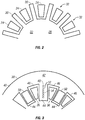
- FIG. 3 shown is an embodiment of a cooling scheme for the stator 14. It is to be appreciated that while the description herein is in the context of the stator core 38, it is merely exemplary and for illustrative purposes. The scheme disclosed herein may additionally or alternatively be applied to a rotor core 22.
- a single exemplary stator core lamination 40 of the stator core 38 is shown in FIG. 3 . It shall be understood that the stator core 38 can be formed of a plurality of stator core laminations 40.
- the stator core teeth 44 are arranged such that a first stator core tooth 44 has a coolant tube bank 48 extending axially therethrough and a second, adjacent stator core tooth 44 has a mixing chamber 50 extending axially therethrough. The arrangement of coolant tube banks 48 and mixing chambers 50 continues in alternating stator core teeth 44 around the stator core 38.
- the coolant tube bank 48 includes a plurality of cooling tubes 52, arranged, for example, along a substantially radially extending line 54. It is to be appreciated, however, that this arrangement is merely exemplary, and other arrangements of cooling tubes 52 in the stator core tooth 44 are contemplated in the present disclosure.
- a quantity of cooling tubes 52 in the coolant tube bank 48 may vary depending on, for example, stator core tooth 44 size and cooling desired.
- the coolant tube bank 48 may have between 3 and 15 cooling tubes 52, while in other embodiments, there are 13 cooling tubes 52 in the coolant tube bank 48.
- Multiple cooling tubes 52 provide redundancy and make the cooling path more tolerant of plugging of one or more cooling tubes 52.
- layers of coolant tube banks 48 and mixing chambers 50 alternate along an axial length 56 of the stator core 38.
- the layers have a thickness that is greater than the thickness of one stator core lamination 40.
- the stacked layers can be between 3 and 8 times the thickness of one stator core lamination 40, therefore including 3 to 8 stator core laminations 40, which in some embodiments are substantially identical, in an axial stack
- the axially alternating sequence of tube banks 48 and mixing chambers 50 is formed during assembly of the stator core 38 by rotating successive multi-lamination layers by one stator core tooth 44.
- the stacking arrangement determines heat transfer and pressure drop characteristics of the rotor 14 cooling scheme.
- a flow of coolant 62 is urged to the stator core 38 from a coolant source 58.
- a manifold 60 may be located between the coolant source 58 and the stator core 38 to distribute the coolant 62 to the plurality of stator core teeth 44.
- the manifold 60 is typically situated at an axial centerline of the stator core 58.
- the coolant 62 flows axially through the stator core tooth 44 alternatively through the axially staggered coolant tube banks 48 and mixing chambers 50.
- cooling tubes 52 in successive coolant tube banks 48 may be offset or staggered, for example, radially, to promote liquid mixing and disruption in the boundary layer, by defining a trip in the flow, which improves heat transfer between the stator core 38 and the coolant 62.
- a single lamination may consist of both mixing chambers 50 in some zones and cooling tubes 52. The clocking scheme will provide the alternation of those patterns in a given zone.
- the cooling scheme described herein may be used in combination with other cooling schemes, for example, end-turn spray cooling and back-iron cooling.
- the axial profile of temperature in the stator winding 36 is flattened, reducing the hot spot at the center axial area of the stator core 38 and average temperature is lowered compared to conventional cooling.
- the network of passages including the plurality coolant tube banks 48 and plurality of mixing chambers 50 provides both a high wetted surface area and excellent heat transfer coefficients due to their small size.
- the temperature rise is limited as it is inversely proportional to the area and the heat transfer coefficient.
- performance of the cooling system namely the trade between heat transfer and pressure drop, can be adjusted without changing the lamination design by simply changing the pattern of stacking the stator core laminations 40.
Landscapes
- Engineering & Computer Science (AREA)
- Power Engineering (AREA)
- Iron Core Of Rotating Electric Machines (AREA)
Claims (7)
- Noyau pour une machine électrique (10) comprenant :un composant de noyau (42) possédant une pluralité de dents de noyau (44) définissant une pluralité de fentes de noyau (46) entre des dents de noyau adjacentes (44) de la pluralité de dents de noyau (44), la pluralité de fentes de noyau (46) recevant un ou plusieurs enroulements (36) ; etun trajet d'écoulement de réfrigérant à travers le composant de noyau (42) formé à travers au moins une dent de noyau (44),caractérisé parl'au moins une dent de noyau (44) possédant trois rangées de tubes de réfrigérant (48) ou plus et deux chambres de mélange (50) ou plus agencées selon un modèle alternatif sur une longueur axiale de l'au moins une dent de noyau (44), une première chambre de mélange (50) recevant un flux de réfrigérant provenant de deux tubes de réfrigérant (52) ou plus d'une première rangée de tubes de réfrigérant (48) au niveau d'une première extrémité axiale de la première chambre de mélange (50) et distribuant le flux de réfrigérant à deux tubes de réfrigérant (52) ou plus d'une deuxième rangée de tubes de réfrigérant (48) au niveau d'une seconde extrémité axiale de la première chambre de mélange (50), tous les tubes de réfrigérant (52) de la première rangée de tubes de réfrigérant (48) étant radialement décalés par rapport à tous les tubes de réfrigérant (52) de la deuxième rangée de tubes de réfrigérant (48), une seconde chambre de mélange (50) recevant le flux de réfrigérant provenant de la deuxième rangée de tubes de réfrigérant (48) et distribuant le flux de réfrigérant à deux tubes de réfrigérant (52) ou plus d'une troisième rangée de tubes de réfrigérant (48), tous les tubes de réfrigérant (52) de la troisième rangée de tubes de réfrigérant (48) étant radialement alignés avec les tubes de réfrigérant (52) correspondants de la première rangée de tubes de réfrigérant (48), la première rangée de tubes de réfrigérant (48) et la deuxième rangée de tubes de réfrigérant (48) ayant des nombres égaux de tubes de réfrigérant (52) ;dans lequel le composant de noyau (42) est formé à partir d'une pluralité de stratifications de noyau (40) agencées dans une pile sensiblement axiale ;dans lequel une première dent de noyau (44) de la pluralité de dents de noyau (44) de chaque stratification (40) comporte une rangée de tubes de réfrigérant (48), et une seconde dent de noyau (44) adjacente comporte une chambre de mélange (50) ;dans lequel tous les tubes de réfrigérant de chaque nième rangée de tubes de réfrigérant sont radialement alignés avec des tubes de réfrigérant correspondants de la (n-2)ième rangée de tubes de réfrigérant ; et dans lequel toutes les rangées de tubes de réfrigérant (48) ont des nombres égaux de tubes de réfrigérant (52).
- Noyau selon la revendication 1, dans lequel chaque rangée de tubes de réfrigérant (48) comprend entre 3 et 15 tubes de réfrigérant.
- Noyau selon la revendication 1, dans lequel chaque rangée de tubes de réfrigérant (48) et chaque chambre de mélange (50) a une épaisseur d'au moins une stratification de noyau (40).
- Noyau selon la revendication 3, dans lequel les dents de noyau (44) restantes de la pluralité de dents de noyau (44) comportent alternativement une rangée de tubes de réfrigérant (48) ou une chambre de mélange (50).
- Noyau selon une quelconque revendication précédente, dans lequel le noyau est un noyau de stator.
- Noyau selon l'une quelconque des revendications 1 à 4, dans lequel le noyau est un noyau de rotor.
- Machine électrique (10) comprenant :un rotor (12) disposé au niveau d'un axe central de la machine électrique (10) ;un stator (14) entourant au moins partiellement le rotor (12) ; le stator (14) comportant :au moins un enroulement de stator (36) ;un noyau de stator (38) selon la revendication 5 possédant une pluralité de dents de noyau de stator (44) définissant une pluralité de fentes de noyau de stator (46) entre des dents de noyau de stator (44) adjacentes de la pluralité de dents de noyau de stator (44), la pluralité de fentes de noyau de stator (46) recevant l'au moins un enroulement de stator (36) ; etun trajet d'écoulement de réfrigérant à travers le noyau de stator (42) formé à travers au moins une dent de noyau de stator (44) de la pluralité de dents de noyau de stator (44) possédant trois rangées de tubes de réfrigérant (48) ou plus et deux chambres de mélange (50) ou plus agencées selon un modèle alternatif sur une longueur axiale de l'au moins une dent de noyau de stator (44), une première chambre de mélange (50) recevant un flux de réfrigérant liquide provenant de deux tubes de réfrigérant (52) ou plus d'une première rangée de tubes de réfrigérant (48) au niveau d'une première extrémité axiale de la première chambre de mélange (50) et distribuant le flux de réfrigérant à deux tubes de réfrigérant (52) ou plus d'une deuxième rangée de tubes de réfrigérant (48) au niveau d'une seconde extrémité axiale de la première chambre de mélange (50), tous les tubes de réfrigérant (52) de la première rangée de tubes de réfrigérant (48) étant radialement décalés par rapport à tous les tubes de réfrigérant (52) de la deuxième rangée de tubes de réfrigérant (48), une seconde chambre de mélange (50) recevant le flux de réfrigérant provenant de la deuxième rangée de tubes de réfrigérant (48) et distribuant le flux de réfrigérant à deux tubes de réfrigérant (52) ou plus d'une troisième rangée de tubes de réfrigérant (48), tous les tubes de réfrigérant de la troisième rangée de tubes de réfrigérant (48) étant radialement alignés avec les tubes de réfrigérant (52) correspondants de la première rangée de tubes de réfrigérant (48), la première rangée de tubes de réfrigérant (48) et la deuxième rangée de tubes de réfrigérant (48) ayant des nombres égaux de tubes de réfrigérant (52) ;dans lequel le trajet d'écoulement de réfrigérant permet un écoulement de réfrigérant liquide (62) à travers celui-ci pour refroidir le stator (14).
Applications Claiming Priority (1)
| Application Number | Priority Date | Filing Date | Title |
|---|---|---|---|
| US13/250,185 US9225208B2 (en) | 2011-09-30 | 2011-09-30 | Internal cooling of magnetic core for electric machine |
Publications (3)
| Publication Number | Publication Date |
|---|---|
| EP2575237A2 EP2575237A2 (fr) | 2013-04-03 |
| EP2575237A3 EP2575237A3 (fr) | 2017-06-14 |
| EP2575237B1 true EP2575237B1 (fr) | 2021-03-03 |
Family
ID=47010215
Family Applications (1)
| Application Number | Title | Priority Date | Filing Date |
|---|---|---|---|
| EP12181970.0A Active EP2575237B1 (fr) | 2011-09-30 | 2012-08-28 | Refroidissement interne du noyau magnétique pour machine électrique |
Country Status (2)
| Country | Link |
|---|---|
| US (1) | US9225208B2 (fr) |
| EP (1) | EP2575237B1 (fr) |
Cited By (2)
| Publication number | Priority date | Publication date | Assignee | Title |
|---|---|---|---|---|
| EP4096063A1 (fr) * | 2021-05-24 | 2022-11-30 | Hamilton Sundstrand Corporation | Refroidissement à deux phases pour machines électriques |
| WO2025059132A1 (fr) * | 2023-09-12 | 2025-03-20 | Vitesco Technologies USA, LLC | Canaux de refroidissement intégrés pour stators |
Families Citing this family (15)
| Publication number | Priority date | Publication date | Assignee | Title |
|---|---|---|---|---|
| JP6343092B2 (ja) | 2014-03-27 | 2018-06-13 | プリペル テクノロジーズ,リミティド ライアビリティ カンパニー | 横断液冷式回転子および固定子を有する誘導電動機 |
| CN104065186B (zh) * | 2014-06-13 | 2017-10-17 | 新疆金风科技股份有限公司 | 一种用于电机的定子、电机及其通风冷却方法 |
| US11255612B2 (en) | 2014-07-25 | 2022-02-22 | Enure, Inc. | Wound strip machine |
| CN106662408B (zh) | 2014-07-25 | 2019-11-05 | 普里派尔技术有限公司 | 流体冷却型卷绕式条带结构 |
| US10756583B2 (en) | 2014-07-25 | 2020-08-25 | Enure, Inc. | Wound strip machine |
| US20160111949A1 (en) | 2014-10-17 | 2016-04-21 | Hamilton Sundstrand Corporation | Dual frequency electrical generators |
| KR101972682B1 (ko) * | 2015-01-30 | 2019-04-25 | 프리펠 테크놀로지스, 엘엘씨 | 액체 냉각 이빨들을 구비하는 전기 기계 고정자 |
| GB2577820B (en) | 2017-06-02 | 2022-04-27 | Magnix Tech Pty Ltd | Cooling arrangements in devices or components with windings |
| DE102017211317A1 (de) * | 2017-07-04 | 2019-01-10 | Bayerische Motoren Werke Aktiengesellschaft | Stator einer elektrischen Maschine sowie Kühlvorrichtung hierfür |
| US11128201B2 (en) | 2017-09-06 | 2021-09-21 | Ge Aviation Systems Llc | Method and assembly of a stator sleeve |
| US10707716B2 (en) | 2017-11-20 | 2020-07-07 | Borgwarner Inc. | Stator core and stator slot closer |
| US10964469B2 (en) * | 2018-04-30 | 2021-03-30 | Toyota Motor Engineering & Manufacturing North America, Inc. | Cooling magnetic cores with ferrofluid and magnetic cores so cooled |
| CN109802524A (zh) * | 2019-03-21 | 2019-05-24 | 哈尔滨理工大学 | 一种具有新型冷却结构的绕线式无刷双馈电机 |
| US11794913B2 (en) | 2020-10-20 | 2023-10-24 | The Boeing Company | Integrated electric propulsion unit |
| US20250293563A1 (en) * | 2024-03-12 | 2025-09-18 | General Electric Deutschland Holding Gmbh | Electric machine with cooling features |
Family Cites Families (14)
| Publication number | Priority date | Publication date | Assignee | Title |
|---|---|---|---|---|
| US890577A (en) * | 1906-10-31 | 1908-06-09 | Allis Chalmers | Ventilated laminated core for dynamo-electric machines. |
| US3116429A (en) * | 1962-04-02 | 1963-12-31 | Gen Electric | Cooling arrangement for the stator teeth of a dynamoelectric machine |
| US4352034A (en) * | 1980-12-22 | 1982-09-28 | General Electric Company | Stator core with axial and radial cooling for dynamoelectric machines wth air-gap stator windings |
| JPS5956832A (ja) * | 1982-09-25 | 1984-04-02 | Fuji Electric Co Ltd | 電気機器の鉄心 |
| DE3444189A1 (de) * | 1984-03-21 | 1985-09-26 | Kraftwerk Union AG, 4330 Mülheim | Einrichtung zur indirekten gaskuehlung der staenderwicklung und/oder zur direkten gaskuehlung des staenderblechpaketes dynamoelektrischer maschinen, vorzugsweise fuer gasgekuehlte turbogeneratoren |
| JPS63144734A (ja) * | 1986-12-08 | 1988-06-16 | Fuji Electric Co Ltd | 回転電機の回転子導体 |
| GB2289992B (en) * | 1994-05-24 | 1998-05-20 | Gec Alsthom Ltd | Improvements in or relating to cooling arrangements in rotating electrical machines |
| US5703421A (en) * | 1996-05-24 | 1997-12-30 | The United States Of America As Represented By The Secretary Of The Air Force | Reluctance generator/motor cooling |
| DE19939598A1 (de) * | 1999-08-20 | 2001-03-08 | Magnet Motor Gmbh | Reluktanz-Elektromaschine |
| US6504274B2 (en) * | 2001-01-04 | 2003-01-07 | General Electric Company | Generator stator cooling design with concavity surfaces |
| JP3596514B2 (ja) * | 2001-11-08 | 2004-12-02 | 日産自動車株式会社 | 回転電機の冷却構造 |
| WO2003094323A1 (fr) * | 2002-05-06 | 2003-11-13 | Aerovironment, Inc. | Systeme de refroidissement de toles |
| JP5221902B2 (ja) * | 2007-06-12 | 2013-06-26 | 株式会社小松製作所 | モータ |
| US20100102649A1 (en) * | 2008-10-24 | 2010-04-29 | Deere & Company | Hydroformed cooling channels in stator laminations |
-
2011
- 2011-09-30 US US13/250,185 patent/US9225208B2/en active Active
-
2012
- 2012-08-28 EP EP12181970.0A patent/EP2575237B1/fr active Active
Non-Patent Citations (1)
| Title |
|---|
| None * |
Cited By (2)
| Publication number | Priority date | Publication date | Assignee | Title |
|---|---|---|---|---|
| EP4096063A1 (fr) * | 2021-05-24 | 2022-11-30 | Hamilton Sundstrand Corporation | Refroidissement à deux phases pour machines électriques |
| WO2025059132A1 (fr) * | 2023-09-12 | 2025-03-20 | Vitesco Technologies USA, LLC | Canaux de refroidissement intégrés pour stators |
Also Published As
| Publication number | Publication date |
|---|---|
| US20130113311A1 (en) | 2013-05-09 |
| EP2575237A2 (fr) | 2013-04-03 |
| EP2575237A3 (fr) | 2017-06-14 |
| US9225208B2 (en) | 2015-12-29 |
Similar Documents
| Publication | Publication Date | Title |
|---|---|---|
| EP2575237B1 (fr) | Refroidissement interne du noyau magnétique pour machine électrique | |
| CN109155558B (zh) | 电机以及具有该电机的车辆 | |
| JP6302736B2 (ja) | 回転電機 | |
| US11355976B2 (en) | Integral fluid cooling of electrical machine | |
| EP2058926B1 (fr) | Système de refroidissement de moteur amélioré | |
| EP2568574B1 (fr) | Machine électrique tournante triphasée et son procédé de fabrication | |
| EP1557929B1 (fr) | Procédé et appareil permettant la réduction de la température des points chauds des bobines exitatrices empilés | |
| JP2020120470A (ja) | 回転電機 | |
| CN116317242B (zh) | 一种油冷电机 | |
| JP2018504881A (ja) | 流体冷却ティースを備えた電気機械ステータ | |
| WO2016044570A1 (fr) | Appareil de refroidissement de spire d'extrémité de machine électrique | |
| US20240146134A1 (en) | Stator of an electric flux machine, and axial flux machine | |
| US20140361649A1 (en) | Cooling arrangement for an electrical machine | |
| US20220200367A1 (en) | Stator for electrical machines | |
| JP2023181995A (ja) | ロータ用の変位体及びそれにより形成されたロータ | |
| WO2013112067A1 (fr) | Machine dynamo-électrique dotée d'une ventilation de rotor améliorée | |
| CN117999728A (zh) | 电机 | |
| KR20170086903A (ko) | 모터 장치 및 그 고정자 코어 | |
| DK2313959T3 (en) | Rotor for a multi-pole synchronous electric motor with protruding poles | |
| JP7250214B2 (ja) | 固定子および回転電機 | |
| WO2025099993A1 (fr) | Stator de machine électrique tournante | |
| EP3312974B1 (fr) | Système de refroidissement à jet d'écoulement à contre-courant radial | |
| JP5330860B2 (ja) | 回転電機 | |
| US12489327B2 (en) | Cooled rotor of an electric machine | |
| CN112713674B (zh) | 电动机的定子 |
Legal Events
| Date | Code | Title | Description |
|---|---|---|---|
| PUAI | Public reference made under article 153(3) epc to a published international application that has entered the european phase |
Free format text: ORIGINAL CODE: 0009012 |
|
| AK | Designated contracting states |
Kind code of ref document: A2 Designated state(s): AL AT BE BG CH CY CZ DE DK EE ES FI FR GB GR HR HU IE IS IT LI LT LU LV MC MK MT NL NO PL PT RO RS SE SI SK SM TR |
|
| AX | Request for extension of the european patent |
Extension state: BA ME |
|
| PUAL | Search report despatched |
Free format text: ORIGINAL CODE: 0009013 |
|
| AK | Designated contracting states |
Kind code of ref document: A3 Designated state(s): AL AT BE BG CH CY CZ DE DK EE ES FI FR GB GR HR HU IE IS IT LI LT LU LV MC MK MT NL NO PL PT RO RS SE SI SK SM TR |
|
| AX | Request for extension of the european patent |
Extension state: BA ME |
|
| RIC1 | Information provided on ipc code assigned before grant |
Ipc: H02K 1/20 20060101AFI20170511BHEP |
|
| STAA | Information on the status of an ep patent application or granted ep patent |
Free format text: STATUS: REQUEST FOR EXAMINATION WAS MADE |
|
| 17P | Request for examination filed |
Effective date: 20171214 |
|
| RBV | Designated contracting states (corrected) |
Designated state(s): AL AT BE BG CH CY CZ DE DK EE ES FI FR GB GR HR HU IE IS IT LI LT LU LV MC MK MT NL NO PL PT RO RS SE SI SK SM TR |
|
| STAA | Information on the status of an ep patent application or granted ep patent |
Free format text: STATUS: EXAMINATION IS IN PROGRESS |
|
| 17Q | First examination report despatched |
Effective date: 20200417 |
|
| GRAP | Despatch of communication of intention to grant a patent |
Free format text: ORIGINAL CODE: EPIDOSNIGR1 |
|
| STAA | Information on the status of an ep patent application or granted ep patent |
Free format text: STATUS: GRANT OF PATENT IS INTENDED |
|
| INTG | Intention to grant announced |
Effective date: 20200922 |
|
| RIN1 | Information on inventor provided before grant (corrected) |
Inventor name: COLLINGS, ROGER JOHN Inventor name: NAYAK, HEBRI VIJAYENDRA Inventor name: CAMPBELL, KRIS H. Inventor name: FRANZEN, MARK F. Inventor name: DOWNING, ROBERT SCOTT |
|
| RAP1 | Party data changed (applicant data changed or rights of an application transferred) |
Owner name: HAMILTON SUNDSTRAND CORPORATION |
|
| GRAS | Grant fee paid |
Free format text: ORIGINAL CODE: EPIDOSNIGR3 |
|
| GRAA | (expected) grant |
Free format text: ORIGINAL CODE: 0009210 |
|
| STAA | Information on the status of an ep patent application or granted ep patent |
Free format text: STATUS: THE PATENT HAS BEEN GRANTED |
|
| AK | Designated contracting states |
Kind code of ref document: B1 Designated state(s): AL AT BE BG CH CY CZ DE DK EE ES FI FR GB GR HR HU IE IS IT LI LT LU LV MC MK MT NL NO PL PT RO RS SE SI SK SM TR |
|
| REG | Reference to a national code |
Ref country code: GB Ref legal event code: FG4D |
|
| REG | Reference to a national code |
Ref country code: AT Ref legal event code: REF Ref document number: 1368291 Country of ref document: AT Kind code of ref document: T Effective date: 20210315 Ref country code: CH Ref legal event code: EP |
|
| REG | Reference to a national code |
Ref country code: DE Ref legal event code: R096 Ref document number: 602012074591 Country of ref document: DE |
|
| REG | Reference to a national code |
Ref country code: IE Ref legal event code: FG4D |
|
| REG | Reference to a national code |
Ref country code: LT Ref legal event code: MG9D |
|
| PG25 | Lapsed in a contracting state [announced via postgrant information from national office to epo] |
Ref country code: LT Free format text: LAPSE BECAUSE OF FAILURE TO SUBMIT A TRANSLATION OF THE DESCRIPTION OR TO PAY THE FEE WITHIN THE PRESCRIBED TIME-LIMIT Effective date: 20210303 Ref country code: HR Free format text: LAPSE BECAUSE OF FAILURE TO SUBMIT A TRANSLATION OF THE DESCRIPTION OR TO PAY THE FEE WITHIN THE PRESCRIBED TIME-LIMIT Effective date: 20210303 Ref country code: FI Free format text: LAPSE BECAUSE OF FAILURE TO SUBMIT A TRANSLATION OF THE DESCRIPTION OR TO PAY THE FEE WITHIN THE PRESCRIBED TIME-LIMIT Effective date: 20210303 Ref country code: GR Free format text: LAPSE BECAUSE OF FAILURE TO SUBMIT A TRANSLATION OF THE DESCRIPTION OR TO PAY THE FEE WITHIN THE PRESCRIBED TIME-LIMIT Effective date: 20210604 Ref country code: BG Free format text: LAPSE BECAUSE OF FAILURE TO SUBMIT A TRANSLATION OF THE DESCRIPTION OR TO PAY THE FEE WITHIN THE PRESCRIBED TIME-LIMIT Effective date: 20210603 Ref country code: NO Free format text: LAPSE BECAUSE OF FAILURE TO SUBMIT A TRANSLATION OF THE DESCRIPTION OR TO PAY THE FEE WITHIN THE PRESCRIBED TIME-LIMIT Effective date: 20210603 |
|
| REG | Reference to a national code |
Ref country code: NL Ref legal event code: MP Effective date: 20210303 |
|
| REG | Reference to a national code |
Ref country code: AT Ref legal event code: MK05 Ref document number: 1368291 Country of ref document: AT Kind code of ref document: T Effective date: 20210303 |
|
| PG25 | Lapsed in a contracting state [announced via postgrant information from national office to epo] |
Ref country code: SE Free format text: LAPSE BECAUSE OF FAILURE TO SUBMIT A TRANSLATION OF THE DESCRIPTION OR TO PAY THE FEE WITHIN THE PRESCRIBED TIME-LIMIT Effective date: 20210303 Ref country code: LV Free format text: LAPSE BECAUSE OF FAILURE TO SUBMIT A TRANSLATION OF THE DESCRIPTION OR TO PAY THE FEE WITHIN THE PRESCRIBED TIME-LIMIT Effective date: 20210303 Ref country code: RS Free format text: LAPSE BECAUSE OF FAILURE TO SUBMIT A TRANSLATION OF THE DESCRIPTION OR TO PAY THE FEE WITHIN THE PRESCRIBED TIME-LIMIT Effective date: 20210303 Ref country code: PL Free format text: LAPSE BECAUSE OF FAILURE TO SUBMIT A TRANSLATION OF THE DESCRIPTION OR TO PAY THE FEE WITHIN THE PRESCRIBED TIME-LIMIT Effective date: 20210303 |
|
| PG25 | Lapsed in a contracting state [announced via postgrant information from national office to epo] |
Ref country code: NL Free format text: LAPSE BECAUSE OF FAILURE TO SUBMIT A TRANSLATION OF THE DESCRIPTION OR TO PAY THE FEE WITHIN THE PRESCRIBED TIME-LIMIT Effective date: 20210303 |
|
| PG25 | Lapsed in a contracting state [announced via postgrant information from national office to epo] |
Ref country code: AT Free format text: LAPSE BECAUSE OF FAILURE TO SUBMIT A TRANSLATION OF THE DESCRIPTION OR TO PAY THE FEE WITHIN THE PRESCRIBED TIME-LIMIT Effective date: 20210303 Ref country code: SM Free format text: LAPSE BECAUSE OF FAILURE TO SUBMIT A TRANSLATION OF THE DESCRIPTION OR TO PAY THE FEE WITHIN THE PRESCRIBED TIME-LIMIT Effective date: 20210303 Ref country code: CZ Free format text: LAPSE BECAUSE OF FAILURE TO SUBMIT A TRANSLATION OF THE DESCRIPTION OR TO PAY THE FEE WITHIN THE PRESCRIBED TIME-LIMIT Effective date: 20210303 Ref country code: EE Free format text: LAPSE BECAUSE OF FAILURE TO SUBMIT A TRANSLATION OF THE DESCRIPTION OR TO PAY THE FEE WITHIN THE PRESCRIBED TIME-LIMIT Effective date: 20210303 |
|
| PG25 | Lapsed in a contracting state [announced via postgrant information from national office to epo] |
Ref country code: ES Free format text: LAPSE BECAUSE OF FAILURE TO SUBMIT A TRANSLATION OF THE DESCRIPTION OR TO PAY THE FEE WITHIN THE PRESCRIBED TIME-LIMIT Effective date: 20210303 Ref country code: PT Free format text: LAPSE BECAUSE OF FAILURE TO SUBMIT A TRANSLATION OF THE DESCRIPTION OR TO PAY THE FEE WITHIN THE PRESCRIBED TIME-LIMIT Effective date: 20210705 Ref country code: SK Free format text: LAPSE BECAUSE OF FAILURE TO SUBMIT A TRANSLATION OF THE DESCRIPTION OR TO PAY THE FEE WITHIN THE PRESCRIBED TIME-LIMIT Effective date: 20210303 Ref country code: IS Free format text: LAPSE BECAUSE OF FAILURE TO SUBMIT A TRANSLATION OF THE DESCRIPTION OR TO PAY THE FEE WITHIN THE PRESCRIBED TIME-LIMIT Effective date: 20210703 Ref country code: RO Free format text: LAPSE BECAUSE OF FAILURE TO SUBMIT A TRANSLATION OF THE DESCRIPTION OR TO PAY THE FEE WITHIN THE PRESCRIBED TIME-LIMIT Effective date: 20210303 |
|
| REG | Reference to a national code |
Ref country code: DE Ref legal event code: R097 Ref document number: 602012074591 Country of ref document: DE |
|
| PLBE | No opposition filed within time limit |
Free format text: ORIGINAL CODE: 0009261 |
|
| STAA | Information on the status of an ep patent application or granted ep patent |
Free format text: STATUS: NO OPPOSITION FILED WITHIN TIME LIMIT |
|
| PG25 | Lapsed in a contracting state [announced via postgrant information from national office to epo] |
Ref country code: DK Free format text: LAPSE BECAUSE OF FAILURE TO SUBMIT A TRANSLATION OF THE DESCRIPTION OR TO PAY THE FEE WITHIN THE PRESCRIBED TIME-LIMIT Effective date: 20210303 Ref country code: AL Free format text: LAPSE BECAUSE OF FAILURE TO SUBMIT A TRANSLATION OF THE DESCRIPTION OR TO PAY THE FEE WITHIN THE PRESCRIBED TIME-LIMIT Effective date: 20210303 |
|
| 26N | No opposition filed |
Effective date: 20211206 |
|
| PG25 | Lapsed in a contracting state [announced via postgrant information from national office to epo] |
Ref country code: SI Free format text: LAPSE BECAUSE OF FAILURE TO SUBMIT A TRANSLATION OF THE DESCRIPTION OR TO PAY THE FEE WITHIN THE PRESCRIBED TIME-LIMIT Effective date: 20210303 |
|
| REG | Reference to a national code |
Ref country code: CH Ref legal event code: PL |
|
| PG25 | Lapsed in a contracting state [announced via postgrant information from national office to epo] |
Ref country code: MC Free format text: LAPSE BECAUSE OF FAILURE TO SUBMIT A TRANSLATION OF THE DESCRIPTION OR TO PAY THE FEE WITHIN THE PRESCRIBED TIME-LIMIT Effective date: 20210303 |
|
| REG | Reference to a national code |
Ref country code: BE Ref legal event code: MM Effective date: 20210831 |
|
| PG25 | Lapsed in a contracting state [announced via postgrant information from national office to epo] |
Ref country code: LI Free format text: LAPSE BECAUSE OF NON-PAYMENT OF DUE FEES Effective date: 20210831 Ref country code: IT Free format text: LAPSE BECAUSE OF FAILURE TO SUBMIT A TRANSLATION OF THE DESCRIPTION OR TO PAY THE FEE WITHIN THE PRESCRIBED TIME-LIMIT Effective date: 20210303 Ref country code: CH Free format text: LAPSE BECAUSE OF NON-PAYMENT OF DUE FEES Effective date: 20210831 |
|
| PG25 | Lapsed in a contracting state [announced via postgrant information from national office to epo] |
Ref country code: IS Free format text: LAPSE BECAUSE OF FAILURE TO SUBMIT A TRANSLATION OF THE DESCRIPTION OR TO PAY THE FEE WITHIN THE PRESCRIBED TIME-LIMIT Effective date: 20210703 Ref country code: LU Free format text: LAPSE BECAUSE OF NON-PAYMENT OF DUE FEES Effective date: 20210828 |
|
| PG25 | Lapsed in a contracting state [announced via postgrant information from national office to epo] |
Ref country code: IE Free format text: LAPSE BECAUSE OF NON-PAYMENT OF DUE FEES Effective date: 20210828 Ref country code: BE Free format text: LAPSE BECAUSE OF NON-PAYMENT OF DUE FEES Effective date: 20210831 |
|
| PG25 | Lapsed in a contracting state [announced via postgrant information from national office to epo] |
Ref country code: HU Free format text: LAPSE BECAUSE OF FAILURE TO SUBMIT A TRANSLATION OF THE DESCRIPTION OR TO PAY THE FEE WITHIN THE PRESCRIBED TIME-LIMIT; INVALID AB INITIO Effective date: 20120828 Ref country code: CY Free format text: LAPSE BECAUSE OF FAILURE TO SUBMIT A TRANSLATION OF THE DESCRIPTION OR TO PAY THE FEE WITHIN THE PRESCRIBED TIME-LIMIT Effective date: 20210303 |
|
| P01 | Opt-out of the competence of the unified patent court (upc) registered |
Effective date: 20230522 |
|
| PG25 | Lapsed in a contracting state [announced via postgrant information from national office to epo] |
Ref country code: MK Free format text: LAPSE BECAUSE OF FAILURE TO SUBMIT A TRANSLATION OF THE DESCRIPTION OR TO PAY THE FEE WITHIN THE PRESCRIBED TIME-LIMIT Effective date: 20210303 |
|
| PG25 | Lapsed in a contracting state [announced via postgrant information from national office to epo] |
Ref country code: TR Free format text: LAPSE BECAUSE OF FAILURE TO SUBMIT A TRANSLATION OF THE DESCRIPTION OR TO PAY THE FEE WITHIN THE PRESCRIBED TIME-LIMIT Effective date: 20210303 |
|
| PG25 | Lapsed in a contracting state [announced via postgrant information from national office to epo] |
Ref country code: MT Free format text: LAPSE BECAUSE OF FAILURE TO SUBMIT A TRANSLATION OF THE DESCRIPTION OR TO PAY THE FEE WITHIN THE PRESCRIBED TIME-LIMIT Effective date: 20210303 |
|
| PGFP | Annual fee paid to national office [announced via postgrant information from national office to epo] |
Ref country code: DE Payment date: 20250724 Year of fee payment: 14 |
|
| PGFP | Annual fee paid to national office [announced via postgrant information from national office to epo] |
Ref country code: GB Payment date: 20250724 Year of fee payment: 14 |
|
| PGFP | Annual fee paid to national office [announced via postgrant information from national office to epo] |
Ref country code: FR Payment date: 20250723 Year of fee payment: 14 |