EP2575237B1 - Internal cooling of magnetic core for electric machine - Google Patents
Internal cooling of magnetic core for electric machine Download PDFInfo
- Publication number
- EP2575237B1 EP2575237B1 EP12181970.0A EP12181970A EP2575237B1 EP 2575237 B1 EP2575237 B1 EP 2575237B1 EP 12181970 A EP12181970 A EP 12181970A EP 2575237 B1 EP2575237 B1 EP 2575237B1
- Authority
- EP
- European Patent Office
- Prior art keywords
- coolant
- core
- tube bank
- tubes
- stator
- Prior art date
- Legal status (The legal status is an assumption and is not a legal conclusion. Google has not performed a legal analysis and makes no representation as to the accuracy of the status listed.)
- Active
Links
Images


Classifications
-
- H—ELECTRICITY
- H02—GENERATION; CONVERSION OR DISTRIBUTION OF ELECTRIC POWER
- H02K—DYNAMO-ELECTRIC MACHINES
- H02K1/00—Details of the magnetic circuit
- H02K1/06—Details of the magnetic circuit characterised by the shape, form or construction
- H02K1/12—Stationary parts of the magnetic circuit
- H02K1/20—Stationary parts of the magnetic circuit with channels or ducts for flow of cooling medium
-
- H—ELECTRICITY
- H02—GENERATION; CONVERSION OR DISTRIBUTION OF ELECTRIC POWER
- H02K—DYNAMO-ELECTRIC MACHINES
- H02K1/00—Details of the magnetic circuit
- H02K1/06—Details of the magnetic circuit characterised by the shape, form or construction
- H02K1/22—Rotating parts of the magnetic circuit
- H02K1/32—Rotating parts of the magnetic circuit with channels or ducts for flow of cooling medium
-
- H—ELECTRICITY
- H02—GENERATION; CONVERSION OR DISTRIBUTION OF ELECTRIC POWER
- H02K—DYNAMO-ELECTRIC MACHINES
- H02K9/00—Arrangements for cooling or ventilating
- H02K9/19—Arrangements for cooling or ventilating for machines with closed casing and closed-circuit cooling using a liquid cooling medium, e.g. oil
- H02K9/197—Arrangements for cooling or ventilating for machines with closed casing and closed-circuit cooling using a liquid cooling medium, e.g. oil in which the rotor or stator space is fluid-tight, e.g. to provide for different cooling media for rotor and stator
Definitions
- the subject matter disclosed herein relates to electrical machines. More specifically, the subject matter disclosed herein relates to liquid cooling of magnetic cores of electric machines.
- a typical liquid cooled electric machine includes a rotor having a core and one or more rotor windings (conductors) extending therethrough.
- the rotor windings are replaced with a plurality of permanent magnets.
- the rotor is surrounded by a stator and an air gap exists between the rotor and stator.
- the stator includes a stator core having one or more stator windings extending therethrough.
- High power density electric machines either generator or motor
- Typical methods of stator cooling include utilizing an end-turn spray and thermal conduction through the back iron to a cooled housing or fluid media.
- the end turn spray is most often from orifices in the rotor, but it can be supplemented with fixed spray nozzles on the housing.
- the spray is directed at end turns of the stator windings to cool by impingement.
- Back iron cooling includes directing cooling liquid through one or more channels in the back iron (housing) radially outboard of the stator core.
- Cooling of wound rotors at low power densities is typically achieved by an oil flow in the rotor shaft and accompanying end turn spray from orifices in the rotor. Cooling of rotors at high power densities is achieved by an oil flow in the rotor shaft and axial flow within the rotor windings.
- US3116429 A discloses a core for an electrical machine according to the preamble of claim 1.
- FIG. 1 Shown in FIG. 1 is an embodiment of an electric machine 10, for example, a generator.
- the electric machine 10 includes a rotor 12 and a stator 14 surrounding at least a portion of the rotor 12 such that an air gap 16 exists between the rotor 12 and the stator 14.
- the rotor 12 is located on a central shaft 18 that rotates about a shaft axis 20 and is secured thereto such that the rotor 12 rotates about the shaft axis 20 with the shaft 18.
- the rotor 12 includes a magnetic rotor core 22 with one or more rotor windings 24 having a plurality of rotor conductors located at the rotor core 22.
- the rotor core 22 is formed of a plurality of rotor core laminations 26, which in some embodiments are stacked substantially axially to form the rotor core 22.
- the rotor core 22 includes a rotor core yoke 28 as a core component with a plurality of rotor core teeth 30 extending outwardly from the rotor core yoke 28 and arranged around a circumference thereof.
- a plurality of rotor core slots 32 are defined by adjacent rotor core teeth 30.
- the rotor windings 24 at least partially fill the rotor core slots 32.
- the stator 14 is located radially outboard of the rotor 12, and is adjacent to, or secured to a housing 34.
- the stator 14 includes one or more stator windings 36 having a plurality of stator conductors located at a magnetic stator core 38, which is formed of a plurality of stator core laminations 40, which in some embodiments may be stacked substantially axially.
- the stator core 38 includes a stator core yoke 42 as a core component with a plurality of stator core teeth 44 extending inwardly from the stator core yoke 42 and arranged around a circumference thereof.
- a plurality of stator core slots 46 are defined by adjacent stator core teeth 44.
- the stator windings 36 at least partially fill the stator core slots 46.
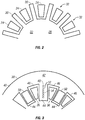
- FIG. 3 shown is an embodiment of a cooling scheme for the stator 14. It is to be appreciated that while the description herein is in the context of the stator core 38, it is merely exemplary and for illustrative purposes. The scheme disclosed herein may additionally or alternatively be applied to a rotor core 22.
- a single exemplary stator core lamination 40 of the stator core 38 is shown in FIG. 3 . It shall be understood that the stator core 38 can be formed of a plurality of stator core laminations 40.
- the stator core teeth 44 are arranged such that a first stator core tooth 44 has a coolant tube bank 48 extending axially therethrough and a second, adjacent stator core tooth 44 has a mixing chamber 50 extending axially therethrough. The arrangement of coolant tube banks 48 and mixing chambers 50 continues in alternating stator core teeth 44 around the stator core 38.
- the coolant tube bank 48 includes a plurality of cooling tubes 52, arranged, for example, along a substantially radially extending line 54. It is to be appreciated, however, that this arrangement is merely exemplary, and other arrangements of cooling tubes 52 in the stator core tooth 44 are contemplated in the present disclosure.
- a quantity of cooling tubes 52 in the coolant tube bank 48 may vary depending on, for example, stator core tooth 44 size and cooling desired.
- the coolant tube bank 48 may have between 3 and 15 cooling tubes 52, while in other embodiments, there are 13 cooling tubes 52 in the coolant tube bank 48.
- Multiple cooling tubes 52 provide redundancy and make the cooling path more tolerant of plugging of one or more cooling tubes 52.
- layers of coolant tube banks 48 and mixing chambers 50 alternate along an axial length 56 of the stator core 38.
- the layers have a thickness that is greater than the thickness of one stator core lamination 40.
- the stacked layers can be between 3 and 8 times the thickness of one stator core lamination 40, therefore including 3 to 8 stator core laminations 40, which in some embodiments are substantially identical, in an axial stack
- the axially alternating sequence of tube banks 48 and mixing chambers 50 is formed during assembly of the stator core 38 by rotating successive multi-lamination layers by one stator core tooth 44.
- the stacking arrangement determines heat transfer and pressure drop characteristics of the rotor 14 cooling scheme.
- a flow of coolant 62 is urged to the stator core 38 from a coolant source 58.
- a manifold 60 may be located between the coolant source 58 and the stator core 38 to distribute the coolant 62 to the plurality of stator core teeth 44.
- the manifold 60 is typically situated at an axial centerline of the stator core 58.
- the coolant 62 flows axially through the stator core tooth 44 alternatively through the axially staggered coolant tube banks 48 and mixing chambers 50.
- cooling tubes 52 in successive coolant tube banks 48 may be offset or staggered, for example, radially, to promote liquid mixing and disruption in the boundary layer, by defining a trip in the flow, which improves heat transfer between the stator core 38 and the coolant 62.
- a single lamination may consist of both mixing chambers 50 in some zones and cooling tubes 52. The clocking scheme will provide the alternation of those patterns in a given zone.
- the cooling scheme described herein may be used in combination with other cooling schemes, for example, end-turn spray cooling and back-iron cooling.
- the axial profile of temperature in the stator winding 36 is flattened, reducing the hot spot at the center axial area of the stator core 38 and average temperature is lowered compared to conventional cooling.
- the network of passages including the plurality coolant tube banks 48 and plurality of mixing chambers 50 provides both a high wetted surface area and excellent heat transfer coefficients due to their small size.
- the temperature rise is limited as it is inversely proportional to the area and the heat transfer coefficient.
- performance of the cooling system namely the trade between heat transfer and pressure drop, can be adjusted without changing the lamination design by simply changing the pattern of stacking the stator core laminations 40.
Landscapes
- Engineering & Computer Science (AREA)
- Power Engineering (AREA)
- Iron Core Of Rotating Electric Machines (AREA)
Description
- The subject matter disclosed herein relates to electrical machines. More specifically, the subject matter disclosed herein relates to liquid cooling of magnetic cores of electric machines.
- A typical liquid cooled electric machine includes a rotor having a core and one or more rotor windings (conductors) extending therethrough. In some machines, permanent magnet machines, the rotor windings are replaced with a plurality of permanent magnets. The rotor is surrounded by a stator and an air gap exists between the rotor and stator. Similarly, the stator includes a stator core having one or more stator windings extending therethrough. High power density electric machines (either generator or motor) produce intense resistive heating of both the stator and rotor windings and eddy current and magnetic hysteresis heating of the rotor and stator cores. Typical methods of stator cooling include utilizing an end-turn spray and thermal conduction through the back iron to a cooled housing or fluid media. The end turn spray is most often from orifices in the rotor, but it can be supplemented with fixed spray nozzles on the housing. The spray is directed at end turns of the stator windings to cool by impingement. Back iron cooling includes directing cooling liquid through one or more channels in the back iron (housing) radially outboard of the stator core. These cooling methods, however, provide cooling only on the radial and axial periphery of the stator core. Therefore, a hot spot in the stator windings can occur at the axial centerline of the stator core. With physically larger machines the conduction distances from the axial center position of the slots and teeth of the stator core becomes greater, limiting the power level of the machine or requiring lower temperature coolants.
- Cooling of wound rotors at low power densities is typically achieved by an oil flow in the rotor shaft and accompanying end turn spray from orifices in the rotor. Cooling of rotors at high power densities is achieved by an oil flow in the rotor shaft and axial flow within the rotor windings.
-
US3116429 A discloses a core for an electrical machine according to the preamble of claim 1. - According to a first aspect of the invention, there is provided a core for an electric machine as claimed in claim 1.
- According to a second aspect of the invention, there is provided an electric machine as claimed in claim 7. These and other advantages and features will become more apparent from the following description taken in conjunction with the drawings.
- The subject matter, which is regarded as the invention, is particularly pointed out and distinctly claimed in the claims at the conclusion of the specification. The foregoing and other features and advantages of the invention are apparent from the following detailed description taken in conjunction with the accompanying drawings in which:
-
FIG. 1 is a cross-sectional view of an embodiment of an electric machine showing a rotor and a partial view of a stator; -
FIG. 2 is an end view of an embodiment of a rotor for an electric machine; -
FIG. 3 is an end view of an embodiment of a stator for an electric machine; and -
FIG. 4 is a cross-sectional view of an embodiment of a stator for an electric machine. - The detailed description explains embodiments of the invention, together with advantages and features, by way of example with reference to the drawings.
- Shown in
FIG. 1 is an embodiment of anelectric machine 10, for example, a generator. Theelectric machine 10 includes arotor 12 and astator 14 surrounding at least a portion of therotor 12 such that anair gap 16 exists between therotor 12 and thestator 14. Therotor 12 is located on acentral shaft 18 that rotates about ashaft axis 20 and is secured thereto such that therotor 12 rotates about theshaft axis 20 with theshaft 18. Therotor 12 includes amagnetic rotor core 22 with one ormore rotor windings 24 having a plurality of rotor conductors located at therotor core 22. Therotor core 22 is formed of a plurality ofrotor core laminations 26, which in some embodiments are stacked substantially axially to form therotor core 22. Referring toFIG. 2 , therotor core 22 includes arotor core yoke 28 as a core component with a plurality ofrotor core teeth 30 extending outwardly from therotor core yoke 28 and arranged around a circumference thereof. A plurality ofrotor core slots 32 are defined by adjacentrotor core teeth 30. Therotor windings 24 at least partially fill therotor core slots 32. - Referring again to
FIG. 1 , thestator 14 is located radially outboard of therotor 12, and is adjacent to, or secured to ahousing 34. Thestator 14 includes one ormore stator windings 36 having a plurality of stator conductors located at amagnetic stator core 38, which is formed of a plurality ofstator core laminations 40, which in some embodiments may be stacked substantially axially. Referring toFIG. 3 , thestator core 38 includes astator core yoke 42 as a core component with a plurality ofstator core teeth 44 extending inwardly from thestator core yoke 42 and arranged around a circumference thereof. A plurality ofstator core slots 46 are defined by adjacentstator core teeth 44. Thestator windings 36 at least partially fill thestator core slots 46. - Referring still to
FIG. 3 , shown is an embodiment of a cooling scheme for thestator 14. It is to be appreciated that while the description herein is in the context of thestator core 38, it is merely exemplary and for illustrative purposes. The scheme disclosed herein may additionally or alternatively be applied to arotor core 22. A single exemplarystator core lamination 40 of thestator core 38 is shown inFIG. 3 . It shall be understood that thestator core 38 can be formed of a plurality ofstator core laminations 40. Thestator core teeth 44 are arranged such that a firststator core tooth 44 has acoolant tube bank 48 extending axially therethrough and a second, adjacentstator core tooth 44 has amixing chamber 50 extending axially therethrough. The arrangement ofcoolant tube banks 48 andmixing chambers 50 continues in alternatingstator core teeth 44 around thestator core 38. - The
coolant tube bank 48 includes a plurality ofcooling tubes 52, arranged, for example, along a substantially radially extendingline 54. It is to be appreciated, however, that this arrangement is merely exemplary, and other arrangements ofcooling tubes 52 in thestator core tooth 44 are contemplated in the present disclosure. A quantity ofcooling tubes 52 in thecoolant tube bank 48 may vary depending on, for example,stator core tooth 44 size and cooling desired. For example, in some embodiments, thecoolant tube bank 48 may have between 3 and 15cooling tubes 52, while in other embodiments, there are 13cooling tubes 52 in thecoolant tube bank 48.Multiple cooling tubes 52 provide redundancy and make the cooling path more tolerant of plugging of one ormore cooling tubes 52. - Referring now to
FIG. 4 , layers ofcoolant tube banks 48 andmixing chambers 50 alternate along anaxial length 56 of thestator core 38. In typical embodiments, the layers have a thickness that is greater than the thickness of onestator core lamination 40. For example, the stacked layers can be between 3 and 8 times the thickness of onestator core lamination 40, therefore including 3 to 8stator core laminations 40, which in some embodiments are substantially identical, in an axial stack The axially alternating sequence oftube banks 48 andmixing chambers 50 is formed during assembly of thestator core 38 by rotating successive multi-lamination layers by onestator core tooth 44. The stacking arrangement determines heat transfer and pressure drop characteristics of therotor 14 cooling scheme. During operation of theelectric machine 10, a flow ofcoolant 62, for example, an oil or other liquid, is urged to thestator core 38 from acoolant source 58. Amanifold 60 may be located between thecoolant source 58 and thestator core 38 to distribute thecoolant 62 to the plurality ofstator core teeth 44. In some embodiments, themanifold 60 is typically situated at an axial centerline of thestator core 58. Thecoolant 62 flows axially through thestator core tooth 44 alternatively through the axially staggeredcoolant tube banks 48 andmixing chambers 50. Further, as shown, thecooling tubes 52 in successivecoolant tube banks 48 may be offset or staggered, for example, radially, to promote liquid mixing and disruption in the boundary layer, by defining a trip in the flow, which improves heat transfer between thestator core 38 and thecoolant 62. A single lamination may consist of both mixingchambers 50 in some zones andcooling tubes 52. The clocking scheme will provide the alternation of those patterns in a given zone. - The cooling scheme described herein may be used in combination with other cooling schemes, for example, end-turn spray cooling and back-iron cooling. The axial profile of temperature in the stator winding 36 is flattened, reducing the hot spot at the center axial area of the
stator core 38 and average temperature is lowered compared to conventional cooling. The network of passages including the pluralitycoolant tube banks 48 and plurality of mixingchambers 50 provides both a high wetted surface area and excellent heat transfer coefficients due to their small size. The temperature rise is limited as it is inversely proportional to the area and the heat transfer coefficient. Also, performance of the cooling system, namely the trade between heat transfer and pressure drop, can be adjusted without changing the lamination design by simply changing the pattern of stacking thestator core laminations 40. - While the invention has been described in detail in connection with only a limited number of embodiments, it should be readily understood that the invention is not limited to such disclosed embodiments. Accordingly, the invention is not to be seen as limited by the foregoing description, but is only limited by the scope of the appended claims.
Claims (7)
- A core for an electric machine (10) comprising:a core component (42) having a plurality of core teeth (44) defining a plurality of core slots (46) between adjacent core teeth (44) of the plurality of core teeth (44), the plurality of core slots (46) receptive of one or more windings (36); anda coolant flowpath through the core component (42) formed through at least one core tooth (44),
characterized by the at least one core tooth (44) having three or more coolant tube banks (48) and two or more mixing chambers (50) arranged in an alternating pattern along an axial length of the at least one core tooth (44), a first mixing chamber (50) receiving a coolant flow from two or more coolant tubes (52) of a first coolant tube bank (48) at a first axial end of the first mixing chamber (50) and dispensing the coolant flow to two or more coolant tubes (52) of a second coolant tube bank (48) at a second axial end of the first mixing chamber (50), all coolant tubes (52) of the first coolant tube bank (48) being radially offset from all coolant tubes (52) of the second coolant tube bank (48), a second mixing chamber (50) receiving the coolant flow from the second coolant tube bank (48) and dispensing the coolant flow to two or more coolant tubes (52) of a third coolant tube bank (48), all coolant tubes (52) of the third coolant tube bank (48) being radially aligned with corresponding coolant tubes (52) of the first coolant tube bank (48), the first coolant tube bank (48) and the second coolant tube bank (48) having equal numbers of coolant tubes (52);wherein the core component (42) is formed from a plurality of core laminations (40) arranged in a substantially axial stack;wherein a first core tooth (44) of the plurality of core teeth (44) of each lamination (40) includes a coolant tube bank (48), and an adjacent second core tooth (44) includes a mixing chamber (50);wherein all coolant tubes of every nth coolant tube bank are radially aligned with corresponding coolant tubes of the (n-2)th coolant tube bank; and wherein all coolant tube banks (48) have equal numbers of coolant tubes (52). - The core of Claim 1, wherein each coolant tube bank (48) comprises between 3 and 15 coolant tubes.
- The core of Claim 1, wherein each coolant tube bank (48) and each mixing chamber (50) is at least one core lamination (40) thick.
- The core of Claim 3, wherein the remaining core teeth (44) of the plurality of core teeth (44) alternatingly include a coolant tube bank (48) or a mixing chamber (50).
- The core of any preceding claim, wherein the core is a stator core.
- The core of any of claims 1 to 4, wherein the core is a rotor core.
- An electric machine (10) comprising:a rotor (12) disposed at a central axis of the electric machine (10);a stator (14) at least partially surrounding the rotor (12); the stator (14) including:at least one stator winding (36);a stator core (38) as claimed in claim 5 having a plurality of stator core teeth (44) defining a plurality of stator core slots (46) between adjacent stator core teeth (44) of the plurality of stator core teeth (44), the plurality of stator core slots (46) receptive of the at least one stator winding (36); anda coolant flowpath through the stator core (42) formed through at least one stator core tooth (44) of the plurality of stator core teeth (44) having three or more coolant tube banks (48) and two or more mixing chambers (50) arranged in an alternating pattern along an axial length of the at least one stator core tooth (44), a first mixing chamber (50) receiving a liquid coolant flow from two or more coolant tubes (52) of a first coolant tube bank (48) at a first axial end of the first mixing chamber (50) and dispensing the coolant flow to two or more coolant tubes (52) of a second coolant tube bank (48) at a second axial end of the first mixing chamber (50), all coolant tubes (52) of the first coolant tube bank (48) being radially offset from all coolant tubes (52) of the second coolant tube bank (48), a second mixing chamber (50) receiving the coolant flow from the second coolant tube bank (48) and dispensing the coolant flow to two or more coolant tubes (52) of a third coolant tube bank (48), all coolant tubes of the third coolant tube bank (48) being radially aligned with corresponding coolant tubes (52) of the first coolant tube bank (48), the first coolant tube bank (48) and the second coolant tube bank (48) having equal numbers of coolant tubes (52);wherein the coolant flowpath allows for a flow of liquid coolant (62) therethrough to cool the stator (14).
Applications Claiming Priority (1)
| Application Number | Priority Date | Filing Date | Title |
|---|---|---|---|
| US13/250,185 US9225208B2 (en) | 2011-09-30 | 2011-09-30 | Internal cooling of magnetic core for electric machine |
Publications (3)
| Publication Number | Publication Date |
|---|---|
| EP2575237A2 EP2575237A2 (en) | 2013-04-03 |
| EP2575237A3 EP2575237A3 (en) | 2017-06-14 |
| EP2575237B1 true EP2575237B1 (en) | 2021-03-03 |
Family
ID=47010215
Family Applications (1)
| Application Number | Title | Priority Date | Filing Date |
|---|---|---|---|
| EP12181970.0A Active EP2575237B1 (en) | 2011-09-30 | 2012-08-28 | Internal cooling of magnetic core for electric machine |
Country Status (2)
| Country | Link |
|---|---|
| US (1) | US9225208B2 (en) |
| EP (1) | EP2575237B1 (en) |
Cited By (2)
| Publication number | Priority date | Publication date | Assignee | Title |
|---|---|---|---|---|
| EP4096063A1 (en) * | 2021-05-24 | 2022-11-30 | Hamilton Sundstrand Corporation | Two phase cooling for electric machines |
| WO2025059132A1 (en) * | 2023-09-12 | 2025-03-20 | Vitesco Technologies USA, LLC | Integrated cooling channels for stators |
Families Citing this family (15)
| Publication number | Priority date | Publication date | Assignee | Title |
|---|---|---|---|---|
| CN106464088B (en) | 2014-03-27 | 2019-11-08 | 普里派尔技术有限公司 | Induction motor with transverse liquid cooled rotor and stator |
| CN104065186B (en) * | 2014-06-13 | 2017-10-17 | 新疆金风科技股份有限公司 | It is a kind of for the stator of motor, motor and its ventilating and cooling method |
| US11255612B2 (en) | 2014-07-25 | 2022-02-22 | Enure, Inc. | Wound strip machine |
| WO2016014849A1 (en) | 2014-07-25 | 2016-01-28 | Prippel Technologies, Llc | Fluid-cooled wound strip structure |
| US10756583B2 (en) | 2014-07-25 | 2020-08-25 | Enure, Inc. | Wound strip machine |
| US20160111949A1 (en) | 2014-10-17 | 2016-04-21 | Hamilton Sundstrand Corporation | Dual frequency electrical generators |
| KR101972682B1 (en) * | 2015-01-30 | 2019-04-25 | 프리펠 테크놀로지스, 엘엘씨 | An electric machine stator having liquid cooling teeth |
| WO2018218314A1 (en) * | 2017-06-02 | 2018-12-06 | magniX Technologies Pty Ltd | Cooling arrangements in devices or components with windings |
| DE102017211317A1 (en) * | 2017-07-04 | 2019-01-10 | Bayerische Motoren Werke Aktiengesellschaft | Stator of an electric machine and cooling device therefor |
| US11128201B2 (en) | 2017-09-06 | 2021-09-21 | Ge Aviation Systems Llc | Method and assembly of a stator sleeve |
| US10707716B2 (en) | 2017-11-20 | 2020-07-07 | Borgwarner Inc. | Stator core and stator slot closer |
| US10964469B2 (en) * | 2018-04-30 | 2021-03-30 | Toyota Motor Engineering & Manufacturing North America, Inc. | Cooling magnetic cores with ferrofluid and magnetic cores so cooled |
| CN109802524A (en) * | 2019-03-21 | 2019-05-24 | 哈尔滨理工大学 | A kind of Wound brushless double-feeding motor with novel cooling structure |
| US11794913B2 (en) | 2020-10-20 | 2023-10-24 | The Boeing Company | Integrated electric propulsion unit |
| US20250293563A1 (en) * | 2024-03-12 | 2025-09-18 | General Electric Deutschland Holding Gmbh | Electric machine with cooling features |
Family Cites Families (14)
| Publication number | Priority date | Publication date | Assignee | Title |
|---|---|---|---|---|
| US890577A (en) * | 1906-10-31 | 1908-06-09 | Allis Chalmers | Ventilated laminated core for dynamo-electric machines. |
| US3116429A (en) * | 1962-04-02 | 1963-12-31 | Gen Electric | Cooling arrangement for the stator teeth of a dynamoelectric machine |
| US4352034A (en) * | 1980-12-22 | 1982-09-28 | General Electric Company | Stator core with axial and radial cooling for dynamoelectric machines wth air-gap stator windings |
| JPS5956832A (en) * | 1982-09-25 | 1984-04-02 | Fuji Electric Co Ltd | Core for electric machine |
| DE3444189A1 (en) * | 1984-03-21 | 1985-09-26 | Kraftwerk Union AG, 4330 Mülheim | DEVICE FOR INDIRECT GAS COOLING OF THE STATE DEVELOPMENT AND / OR FOR DIRECT GAS COOLING OF THE STATE SHEET PACKAGE OF DYNAMOELECTRICAL MACHINES, PREFERRED FOR GAS COOLED TURBOGENERATORS |
| JPS63144734A (en) * | 1986-12-08 | 1988-06-16 | Fuji Electric Co Ltd | Rotor conductor for rotary electric machine |
| GB2289992B (en) * | 1994-05-24 | 1998-05-20 | Gec Alsthom Ltd | Improvements in or relating to cooling arrangements in rotating electrical machines |
| US5703421A (en) * | 1996-05-24 | 1997-12-30 | The United States Of America As Represented By The Secretary Of The Air Force | Reluctance generator/motor cooling |
| DE19939598A1 (en) * | 1999-08-20 | 2001-03-08 | Magnet Motor Gmbh | Reluctance electric machine |
| US6504274B2 (en) * | 2001-01-04 | 2003-01-07 | General Electric Company | Generator stator cooling design with concavity surfaces |
| JP3596514B2 (en) * | 2001-11-08 | 2004-12-02 | 日産自動車株式会社 | Cooling structure of rotating electric machine |
| US6954010B2 (en) * | 2002-05-06 | 2005-10-11 | Aerovironment, Inc. | Lamination cooling system |
| JP5221902B2 (en) * | 2007-06-12 | 2013-06-26 | 株式会社小松製作所 | motor |
| US20100102649A1 (en) * | 2008-10-24 | 2010-04-29 | Deere & Company | Hydroformed cooling channels in stator laminations |
-
2011
- 2011-09-30 US US13/250,185 patent/US9225208B2/en active Active
-
2012
- 2012-08-28 EP EP12181970.0A patent/EP2575237B1/en active Active
Non-Patent Citations (1)
| Title |
|---|
| None * |
Cited By (2)
| Publication number | Priority date | Publication date | Assignee | Title |
|---|---|---|---|---|
| EP4096063A1 (en) * | 2021-05-24 | 2022-11-30 | Hamilton Sundstrand Corporation | Two phase cooling for electric machines |
| WO2025059132A1 (en) * | 2023-09-12 | 2025-03-20 | Vitesco Technologies USA, LLC | Integrated cooling channels for stators |
Also Published As
| Publication number | Publication date |
|---|---|
| EP2575237A2 (en) | 2013-04-03 |
| EP2575237A3 (en) | 2017-06-14 |
| US20130113311A1 (en) | 2013-05-09 |
| US9225208B2 (en) | 2015-12-29 |
Similar Documents
| Publication | Publication Date | Title |
|---|---|---|
| EP2575237B1 (en) | Internal cooling of magnetic core for electric machine | |
| CN109155558B (en) | Motor and vehicle with same | |
| JP6302736B2 (en) | Rotating electric machine | |
| US11355976B2 (en) | Integral fluid cooling of electrical machine | |
| EP2058926B1 (en) | Enhanced motor cooling system | |
| EP2568574B1 (en) | Three-phase rotary electrical machine and manufacturing method thereof | |
| EP1557929B1 (en) | Method and apparatus for reducing hot spot temperatures on stacked field windings | |
| JP2020120470A (en) | Rotating electric machine | |
| JP2018504881A (en) | Electromechanical stator with fluid cooling teeth | |
| WO2016044570A1 (en) | Electric machine end turn cooling apparatus | |
| US20240146134A1 (en) | Stator of an electric flux machine, and axial flux machine | |
| US20140361649A1 (en) | Cooling arrangement for an electrical machine | |
| US20220200367A1 (en) | Stator for electrical machines | |
| WO2013112067A1 (en) | Dynamoelectric machine having enhanced rotor ventilation | |
| CN117999728A (en) | Motor | |
| JP2023181995A (en) | Displacement body for rotor and rotor formed thereby | |
| KR20170086903A (en) | Motor apparatus and stator core thereof | |
| DK2313959T3 (en) | Rotor for a multi-pole synchronous electric motor with protruding poles | |
| US20240195253A1 (en) | Stator of an electric axial flux machine, and axial flux machine | |
| JP7250214B2 (en) | Stator and rotating electrical machine | |
| WO2025099993A1 (en) | Stator for rotary electrical machine | |
| EP3312974B1 (en) | Radial counter flow jet cooling system | |
| US12489327B2 (en) | Cooled rotor of an electric machine | |
| CN112713674B (en) | Stator of the electric motor | |
| CN119866590A (en) | Stator for an electric machine and electric machine |
Legal Events
| Date | Code | Title | Description |
|---|---|---|---|
| PUAI | Public reference made under article 153(3) epc to a published international application that has entered the european phase |
Free format text: ORIGINAL CODE: 0009012 |
|
| AK | Designated contracting states |
Kind code of ref document: A2 Designated state(s): AL AT BE BG CH CY CZ DE DK EE ES FI FR GB GR HR HU IE IS IT LI LT LU LV MC MK MT NL NO PL PT RO RS SE SI SK SM TR |
|
| AX | Request for extension of the european patent |
Extension state: BA ME |
|
| PUAL | Search report despatched |
Free format text: ORIGINAL CODE: 0009013 |
|
| AK | Designated contracting states |
Kind code of ref document: A3 Designated state(s): AL AT BE BG CH CY CZ DE DK EE ES FI FR GB GR HR HU IE IS IT LI LT LU LV MC MK MT NL NO PL PT RO RS SE SI SK SM TR |
|
| AX | Request for extension of the european patent |
Extension state: BA ME |
|
| RIC1 | Information provided on ipc code assigned before grant |
Ipc: H02K 1/20 20060101AFI20170511BHEP |
|
| STAA | Information on the status of an ep patent application or granted ep patent |
Free format text: STATUS: REQUEST FOR EXAMINATION WAS MADE |
|
| 17P | Request for examination filed |
Effective date: 20171214 |
|
| RBV | Designated contracting states (corrected) |
Designated state(s): AL AT BE BG CH CY CZ DE DK EE ES FI FR GB GR HR HU IE IS IT LI LT LU LV MC MK MT NL NO PL PT RO RS SE SI SK SM TR |
|
| STAA | Information on the status of an ep patent application or granted ep patent |
Free format text: STATUS: EXAMINATION IS IN PROGRESS |
|
| 17Q | First examination report despatched |
Effective date: 20200417 |
|
| GRAP | Despatch of communication of intention to grant a patent |
Free format text: ORIGINAL CODE: EPIDOSNIGR1 |
|
| STAA | Information on the status of an ep patent application or granted ep patent |
Free format text: STATUS: GRANT OF PATENT IS INTENDED |
|
| INTG | Intention to grant announced |
Effective date: 20200922 |
|
| RIN1 | Information on inventor provided before grant (corrected) |
Inventor name: COLLINGS, ROGER JOHN Inventor name: NAYAK, HEBRI VIJAYENDRA Inventor name: CAMPBELL, KRIS H. Inventor name: FRANZEN, MARK F. Inventor name: DOWNING, ROBERT SCOTT |
|
| RAP1 | Party data changed (applicant data changed or rights of an application transferred) |
Owner name: HAMILTON SUNDSTRAND CORPORATION |
|
| GRAS | Grant fee paid |
Free format text: ORIGINAL CODE: EPIDOSNIGR3 |
|
| GRAA | (expected) grant |
Free format text: ORIGINAL CODE: 0009210 |
|
| STAA | Information on the status of an ep patent application or granted ep patent |
Free format text: STATUS: THE PATENT HAS BEEN GRANTED |
|
| AK | Designated contracting states |
Kind code of ref document: B1 Designated state(s): AL AT BE BG CH CY CZ DE DK EE ES FI FR GB GR HR HU IE IS IT LI LT LU LV MC MK MT NL NO PL PT RO RS SE SI SK SM TR |
|
| REG | Reference to a national code |
Ref country code: GB Ref legal event code: FG4D |
|
| REG | Reference to a national code |
Ref country code: AT Ref legal event code: REF Ref document number: 1368291 Country of ref document: AT Kind code of ref document: T Effective date: 20210315 Ref country code: CH Ref legal event code: EP |
|
| REG | Reference to a national code |
Ref country code: DE Ref legal event code: R096 Ref document number: 602012074591 Country of ref document: DE |
|
| REG | Reference to a national code |
Ref country code: IE Ref legal event code: FG4D |
|
| REG | Reference to a national code |
Ref country code: LT Ref legal event code: MG9D |
|
| PG25 | Lapsed in a contracting state [announced via postgrant information from national office to epo] |
Ref country code: LT Free format text: LAPSE BECAUSE OF FAILURE TO SUBMIT A TRANSLATION OF THE DESCRIPTION OR TO PAY THE FEE WITHIN THE PRESCRIBED TIME-LIMIT Effective date: 20210303 Ref country code: HR Free format text: LAPSE BECAUSE OF FAILURE TO SUBMIT A TRANSLATION OF THE DESCRIPTION OR TO PAY THE FEE WITHIN THE PRESCRIBED TIME-LIMIT Effective date: 20210303 Ref country code: FI Free format text: LAPSE BECAUSE OF FAILURE TO SUBMIT A TRANSLATION OF THE DESCRIPTION OR TO PAY THE FEE WITHIN THE PRESCRIBED TIME-LIMIT Effective date: 20210303 Ref country code: GR Free format text: LAPSE BECAUSE OF FAILURE TO SUBMIT A TRANSLATION OF THE DESCRIPTION OR TO PAY THE FEE WITHIN THE PRESCRIBED TIME-LIMIT Effective date: 20210604 Ref country code: BG Free format text: LAPSE BECAUSE OF FAILURE TO SUBMIT A TRANSLATION OF THE DESCRIPTION OR TO PAY THE FEE WITHIN THE PRESCRIBED TIME-LIMIT Effective date: 20210603 Ref country code: NO Free format text: LAPSE BECAUSE OF FAILURE TO SUBMIT A TRANSLATION OF THE DESCRIPTION OR TO PAY THE FEE WITHIN THE PRESCRIBED TIME-LIMIT Effective date: 20210603 |
|
| REG | Reference to a national code |
Ref country code: NL Ref legal event code: MP Effective date: 20210303 |
|
| REG | Reference to a national code |
Ref country code: AT Ref legal event code: MK05 Ref document number: 1368291 Country of ref document: AT Kind code of ref document: T Effective date: 20210303 |
|
| PG25 | Lapsed in a contracting state [announced via postgrant information from national office to epo] |
Ref country code: SE Free format text: LAPSE BECAUSE OF FAILURE TO SUBMIT A TRANSLATION OF THE DESCRIPTION OR TO PAY THE FEE WITHIN THE PRESCRIBED TIME-LIMIT Effective date: 20210303 Ref country code: LV Free format text: LAPSE BECAUSE OF FAILURE TO SUBMIT A TRANSLATION OF THE DESCRIPTION OR TO PAY THE FEE WITHIN THE PRESCRIBED TIME-LIMIT Effective date: 20210303 Ref country code: RS Free format text: LAPSE BECAUSE OF FAILURE TO SUBMIT A TRANSLATION OF THE DESCRIPTION OR TO PAY THE FEE WITHIN THE PRESCRIBED TIME-LIMIT Effective date: 20210303 Ref country code: PL Free format text: LAPSE BECAUSE OF FAILURE TO SUBMIT A TRANSLATION OF THE DESCRIPTION OR TO PAY THE FEE WITHIN THE PRESCRIBED TIME-LIMIT Effective date: 20210303 |
|
| PG25 | Lapsed in a contracting state [announced via postgrant information from national office to epo] |
Ref country code: NL Free format text: LAPSE BECAUSE OF FAILURE TO SUBMIT A TRANSLATION OF THE DESCRIPTION OR TO PAY THE FEE WITHIN THE PRESCRIBED TIME-LIMIT Effective date: 20210303 |
|
| PG25 | Lapsed in a contracting state [announced via postgrant information from national office to epo] |
Ref country code: AT Free format text: LAPSE BECAUSE OF FAILURE TO SUBMIT A TRANSLATION OF THE DESCRIPTION OR TO PAY THE FEE WITHIN THE PRESCRIBED TIME-LIMIT Effective date: 20210303 Ref country code: SM Free format text: LAPSE BECAUSE OF FAILURE TO SUBMIT A TRANSLATION OF THE DESCRIPTION OR TO PAY THE FEE WITHIN THE PRESCRIBED TIME-LIMIT Effective date: 20210303 Ref country code: CZ Free format text: LAPSE BECAUSE OF FAILURE TO SUBMIT A TRANSLATION OF THE DESCRIPTION OR TO PAY THE FEE WITHIN THE PRESCRIBED TIME-LIMIT Effective date: 20210303 Ref country code: EE Free format text: LAPSE BECAUSE OF FAILURE TO SUBMIT A TRANSLATION OF THE DESCRIPTION OR TO PAY THE FEE WITHIN THE PRESCRIBED TIME-LIMIT Effective date: 20210303 |
|
| PG25 | Lapsed in a contracting state [announced via postgrant information from national office to epo] |
Ref country code: ES Free format text: LAPSE BECAUSE OF FAILURE TO SUBMIT A TRANSLATION OF THE DESCRIPTION OR TO PAY THE FEE WITHIN THE PRESCRIBED TIME-LIMIT Effective date: 20210303 Ref country code: PT Free format text: LAPSE BECAUSE OF FAILURE TO SUBMIT A TRANSLATION OF THE DESCRIPTION OR TO PAY THE FEE WITHIN THE PRESCRIBED TIME-LIMIT Effective date: 20210705 Ref country code: SK Free format text: LAPSE BECAUSE OF FAILURE TO SUBMIT A TRANSLATION OF THE DESCRIPTION OR TO PAY THE FEE WITHIN THE PRESCRIBED TIME-LIMIT Effective date: 20210303 Ref country code: IS Free format text: LAPSE BECAUSE OF FAILURE TO SUBMIT A TRANSLATION OF THE DESCRIPTION OR TO PAY THE FEE WITHIN THE PRESCRIBED TIME-LIMIT Effective date: 20210703 Ref country code: RO Free format text: LAPSE BECAUSE OF FAILURE TO SUBMIT A TRANSLATION OF THE DESCRIPTION OR TO PAY THE FEE WITHIN THE PRESCRIBED TIME-LIMIT Effective date: 20210303 |
|
| REG | Reference to a national code |
Ref country code: DE Ref legal event code: R097 Ref document number: 602012074591 Country of ref document: DE |
|
| PLBE | No opposition filed within time limit |
Free format text: ORIGINAL CODE: 0009261 |
|
| STAA | Information on the status of an ep patent application or granted ep patent |
Free format text: STATUS: NO OPPOSITION FILED WITHIN TIME LIMIT |
|
| PG25 | Lapsed in a contracting state [announced via postgrant information from national office to epo] |
Ref country code: DK Free format text: LAPSE BECAUSE OF FAILURE TO SUBMIT A TRANSLATION OF THE DESCRIPTION OR TO PAY THE FEE WITHIN THE PRESCRIBED TIME-LIMIT Effective date: 20210303 Ref country code: AL Free format text: LAPSE BECAUSE OF FAILURE TO SUBMIT A TRANSLATION OF THE DESCRIPTION OR TO PAY THE FEE WITHIN THE PRESCRIBED TIME-LIMIT Effective date: 20210303 |
|
| 26N | No opposition filed |
Effective date: 20211206 |
|
| PG25 | Lapsed in a contracting state [announced via postgrant information from national office to epo] |
Ref country code: SI Free format text: LAPSE BECAUSE OF FAILURE TO SUBMIT A TRANSLATION OF THE DESCRIPTION OR TO PAY THE FEE WITHIN THE PRESCRIBED TIME-LIMIT Effective date: 20210303 |
|
| REG | Reference to a national code |
Ref country code: CH Ref legal event code: PL |
|
| PG25 | Lapsed in a contracting state [announced via postgrant information from national office to epo] |
Ref country code: MC Free format text: LAPSE BECAUSE OF FAILURE TO SUBMIT A TRANSLATION OF THE DESCRIPTION OR TO PAY THE FEE WITHIN THE PRESCRIBED TIME-LIMIT Effective date: 20210303 |
|
| REG | Reference to a national code |
Ref country code: BE Ref legal event code: MM Effective date: 20210831 |
|
| PG25 | Lapsed in a contracting state [announced via postgrant information from national office to epo] |
Ref country code: LI Free format text: LAPSE BECAUSE OF NON-PAYMENT OF DUE FEES Effective date: 20210831 Ref country code: IT Free format text: LAPSE BECAUSE OF FAILURE TO SUBMIT A TRANSLATION OF THE DESCRIPTION OR TO PAY THE FEE WITHIN THE PRESCRIBED TIME-LIMIT Effective date: 20210303 Ref country code: CH Free format text: LAPSE BECAUSE OF NON-PAYMENT OF DUE FEES Effective date: 20210831 |
|
| PG25 | Lapsed in a contracting state [announced via postgrant information from national office to epo] |
Ref country code: IS Free format text: LAPSE BECAUSE OF FAILURE TO SUBMIT A TRANSLATION OF THE DESCRIPTION OR TO PAY THE FEE WITHIN THE PRESCRIBED TIME-LIMIT Effective date: 20210703 Ref country code: LU Free format text: LAPSE BECAUSE OF NON-PAYMENT OF DUE FEES Effective date: 20210828 |
|
| PG25 | Lapsed in a contracting state [announced via postgrant information from national office to epo] |
Ref country code: IE Free format text: LAPSE BECAUSE OF NON-PAYMENT OF DUE FEES Effective date: 20210828 Ref country code: BE Free format text: LAPSE BECAUSE OF NON-PAYMENT OF DUE FEES Effective date: 20210831 |
|
| PG25 | Lapsed in a contracting state [announced via postgrant information from national office to epo] |
Ref country code: HU Free format text: LAPSE BECAUSE OF FAILURE TO SUBMIT A TRANSLATION OF THE DESCRIPTION OR TO PAY THE FEE WITHIN THE PRESCRIBED TIME-LIMIT; INVALID AB INITIO Effective date: 20120828 Ref country code: CY Free format text: LAPSE BECAUSE OF FAILURE TO SUBMIT A TRANSLATION OF THE DESCRIPTION OR TO PAY THE FEE WITHIN THE PRESCRIBED TIME-LIMIT Effective date: 20210303 |
|
| P01 | Opt-out of the competence of the unified patent court (upc) registered |
Effective date: 20230522 |
|
| PG25 | Lapsed in a contracting state [announced via postgrant information from national office to epo] |
Ref country code: MK Free format text: LAPSE BECAUSE OF FAILURE TO SUBMIT A TRANSLATION OF THE DESCRIPTION OR TO PAY THE FEE WITHIN THE PRESCRIBED TIME-LIMIT Effective date: 20210303 |
|
| PG25 | Lapsed in a contracting state [announced via postgrant information from national office to epo] |
Ref country code: TR Free format text: LAPSE BECAUSE OF FAILURE TO SUBMIT A TRANSLATION OF THE DESCRIPTION OR TO PAY THE FEE WITHIN THE PRESCRIBED TIME-LIMIT Effective date: 20210303 |
|
| PG25 | Lapsed in a contracting state [announced via postgrant information from national office to epo] |
Ref country code: MT Free format text: LAPSE BECAUSE OF FAILURE TO SUBMIT A TRANSLATION OF THE DESCRIPTION OR TO PAY THE FEE WITHIN THE PRESCRIBED TIME-LIMIT Effective date: 20210303 |
|
| PGFP | Annual fee paid to national office [announced via postgrant information from national office to epo] |
Ref country code: DE Payment date: 20250724 Year of fee payment: 14 |
|
| PGFP | Annual fee paid to national office [announced via postgrant information from national office to epo] |
Ref country code: GB Payment date: 20250724 Year of fee payment: 14 |
|
| PGFP | Annual fee paid to national office [announced via postgrant information from national office to epo] |
Ref country code: FR Payment date: 20250723 Year of fee payment: 14 |