EP2568574B1 - Three-phase rotary electrical machine and manufacturing method thereof - Google Patents
Three-phase rotary electrical machine and manufacturing method thereof Download PDFInfo
- Publication number
- EP2568574B1 EP2568574B1 EP12183440.2A EP12183440A EP2568574B1 EP 2568574 B1 EP2568574 B1 EP 2568574B1 EP 12183440 A EP12183440 A EP 12183440A EP 2568574 B1 EP2568574 B1 EP 2568574B1
- Authority
- EP
- European Patent Office
- Prior art keywords
- bobbin
- inner peripheral
- cooling medium
- peripheral side
- bobbins
- Prior art date
- Legal status (The legal status is an assumption and is not a legal conclusion. Google has not performed a legal analysis and makes no representation as to the accuracy of the status listed.)
- Not-in-force
Links
Images


Classifications
-
- H—ELECTRICITY
- H02—GENERATION; CONVERSION OR DISTRIBUTION OF ELECTRIC POWER
- H02K—DYNAMO-ELECTRIC MACHINES
- H02K3/00—Details of windings
- H02K3/04—Windings characterised by the conductor shape, form or construction, e.g. with bar conductors
- H02K3/24—Windings characterised by the conductor shape, form or construction, e.g. with bar conductors with channels or ducts for cooling medium between the conductors
-
- H—ELECTRICITY
- H02—GENERATION; CONVERSION OR DISTRIBUTION OF ELECTRIC POWER
- H02K—DYNAMO-ELECTRIC MACHINES
- H02K15/00—Methods or apparatus specially adapted for manufacturing, assembling, maintaining or repairing of dynamo-electric machines
- H02K15/04—Methods or apparatus specially adapted for manufacturing, assembling, maintaining or repairing of dynamo-electric machines of windings, prior to mounting into machines
- H02K15/0435—Wound windings
- H02K15/0442—Loop windings
-
- H—ELECTRICITY
- H02—GENERATION; CONVERSION OR DISTRIBUTION OF ELECTRIC POWER
- H02K—DYNAMO-ELECTRIC MACHINES
- H02K15/00—Methods or apparatus specially adapted for manufacturing, assembling, maintaining or repairing of dynamo-electric machines
- H02K15/08—Forming windings by laying conductors into or around core parts
- H02K15/095—Forming windings by laying conductors into or around core parts by laying conductors around salient poles
-
- H—ELECTRICITY
- H02—GENERATION; CONVERSION OR DISTRIBUTION OF ELECTRIC POWER
- H02K—DYNAMO-ELECTRIC MACHINES
- H02K3/00—Details of windings
- H02K3/32—Windings characterised by the shape, form or construction of the insulation
- H02K3/325—Windings characterised by the shape, form or construction of the insulation for windings on salient poles, such as claw-shaped poles
-
- H—ELECTRICITY
- H02—GENERATION; CONVERSION OR DISTRIBUTION OF ELECTRIC POWER
- H02K—DYNAMO-ELECTRIC MACHINES
- H02K3/00—Details of windings
- H02K3/46—Fastening of windings on the stator or rotor structure
- H02K3/52—Fastening salient pole windings or connections thereto
- H02K3/521—Fastening salient pole windings or connections thereto applicable to stators only
- H02K3/522—Fastening salient pole windings or connections thereto applicable to stators only for generally annular cores with salient poles
-
- H—ELECTRICITY
- H02—GENERATION; CONVERSION OR DISTRIBUTION OF ELECTRIC POWER
- H02K—DYNAMO-ELECTRIC MACHINES
- H02K1/00—Details of the magnetic circuit
- H02K1/06—Details of the magnetic circuit characterised by the shape, form or construction
- H02K1/12—Stationary parts of the magnetic circuit
- H02K1/14—Stator cores with salient poles
- H02K1/146—Stator cores with salient poles consisting of a generally annular yoke with salient poles
- H02K1/148—Sectional cores
-
- H—ELECTRICITY
- H02—GENERATION; CONVERSION OR DISTRIBUTION OF ELECTRIC POWER
- H02K—DYNAMO-ELECTRIC MACHINES
- H02K2213/00—Specific aspects, not otherwise provided for and not covered by codes H02K2201/00 - H02K2211/00
- H02K2213/12—Machines characterised by the modularity of some components
-
- Y—GENERAL TAGGING OF NEW TECHNOLOGICAL DEVELOPMENTS; GENERAL TAGGING OF CROSS-SECTIONAL TECHNOLOGIES SPANNING OVER SEVERAL SECTIONS OF THE IPC; TECHNICAL SUBJECTS COVERED BY FORMER USPC CROSS-REFERENCE ART COLLECTIONS [XRACs] AND DIGESTS
- Y10—TECHNICAL SUBJECTS COVERED BY FORMER USPC
- Y10T—TECHNICAL SUBJECTS COVERED BY FORMER US CLASSIFICATION
- Y10T29/00—Metal working
- Y10T29/49—Method of mechanical manufacture
- Y10T29/49002—Electrical device making
- Y10T29/49009—Dynamoelectric machine
Definitions
- This disclosure relates to a three-phase rotary electrical machine according to the preamble of claim 1, the features of which are known from document WO 2010/124534 A1 .
- JP 2009-89456 A which aims at improving a performance of cooling a stator coil including split cores, where a bus bar is connected to a resin-molded coil end portion, and cooling oil is sprayed at the bus bar for cooling the coil end portion.
- stator structure disclosed in JP 2009-89456 A is for cooling the bus bar connected to the coil end portion, and thus a local cooling is applied to the coil end portion and an entire stator coil is not sufficiently cooled.
- the stator comprises a plurality of segmented cores each having one yoke and at least one pole protruding from the yokes in a radial direction; a plurality of bobbins formed to receive the poles therein, having blocking walls extending from one side of ends of the poles in a circumferential direction thereby to block a space between the poles, and coupled to the poles; and stator coils wound on the bobbins. Accordingly, the temperature of the stator core and the stator coil are prevented from rising, and a noise occurrence is reduced. Furthermore, a winding operation for the stator coil and a manufacturing process are facilitated.
- a three-phase rotary electrical machine includes a stator including a stator core including split cores split in a circumferential direction of a rotation axis, a rotor arranged coaxially with and facing the stator, a bobbin made of an insulating material and attached to each of the split cores, a winding being wound in a concentrated winding method around each split core to which the bobbin is attached, the winding being provided for each of three phases of the rotary electrical machine, and a bobbin unit including three of the bobbins which are arranged in the circumferential direction as one unit, wherein each bobbin includes inner peripheral side end portions), the inner peripheral side end portions of the bobbin positioned at a center among the three bobbins of the bobbin unit are formed in a bendable manner integrally with the corresponding inner peripheral side portion of each of the bobbins positioned adjoining to the bobbin positioned at the center, the bobbin unit is split in an axial direction
- the bobbin unit is sealed with the adjoining bobbin unit at the inner peripheral side end portions, and the cooling passage extending in the axial direction is provided at each clearance between the three-phase windings. Accordingly, cooling medium is allowed to flow between the three-phase windings, and thus each winding, which releases the highest amount of heat among parts and components of the stator, is directly cooled,
- the inner peripheral side end portions of the adjoining bobbin units are sealed with each other, and thus it is restricted that the cooling medium, which removes the heat from the winding, flows out to a rotor side. Accordingly, heat transfer via the cooling medium to the rotor and the friction loss occurring at the rotor are reduced.
- the bobbin unit includes the three bobbins which are arranged adjoining to one another in the circumferential direction and are formed integrally with one another into one unit, there is no need to provide the first sealing member at the inner peripheral side end portions of the bobbin positioned at the center and the inner peripheral side end portion of each of the bobbins positioned adjoining to the bobbin positioned at the center.
- This allows an increased flow path of the cooling medium, thereby enhancing a cooling performance.
- an amount of a first sealing member used is reduced to one third of an amount of the first sealing member 70 that would be used in a case each inner peripheral side end portion of the three bobbins is sealed by means of the first sealing member.
- the three bobbins are formed to be integrated into one unit, the number of parts and components of the stator is reduced. By reducing the number of the parts and the components, reliability is enhanced and costs are reduced.
- the three-phase rotary electrical machine further includes a first sealing member arranged at each of the inner peripheral side end portions of the bobbin unit configured as the one unit.
- the cooling medium which removes the heat from the winding, flows out to a rotor side. Accordingly, heat transfer via the cooling medium to the rotor and friction loss occurring at the rotor are reduced.
- the three-phase rotary electrical machine further includes a cooling medium supply cover for pressure-pumping the cooling medium to the cooling passage, the cooling medium supply cover covering one end of the three-phase electrical machine in the axial direction.
- one end of the three-phase electrical machine in the axial direction is covered with the cooling medium supply cover, and the cooling medium may be pressure-pumped to the cooling passage via the cooling medium supply cover. Accordingly, there is no need to separately provide a supply passage for supplying the cooling medium, which reduces man-hours and a size of the three-phase rotary electrical machine.
- the cooling medium supply cover includes an opening portion facing the cooling passage and configured to discharge the cooling medium to the cooling passage, and a projection portion projecting in a direction of the stator core and engaging with an inner peripheral flange portion and an outer peripheral flange portion of the bobbin.
- the cooling medium supply cover includes the projection portion which engages with the inner peripheral flange portion and the outer peripheral flange portion of the bobbin. Accordingly, it is restricted that the cooling medium discharged from the opening portion of the cooling medium supply cover flows toward the rotor and/or toward a stator housing by bringing the bobbin and the cooling medium supply cover in contact with each other at the projection portion.
- the opening portion is provided with a pipe arranged for introducing the cooling medium.
- the pipe introducing the cooling medium is provided at the opening portion of the cooling medium supply cover. Accordingly, the cooling medium is pressure-pumped via the pipe provided at the cooling medium supply cover to the cooling passage.
- the three-phase rotary electrical machine further includes a second sealing member provided each of between the projection portion of the cooling medium supply cover and the inner peripheral flange portion of the bobbin, and between the projection portion of the cooling medium supply cover and the outer peripheral flange portion of the bobbin.
- the second sealing member is provided each of between the cooling medium supply cover and the inner peripheral flange portion of the bobbin, and between the projection portion and the outer peripheral flange portion of the bobbin. Accordingly, a sealing performance at an engaging portion between each bobbin and the cooling medium supply cover is enhanced, and thus an effect of restricting outflow of the cooling medium is enhanced.
- a correlation distance between the windings at the cooling passage becomes gradually shorter from a supply side toward a discharge side of the cooling medium supplied to the cooling passage.
- an amount of heat removed is proportional to a heat transfer area and to a temperature difference, and is (theoretically) proportional to square root of a flow rate.
- a difference between temperature of the windings and temperature of the cooling medium is larger, and thus a cooling efficiency is higher compared to the discharge side of the cooling medium.
- a flow rate of the cooling medium is set to be lower at the supply side than that at the discharge side, a sufficient amount of heat is removed.
- the flow rate of the cooling medium is set higher at the discharge side (the side indicated with the direction of the arrow D2) than at the supply side (the side indicated with the direction of the arrow D1) in order to assure the necessary amount of heat removed.
- the correlation distance between the windings at the cooling passage is set to be gradually shorter from the supply side toward the discharge side of the cooling medium supplied to the cooling passage, which therefore allows the flow rate of the cooling medium at the discharge side to be set higher than that at the supply side. Consequently, the flow rate of the cooling medium may be set to become gradually higher from the supply side toward the discharge side of the cooling medium, and thus the amount of the heat removed from the windings is equalized.
- each bobbin unit attached to the three split cores are arranged to define the triangular configuration when viewed in the axial direction, while the winding is being performed on one of the three phases, it is restricted that the bobbins for other phases interfere with the bobbin for the phase on which the winding is being performed, and thus the operation efficiency is enhanced.
- the windings for two or three phases may be wound at the same time.
- a manufacturing method of a three-phase rotary electrical machine including a stator including a stator core including split cores split in a circumferential direction of a rotation axis, a rotor arranged coaxially with and facing the stator, a bobbin made of an insulating material and attached to each of the split cores, a winding being wound in a concentrated winding method around each split core to which the bobbin is attached, a bobbin unit including three of the bobbin which are arranged in the circumferential direction as one unit, wherein each bobbin includes inner peripheral side end portions, each inner peripheral side end portion of each bobbin is formed in a bendable manner integrally with the corresponding inner peripheral side portion of the adjoining bobbins, inner peripheral side surfaces define a triangular configuration when viewed in an axial direction of the rotation axis, and the bobbin unit is split in the axial direction in such a way that the bobbin
- the winding is wound around the bobbin unit each of which is constituted by the three of the bobbins arranged in the circumferential direction as one unit.
- the winding is performed by using the bobbin unit where each inner peripheral side end portion of each bobbin is formed in the bendable manner integrally with the corresponding inner peripheral side portion of the adjoining bobbins, and the inner peripheral side surfaces of the bobbin unit are arranged to define the triangular configuration when viewed in the axial direction.
- One of the apices of the triangular configuration is cut out after completion of the winding, and therefore there is no need to bring the inner peripheral side end portions of the circumferential ends of the bobbin unit to be in contact with each other in order to form the triangular configuration before performing the winding, and thus the operation efficiency is enhanced.
- the split cores and the bobbin unit are easily assembled to each other.
- a three-phase rotary electrical machine includes a stator including a stator core including split cores split in a circumferential direction of a rotation axis, a rotor arranged coaxially with and facing the stator, and a bobbin made of an insulating material and attached to each of the split cores, a winding being wound in a concentrated winding method around each split core to which the bobbin is attached, the winding being provided for each of three phases of the rotary electrical machine, wherein each bobbin includes inner peripheral side end portions, the bobbin attached to one of the split cores and the bobbin attached to another one of the split cores positioned adjoining to the one of the split cores are sealed with each other at the corresponding inner peripheral side end portions, and a cooling passage extending in an axial direction of the rotation axis is provided at each clearance between the windings for the three phases.
- the bobbin attached to one of the split cores and the bobbin attached to another one of the split cores positioned adjoining to the one of the split cores are sealed with each other at the corresponding inner peripheral side end portions, and the cooling passage extending in the axial direction is provided at each clearance between the three-phase windings. Accordingly, the cooling medium is allowed to flow between the three-phase windings, and thus each winding, which releases the highest amount of heat among parts and components of the stator, is directly cooled.
- the bobbin and the bobbin positioned adjoining thereto are sealed with each other at the inner peripheral side end portions, and therefore it is restricted that the cooling medium which removes the heat from the winding flows out to the rotor side. Accordingly, the heat transfer via the cooling medium to the rotor and the friction loss occurring at the rotor are reduced.
- the three-phase rotary electrical machine further includes a first sealing member arranged at each of the inner peripheral side end portions of the bobbin attached to the one of the split cores and the bobbin attached to the another one of the split cores positioned adjoining to the one of the split cores.
- the cooling medium which removes the heat from the winding, flows out to the rotor side. Accordingly, the heat transfer via the cooling medium to the rotor and the friction loss occurring at the rotor are reduced.
- the three-phase rotary electrical machine of the first embodiment is provided with a stator 1, and a rotor 2 which will be explained later (refer to Fig. 8 ).
- the stator 1 includes a stator core 10 including split cores 11 in a circumferential direction of a rotation axis X.
- the rotor 2 is arranged coaxially with the stator 1 to face the stator 1.
- a winding 20, that is, a three-phase winding, is wound around the split core 11 in a concentrated winding method.
- Fig. 1 three of the split cores 11, 11, 11 are illustrated for convenience of the explanation.
- the three split cores 11, 11, 11, which constitute three phases respectively, correspond to one unit and are arranged in the circumferential direction of the rotation axis X for forming an annular shape.
- the stator which is constituted by the split cores 11, 11, 11 corresponding to the one unit, is referred to as a stator unit 1U as illustrated in Fig. 1 .
- the spilt core 11 is constituted by plural core sheets, each of which is made of an electromagnetic steel sheet, laminated in a radial direction of the stator 1. As illustrated in Fig. 2B , each split core 11 includes a yoke portion 12 extending in the circumferential direction and a teeth portion 13 protruding from an inner peripheral side surface of the yoke portion 12 toward a direction of the rotation axis X and defining a magnetic pole. At an end portion of the teeth portion 13, a facing portion 131 which is shaped to be wide in the circumferential direction and is configured to face an outer peripheral surface of the rotor 2.
- a round wire having a round cross section is used for the winding 20.
- a surface of an electrical conductor is protected with an insulating layer including, for example, an enamel coating.
- thin wires having various shapes of cross section may be used as the winding 20 including, for example, a rectangular wire having a polygon shaped-cross section.
- Parallel thin wires, which are constituted by plural thin wires arranged parallel to one another, may also be used as the winding 20.
- the split core 11 is held in a sandwiched manner by a first bobbin 30 (serving as a bobbin) and a second bobbin 40 (serving as the bobbin), which are arranged at both sides of the split core 11 in the axial direction, respectively.
- the first bobbin 30 and the second bobbin 40 are made of an insulating material including, for example, resin, and are formed by injection molding.
- a term "bobbin” refers to an insulating member electrically insulating the stator core 10 and the winding 20 from each other, and is also referred to as an insulator. As illustrated in Fig.
- the first bobbin 30 includes a body portion 31 around which the winding 20 is wound, an inner peripheral flange portion 32 provided at an inner peripheral side surface of the body portion 31 and extending in the axial direction, and an outer peripheral flange portion 33 provided at an outer peripheral side surface of the body portion 31 and extending in the axial direction.
- the inner peripheral flange portion 32 and the outer peripheral flange portion 33 are formed integrally with the body portion 31 so as to face each other.
- the first bobbin 30 is provided with a recessed portion and is configured to be attached to the teeth portion 13 from the axial direction in a manner that the first bobbin 30 partly covers the teeth portion 13.
- Circumferential end portions of the inner peripheral flange portion 32 are hereinafter referred to simply as inner peripheral side end portions 34, 34 of the first bobbin 30.
- Circumferential end portions of the outer peripheral flange portion 33 are hereinafter referred to simply as outer peripheral side end portions 35, 35 of the first bobbin 30.
- the second bobbin 40 includes a core holding portion 41 configured to hold the teeth portion 13 in the circumferential direction so that the teeth portion 13 fits in the core holding portion 41, and a core supporting portion 42 provided at the core holding portion 41 integrally therewith in the axial direction and is configured to support the teeth portion 13.
- Inner peripheral side end portions of the core holding portion 41 are bent in the circumferential direction to define inner peripheral side bent portions 411, 411.
- Outer peripheral side end portions of the core holding portion 41 are bent in the circumferential direction to define outer peripheral side bent portions 412, 412.
- the inner peripheral side bent portions 411, 411 are contactable with the facing portion 131 of the split core 11, and the outer peripheral side bent portions 412, 412 are contactable with the yoke portion 12 of the split core 11.
- Circumferential end portions of the core supporting portion 42 extend in the axial direction and define side surface supporting portions 421, 421.
- the side surface supporting portions 421, 421 are joined to the inner peripheral side bent portions 411, 411, respectively.
- Circumferential end portions of the side surface supporting portions 421, 421 are hereinafter referred to simply as inner peripheral side end portions 43, 43 of the second bobbin 40.
- Circumferential end portions of the outer peripheral side bent portions 412, 412 are referred to as outer peripheral side end portions 44, 44 of the second bobbin 40.
- a first bobbin unit 50 is constituted by three of the first bobbins 30, 30, 30, as one unit, which are arranged in the circumferential direction.
- the first bobbin unit 50 serves as a bobbin unit.
- the inner peripheral side end portions 34, 34 of the first bobbin 30 positioned at a center among the three first bobbins 30, 30, 30 constituting the first bobbin unit 50 are bendably integrated with the corresponding inner peripheral side end portion 34 of each of the first bobbins 30, 30 adjoining to the first bobbin 30 positioned at the center, thereby defining first bent portions 36, 36.
- each first bent portion 36 includes a first recessed portion 361 formed to be thin-walled and to open toward the outer periphery.
- Each of the first bobbins 30, 30 positioned at the ends in the circumferential direction among the three first bobbins 30, 30, 30 constituting the first bobbin unit 50 is pivotable about the corresponding first bent portion 36 toward the inner periphery.
- each of the inner peripheral side end portions 34, 34 positioned at circumferential ends of the first bobbin unit 50 includes a second recessed portion 341 formed to be thin-walled and to open toward the circumferential direction.
- a second bobbin unit 60 is constituted by three of the second bobbins 40, 40, 40, as one unit, which are arranged in the circumferential direction.
- the second bobbin unit 60 serves as the bobbin unit.
- the inner peripheral side end portions 43, 43 of the second bobbin 40 positioned at a center among the three second bobbins 40, 40, 40 constituting the second bobbin unit 60 are bendably integrated with the corresponding inner peripheral side end portion 43 of each of the second bobbins 40, 40 adjoining to the second bobbin 40 positioned at the center, thereby defining second bent portions 45, 45.
- Each second bent portion 45 includes a third recessed portion including a similar configuration to that of the first bent portion 36, that is, the third recessed portion is formed to be thin-walled and to open toward the outer periphery.
- Each of the second bobbins 40, 40 positioned at the ends in the circumferential direction among the three second bobbins 40, 40, 40 constituting the second bobbin unit 60 is pivotable about the corresponding second bent portion 45 toward the inner periphery.
- Each of the inner peripheral side end portions 43, 43 positioned at the circumferential ends of the second bobbin unit 60 includes a fourth recessed portion 431 including a similar configuration to that of the second recessed portion 341, that is, the fourth recessed portion is formed to be thin-walled and to open toward the circumferential direction.
- the manufacturing method of the three-phase rotary electrical machine of the first embodiment includes an assembly process, a winding process and a sealing process, and the stator 1 is manufactured in such an order.
- the assembly process is a process where the first bobbin unit 50 and the second bobbin unit 60 are attached to the three split cores 11, 11, 11 from the both ends of the three split cores 11, 11, 11 in the axial direction, respectively.
- each of the second bobbins 40, 40 positioned at the circumferential ends among the three second bobbins 40, 40, 40 constituting the second bobbin unit 60 is pivoted about the corresponding second bent portion 45 toward the inner periphery so that the inner peripheral side end portions 43, 43 positioned at the circumferential ends are brought in contact with each other.
- the three split cores 11, 11, 11 are attached to the second bobbin unit 60.
- each of the first bobbins 30, 30 positioned at the circumferential ends among the three first bobbins 30, 30, 30 constituting the first bobbin unit 50 is pivoted about the corresponding first bent portion 36 toward the inner periphery so that the inner peripheral side end portions 34, 34 positioned at the circumferential ends are brought in contact with each other.
- the three split cores 11, 11, 11 are attached to the first bobbin unit 50.
- a contacting portion 37 at which the inner peripheral side end portions 34, 34 of the first bobbin unit 50 are in contact with each other and a contacting portion 46 at which the inner peripheral side end portions 43, 43 of the second bobbin unit 60 are in contact with each other are aligned on a single straight line.
- Fig. 5B illustrates a state where the first bobbin unit 50 and the second bobbin unit 60 are attached to the three split cores 11, 11, 11 from the both ends of the three split cores 11, 11, 11 in the axial direction, respectively.
- the first bobbin unit 50 is attached to the three split cores 11, 11, 11 after the three split cores 11, 11, 11 are attached to the second bobbin unit 60.
- the second bobbin unit 60 may be attached to the three split cores 11, 11, 11 after the three split cores 11, 11, 11 are attached to the first bobbin unit 50.
- the inner peripheral side end portions 34, 34 may be brought in contact with each other and the inner peripheral side end portions 43, 43 may be brought in contact with each other as illustrated in Fig. 5B , after the three split cores 11, 11, 11 are held between the first bobbin unit 50 and the second bobbin unit 60 in a sandwiched manner.
- the second bobbin unit may be formed in a manner that the inner peripheral side end portions 43, 43 are formed to be connected or integrated with each other, and thus the second bent portions 45, 45, 45 are formed at three portions.
- the modified embodiment may include a cutting process where one of the second bent portions 45, 45, 45 (at three positions), which are formed between the second bobbins 40, 40, 40, is cut out after completion of the winding process.
- the first bobbin unit may be formed in a manner that the inner peripheral side end portions 34, 34 are connected or integrated with each other at the contacting portion 37, and thus the first bent portions 36, 36, 36 are formed at three portions. After completion of the winding process, in the cutting process, one of the first bent portions 36, 36, 36 (at three positions), which are formed between the first bobbins 30, 30, 30, 30, is cut out.
- the winding process is a process where inner peripheral side surfaces 321, 321, 321 of the first bobbin unit 50 attached to the three split cores 11, 11, 11 are arranged to define a triangular configuration when viewed in the axial direction as illustrated in Fig. 5B , and where the winding 20 is wound.
- the winding of the windings 20 for the three phases may be performed in a manner that after completion of winding for one phase, the winding is performed for a next phase as illustrated in Fig. 5C .
- the winding of the windings 20 may be performed for two or three phases at the same time.
- Figs. 6A to 6C respectively illustrate a state where the windings 20 for the three phases are wound.
- a feature of the winding process is that the winding is performed in a state where the inner peripheral side surfaces 321, 321, 321 of the first bobbin unit 50 are arranged to define the triangular configuration when viewed in the axial direction.
- Each of the first bent portions 36, 36 and the contacting portion 37 corresponds to an apex of the triangular configuration.
- the windings 20 for two or three phases may be wound at the same time.
- the inner peripheral side surfaces 321, 321, 321 are not arranged to define an exact triangular configuration when viewed in the axial direction because each inner peripheral side surface 321 is formed to be curved in the circumferential direction, however, the shape defined by the inner peripheral side surfaces 321, 321, 321 is referred to as the triangular configuration in the embodiments for convenience of the explanation.
- each of the inner peripheral side surfaces refers to a surface defined by the inner peripheral side bent portions 411, 411 and the side surface supporting portions 421, 421 in the circumferential direction.
- the cutting process is added after the winding process.
- one of the first bent portions 36, 36, 36 (at three positions) corresponding to the apices of the triangular configuration of the first bobbin unit is cut out in the axial direction.
- one of the second bent portions 45, 45, 45 (at three positions) corresponding to the apices of the triangular configuration of the second bobbin unit is cut out in the axial direction.
- the winding 20 is wound around the first and second bobbin units where the inner peripheral side surfaces are arranged to define the triangular configuration when viewed in the axial direction, and thereafter one of the apices of the triangular configuration is cut out. Accordingly, there is no need to bring the inner peripheral side end portions 34, 34 positioned at the circumferential ends to be in contact with each other or to bring the inner peripheral side end portions 43, 43 positioned at the circumferential ends to be in contact with each other before the winding, which enhances an operation efficiency.
- the three split cores 11, 11, 11, the first bobbin unit and the second bobbin unit are assembled easily.
- the sealing process is a process where the first and second bobbin units 50 and 60, around which the windings 20 are wound, are arranged In the circumferential direction, and the first bobbin unit 50 and the first bobbin unit 50 positioned adjoining thereto, and the second bobbin unit 60 and the second bobbin unit 60 positioned adjoining thereto are respectively sealed with each other at the inner peripheral side portions.
- each of the first bobbins 30, 30 that are adjoining to the contacting portion 37 is pivoted about the respective first bent portion 36 in a manner that an opened portion of the first bent portion 36 is narrowed.
- two of the stator units 1 U, 1 U are arranged in the circumferential direction.
- the two of the first bobbin units 50, 50 adjoining to each other in the circumferential direction are sealed with each other at the inner peripheral side end portions 34, 34 by means of a first sealing member 70.
- the two of the second bobbin units 60, 60 adjoining to each other in the circumferential direction are sealed with each other at the inner peripheral side end portions 43, 43 by means of the first sealing member 70.
- the first sealing member 70 is retained in a sandwiched manner between the inner peripheral side end portions 34, 34 of the first bobbin units 50, 50 and between the inner peripheral side end portions 43, 43 of the second bobbin units 60, 60 while the stator 1 is securely fitted in a stator housing 100 by shrink fitting or press fitting.
- the first sealing member 70 is formed in a shape that matches a shape defined by the inner peripheral side end portions 34, 34 and defined by the inner peripheral side end portions 43, 43.
- the first sealing member 70 having an annular shape when viewed in an axial direction thereof is used because the inner peripheral side end portions 34, 34 brought into contact with each other define a cross section of an annular shape when viewed in the axial direction, and the inner peripheral side end portions 43, 43 brought Into contact with each other define a cross section of the annular shape when viewed in the axial direction.
- An insulating material including, for example, rubber may be used as the first sealing member 70.
- Each inner peripheral side end portion 34 and each inner peripheral side end portion 43 are formed in an identical configuration to each other, and thus are in fluid communication with each other in the axial direction. Accordingly, the first sealing member 70 is formed in one piece in the axial direction of the first bobbin unit 50 and the second bobbin unit 60, however, the first sealing member 70 may be formed in, for example, two pieces.
- a cooling passage 71 extending in the axial direction is provided between the three-phase windings 20, 20, that is, at each clearance between the windings 20 for the three phases. Because the cooling passage 71 is provided in the axial direction between the three-phase windings 20, 20, cooling medium is allowed to flow between the three-phase windings 20, 20, and thus each winding 20, which releases the highest amount of heat among parts and components of the stator 1, is directly cooled.
- the inner peripheral side end portions 34, 34 positioned at circumferentially ends of the first bobbin unit 50 are sealed with each other by means of the first sealing member 70 and the inner peripheral side end portions 43, 43 positioned at circumferentially ends of the second bobbin unit 60 are sealed with each other by means of the first sealing member 70, and thus it is restricted that the cooling medium which removes the heat from the winding 20 flows out to a rotor side. Consequently, heat transfer via or by means of the cooling medium to the rotor 2 and friction loss occurring at the rotor 2 are reduced.
- the first bobbin unit 50 is constituted by the three first bobbins 30, 30, 30 which are arranged adjoining to one another in the circumferential direction and integrated with one another into one unit, there is no need to provide the first sealing member 70 at the inner peripheral side end portions (the first bent portions 36, 36) between the first bobbin 30 positioned at the center and the adjoining first bobbins 30, 30.
- an amount of the first sealing member 70 used is reduced to one third of an amount of the first sealing member 70 that would be used in a case each inner peripheral side end portion of the three first bobbins 30, 30, 30 is sealed with the first sealing member 70.
- each first bent portion 36 is fluid communication in the axial direction, thereby serving as a flow channel of the cooling medium.
- the cooling medium is increased, which enhances a cooling performance.
- the three first bobbins 30, 30, 30 which are formed to be integrated into one unit, the number of components of the stator 1 is reduced. By reducing the number of the parts and components, reliability is enhanced and costs are reduced. The same also applies to the second bobbin unit 60.
- Fig. 8 is a cross-sectional view illustrating an example of the three-phase electric motor.
- the three-phase electric motor illustrated in Fig. 8 is a three phase synchronous motor for driving wheels of a hybrid vehicle, and is sealed with a motor cover 4 (serving as a cooling medium supply cover) in a state where the stator 1 and the rotor 2, which are explained above, are contained in a motor housing 3.
- One end of the three-phase electric motor is connected to a transmission of a vehicle and the other end of the three-phase electric motor is connected to an output shaft of an engine in an engageable and disengageable manner.
- the stator 1 is fixedly mounted on the motor housing 3 with a bolt 300 via the stator housing 100.
- the stator 1 includes the above-explained stator units 1U arranged in the circumferential direction of the rotation axis X to form an annular shape.
- the adjoining stator units 1U, 1U are sealed with each other at the inner peripheral side end portions by means of the first sealing member 70.
- the windings 20 for a same phase are serially-connected with each other. One end of each of the serially-connected windings 20 is connected in a Y-connection and the other end of each of the serially-connected windings 20 is connected to a vehicle battery via an inverter.
- Electric power of the vehicle battery is converted into three-phase alternating current by the inverter, and then supplied to the three-phase electric motor for driving the rotor 2.
- Electric power generated by the three-phase rotary electrical machine is charged at the vehicle battery via the inverter.
- the stator 1 is schematically illustrated in order to clearly represent that the cooling medium flows between the three-phase windings 20, 20 in the axial direction (a direction of an arrow D illustrated in Fig. 8 ).
- the rotor 2 is arranged at a radially inner side relative to the stator 1 to face the stator 1 while leaving a predetermined gap therebetween.
- the rotor 2 is constituted by plural lamination steel plates, and plural pieces of magnet for a field pole are provided on a circumference of the rotor 2.
- the rotor 2 is fixedly arranged coaxially with a shaft 5 so as to be rotatable.
- the shaft 5 is supported via bearings 500, 500 at the motor housing 3 and the motor cover 4.
- the motor cover 4 is fixed to the motor housing 3 with the bolt 300.
- the motor cover 4 is formed with a pipe 400 (serving as a pipe) protruding in the direction of the rotation axis X for discharging the cooling medium.
- the pipe 400 is connected to an outlet port 600 of a pump 6.
- An inlet port 601 of the pump 6 is connected by means of a pipe 401 to a reservoir 7.
- the reservoir 7 reserves the cooling medium for cooling the windings 20 of the stator 1.
- a coolant material including, for example, oil, air or nitrogen may be used.
- the pump 6 and the reservoir 7 are provided separately from the three-phase electric motor, however, in an actual use, the pump 6 is provided integrally with the three-phase electric motor and the reservoir 7 is formed inside the motor housing 3.
- Axial end portions of the second bobbin unit 60 is connected to the motor cover 4 via O-rings 8, 8 made of rubber, and each connecting portion is seated so that the cooling medium delivered from the pump 6 does not leak out in a direction of the rotor 2 or in the direction of the stator housing 100.
- the axial end portions of the second bobbin unit 60 serve as the inner peripheral flange portion and the outer peripheral flange portion, respectively.
- the O-rings 8, 8 respectively serve as a second sealing member.
- a portion of the motor cover 4, the portion which projects in a direction of the stator 1, serves as a projection portion.
- the cooling medium delivered from the pump 6 is introduced to the pipe 400 and is discharged via an opening portion 402 (serving as an opening portion) of the pipe 400 toward the windings 20 of the stator 1.
- the cooling medium flows between the three-phase windings 20, 20 in the direction of the arrow D, and is discharged to the reservoir 7 via a piping.
- the cooling medium removes the heat generated at each winding 20 due to actuation of the three-phase electric motor.
- the inner peripheral side end portions of the adjoining stator units 1U, 1U are sealed with each other with the first sealing member 70, and thus it is restricted that the cooling medium flowing between the three-phase windings 20, 20 in the direction of the arrow D flows out toward the rotor 2. Consequently, the heat transfer via the cooling medium to the rotor 2, and the friction loss occurring at the rotor 2 are reduced.
- a cover similar to the motor cover 4 may be arranged at a side where the cooling medium is discharged, so that the inner peripheral flange portion 32 and the outer peripheral flange portion 33 of the first bobbin unit 50 engage with a projection portion similar to the projection portion formed at the motor cover 4.
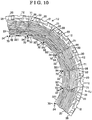
- a configuration of the cooling passage 71 which is provided between the three-phase windings 20, 20, differs from that of the first embodiment. More specifically, in the second embodiment, a correlation distance between the adjoining windings 20, 20 at the cooling passage 71 is set to become gradually shorter from a supply side toward a discharge side, and thus the cooling passage 71 is formed so that a flow path of the cooling medium at the discharge side is narrower than that at the supply side of the cooling medium.
- the identical numerical designations are given to identical parts, portions and the like to those of the first embodiment, thereby omitting duplicated description of these parts or portions.
- Fig. 9 the split cores 11, 11 for two phases are cut in the axial direction and the cooling passage 71 provided between the corresponding windings 20, 20 is schematically illustrated.
- the supply side of the cooling medium is indicated with a direction of an arrow D1 and the discharge side of the cooling medium is indicated with a direction of an arrow D2. That is, the cooling medium is supplied from the side indicated with the direction of the arrow D1 to the side indicated with the direction of the arrow D2 (that is, in the direction of the arrow D).
- a boundary between a heat exchange surface of each of the winding 20, 20 and the cooling medium is referred to as a boundary layer BL1 and a boundary layer BL2, respectively.
- each of the windings 20, 20 is wound three times around the corresponding first bobbin 30 and the corresponding second bobbin 40, and a state where the windings 20, 20 are wound is illustrated with the three-layered annular rings.
- thickness of a portion at which the winding 20 is wound around is configured to be smallest at the supply side of the cooling medium (the side indicated with the direction of the arrow D1) and becomes gradually larger toward the discharge side of the cooling medium (the side indicated with the direction of the arrow D2). More specifically, at the core holding portion 41 of the second bobbin 40, the thickness of the portion at which the winding 20 is wound around is configured to be smallest at a portion connected to the core supporting portion 42 and to become gradually larger toward the discharge side of the cooling medium (the side indicated with the direction of the arrow D2).
- a circumferential length of the portion at which the thickness of the core holding portion 41 is smallest in the axial direction is referred to as a shortest circumferential length L1.
- thickness of a portion around which the winding 20 is wound is configured to be smallest at a portion connected to the core holding portion 41 and become gradually larger toward the discharge side of the cooling medium (the side indicated with the direction of the arrow D2).
- a circumferential length of the portion at which the thickness of the body portion 31 is longest in the axial direction is referred to as a longest circumferential length L2.
- the longest circumferential length L2 is longer compared to the shortest circumferential length L1.
- a correlation distance G1 between the windings 20, 20 at the cooling passage 71 at the supply side (the side indicated with the direction of the arrow D1) of the cooling medium is longer than a correlation distance G2 between the windings 20, 20 at the cooling passage 71 at the discharge side (the side indicated with the direction of the arrow D2) of the cooling medium.
- an amount of heat removed is proportional to a temperature difference and to a heat transfer area, and is (theoretically) proportional to square root of a flow rate".
- a difference between temperature of the windings 20, 20 and temperature of the cooling medium is larger, and thus a cooling efficiency is higher compared to the discharge side (the side indicated with the direction of the arrow D2) of the cooling medium.
- a flow rate of the cooling medium is set to be lower at the supply side (the side indicated with the direction of the arrow D1) than that at the discharge side (the side indicated with the direction of the arrow D2), sufficient amount of heat is removed.
- the flow rate of the cooling medium is set higher at the discharge side (the side indicated with the direction of the arrow D2) than at the supply side (the side indicated with the direction of the arrow D1) in order to assure the necessary amount of heat removed.
- the correlation distance G1, G2 between the windings 20, 20 at the cooling passage 71 is set to become gradually shorter from the supply side (the side indicated with the direction of the arrow D1) toward the discharge side (the side indicated with the direction of the arrow D2) of the cooling medium supplied to the cooling passage 71, which therefore allows the flow rate of the cooling medium at the discharge side (the side indicated with the direction of the arrow D2) to be higher than that at the supply side (the side indicated with the direction of the arrow D1).
- the flow rate of the cooling medium may be set so as to become gradually higher from the supply side (the side indicated with the direction of the arrow D1) toward the discharge side (the side indicated with the direction of the arrow D2) of the cooling medium, and thus amount of heat removed from the windings 20, 20 is equalized.
- Thickness of each of the boundary layer BL1 and the boundary layer BL2 may change depending on, for example, a resistance of a flow channel of the cooling passage 71 and/or viscosity of the cooling medium, and a required flow rate of the cooling medium may change.
- a method for deriving the correlation distances G1, G2 between the windings 20, 20 at the cooling passage 71 is not limited to any particular method.
- the correlation distances G1, G2 may be derived, for example, by means of a known simulation of a convection heat transfer or through measurement conducted on an actual machine.
- a method for changing the correlation distance G1 and/or G2 between the windings 20, 20 at the cooling passage 71 is not limited to any particular method.
- the correlation distances G1 and/or G2 between the windings 20, 20 at the cooling passage 71 may be changed by winding the windings 20, 20 at the supply side (the side indicated with the direction of the arrow D1) and at the discharge side (the side indicated with the direction of the arrow D2) in different ways from each other.
- the thickness of the portion around which the winding 20 is wound may be gradually changed at the first bobbin 30 and the second bobbin 40.
- the third embodiment differs from the first and second embodiments in that the first bobbin unit 50 and the second bobbin unit 60 are not constituted.
- One of the first bobbins 30 and another one of the first bobbins 30 which are adjoining to each other in the circumferential direction are sealed with each other at the corresponding inner peripheral side end portions 34, 34 of the first bobbins 30, 30.
- One of the second bobbins 40 and another one of the second bobbins 40 which are adjoining to each other in the circumferential direction are sealed with each other at the corresponding inner peripheral side end portions 43, 43 of the second bobbins 40, 40.
- the identical numerical designations are given to identical parts, portions and the like to those of the first and the second embodiments, thereby omitting duplicated description of these parts or portions.
- Fig. 10 six of the first bobbins 30, which correspond to two of the stator units 1U, 1U, are arranged in the circumferential direction.
- One of the first bobbins 30 and another one of the first bobbins 30 which are adjoining to each other in the circumferential direction are sealed with each other at the corresponding inner peripheral side end portions 34, 34 of the first bobbins 30, 30 by means of the first sealing member 70.
- first sealing member 70 is retained in the sandwiched manner between the inner peripheral side end portions 34, 34 of the adjoining first bobbins 30, 30 and between the inner peripheral side end portions 43, 43 of the adjoining second bobbins 40, 40 while the stator 1 is securely fitted in the stator housing 100 by the shrink fitting or the press fitting.
- the material, shape and the like of the first sealing member 70 are similar to those explained in the first and the second embodiments.
- the cooling passage 71 extending in the axial direction is provided between the three-phase windings 20, 20 in a similar manner to that of the first and second embodiments.
- the cooling medium circulates among the three-phase windings 20, and thus each winding 20, which releases the highest amount of heat among the parts and the components of the stator 1, is directly cooled.
- One of the first bobbins 30 and another one of the first bobbins 30 positioned adjoining thereto are sealed with each other at the corresponding inner peripheral side end portions 34, 34 of the first bobbins 30, 30, and one of the second bobbins 40 and another one of the second bobbins 40 positioned adjoining thereto are sealed with each other at the corresponding inner peripheral side end portions 43, 43 of the second bobbins 40, 40. Accordingly, it is restricted that the cooling medium which removes the heat from the winding 20 flows out to the rotor side. Consequently, the heat transfer via the cooling medium to the rotor and the friction loss occurring at the rotor are reduced.
- the manufacturing method of the three-phase rotary electrical machine of the third embodiment includes the assembly process, the winding process and the sealing process, and the stator 1 is manufactured in such an order.
- the assembly process the first bobbin 30 and the second bobbin 40 are attached to single split core 11 from the both ends of the split core 11 in the axial direction, respectively.
- the winding process the winding 20 is wound around the first bobbin 30 and the second bobbin 40, which are attached to the split core 11.
- the first bobbins 30 and the second bobbins 40, around each of which the winding 20 is wound, are arranged along the circumferential direction, and the adjoining first bobbins 30, 30 are sealed with each other at the corresponding inner peripheral side end portions 34, 34, and the adjoining second bobbins 40, 40 are sealed with each other at the corresponding inner peripheral side end portions 43, 43.
- three of the first bobbins 30, 30, 30 may be fixed in a manner that the inner peripheral side surfaces 321, 321, 321 of the three first bobbins 30, 30, 30 are arranged to define the triangular configuration when viewed in the axial direction, and the winding of the winding 20 may be performed.
- the winding of the winding 20 is performed on the second bobbins 40 in a similar manner.
- two bobbins arranged in the circumferential direction may constitute one bobbin unit, and the bobbin unit may be attached at each axial end of the split core.
- the rotor may employ permanent magnet or a winding.
- the rotor employing the permanent magnet does not suffer from temperature rise caused by the heat generated at the winding, and thus does not need to be protected from the heat.
- the three-phase rotary electrical machine may be any of a direct-current machine, a synchronous machine and an induction machine.
- a magnetic force may be adjusted by an energizing current in a case where direct-current energization is applied, and speed may be controlled by frequencies in a case where alternating-current energization is applied.
- Starting characteristic may be changed by a resistance value connected to the winding in case of the induction machine.
- the rotor may be an inner rotor arranged at the radially inner side relative to the stator or may be an outer rotor arranged at a radially outer side relative to the stator.
- An inner rotor includes a low moment of inertia, and therefore the speed of the three-phase electric motor may be easily controlled.
- an outer rotor includes a high moment of inertia, and thus generates a high driving torque, thereby being advantageous in operating at a constant speed.
- a three-phase rotary electrical machine including a stator (1) including a stator core (10) including split cores (11), a rotor (2), a bobbin (30, 40) attached to each of the split cores, a winding (20) being wound around each split core to which the bobbin is attached, and a bobbin unit (50, 60) including three of the bobbins which are arranged in a circumferential direction of a rotation axis (X) as one unit, wherein the bobbin positioned at a center of the bobbin unit are formed in a bendable manner integrally with the bobbins positioned adjoining to the bobbin positioned at the center, the bobbin unit is sealed with the bobbin unit positioned adjoining thereto, and a cooling passage (71) extending In the axial direction is provided at each clearance between the windings for three phases.
Description
- This disclosure relates to a three-phase rotary electrical machine according to the preamble of
claim 1, the features of which are known from documentWO 2010/124534 A1 . - A known stator structure is disclosed in
JP 2009-89456 A - However, the stator structure disclosed in
JP 2009-89456 A - Document
WO 2008/035920 A1 discloses a stator for an electric motor. The stator comprises a plurality of segmented cores each having one yoke and at least one pole protruding from the yokes in a radial direction; a plurality of bobbins formed to receive the poles therein, having blocking walls extending from one side of ends of the poles in a circumferential direction thereby to block a space between the poles, and coupled to the poles; and stator coils wound on the bobbins. Accordingly, the temperature of the stator core and the stator coil are prevented from rising, and a noise occurrence is reduced. Furthermore, a winding operation for the stator coil and a manufacturing process are facilitated. - A need thus exists for a three-phase rotary electrical machine in which a performance of cooling a stator coil including a split core is enhanced and the number of the parts of the stator is reduced.
- It is the object of the invention to provide such a three-phase rotary electrical machine.
- The object of the invention is achieved by a three-phase rotary electrical machine according to
claim 1. Advantageous embodiments are carried out according to the dependent claims. - According to an aspect of this disclosure, a three-phase rotary electrical machine includes a stator including a stator core including split cores split in a circumferential direction of a rotation axis, a rotor arranged coaxially with and facing the stator, a bobbin made of an insulating material and attached to each of the split cores, a winding being wound in a concentrated winding method around each split core to which the bobbin is attached, the winding being provided for each of three phases of the rotary electrical machine, and a bobbin unit including three of the bobbins which are arranged in the circumferential direction as one unit, wherein each bobbin includes inner peripheral side end portions), the inner peripheral side end portions of the bobbin positioned at a center among the three bobbins of the bobbin unit are formed in a bendable manner integrally with the corresponding inner peripheral side portion of each of the bobbins positioned adjoining to the bobbin positioned at the center, the bobbin unit is split in an axial direction of the rotation axis in such a way that the bobbin unit is configured to be attached to three of the split cores from axial ends of the three split cores, and the three of the split cores are attached with the bobbin unit from the axial ends, the bobbin unit is sealed at the corresponding inner peripheral side end portions with the bobbin unit positioned adjoining thereto, and a cooling passage extending in the axial direction is provided at each clearance between the windings for the three phases.
- According to the above described structure, the bobbin unit is sealed with the adjoining bobbin unit at the inner peripheral side end portions, and the cooling passage extending in the axial direction is provided at each clearance between the three-phase windings. Accordingly, cooling medium is allowed to flow between the three-phase windings, and thus each winding, which releases the highest amount of heat among parts and components of the stator, is directly cooled, In addition, the inner peripheral side end portions of the adjoining bobbin units are sealed with each other, and thus it is restricted that the cooling medium, which removes the heat from the winding, flows out to a rotor side. Accordingly, heat transfer via the cooling medium to the rotor and the friction loss occurring at the rotor are reduced.
- According to the above described structure, because the bobbin unit includes the three bobbins which are arranged adjoining to one another in the circumferential direction and are formed integrally with one another into one unit, there is no need to provide the first sealing member at the inner peripheral side end portions of the bobbin positioned at the center and the inner peripheral side end portion of each of the bobbins positioned adjoining to the bobbin positioned at the center. This allows an increased flow path of the cooling medium, thereby enhancing a cooling performance. In addition, an amount of a first sealing member used is reduced to one third of an amount of the
first sealing member 70 that would be used in a case each inner peripheral side end portion of the three bobbins is sealed by means of the first sealing member. In addition, because the three bobbins are formed to be integrated into one unit, the number of parts and components of the stator is reduced. By reducing the number of the parts and the components, reliability is enhanced and costs are reduced. - According to another aspect of this disclosure, the three-phase rotary electrical machine further includes a first sealing member arranged at each of the inner peripheral side end portions of the bobbin unit configured as the one unit.
- According to the above described structure, it is restricted that the cooling medium, which removes the heat from the winding, flows out to a rotor side. Accordingly, heat transfer via the cooling medium to the rotor and friction loss occurring at the rotor are reduced.
- According to a further aspect of this disclosure, the three-phase rotary electrical machine further includes a cooling medium supply cover for pressure-pumping the cooling medium to the cooling passage, the cooling medium supply cover covering one end of the three-phase electrical machine in the axial direction.
- According to the above described structure, one end of the three-phase electrical machine in the axial direction is covered with the cooling medium supply cover, and the cooling medium may be pressure-pumped to the cooling passage via the cooling medium supply cover. Accordingly, there is no need to separately provide a supply passage for supplying the cooling medium, which reduces man-hours and a size of the three-phase rotary electrical machine.
- According to a further aspect of this disclosure, the cooling medium supply cover includes an opening portion facing the cooling passage and configured to discharge the cooling medium to the cooling passage, and a projection portion projecting in a direction of the stator core and engaging with an inner peripheral flange portion and an outer peripheral flange portion of the bobbin.
- According to the above described structure, the cooling medium supply cover includes the projection portion which engages with the inner peripheral flange portion and the outer peripheral flange portion of the bobbin. Accordingly, it is restricted that the cooling medium discharged from the opening portion of the cooling medium supply cover flows toward the rotor and/or toward a stator housing by bringing the bobbin and the cooling medium supply cover in contact with each other at the projection portion.
- According to a further aspect of this disclosure, the opening portion is provided with a pipe arranged for introducing the cooling medium.
- According to the above described structure, the pipe introducing the cooling medium is provided at the opening portion of the cooling medium supply cover. Accordingly, the cooling medium is pressure-pumped via the pipe provided at the cooling medium supply cover to the cooling passage.
- According to a further aspect of this disclosure, the three-phase rotary electrical machine further includes a second sealing member provided each of between the projection portion of the cooling medium supply cover and the inner peripheral flange portion of the bobbin, and between the projection portion of the cooling medium supply cover and the outer peripheral flange portion of the bobbin.
- According to the above described structure, the second sealing member is provided each of between the cooling medium supply cover and the inner peripheral flange portion of the bobbin, and between the projection portion and the outer peripheral flange portion of the bobbin. Accordingly, a sealing performance at an engaging portion between each bobbin and the cooling medium supply cover is enhanced, and thus an effect of restricting outflow of the cooling medium is enhanced.
- According to a further aspect of this disclosure, a correlation distance between the windings at the cooling passage becomes gradually shorter from a supply side toward a discharge side of the cooling medium supplied to the cooling passage.
- It is generally known that "an amount of heat removed is proportional to a heat transfer area and to a temperature difference, and is (theoretically) proportional to square root of a flow rate". At the supply side of the cooling medium, a difference between temperature of the windings and temperature of the cooling medium is larger, and thus a cooling efficiency is higher compared to the discharge side of the cooling medium. Thus, even in a case where a flow rate of the cooling medium is set to be lower at the supply side than that at the discharge side, a sufficient amount of heat is removed. On the other hand, at the discharge side of the cooling medium, the temperature of the cooling medium rises as the cooling medium removes the heat from the windings, and thus the difference between the temperature of the windings and the temperature of the cooling medium becomes smaller, which decreases the cooling efficiency. Therefore, the flow rate of the cooling medium is set higher at the discharge side (the side indicated with the direction of the arrow D2) than at the supply side (the side indicated with the direction of the arrow D1) in order to assure the necessary amount of heat removed.
- According to the above described structure, the correlation distance between the windings at the cooling passage is set to be gradually shorter from the supply side toward the discharge side of the cooling medium supplied to the cooling passage, which therefore allows the flow rate of the cooling medium at the discharge side to be set higher than that at the supply side. Consequently, the flow rate of the cooling medium may be set to become gradually higher from the supply side toward the discharge side of the cooling medium, and thus the amount of the heat removed from the windings is equalized.
- According to a further aspect of this disclosure, a manufacturing method of a three-phase rotary electrical machine, the three-phase rotary electrical machine including a stator including a stator core including split cores split in a circumferential direction of a rotation axis, a rotor arranged coaxially with and facing the stator, a bobbin made of an insulating material and attached to each of the split cores, a winding being wound in a concentrated winding method around each split core to which the bobbin is attached, a bobbin unit including three of the bobbin which are arranged in the circumferential direction as one unit, wherein each bobbin includes inner peripheral side end portions, the inner peripheral side end portions of the bobbin positioned at a center among the three bobbins of the bobbin unit are formed in a bendable manner integrally with the corresponding inner peripheral side portion of each of the bobbins positioned adjoining to the bobbin positioned at the center, and the bobbin unit is split in an axial direction of the rotation axis in such a way that the bobbin unit is configured to be attached to three of the split cores from axial ends of the three split cores, the manufacturing method of the three-phase rotary electrical machine includes an assembly process for attaching the bobbin unit to the three of the split cores from the axial ends of the split core, a winding process for arranging inner peripheral side surfaces of the bobbin unit, which is attached to the three of the split cores, in a triangular configuration when viewed in the axial direction and for winding the winding, and a sealing process for arranging the bobbin unit, around which the winding is wound, along the circumferential direction, and for sealing the bobbin unit and the bobbin unit positioned adjoining thereto with each other at the inner peripheral side end portions.
- According to the above described structure, because the winding is performed in the state where the inner peripheral side surfaces of each bobbin unit attached to the three split cores are arranged to define the triangular configuration when viewed in the axial direction, while the winding is being performed on one of the three phases, it is restricted that the bobbins for other phases interfere with the bobbin for the phase on which the winding is being performed, and thus the operation efficiency is enhanced. In addition, by performing the winding in the state where the triangular configuration is defined, the windings for two or three phases may be wound at the same time.
- According to a further aspect of this disclosure, a manufacturing method of a three-phase rotary electrical machine, the three-phase rotary electrical machine including a stator including a stator core including split cores split in a circumferential direction of a rotation axis, a rotor arranged coaxially with and facing the stator, a bobbin made of an insulating material and attached to each of the split cores, a winding being wound in a concentrated winding method around each split core to which the bobbin is attached, a bobbin unit including three of the bobbin which are arranged in the circumferential direction as one unit, wherein each bobbin includes inner peripheral side end portions, each inner peripheral side end portion of each bobbin is formed in a bendable manner integrally with the corresponding inner peripheral side portion of the adjoining bobbins, inner peripheral side surfaces define a triangular configuration when viewed in an axial direction of the rotation axis, and the bobbin unit is split in the axial direction in such a way that the bobbin unit is configured to be attached to three of the split cores from axial ends of the three split cores, the manufacturing method of the three-phase rotary electrical machine including an assembly process for attaching the bobbin unit to the three of the split cores from axial ends of the split core, a winding process for winding the winding around the bobbin unit which is attached to the split cores, a cutting process for cutting one of apices of the triangular configuration after the winding is wound, and a sealing process for arranging the bobbin unit, where the one of the apices of the triangular configuration is cut, along the circumferential direction and for sealing the bobbin unit and the bobbin unit positioned adjoining thereto with each other at the inner peripheral side end portions.
- According to the above described structure, the winding is wound around the bobbin unit each of which is constituted by the three of the bobbins arranged in the circumferential direction as one unit. The winding is performed by using the bobbin unit where each inner peripheral side end portion of each bobbin is formed in the bendable manner integrally with the corresponding inner peripheral side portion of the adjoining bobbins, and the inner peripheral side surfaces of the bobbin unit are arranged to define the triangular configuration when viewed in the axial direction. One of the apices of the triangular configuration is cut out after completion of the winding, and therefore there is no need to bring the inner peripheral side end portions of the circumferential ends of the bobbin unit to be in contact with each other in order to form the triangular configuration before performing the winding, and thus the operation efficiency is enhanced. In addition, the split cores and the bobbin unit are easily assembled to each other.
- According to a further aspect of this disclosure, a three-phase rotary electrical machine includes a stator including a stator core including split cores split in a circumferential direction of a rotation axis, a rotor arranged coaxially with and facing the stator, and a bobbin made of an insulating material and attached to each of the split cores, a winding being wound in a concentrated winding method around each split core to which the bobbin is attached, the winding being provided for each of three phases of the rotary electrical machine, wherein each bobbin includes inner peripheral side end portions, the bobbin attached to one of the split cores and the bobbin attached to another one of the split cores positioned adjoining to the one of the split cores are sealed with each other at the corresponding inner peripheral side end portions, and a cooling passage extending in an axial direction of the rotation axis is provided at each clearance between the windings for the three phases.
- According to the above described structure, the bobbin attached to one of the split cores and the bobbin attached to another one of the split cores positioned adjoining to the one of the split cores are sealed with each other at the corresponding inner peripheral side end portions, and the cooling passage extending in the axial direction is provided at each clearance between the three-phase windings. Accordingly, the cooling medium is allowed to flow between the three-phase windings, and thus each winding, which releases the highest amount of heat among parts and components of the stator, is directly cooled. In addition, the bobbin and the bobbin positioned adjoining thereto are sealed with each other at the inner peripheral side end portions, and therefore it is restricted that the cooling medium which removes the heat from the winding flows out to the rotor side. Accordingly, the heat transfer via the cooling medium to the rotor and the friction loss occurring at the rotor are reduced.
- According to a further aspect of this disclosure, the three-phase rotary electrical machine further includes a first sealing member arranged at each of the inner peripheral side end portions of the bobbin attached to the one of the split cores and the bobbin attached to the another one of the split cores positioned adjoining to the one of the split cores.
- According to the above described structure, it is restricted that the cooling medium, which removes the heat from the winding, flows out to the rotor side. Accordingly, the heat transfer via the cooling medium to the rotor and the friction loss occurring at the rotor are reduced.
- The foregoing and additional features and characteristics of this disclosure will become more apparent from the following detailed description considered with the reference to the accompanying drawings, wherein;
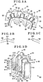
-
Fig. 1 is a perspective view schematically illustrating a part of a stator of embodiments disclosed here; -
Fig. 2A is a perspective view schematically illustrating a structure of a first bobbin of the embodiments; -
Fig. 2B is a perspective view schematically illustrating a split core of the embodiments; -
Fig. 2C is a perspective view schematically illustrating a structure of a second bobbin of the embodiments; -
Fig. 3A is a perspective view schematically illustrating a first bobbin unit of the embodiments; -
Fig. 3B is an enlarged view of a portion A ofFig. 3A ; -
Fig. 3C is an enlarged view of a portion B ofFig. 3A ; -
Fig. 3D is a perspective view schematically illustrating a second bobbin unit of the embodiments; -
Fig. 4A is a perspective view explaining part of an assembly process of a stator of the embodiments, where the second bobbin unit is illustrated; -
Fig. 4B is a perspective view explaining part of the assembly process of the stator of the embodiments, illustrating a state where the split core is attached to the second bobbin unit; -
Fig. 5A is a perspective view explaining the assembly process of the stator of the embodiments, where the first bobbin unit Is illustrated; -
Fig. 5B is a perspective view explaining the assembly process of the stator of the embodiments, where the first bobbin unit and the second bobbin unit are attached to the split core is illustrated; -
Fig. 5C is a perspective view explaining a winding process of the stator of the embodiments, where a winding for one phase is wound; -
Fig. 6A is a perspective view explaining a state after the winding is completed according to the embodiments; -
Fig. 6B is a top view explaining the state after the winding is completed according to the embodiments: -
Fig. 6C is an enlarged view of a portion C ofFig. 6B ; -
Fig. 7 is a top view schematically illustrating part of the stator of the embodiments; -
Fig. 8 is a cross-sectional view illustrating an example of a three-phase electric motor of the embodiments; -
Fig. 9 is a cross-sectional view, viewed in a radial direction of the stator, explaining a cooling passage of the second embodiment disclosed here; and -
Fig. 10 is a top view schematically illustrating part of a stator of the third embodiment disclosed here. - First, second and third embodiments related to this disclosure will be explained with reference to the accompanying drawings. In the embodiments, identical reference numerals designate the identical or corresponding portions or parts, and therefore, duplicated description of these portions or parts is omitted. Each of the accompanying drawings schematically illustrates the embodiments, however, the accompanying drawings do not specify sizes of structures in detail.
- (1) A structure of the three-phase rotary electrical machine of a first embodiment will be explained hereunder with reference to
Figs. 1 to 3D . - The three-phase rotary electrical machine of the first embodiment is provided with a
stator 1, and arotor 2 which will be explained later (refer toFig. 8 ). Thestator 1 includes astator core 10 includingsplit cores 11 in a circumferential direction of a rotation axis X. Therotor 2 is arranged coaxially with thestator 1 to face thestator 1. A winding 20, that is, a three-phase winding, is wound around thesplit core 11 in a concentrated winding method. InFig. 1 , three of thesplit cores split cores split cores stator unit 1U as illustrated inFig. 1 . - The spilt
core 11 is constituted by plural core sheets, each of which is made of an electromagnetic steel sheet, laminated in a radial direction of thestator 1. As illustrated inFig. 2B , each splitcore 11 includes ayoke portion 12 extending in the circumferential direction and ateeth portion 13 protruding from an inner peripheral side surface of theyoke portion 12 toward a direction of the rotation axis X and defining a magnetic pole. At an end portion of theteeth portion 13, a facingportion 131 which is shaped to be wide in the circumferential direction and is configured to face an outer peripheral surface of therotor 2. - A round wire having a round cross section is used for the winding 20. A surface of an electrical conductor is protected with an insulating layer including, for example, an enamel coating. Instead of the round wire, thin wires having various shapes of cross section may be used as the winding 20 including, for example, a rectangular wire having a polygon shaped-cross section. Parallel thin wires, which are constituted by plural thin wires arranged parallel to one another, may also be used as the winding 20.
- The
split core 11 is held in a sandwiched manner by a first bobbin 30 (serving as a bobbin) and a second bobbin 40 (serving as the bobbin), which are arranged at both sides of thesplit core 11 in the axial direction, respectively. Thefirst bobbin 30 and thesecond bobbin 40 are made of an insulating material including, for example, resin, and are formed by injection molding. In this specification, a term "bobbin" refers to an insulating member electrically insulating thestator core 10 and the winding 20 from each other, and is also referred to as an insulator. As illustrated inFig. 2A , thefirst bobbin 30 includes abody portion 31 around which the winding 20 is wound, an innerperipheral flange portion 32 provided at an inner peripheral side surface of thebody portion 31 and extending in the axial direction, and an outerperipheral flange portion 33 provided at an outer peripheral side surface of thebody portion 31 and extending in the axial direction. The innerperipheral flange portion 32 and the outerperipheral flange portion 33 are formed integrally with thebody portion 31 so as to face each other. Thefirst bobbin 30 is provided with a recessed portion and is configured to be attached to theteeth portion 13 from the axial direction in a manner that thefirst bobbin 30 partly covers theteeth portion 13. Circumferential end portions of the innerperipheral flange portion 32 are hereinafter referred to simply as inner peripheralside end portions first bobbin 30. Circumferential end portions of the outerperipheral flange portion 33 are hereinafter referred to simply as outer peripheralside end portions first bobbin 30. - As illustrated in
Fig. 2C , thesecond bobbin 40 includes acore holding portion 41 configured to hold theteeth portion 13 in the circumferential direction so that theteeth portion 13 fits in thecore holding portion 41, and acore supporting portion 42 provided at thecore holding portion 41 integrally therewith in the axial direction and is configured to support theteeth portion 13. Inner peripheral side end portions of thecore holding portion 41 are bent in the circumferential direction to define inner peripheral side bentportions core holding portion 41 are bent in the circumferential direction to define outer peripheral side bentportions portions portion 131 of thesplit core 11, and the outer peripheral side bentportions yoke portion 12 of thesplit core 11. Circumferential end portions of thecore supporting portion 42 extend in the axial direction and define sidesurface supporting portions surface supporting portions portions surface supporting portions side end portions second bobbin 40. Circumferential end portions of the outer peripheral side bentportions side end portions second bobbin 40. - As illustrated in
Fig. 3A , at one side of the three split cores11, 11, 11 in the axial direction, afirst bobbin unit 50 is constituted by three of thefirst bobbins first bobbin unit 50 serves as a bobbin unit. In thefirst bobbin unit 50, the inner peripheralside end portions first bobbin 30 positioned at a center among the threefirst bobbins first bobbin unit 50 are bendably integrated with the corresponding inner peripheralside end portion 34 of each of thefirst bobbins first bobbin 30 positioned at the center, thereby defining firstbent portions side end portions first bobbin 30 positioned at the center are contactable with the corresponding outer peripheralside end portion 35 of each of the adjoiningfirst bobbins Fig. 3B , each firstbent portion 36 includes a first recessedportion 361 formed to be thin-walled and to open toward the outer periphery. Each of thefirst bobbins first bobbins first bobbin unit 50 is pivotable about the corresponding firstbent portion 36 toward the inner periphery. As illustrated inFig. 3C , each of the inner peripheralside end portions first bobbin unit 50 includes a second recessedportion 341 formed to be thin-walled and to open toward the circumferential direction. - As illustrated in
Fig. 3D , at the other side of the threesplit cores second bobbin unit 60 is constituted by three of thesecond bobbins second bobbin unit 60 serves as the bobbin unit. In thesecond bobbin unit 60, the inner peripheralside end portions second bobbin 40 positioned at a center among the threesecond bobbins second bobbin unit 60 are bendably integrated with the corresponding inner peripheralside end portion 43 of each of thesecond bobbins second bobbin 40 positioned at the center, thereby defining secondbent portions side end portions second bobbin 40 positioned at the center are contactable with the corresponding outer peripheralside end portion 44 of each of the adjoiningsecond bobbins bent portion 45 includes a third recessed portion including a similar configuration to that of the firstbent portion 36, that is, the third recessed portion is formed to be thin-walled and to open toward the outer periphery. Each of thesecond bobbins second bobbins second bobbin unit 60 is pivotable about the corresponding secondbent portion 45 toward the inner periphery. Each of the inner peripheralside end portions second bobbin unit 60 includes a fourth recessedportion 431 including a similar configuration to that of the second recessedportion 341, that is, the fourth recessed portion is formed to be thin-walled and to open toward the circumferential direction. - Next, a manufacturing method of the above-explained three-phase rotary electrical machine by using the
split core 11, thefirst bobbin unit 50, thesecond bobbin unit 60 and the winding 20 will be explained in detail with reference toFigs. 4A to 6C . The manufacturing method of the three-phase rotary electrical machine of the first embodiment includes an assembly process, a winding process and a sealing process, and thestator 1 is manufactured in such an order. - The assembly process will be explained below. The assembly process is a process where the
first bobbin unit 50 and thesecond bobbin unit 60 are attached to the threesplit cores split cores Fig. 4A , each of thesecond bobbins second bobbins second bobbin unit 60 is pivoted about the corresponding secondbent portion 45 toward the inner periphery so that the inner peripheralside end portions Fig. 4B , the threesplit cores second bobbin unit 60. - Next, as illustrated in
Fig. 5A , each of thefirst bobbins first bobbins first bobbin unit 50 is pivoted about the corresponding firstbent portion 36 toward the inner periphery so that the inner peripheralside end portions split cores first bobbin unit 50. At this time, a contactingportion 37 at which the inner peripheralside end portions first bobbin unit 50 are in contact with each other and a contactingportion 46 at which the inner peripheralside end portions second bobbin unit 60 are in contact with each other are aligned on a single straight line.Fig. 5B illustrates a state where thefirst bobbin unit 50 and thesecond bobbin unit 60 are attached to the threesplit cores split cores - According to the first embodiment, the
first bobbin unit 50 is attached to the threesplit cores split cores second bobbin unit 60. However, thesecond bobbin unit 60 may be attached to the threesplit cores split cores first bobbin unit 50. Alternatively, the inner peripheralside end portions side end portions Fig. 5B , after the threesplit cores first bobbin unit 50 and thesecond bobbin unit 60 in a sandwiched manner. Further, in a modified embodiment, the second bobbin unit may be formed in a manner that the inner peripheralside end portions bent portions bent portions second bobbins side end portions portion 37, and thus the firstbent portions bent portions first bobbins - The winding process will be explained below. The winding process is a process where inner peripheral side surfaces 321, 321, 321 of the
first bobbin unit 50 attached to the threesplit cores Fig. 5B , and where the winding 20 is wound. The winding of thewindings 20 for the three phases may be performed in a manner that after completion of winding for one phase, the winding is performed for a next phase as illustrated inFig. 5C . Alternatively, the winding of thewindings 20 may be performed for two or three phases at the same time.Figs. 6A to 6C respectively illustrate a state where thewindings 20 for the three phases are wound. - As illustrated in
Figs. 6A and 6C , a feature of the winding process is that the winding is performed in a state where the inner peripheral side surfaces 321, 321, 321 of thefirst bobbin unit 50 are arranged to define the triangular configuration when viewed in the axial direction. Each of the firstbent portions portion 37 corresponds to an apex of the triangular configuration. By performing the winding in the state where the inner peripheral side surfaces 321, 321, 321 are arranged to define the triangular configuration, while the winding is being performed for one of the three phases, it is restricted that the bobbins for other phases interfere with the bobbin for the phase on which the winding is being performed, and thus an operation efficiency is enhanced. In addition, by performing the winding in the state where the triangular configuration is defined, thewindings 20 for two or three phases may be wound at the same time. The inner peripheral side surfaces 321, 321, 321 are not arranged to define an exact triangular configuration when viewed in the axial direction because each innerperipheral side surface 321 is formed to be curved in the circumferential direction, however, the shape defined by the inner peripheral side surfaces 321, 321, 321 is referred to as the triangular configuration in the embodiments for convenience of the explanation. - By arranging the inner peripheral side surfaces 321, 321, 321 of the
first bobbin unit 50 in the triangular configuration when viewed in the axial direction, inner peripheral side surfaces of thesecond bobbin unit 60, which respectively mate with the inner peripheral side surfaces 321, 321, 321, are arranged to define the triangular configuration. Consequently, the winding process also refers to a process where the inner peripheral side surfaces of thesecond bobbin unit 60 are arranged to define the triangular configuration when viewed in the axial direction and where the winding 20 is wound. In this case, each of the inner peripheral side surfaces refers to a surface defined by the inner peripheral side bentportions surface supporting portions bent portions bent portions side end portions side end portions split cores - The sealing process will be explained below. The sealing process is a process where the first and
second bobbin units windings 20 are wound, are arranged In the circumferential direction, and thefirst bobbin unit 50 and thefirst bobbin unit 50 positioned adjoining thereto, and thesecond bobbin unit 60 and thesecond bobbin unit 60 positioned adjoining thereto are respectively sealed with each other at the inner peripheral side portions. As illustrated inFigs. 6B and 6C , in a state where thewindings 20 for the three phases are wound, each of thefirst bobbins portion 37 is pivoted about the respective firstbent portion 36 in a manner that an opened portion of the firstbent portion 36 is narrowed. By pivoting thefirst bobbins stator unit 1U which is illustrated inFig. 1 is obtained. By pivoting thesecond bobbins portion 46 of thesecond bobbin unit 60 in a manner similar to the above, the state of thestator unit 1U which is illustrated inFig. 1 is obtained. In this case, thesecond bobbins bent portions - As illustrated in
Fig. 7 , two of thestator units first bobbin units side end portions member 70. In a similar manner to that of thefirst bobbin unit 50, the two of thesecond bobbin units side end portions member 70. Thefirst sealing member 70 is retained in a sandwiched manner between the inner peripheralside end portions first bobbin units side end portions second bobbin units stator 1 is securely fitted in astator housing 100 by shrink fitting or press fitting. Thefirst sealing member 70 is formed in a shape that matches a shape defined by the inner peripheralside end portions side end portions member 70 having an annular shape when viewed in an axial direction thereof is used because the inner peripheralside end portions side end portions member 70. Each inner peripheralside end portion 34 and each inner peripheralside end portion 43 are formed in an identical configuration to each other, and thus are in fluid communication with each other in the axial direction. Accordingly, the first sealingmember 70 is formed in one piece in the axial direction of thefirst bobbin unit 50 and thesecond bobbin unit 60, however, the first sealingmember 70 may be formed in, for example, two pieces. - In the first embodiment, a
cooling passage 71 extending in the axial direction is provided between the three-phase windings windings 20 for the three phases. Because thecooling passage 71 is provided in the axial direction between the three-phase windings phase windings stator 1, is directly cooled. In addition, the inner peripheralside end portions first bobbin unit 50 are sealed with each other by means of the first sealingmember 70 and the inner peripheralside end portions second bobbin unit 60 are sealed with each other by means of the first sealingmember 70, and thus it is restricted that the cooling medium which removes the heat from the winding 20 flows out to a rotor side. Consequently, heat transfer via or by means of the cooling medium to therotor 2 and friction loss occurring at therotor 2 are reduced. - Because the
first bobbin unit 50 is constituted by the threefirst bobbins member 70 at the inner peripheral side end portions (the firstbent portions 36, 36) between thefirst bobbin 30 positioned at the center and the adjoiningfirst bobbins member 70 used is reduced to one third of an amount of the first sealingmember 70 that would be used in a case each inner peripheral side end portion of the threefirst bobbins member 70. In addition, each firstbent portion 36 is fluid communication in the axial direction, thereby serving as a flow channel of the cooling medium. Thus, a flow passage of the cooling medium is increased, which enhances a cooling performance. In addition, the threefirst bobbins stator 1 is reduced. By reducing the number of the parts and components, reliability is enhanced and costs are reduced. The same also applies to thesecond bobbin unit 60. - <Three-phase rotary electrical machine>
Fig. 8 is a cross-sectional view illustrating an example of the three-phase electric motor. The three-phase electric motor illustrated inFig. 8 is a three phase synchronous motor for driving wheels of a hybrid vehicle, and is sealed with a motor cover 4 (serving as a cooling medium supply cover) in a state where thestator 1 and therotor 2, which are explained above, are contained in amotor housing 3. One end of the three-phase electric motor is connected to a transmission of a vehicle and the other end of the three-phase electric motor is connected to an output shaft of an engine in an engageable and disengageable manner. - The
stator 1 is fixedly mounted on themotor housing 3 with abolt 300 via thestator housing 100. Thestator 1 includes the above-explainedstator units 1U arranged in the circumferential direction of the rotation axis X to form an annular shape. The adjoiningstator units member 70. Thewindings 20 for a same phase are serially-connected with each other. One end of each of the serially-connectedwindings 20 is connected in a Y-connection and the other end of each of the serially-connectedwindings 20 is connected to a vehicle battery via an inverter. Electric power of the vehicle battery is converted into three-phase alternating current by the inverter, and then supplied to the three-phase electric motor for driving therotor 2. Electric power generated by the three-phase rotary electrical machine is charged at the vehicle battery via the inverter. InFig. 8 , thestator 1 is schematically illustrated in order to clearly represent that the cooling medium flows between the three-phase windings Fig. 8 ). - The
rotor 2 is arranged at a radially inner side relative to thestator 1 to face thestator 1 while leaving a predetermined gap therebetween. Therotor 2 is constituted by plural lamination steel plates, and plural pieces of magnet for a field pole are provided on a circumference of therotor 2. Therotor 2 is fixedly arranged coaxially with ashaft 5 so as to be rotatable. Theshaft 5 is supported viabearings motor housing 3 and the motor cover 4. The motor cover 4 is fixed to themotor housing 3 with thebolt 300. When three-phase alternating current is supplied from the vehicle battery via the inverter to the winding 20, a revolving magnetic field is generated at thestator 1. Thus, therotor 2 is rotated relative to thestator 1 by a magnetic attractive force or a magnetic repulsive force that are caused by the revolting magnetic field. - The motor cover 4 is formed with a pipe 400 (serving as a pipe) protruding in the direction of the rotation axis X for discharging the cooling medium. The
pipe 400 is connected to anoutlet port 600 of apump 6. Aninlet port 601 of thepump 6 is connected by means of apipe 401 to areservoir 7. Thereservoir 7 reserves the cooling medium for cooling thewindings 20 of thestator 1. As the cooling medium, a coolant material including, for example, oil, air or nitrogen may be used. InFig. 8 , thepump 6 and thereservoir 7 are provided separately from the three-phase electric motor, however, in an actual use, thepump 6 is provided integrally with the three-phase electric motor and thereservoir 7 is formed inside themotor housing 3. - Axial end portions of the
second bobbin unit 60 is connected to the motor cover 4 via O-rings pump 6 does not leak out in a direction of therotor 2 or in the direction of thestator housing 100. The axial end portions of thesecond bobbin unit 60 serve as the inner peripheral flange portion and the outer peripheral flange portion, respectively. The O-rings Fig. 8 , a portion of the motor cover 4, the portion which projects in a direction of thestator 1, serves as a projection portion. The cooling medium delivered from thepump 6 is introduced to thepipe 400 and is discharged via an opening portion 402 (serving as an opening portion) of thepipe 400 toward thewindings 20 of thestator 1. The cooling medium flows between the three-phase windings reservoir 7 via a piping. As the cooling medium passes between the three-phase windings - According to the three-phase electric motor of the embodiment, the inner peripheral side end portions of the adjoining
stator units member 70, and thus it is restricted that the cooling medium flowing between the three-phase windings rotor 2. Consequently, the heat transfer via the cooling medium to therotor 2, and the friction loss occurring at therotor 2 are reduced. In order to further restrict the cooling medium from flowing out in the direction of therotor 2, a cover similar to the motor cover 4 may be arranged at a side where the cooling medium is discharged, so that the innerperipheral flange portion 32 and the outerperipheral flange portion 33 of thefirst bobbin unit 50 engage with a projection portion similar to the projection portion formed at the motor cover 4. - (2) The second embodiment will be explained hereunder. In the second embodiment, a configuration of the
cooling passage 71, which is provided between the three-phase windings windings cooling passage 71 is set to become gradually shorter from a supply side toward a discharge side, and thus thecooling passage 71 is formed so that a flow path of the cooling medium at the discharge side is narrower than that at the supply side of the cooling medium. In the second embodiment, the identical numerical designations are given to identical parts, portions and the like to those of the first embodiment, thereby omitting duplicated description of these parts or portions. - In
Fig. 9 , thesplit cores cooling passage 71 provided between the correspondingwindings Fig. 9 , the supply side of the cooling medium is indicated with a direction of an arrow D1 and the discharge side of the cooling medium is indicated with a direction of an arrow D2. That is, the cooling medium is supplied from the side indicated with the direction of the arrow D1 to the side indicated with the direction of the arrow D2 (that is, in the direction of the arrow D). A boundary between a heat exchange surface of each of the winding 20, 20 and the cooling medium is referred to as a boundary layer BL1 and a boundary layer BL2, respectively. For convenience of the explanation, each of thewindings first bobbin 30 and the correspondingsecond bobbin 40, and a state where thewindings - As illustrated in
Fig. 9 , at thefirst bobbin 30 and thesecond bobbin 40, thickness of a portion at which the winding 20 is wound around is configured to be smallest at the supply side of the cooling medium (the side indicated with the direction of the arrow D1) and becomes gradually larger toward the discharge side of the cooling medium (the side indicated with the direction of the arrow D2). More specifically, at thecore holding portion 41 of thesecond bobbin 40, the thickness of the portion at which the winding 20 is wound around is configured to be smallest at a portion connected to thecore supporting portion 42 and to become gradually larger toward the discharge side of the cooling medium (the side indicated with the direction of the arrow D2). A circumferential length of the portion at which the thickness of thecore holding portion 41 is smallest in the axial direction (that is, the portion connected to the core supporting portion 42) is referred to as a shortest circumferential length L1. - At the
body portion 31 of thefirst bobbin 30, thickness of a portion around which the winding 20 is wound is configured to be smallest at a portion connected to thecore holding portion 41 and become gradually larger toward the discharge side of the cooling medium (the side indicated with the direction of the arrow D2). A circumferential length of the portion at which the thickness of thebody portion 31 is longest in the axial direction is referred to as a longest circumferential length L2. Thus, at thefirst bobbin 30 and thesecond bobbin 40, because the thickness of the portion around which the winding 20 is wound is configured to gradually change, the longest circumferential length L2 is longer compared to the shortest circumferential length L1. Accordingly, in a state where thewindings first bobbin 30 and around thesecond bobbin 40, a correlation distance G1 between thewindings cooling passage 71 at the supply side (the side indicated with the direction of the arrow D1) of the cooling medium is longer than a correlation distance G2 between thewindings cooling passage 71 at the discharge side (the side indicated with the direction of the arrow D2) of the cooling medium. - It is generally known that "an amount of heat removed is proportional to a temperature difference and to a heat transfer area, and is (theoretically) proportional to square root of a flow rate". At the supply side (the side indicated with the direction of the arrow D1) of the cooling medium, a difference between temperature of the
windings windings windings - According to the second embodiment, the correlation distance G1, G2 between the
windings cooling passage 71 is set to become gradually shorter from the supply side (the side indicated with the direction of the arrow D1) toward the discharge side (the side indicated with the direction of the arrow D2) of the cooling medium supplied to thecooling passage 71, which therefore allows the flow rate of the cooling medium at the discharge side (the side indicated with the direction of the arrow D2) to be higher than that at the supply side (the side indicated with the direction of the arrow D1). Consequently, the flow rate of the cooling medium may be set so as to become gradually higher from the supply side (the side indicated with the direction of the arrow D1) toward the discharge side (the side indicated with the direction of the arrow D2) of the cooling medium, and thus amount of heat removed from thewindings - Thickness of each of the boundary layer BL1 and the boundary layer BL2 may change depending on, for example, a resistance of a flow channel of the
cooling passage 71 and/or viscosity of the cooling medium, and a required flow rate of the cooling medium may change. Thus, it is favorable to derive in advance the correlation distances G1, G2 between thewindings cooling passage 71 in consideration of the resistance of the flow channel of thecooling passage 71 and/or the viscosity of the cooling medium. A method for deriving the correlation distances G1, G2 between thewindings cooling passage 71 is not limited to any particular method. The correlation distances G1, G2 may be derived, for example, by means of a known simulation of a convection heat transfer or through measurement conducted on an actual machine. - In addition, a method for changing the correlation distance G1 and/or G2 between the
windings cooling passage 71 is not limited to any particular method. For example, the correlation distances G1 and/or G2 between thewindings cooling passage 71 may be changed by winding thewindings first bobbin 30 and thesecond bobbin 40. - (3) The third embodiment will be explained hereunder. The third embodiment differs from the first and second embodiments in that the
first bobbin unit 50 and thesecond bobbin unit 60 are not constituted. One of thefirst bobbins 30 and another one of thefirst bobbins 30 which are adjoining to each other in the circumferential direction are sealed with each other at the corresponding inner peripheralside end portions first bobbins second bobbins 40 and another one of thesecond bobbins 40 which are adjoining to each other in the circumferential direction are sealed with each other at the corresponding inner peripheralside end portions second bobbins - In
Fig. 10 , six of thefirst bobbins 30, which correspond to two of thestator units first bobbins 30 and another one of thefirst bobbins 30 which are adjoining to each other in the circumferential direction are sealed with each other at the corresponding inner peripheralside end portions first bobbins member 70. In a similar manner to that of thefirst bobbins 30, one of thesecond bobbins 40 and another one of thesecond bobbins 40 which are adjoining to each other in the circumferential direction are sealed with each other at the corresponding inner peripheralside end portions second bobbins member 70. Thefirst sealing member 70 is retained in the sandwiched manner between the inner peripheralside end portions first bobbins side end portions second bobbins stator 1 is securely fitted in thestator housing 100 by the shrink fitting or the press fitting. The material, shape and the like of the first sealingmember 70 are similar to those explained in the first and the second embodiments. - In the third embodiment, the
cooling passage 71 extending in the axial direction is provided between the three-phase windings phase windings 20, and thus each winding 20, which releases the highest amount of heat among the parts and the components of thestator 1, is directly cooled. One of thefirst bobbins 30 and another one of thefirst bobbins 30 positioned adjoining thereto are sealed with each other at the corresponding inner peripheralside end portions first bobbins second bobbins 40 and another one of thesecond bobbins 40 positioned adjoining thereto are sealed with each other at the corresponding inner peripheralside end portions second bobbins - The manufacturing method of the three-phase rotary electrical machine of the third embodiment includes the assembly process, the winding process and the sealing process, and the
stator 1 is manufactured in such an order. In the assembly process, thefirst bobbin 30 and thesecond bobbin 40 are attached tosingle split core 11 from the both ends of thesplit core 11 in the axial direction, respectively. In the winding process, the winding 20 is wound around thefirst bobbin 30 and thesecond bobbin 40, which are attached to thesplit core 11. In the sealing process, thefirst bobbins 30 and thesecond bobbins 40, around each of which the winding 20 is wound, are arranged along the circumferential direction, and the adjoiningfirst bobbins side end portions second bobbins side end portions first bobbins first bobbins second bobbins 40 in a similar manner. - (4) Others This disclosure is not limited to the embodiments that are described above and are illustrated in the drawings, and may be appropriately changed or modified without departing from the subject matter of the disclosure. For example, two bobbins arranged in the circumferential direction may constitute one bobbin unit, and the bobbin unit may be attached at each axial end of the split core.
- The rotor may employ permanent magnet or a winding. The rotor employing the permanent magnet does not suffer from temperature rise caused by the heat generated at the winding, and thus does not need to be protected from the heat. Further, the three-phase rotary electrical machine may be any of a direct-current machine, a synchronous machine and an induction machine. A magnetic force may be adjusted by an energizing current in a case where direct-current energization is applied, and speed may be controlled by frequencies in a case where alternating-current energization is applied. Starting characteristic may be changed by a resistance value connected to the winding in case of the induction machine.
- The rotor may be an inner rotor arranged at the radially inner side relative to the stator or may be an outer rotor arranged at a radially outer side relative to the stator. An inner rotor includes a low moment of inertia, and therefore the speed of the three-phase electric motor may be easily controlled. On the other hand, an outer rotor includes a high moment of inertia, and thus generates a high driving torque, thereby being advantageous in operating at a constant speed.
- A three-phase rotary electrical machine including a stator (1) including a stator core (10) including split cores (11), a rotor (2), a bobbin (30, 40) attached to each of the split cores, a winding (20) being wound around each split core to which the bobbin is attached, and a bobbin unit (50, 60) including three of the bobbins which are arranged in a circumferential direction of a rotation axis (X) as one unit, wherein the bobbin positioned at a center of the bobbin unit are formed in a bendable manner integrally with the bobbins positioned adjoining to the bobbin positioned at the center, the bobbin unit is sealed with the bobbin unit positioned adjoining thereto, and a cooling passage (71) extending In the axial direction is provided at each clearance between the windings for three phases.
Claims (6)
- A three-phase rotary electrical machine, comprising:a stator (1) including a stator core (10) including split cores (11) split in a circumferential direction of a rotation axis (X);a rotor (2) arranged coaxially with and facing the stator (1);first and second bobbins (30, 40) made of an insulating material and attached to each of the split cores (11), a winding (20) being wound in a concentrated winding method around each split core (11) to which the respective bobbin (30, 40) is attached, the winding (20) being provided for each of three phases of the rotary electrical machine;a first bobbin unit (50) being constituted by three of the first bobbins (30, 30, 30) which are arranged in the circumferential direction as one unit; anda second bobbin unit (60) being constituted by three of the second bobbins (40, 40, 40) which are arranged in the circumferential direction as one unit; whereineach bobbin (30, 40) includes inner peripheral side end portions (34, 43), the inner peripheral side end portions (34, 43) of the bobbin (30, 40) positioned at a center among the three bobbins (30, 40) constituting the bobbin unit (50, 60) are formed in a bendable manner integrally with the corresponding inner peripheral side portion (34, 43) of each of the bobbins (30, 40) positioned adjoining to the bobbin (30, 40) positioned at the center, the bobbin unit (50, 60) is split in an axial direction of the rotation axis (X) in such a way that the bobbin unit (50, 60) is configured to be attached to three of the split cores (11) from axial ends of the three split cores (11),the three of the split cores (11) are attached with the bobbin unit (50, 60) from the axial ends, the bobbin unit (50, 60) is sealed at the corresponding inner peripheral side end portions (34, 43) with the bobbin unit (50, 60) positioned adjoining thereto, anda cooling passage (71) extending in the axial direction is provided at each clearance between the windings (20) for the three phases,characterized in thata sealing member (70) is retained in a sandwiched manner between the inner peripheral side end portions (34, 34) of the first bobbin unit (50) and between the inner peripheral side end portions (43, 43) of the second bobbin unit (60).
- The three-phase rotary electrical machine according to claim 1, further comprising:
a cooling medium supply cover (4) for pressure-pumping a cooling medium to the cooling passage (71), the cooling medium supply cover (4) covering one end of the three-phase electrical machine in the axial direction. - The three-phase rotary electrical machine according to claim 2, wherein the cooling medium supply cover (4) includes an opening portion (402) facing the cooling passage (71) and configured to discharge the cooling medium to the cooling passage (71), and a projection portion projecting in a direction of the stator core (10) and engaging with an inner peripheral flange portion (32) and an outer peripheral flange portion (33) of the bobbin (30, 40).
- The three-phase rotary electrical machine according to claim 3, wherein the opening portion (402) is provided with a pipe (400) arranged for introducing the cooling medium.
- The three-phase rotary electrical machine according to claim 3, further comprising:
a second sealing member (8) provided each of between the projection portion of the cooling medium supply cover (4) and the inner peripheral flange portion (32) of the bobbin (30, 40), and between the projection portion and the outer peripheral flange portion (33) of the bobbin (30, 40). - The three-phase rotary electrical machine according to any one of claims 1 to 5, wherein a correlation distance (G1, G2) between the windings (20) at the cooling passage (71) becomes gradually shorter from a supply side (D1) toward a discharge side (D2) of the cooling medium supplied to the cooling passage (71).
Applications Claiming Priority (2)
| Application Number | Priority Date | Filing Date | Title |
|---|---|---|---|
| JP2011196931 | 2011-09-09 | ||
| JP2012152077A JP6079012B2 (en) | 2011-09-09 | 2012-07-06 | 3-phase rotating electric machine |
Publications (3)
| Publication Number | Publication Date |
|---|---|
| EP2568574A2 EP2568574A2 (en) | 2013-03-13 |
| EP2568574A3 EP2568574A3 (en) | 2017-09-27 |
| EP2568574B1 true EP2568574B1 (en) | 2019-04-24 |
Family
ID=46851838
Family Applications (1)
| Application Number | Title | Priority Date | Filing Date |
|---|---|---|---|
| EP12183440.2A Not-in-force EP2568574B1 (en) | 2011-09-09 | 2012-09-07 | Three-phase rotary electrical machine and manufacturing method thereof |
Country Status (3)
| Country | Link |
|---|---|
| US (1) | US8853910B2 (en) |
| EP (1) | EP2568574B1 (en) |
| JP (1) | JP6079012B2 (en) |
Cited By (2)
| Publication number | Priority date | Publication date | Assignee | Title |
|---|---|---|---|---|
| WO2023194344A1 (en) * | 2022-04-06 | 2023-10-12 | Brose Fahrzeugteile SE & Co. Kommanditgesellschaft, Würzburg | Stator and electric motor comprising a stator of this type |
| US11837917B2 (en) | 2022-01-28 | 2023-12-05 | Ge Aviation Systems Llc | Method and apparatus for cooling a rotor assembly |
Families Citing this family (13)
| Publication number | Priority date | Publication date | Assignee | Title |
|---|---|---|---|---|
| KR101317892B1 (en) * | 2011-01-24 | 2013-10-16 | 주식회사 아모텍 | Amorphous Stator and Producing Method thereof |
| CN104079086A (en) * | 2013-03-29 | 2014-10-01 | 珠海格力节能环保制冷技术研究中心有限公司 | Stator, motor with stator and compressor |
| GB2525157B (en) * | 2014-02-18 | 2016-08-24 | Yasa Motors Ltd | Machine cooling systems |
| JP2015162975A (en) * | 2014-02-27 | 2015-09-07 | シンフォニアテクノロジー株式会社 | Stator and inner rotor type motor |
| GB2533154B (en) * | 2014-12-12 | 2017-06-07 | Protean Electric Ltd | A coil winding arrangement |
| KR102408250B1 (en) * | 2015-07-21 | 2022-06-13 | 엘지이노텍 주식회사 | Rotor and Motor having the same |
| DE102016209752A1 (en) * | 2016-06-03 | 2017-12-07 | Continental Automotive Gmbh | Cooling an electric machine |
| JP7056563B2 (en) * | 2016-08-18 | 2022-04-19 | 日本電産株式会社 | motor |
| CN107786021B (en) * | 2016-08-29 | 2019-10-11 | 光宝电子(广州)有限公司 | Insulating sleeve with around wire work |
| EP3316454A1 (en) * | 2016-10-25 | 2018-05-02 | HILTI Aktiengesellschaft | Roll support and stator |
| DE102017102495A1 (en) * | 2017-02-08 | 2018-08-09 | Nidec Corporation | Stator for an electric motor |
| CN111628591A (en) * | 2019-02-28 | 2020-09-04 | 株式会社村田制作所 | Stator, stator assembly and converter of electric energy and mechanical energy |
| KR20230023836A (en) * | 2021-08-09 | 2023-02-20 | 주식회사 아모텍 | Stator Having Busbar Structure, Motor for Driving Propeller Using the Same and Method for Manufacturing the Stator |
Family Cites Families (23)
| Publication number | Priority date | Publication date | Assignee | Title |
|---|---|---|---|---|
| JP3017085B2 (en) * | 1995-11-02 | 2000-03-06 | 三菱電機株式会社 | Rotating electric machine and method of manufacturing the same |
| US6259347B1 (en) * | 1997-09-30 | 2001-07-10 | The United States Of America As Represented By The Secretary Of The Navy | Electrical power cooling technique |
| EP1168571A3 (en) | 2000-05-30 | 2003-12-17 | BAE SYSTEMS Controls, Inc. | Rotating machine having hollow stator field windings for coolant flow therein |
| JP3603784B2 (en) * | 2000-12-14 | 2004-12-22 | 日産自動車株式会社 | Rotating electric machine |
| JP3624825B2 (en) * | 2000-12-14 | 2005-03-02 | 日産自動車株式会社 | Rotating electric machine and method of manufacturing rotating electric machine |
| US6870292B2 (en) * | 2001-11-28 | 2005-03-22 | Nissan Motor Co., Ltd. | Stator for motor |
| US6608420B2 (en) * | 2002-01-03 | 2003-08-19 | Hsieh Hsin-Mao | Stator of an alternating current motor |
| JP3896883B2 (en) * | 2002-03-28 | 2007-03-22 | 日産自動車株式会社 | Rotating electric machine |
| US20050057106A1 (en) * | 2002-12-10 | 2005-03-17 | Ballard Power Systems Corporation | Methods and systems for electric machines having windings |
| JP3791492B2 (en) * | 2002-12-25 | 2006-06-28 | 株式会社日立製作所 | Rotating electric machine, electric vehicle, and resin insert molding method |
| JP4444639B2 (en) * | 2003-05-08 | 2010-03-31 | アスモ株式会社 | Stator for rotating electrical machine and method for manufacturing the same |
| DE50303111D1 (en) * | 2003-07-12 | 2006-06-01 | Grundfos As | Segmented stator |
| JP4410730B2 (en) * | 2005-06-29 | 2010-02-03 | 三菱電機株式会社 | Rotating electric machine stator, rotating electric machine, and method of manufacturing rotating electric machine stator |
| US8450898B2 (en) * | 2006-09-01 | 2013-05-28 | Resmed Motor Technologies Inc | Insulator for stator assembly of brushless DC motor |
| KR101185353B1 (en) * | 2006-09-21 | 2012-09-21 | 엘지전자 주식회사 | Stator for electric motor and manufacturing method thereof |
| JP4661849B2 (en) | 2007-09-27 | 2011-03-30 | トヨタ自動車株式会社 | Stator structure |
| JP4880559B2 (en) * | 2007-09-28 | 2012-02-22 | 本田技研工業株式会社 | Cooling structure in rotating electrical machines |
| JP5021443B2 (en) * | 2007-12-14 | 2012-09-05 | 日立オートモティブシステムズ株式会社 | Rotating electric machine |
| JP2009153287A (en) * | 2007-12-20 | 2009-07-09 | Sumitomo Electric Ind Ltd | Molded coil for split stator, and method of manufacturing molded coil for stator, and molding device for molding molded coil for stator |
| JP4670942B2 (en) * | 2008-11-21 | 2011-04-13 | トヨタ自動車株式会社 | Rotating electric machine |
| JP2010239776A (en) * | 2009-03-31 | 2010-10-21 | Mitsubishi Heavy Ind Ltd | Rotary electric machine |
| CN201450371U (en) * | 2009-04-29 | 2010-05-05 | 中山大洋电机股份有限公司 | Stator structure of three-phase motor |
| US20120126643A1 (en) * | 2010-11-19 | 2012-05-24 | Ping Zhong | Apparatuses useful for cooling windings of rotor assemblies |
-
2012
- 2012-07-06 JP JP2012152077A patent/JP6079012B2/en not_active Expired - Fee Related
- 2012-09-07 EP EP12183440.2A patent/EP2568574B1/en not_active Not-in-force
- 2012-09-07 US US13/607,141 patent/US8853910B2/en not_active Expired - Fee Related
Non-Patent Citations (1)
| Title |
|---|
| None * |
Cited By (2)
| Publication number | Priority date | Publication date | Assignee | Title |
|---|---|---|---|---|
| US11837917B2 (en) | 2022-01-28 | 2023-12-05 | Ge Aviation Systems Llc | Method and apparatus for cooling a rotor assembly |
| WO2023194344A1 (en) * | 2022-04-06 | 2023-10-12 | Brose Fahrzeugteile SE & Co. Kommanditgesellschaft, Würzburg | Stator and electric motor comprising a stator of this type |
Also Published As
| Publication number | Publication date |
|---|---|
| US8853910B2 (en) | 2014-10-07 |
| EP2568574A2 (en) | 2013-03-13 |
| JP6079012B2 (en) | 2017-02-15 |
| US20130062972A1 (en) | 2013-03-14 |
| EP2568574A3 (en) | 2017-09-27 |
| JP2013070595A (en) | 2013-04-18 |
Similar Documents
| Publication | Publication Date | Title |
|---|---|---|
| EP2568574B1 (en) | Three-phase rotary electrical machine and manufacturing method thereof | |
| US7135802B2 (en) | Claw pole motor stator | |
| JP6402257B2 (en) | Stator coil, stator provided with the same, and rotating electric machine provided with the same | |
| EP1257043B9 (en) | Cooling of electrical machines | |
| JP2008086128A (en) | Rotary electric machine and ac generator | |
| JP6777760B2 (en) | Stator for rotary electric machine and rotary electric machine | |
| WO2016035533A1 (en) | Stator for rotary electric machine and rotary electric machine equipped with same | |
| US20200235627A1 (en) | Rotary electric machine | |
| EP2853017B1 (en) | Stator of a rotating electric machine | |
| CN112583146A (en) | Transverse flux machine | |
| US20090218906A1 (en) | Rotating electric machine and method of manufacturing the same | |
| JP2019161752A (en) | Rotary electric machine stator | |
| US20160226355A1 (en) | Magnetic inductor electric motor | |
| WO2017038326A1 (en) | Rotor, rotating electrical machine provided therewith, and method of manufacturing rotor | |
| JP2010514406A (en) | Stator for multi-phase rotating electrical machine, multi-phase rotating electrical machine having the stator, and method for manufacturing the stator | |
| EP3840186A1 (en) | Rotating electric machine | |
| JP2012196079A (en) | Cooling structure of motor | |
| JP6416655B2 (en) | Rotating electric machine stator | |
| JP5330860B2 (en) | Rotating electric machine | |
| WO2021199376A1 (en) | Stator and dynamo-electric machine | |
| JP7030961B2 (en) | Stator and rotary machine | |
| WO2020246372A1 (en) | Stator of dynamo-electric machine, terminal block, and dynamo-electric machine | |
| JP5988840B2 (en) | Rotating electric machine stator | |
| JP2014100038A (en) | Stator of rotary electric machine | |
| JP6078305B2 (en) | Rotating electric machine stator |
Legal Events
| Date | Code | Title | Description |
|---|---|---|---|
| PUAI | Public reference made under article 153(3) epc to a published international application that has entered the european phase |
Free format text: ORIGINAL CODE: 0009012 |
|
| AK | Designated contracting states |
Kind code of ref document: A2 Designated state(s): AL AT BE BG CH CY CZ DE DK EE ES FI FR GB GR HR HU IE IS IT LI LT LU LV MC MK MT NL NO PL PT RO RS SE SI SK SM TR |
|
| AX | Request for extension of the european patent |
Extension state: BA ME |
|
| STAA | Information on the status of an ep patent application or granted ep patent |
Free format text: STATUS: REQUEST FOR EXAMINATION WAS MADE |
|
| 17P | Request for examination filed |
Effective date: 20170315 |
|
| RBV | Designated contracting states (corrected) |
Designated state(s): AL AT BE BG CH CY CZ DE DK EE ES FI FR GB GR HR HU IE IS IT LI LT LU LV MC MK MT NL NO PL PT RO RS SE SI SK SM TR |
|
| PUAL | Search report despatched |
Free format text: ORIGINAL CODE: 0009013 |
|
| AK | Designated contracting states |
Kind code of ref document: A3 Designated state(s): AL AT BE BG CH CY CZ DE DK EE ES FI FR GB GR HR HU IE IS IT LI LT LU LV MC MK MT NL NO PL PT RO RS SE SI SK SM TR |
|
| AX | Request for extension of the european patent |
Extension state: BA ME |
|
| RIC1 | Information provided on ipc code assigned before grant |
Ipc: H02K 1/14 20060101ALN20170823BHEP Ipc: H02K 15/04 20060101ALI20170823BHEP Ipc: H02K 3/32 20060101ALI20170823BHEP Ipc: H02K 15/095 20060101ALI20170823BHEP Ipc: H02K 3/52 20060101AFI20170823BHEP Ipc: H02K 3/24 20060101ALI20170823BHEP |
|
| STAA | Information on the status of an ep patent application or granted ep patent |
Free format text: STATUS: EXAMINATION IS IN PROGRESS |
|
| 17Q | First examination report despatched |
Effective date: 20180821 |
|
| REG | Reference to a national code |
Ref country code: DE Ref legal event code: R079 Ref document number: 602012059278 Country of ref document: DE Free format text: PREVIOUS MAIN CLASS: H02K0001140000 Ipc: H02K0003520000 |
|
| GRAP | Despatch of communication of intention to grant a patent |
Free format text: ORIGINAL CODE: EPIDOSNIGR1 |
|
| STAA | Information on the status of an ep patent application or granted ep patent |
Free format text: STATUS: GRANT OF PATENT IS INTENDED |
|
| RIC1 | Information provided on ipc code assigned before grant |
Ipc: H02K 1/14 20060101ALN20181217BHEP Ipc: H02K 3/24 20060101ALI20181217BHEP Ipc: H02K 15/095 20060101ALI20181217BHEP Ipc: H02K 15/04 20060101ALI20181217BHEP Ipc: H02K 3/52 20060101AFI20181217BHEP Ipc: H02K 3/32 20060101ALI20181217BHEP |
|
| INTG | Intention to grant announced |
Effective date: 20190109 |
|
| GRAS | Grant fee paid |
Free format text: ORIGINAL CODE: EPIDOSNIGR3 |
|
| GRAA | (expected) grant |
Free format text: ORIGINAL CODE: 0009210 |
|
| STAA | Information on the status of an ep patent application or granted ep patent |
Free format text: STATUS: THE PATENT HAS BEEN GRANTED |
|
| AK | Designated contracting states |
Kind code of ref document: B1 Designated state(s): AL AT BE BG CH CY CZ DE DK EE ES FI FR GB GR HR HU IE IS IT LI LT LU LV MC MK MT NL NO PL PT RO RS SE SI SK SM TR |
|
| REG | Reference to a national code |
Ref country code: GB Ref legal event code: FG4D |
|
| REG | Reference to a national code |
Ref country code: CH Ref legal event code: EP |
|
| REG | Reference to a national code |
Ref country code: AT Ref legal event code: REF Ref document number: 1125296 Country of ref document: AT Kind code of ref document: T Effective date: 20190515 Ref country code: IE Ref legal event code: FG4D |
|
| REG | Reference to a national code |
Ref country code: DE Ref legal event code: R096 Ref document number: 602012059278 Country of ref document: DE |
|
| REG | Reference to a national code |
Ref country code: NL Ref legal event code: MP Effective date: 20190424 |
|
| REG | Reference to a national code |
Ref country code: LT Ref legal event code: MG4D |
|
| PG25 | Lapsed in a contracting state [announced via postgrant information from national office to epo] |
Ref country code: NL Free format text: LAPSE BECAUSE OF FAILURE TO SUBMIT A TRANSLATION OF THE DESCRIPTION OR TO PAY THE FEE WITHIN THE PRESCRIBED TIME-LIMIT Effective date: 20190424 |
|
| PG25 | Lapsed in a contracting state [announced via postgrant information from national office to epo] |
Ref country code: SE Free format text: LAPSE BECAUSE OF FAILURE TO SUBMIT A TRANSLATION OF THE DESCRIPTION OR TO PAY THE FEE WITHIN THE PRESCRIBED TIME-LIMIT Effective date: 20190424 Ref country code: LT Free format text: LAPSE BECAUSE OF FAILURE TO SUBMIT A TRANSLATION OF THE DESCRIPTION OR TO PAY THE FEE WITHIN THE PRESCRIBED TIME-LIMIT Effective date: 20190424 Ref country code: ES Free format text: LAPSE BECAUSE OF FAILURE TO SUBMIT A TRANSLATION OF THE DESCRIPTION OR TO PAY THE FEE WITHIN THE PRESCRIBED TIME-LIMIT Effective date: 20190424 Ref country code: FI Free format text: LAPSE BECAUSE OF FAILURE TO SUBMIT A TRANSLATION OF THE DESCRIPTION OR TO PAY THE FEE WITHIN THE PRESCRIBED TIME-LIMIT Effective date: 20190424 Ref country code: AL Free format text: LAPSE BECAUSE OF FAILURE TO SUBMIT A TRANSLATION OF THE DESCRIPTION OR TO PAY THE FEE WITHIN THE PRESCRIBED TIME-LIMIT Effective date: 20190424 Ref country code: NO Free format text: LAPSE BECAUSE OF FAILURE TO SUBMIT A TRANSLATION OF THE DESCRIPTION OR TO PAY THE FEE WITHIN THE PRESCRIBED TIME-LIMIT Effective date: 20190724 Ref country code: PT Free format text: LAPSE BECAUSE OF FAILURE TO SUBMIT A TRANSLATION OF THE DESCRIPTION OR TO PAY THE FEE WITHIN THE PRESCRIBED TIME-LIMIT Effective date: 20190824 Ref country code: HR Free format text: LAPSE BECAUSE OF FAILURE TO SUBMIT A TRANSLATION OF THE DESCRIPTION OR TO PAY THE FEE WITHIN THE PRESCRIBED TIME-LIMIT Effective date: 20190424 |
|
| PG25 | Lapsed in a contracting state [announced via postgrant information from national office to epo] |
Ref country code: GR Free format text: LAPSE BECAUSE OF FAILURE TO SUBMIT A TRANSLATION OF THE DESCRIPTION OR TO PAY THE FEE WITHIN THE PRESCRIBED TIME-LIMIT Effective date: 20190725 Ref country code: PL Free format text: LAPSE BECAUSE OF FAILURE TO SUBMIT A TRANSLATION OF THE DESCRIPTION OR TO PAY THE FEE WITHIN THE PRESCRIBED TIME-LIMIT Effective date: 20190424 Ref country code: LV Free format text: LAPSE BECAUSE OF FAILURE TO SUBMIT A TRANSLATION OF THE DESCRIPTION OR TO PAY THE FEE WITHIN THE PRESCRIBED TIME-LIMIT Effective date: 20190424 Ref country code: BG Free format text: LAPSE BECAUSE OF FAILURE TO SUBMIT A TRANSLATION OF THE DESCRIPTION OR TO PAY THE FEE WITHIN THE PRESCRIBED TIME-LIMIT Effective date: 20190724 Ref country code: RS Free format text: LAPSE BECAUSE OF FAILURE TO SUBMIT A TRANSLATION OF THE DESCRIPTION OR TO PAY THE FEE WITHIN THE PRESCRIBED TIME-LIMIT Effective date: 20190424 |
|
| REG | Reference to a national code |
Ref country code: AT Ref legal event code: MK05 Ref document number: 1125296 Country of ref document: AT Kind code of ref document: T Effective date: 20190424 |
|
| PG25 | Lapsed in a contracting state [announced via postgrant information from national office to epo] |
Ref country code: IS Free format text: LAPSE BECAUSE OF FAILURE TO SUBMIT A TRANSLATION OF THE DESCRIPTION OR TO PAY THE FEE WITHIN THE PRESCRIBED TIME-LIMIT Effective date: 20190824 |
|
| REG | Reference to a national code |
Ref country code: DE Ref legal event code: R097 Ref document number: 602012059278 Country of ref document: DE |
|
| PG25 | Lapsed in a contracting state [announced via postgrant information from national office to epo] |
Ref country code: DK Free format text: LAPSE BECAUSE OF FAILURE TO SUBMIT A TRANSLATION OF THE DESCRIPTION OR TO PAY THE FEE WITHIN THE PRESCRIBED TIME-LIMIT Effective date: 20190424 Ref country code: EE Free format text: LAPSE BECAUSE OF FAILURE TO SUBMIT A TRANSLATION OF THE DESCRIPTION OR TO PAY THE FEE WITHIN THE PRESCRIBED TIME-LIMIT Effective date: 20190424 Ref country code: AT Free format text: LAPSE BECAUSE OF FAILURE TO SUBMIT A TRANSLATION OF THE DESCRIPTION OR TO PAY THE FEE WITHIN THE PRESCRIBED TIME-LIMIT Effective date: 20190424 Ref country code: RO Free format text: LAPSE BECAUSE OF FAILURE TO SUBMIT A TRANSLATION OF THE DESCRIPTION OR TO PAY THE FEE WITHIN THE PRESCRIBED TIME-LIMIT Effective date: 20190424 Ref country code: CZ Free format text: LAPSE BECAUSE OF FAILURE TO SUBMIT A TRANSLATION OF THE DESCRIPTION OR TO PAY THE FEE WITHIN THE PRESCRIBED TIME-LIMIT Effective date: 20190424 Ref country code: SK Free format text: LAPSE BECAUSE OF FAILURE TO SUBMIT A TRANSLATION OF THE DESCRIPTION OR TO PAY THE FEE WITHIN THE PRESCRIBED TIME-LIMIT Effective date: 20190424 |
|
| PG25 | Lapsed in a contracting state [announced via postgrant information from national office to epo] |
Ref country code: SM Free format text: LAPSE BECAUSE OF FAILURE TO SUBMIT A TRANSLATION OF THE DESCRIPTION OR TO PAY THE FEE WITHIN THE PRESCRIBED TIME-LIMIT Effective date: 20190424 Ref country code: IT Free format text: LAPSE BECAUSE OF FAILURE TO SUBMIT A TRANSLATION OF THE DESCRIPTION OR TO PAY THE FEE WITHIN THE PRESCRIBED TIME-LIMIT Effective date: 20190424 |
|
| PLBE | No opposition filed within time limit |
Free format text: ORIGINAL CODE: 0009261 |
|
| STAA | Information on the status of an ep patent application or granted ep patent |
Free format text: STATUS: NO OPPOSITION FILED WITHIN TIME LIMIT |
|
| PG25 | Lapsed in a contracting state [announced via postgrant information from national office to epo] |
Ref country code: TR Free format text: LAPSE BECAUSE OF FAILURE TO SUBMIT A TRANSLATION OF THE DESCRIPTION OR TO PAY THE FEE WITHIN THE PRESCRIBED TIME-LIMIT Effective date: 20190424 |
|
| 26N | No opposition filed |
Effective date: 20200127 |
|
| PG25 | Lapsed in a contracting state [announced via postgrant information from national office to epo] |
Ref country code: MC Free format text: LAPSE BECAUSE OF FAILURE TO SUBMIT A TRANSLATION OF THE DESCRIPTION OR TO PAY THE FEE WITHIN THE PRESCRIBED TIME-LIMIT Effective date: 20190424 Ref country code: SI Free format text: LAPSE BECAUSE OF FAILURE TO SUBMIT A TRANSLATION OF THE DESCRIPTION OR TO PAY THE FEE WITHIN THE PRESCRIBED TIME-LIMIT Effective date: 20190424 |
|
| REG | Reference to a national code |
Ref country code: CH Ref legal event code: PL |
|
| PG25 | Lapsed in a contracting state [announced via postgrant information from national office to epo] |
Ref country code: CH Free format text: LAPSE BECAUSE OF NON-PAYMENT OF DUE FEES Effective date: 20190930 Ref country code: LU Free format text: LAPSE BECAUSE OF NON-PAYMENT OF DUE FEES Effective date: 20190907 Ref country code: IE Free format text: LAPSE BECAUSE OF NON-PAYMENT OF DUE FEES Effective date: 20190907 Ref country code: LI Free format text: LAPSE BECAUSE OF NON-PAYMENT OF DUE FEES Effective date: 20190930 |
|
| REG | Reference to a national code |
Ref country code: BE Ref legal event code: MM Effective date: 20190930 |
|
| PG25 | Lapsed in a contracting state [announced via postgrant information from national office to epo] |
Ref country code: BE Free format text: LAPSE BECAUSE OF NON-PAYMENT OF DUE FEES Effective date: 20190930 |
|
| GBPC | Gb: european patent ceased through non-payment of renewal fee |
Effective date: 20190907 |
|
| PG25 | Lapsed in a contracting state [announced via postgrant information from national office to epo] |
Ref country code: GB Free format text: LAPSE BECAUSE OF NON-PAYMENT OF DUE FEES Effective date: 20190907 |
|
| PGFP | Annual fee paid to national office [announced via postgrant information from national office to epo] |
Ref country code: DE Payment date: 20200826 Year of fee payment: 9 Ref country code: FR Payment date: 20200812 Year of fee payment: 9 |
|
| PG25 | Lapsed in a contracting state [announced via postgrant information from national office to epo] |
Ref country code: CY Free format text: LAPSE BECAUSE OF FAILURE TO SUBMIT A TRANSLATION OF THE DESCRIPTION OR TO PAY THE FEE WITHIN THE PRESCRIBED TIME-LIMIT Effective date: 20190424 |
|
| PG25 | Lapsed in a contracting state [announced via postgrant information from national office to epo] |
Ref country code: MT Free format text: LAPSE BECAUSE OF FAILURE TO SUBMIT A TRANSLATION OF THE DESCRIPTION OR TO PAY THE FEE WITHIN THE PRESCRIBED TIME-LIMIT Effective date: 20190424 Ref country code: HU Free format text: LAPSE BECAUSE OF FAILURE TO SUBMIT A TRANSLATION OF THE DESCRIPTION OR TO PAY THE FEE WITHIN THE PRESCRIBED TIME-LIMIT; INVALID AB INITIO Effective date: 20120907 |
|
| REG | Reference to a national code |
Ref country code: DE Ref legal event code: R119 Ref document number: 602012059278 Country of ref document: DE |
|
| PG25 | Lapsed in a contracting state [announced via postgrant information from national office to epo] |
Ref country code: MK Free format text: LAPSE BECAUSE OF FAILURE TO SUBMIT A TRANSLATION OF THE DESCRIPTION OR TO PAY THE FEE WITHIN THE PRESCRIBED TIME-LIMIT Effective date: 20190424 |
|
| PG25 | Lapsed in a contracting state [announced via postgrant information from national office to epo] |
Ref country code: FR Free format text: LAPSE BECAUSE OF NON-PAYMENT OF DUE FEES Effective date: 20210930 Ref country code: DE Free format text: LAPSE BECAUSE OF NON-PAYMENT OF DUE FEES Effective date: 20220401 |