JP6079012B2 - 3-phase rotating electric machine - Google Patents
3-phase rotating electric machine Download PDFInfo
- Publication number
- JP6079012B2 JP6079012B2 JP2012152077A JP2012152077A JP6079012B2 JP 6079012 B2 JP6079012 B2 JP 6079012B2 JP 2012152077 A JP2012152077 A JP 2012152077A JP 2012152077 A JP2012152077 A JP 2012152077A JP 6079012 B2 JP6079012 B2 JP 6079012B2
- Authority
- JP
- Japan
- Prior art keywords
- bobbin
- cooling medium
- inner peripheral
- peripheral side
- stator
- Prior art date
- Legal status (The legal status is an assumption and is not a legal conclusion. Google has not performed a legal analysis and makes no representation as to the accuracy of the status listed.)
- Expired - Fee Related
Links
Images


Classifications
-
- H—ELECTRICITY
- H02—GENERATION; CONVERSION OR DISTRIBUTION OF ELECTRIC POWER
- H02K—DYNAMO-ELECTRIC MACHINES
- H02K3/00—Details of windings
- H02K3/04—Windings characterised by the conductor shape, form or construction, e.g. with bar conductors
- H02K3/24—Windings characterised by the conductor shape, form or construction, e.g. with bar conductors with channels or ducts for cooling medium between the conductors
-
- H—ELECTRICITY
- H02—GENERATION; CONVERSION OR DISTRIBUTION OF ELECTRIC POWER
- H02K—DYNAMO-ELECTRIC MACHINES
- H02K15/00—Methods or apparatus specially adapted for manufacturing, assembling, maintaining or repairing of dynamo-electric machines
- H02K15/04—Methods or apparatus specially adapted for manufacturing, assembling, maintaining or repairing of dynamo-electric machines of windings, prior to mounting into machines
- H02K15/0435—Wound windings
- H02K15/0442—Loop windings
-
- H—ELECTRICITY
- H02—GENERATION; CONVERSION OR DISTRIBUTION OF ELECTRIC POWER
- H02K—DYNAMO-ELECTRIC MACHINES
- H02K15/00—Methods or apparatus specially adapted for manufacturing, assembling, maintaining or repairing of dynamo-electric machines
- H02K15/08—Forming windings by laying conductors into or around core parts
- H02K15/095—Forming windings by laying conductors into or around core parts by laying conductors around salient poles
-
- H—ELECTRICITY
- H02—GENERATION; CONVERSION OR DISTRIBUTION OF ELECTRIC POWER
- H02K—DYNAMO-ELECTRIC MACHINES
- H02K3/00—Details of windings
- H02K3/32—Windings characterised by the shape, form or construction of the insulation
- H02K3/325—Windings characterised by the shape, form or construction of the insulation for windings on salient poles, such as claw-shaped poles
-
- H—ELECTRICITY
- H02—GENERATION; CONVERSION OR DISTRIBUTION OF ELECTRIC POWER
- H02K—DYNAMO-ELECTRIC MACHINES
- H02K3/00—Details of windings
- H02K3/46—Fastening of windings on the stator or rotor structure
- H02K3/52—Fastening salient pole windings or connections thereto
- H02K3/521—Fastening salient pole windings or connections thereto applicable to stators only
- H02K3/522—Fastening salient pole windings or connections thereto applicable to stators only for generally annular cores with salient poles
-
- H—ELECTRICITY
- H02—GENERATION; CONVERSION OR DISTRIBUTION OF ELECTRIC POWER
- H02K—DYNAMO-ELECTRIC MACHINES
- H02K1/00—Details of the magnetic circuit
- H02K1/06—Details of the magnetic circuit characterised by the shape, form or construction
- H02K1/12—Stationary parts of the magnetic circuit
- H02K1/14—Stator cores with salient poles
- H02K1/146—Stator cores with salient poles consisting of a generally annular yoke with salient poles
- H02K1/148—Sectional cores
-
- H—ELECTRICITY
- H02—GENERATION; CONVERSION OR DISTRIBUTION OF ELECTRIC POWER
- H02K—DYNAMO-ELECTRIC MACHINES
- H02K2213/00—Specific aspects, not otherwise provided for and not covered by codes H02K2201/00 - H02K2211/00
- H02K2213/12—Machines characterised by the modularity of some components
-
- Y—GENERAL TAGGING OF NEW TECHNOLOGICAL DEVELOPMENTS; GENERAL TAGGING OF CROSS-SECTIONAL TECHNOLOGIES SPANNING OVER SEVERAL SECTIONS OF THE IPC; TECHNICAL SUBJECTS COVERED BY FORMER USPC CROSS-REFERENCE ART COLLECTIONS [XRACs] AND DIGESTS
- Y10—TECHNICAL SUBJECTS COVERED BY FORMER USPC
- Y10T—TECHNICAL SUBJECTS COVERED BY FORMER US CLASSIFICATION
- Y10T29/00—Metal working
- Y10T29/49—Method of mechanical manufacture
- Y10T29/49002—Electrical device making
- Y10T29/49009—Dynamoelectric machine
Description
本発明は、ステータコイルの冷却性能の向上を図った3相回転電機に関する。 The present invention relates to a three-phase rotating electrical machine that improves the cooling performance of a stator coil.
分割コアを有するステータコイルの冷却性能の向上を狙った発明として、例えば、特許文献1に記載の固定子構造が知られている。特許文献1に記載の固定子構造は、樹脂モールドされたコイル端部にバスバーを結線し、バスバーに冷却油を吹き付けてコイル端部を冷却するものである。 As an invention aimed at improving the cooling performance of a stator coil having a split core, for example, a stator structure described in Patent Document 1 is known. In the stator structure described in Patent Document 1, a bus bar is connected to a resin-molded coil end, and cooling oil is sprayed on the bus bar to cool the coil end.
しかしながら、特許文献1に記載の発明は、コイル端部に結線されたバスバーを冷却するものであり、コイル端部を局所的に冷却するに留まり、ステータコイル全体の冷却は十分でなかった。 However, the invention described in Patent Document 1 cools the bus bar connected to the coil end, and only cools the coil end locally, and cooling of the entire stator coil is not sufficient.
本発明は、このような事情に鑑みて為されたものであり、分割コアを有するステータコイルの冷却性能の向上を図り、ステータの部品点数を低減可能な3相回転電機を提供することを課題とする。 The present invention has been made in view of such circumstances, and it is an object of the present invention to provide a three-phase rotating electrical machine capable of improving the cooling performance of a stator coil having a split core and reducing the number of parts of the stator. And
請求項1に記載の3相回転電機は、ステータコアが回転軸の周方向に分割されている分割コアを有するステータと、前記ステータと同軸に対向して配されるロータと、を備え、絶縁材料からなるボビンが装着された前記分割コアに集中巻き方式により巻線が巻装されている3相回転電機において、前記ボビンは、前記周方向に配される3つのボビンを一単位として、中央に位置するボビンの内周側両端部が隣接するボビンの内周側端部と屈曲可能に一体に形成され、3個の前記分割コアに軸方向両端から装着可能に軸方向で分割されたボビンユニットとして構成され、前記3個の分割コアには、前記ボビンユニットが軸方向両端から装着されており、前記ボビンユニットは、隣接する前記一単位毎の前記ボビンユニット間において内周側端部でシールするようシール部材が配置されており、3相の巻線間に軸線方向に延びる冷却路が形成されていることを特徴とする。 The three-phase rotating electrical machine according to claim 1, comprising a stator having a split core in which a stator core is split in a circumferential direction of a rotating shaft, and a rotor arranged coaxially with the stator, and having an insulating material In the three-phase rotating electrical machine in which the winding is wound around the split core on which the bobbin made of is concentrated by the concentrated winding method, the bobbin is centered on the three bobbins arranged in the circumferential direction as a unit. A bobbin unit in which both end portions on the inner peripheral side of a bobbin that is positioned are integrally formed with an inner peripheral side end portion of an adjacent bobbin so that it can be bent, and is split in the axial direction so that it can be attached to the three split cores from both ends in the axial direction is configured as the three pieces of split cores, the provided bobbin unit is mounted from the axial end, the bobbin unit, the inner edge portion between the bobbin units for each of the one unit of the adjacent And the seal member is disposed so as to seal, wherein the cooling path extending in the axial direction between the 3-phase windings are formed.
請求項2に記載の3相回転電機は、請求項1に記載の3相回転電機において、前記冷却路に冷却媒体を圧送可能な冷却媒体供給カバーで前記軸線方向一端側が覆われている。 A three-phase rotating electrical machine according to a second aspect is the three-phase rotating electrical machine according to the first aspect, wherein one end side in the axial direction is covered with a cooling medium supply cover capable of pumping a cooling medium to the cooling path.
請求項3に記載の3相回転電機は、請求項2に記載の3相回転電機において、前記冷却媒体供給カバーは、前記冷却路に対向して形成され前記冷却路に前記冷却媒体を吐出可能な開口部と、前記ステータコア側に突出して形成され前記ボビンの内周側鍔部および外周側鍔部と嵌合する突起部と、を有する。
The three-phase rotating electrical machine according to
請求項4に記載の3相回転電機は、請求項3に記載の3相回転電機において、前記開口部には、前記冷却媒体を導入する配管が配設されている。 A three-phase rotating electrical machine according to a fourth aspect is the three-phase rotating electrical machine according to the third aspect, wherein a pipe for introducing the cooling medium is disposed in the opening.
請求項5に記載の3相回転電機は、請求項3に記載の3相回転電機において、前記突起部と前記ボビンの内周側鍔部との間および前記突起部と前記ボビンの外周側鍔部との間には、それぞれシール部材が配設されている。
The three-phase rotating electrical machine according to
請求項6に記載の3相回転電機は、請求項1〜5のいずれか一項に記載の3相回転電機において、前記冷却路に供給される冷却媒体の供給側から排出側にかけて、前記冷却路における前記巻線の相間距離が徐々に短くなっている。
A three-phase rotating electrical machine according to
請求項1に記載の3相回転電機によれば、ボビンユニットは、隣接するボビンユニットと内周側端部でシールされて3相の巻線間に軸線方向に延びる冷却路が形成されているので、3相の巻線間に冷却媒体を流通させて、ステータのうち最も発熱量が多い巻線を直接冷却することができる。また、隣接するボビンユニットの内周側端部はシールされているので、巻線から抜熱した冷却媒体がロータ側へ流出することを防止できる。そのため、冷却媒体によるロータへの伝熱及びロータの摩擦損失を低減することができる。 According to the three-phase rotating electrical machine of the first aspect, the bobbin unit is sealed with the adjacent bobbin unit and the inner peripheral end, and the cooling path extending in the axial direction is formed between the three-phase windings. Therefore, a cooling medium can be circulated between the three-phase windings to directly cool the windings that generate the most heat among the stators. Moreover, since the inner peripheral side edge part of the adjacent bobbin unit is sealed, it is possible to prevent the cooling medium that has been removed from the winding from flowing out to the rotor side. Therefore, heat transfer to the rotor by the cooling medium and friction loss of the rotor can be reduced.
ボビンユニットは、周方向に隣接する3つのボビンが一体に形成されているので、中央に位置するボビンと隣接するボビンとの内周側端部にシール部材を設ける必要がなく、冷却媒体の流路が拡大されて冷却性能が向上する。また、3つのボビンの内周側端部をそれぞれシール部材によってシールする場合と比べて、シール部材の使用量を1/3に低減することができる。さらに、3つのボビンが一体形成されているので、ステータの部品点数を低減させることができる。よって、部品点数の低減による信頼性の向上及びコストダウンを図ることができる。 In the bobbin unit, three bobbins adjacent in the circumferential direction are integrally formed, so there is no need to provide a seal member at the inner peripheral side end between the bobbin located at the center and the adjacent bobbin, and the flow of the cooling medium The passage is expanded and the cooling performance is improved. Further, the amount of use of the seal member can be reduced to 1/3 compared to the case where the inner peripheral side ends of the three bobbins are respectively sealed by the seal member. Furthermore, since the three bobbins are integrally formed, the number of parts of the stator can be reduced. Therefore, it is possible to improve reliability and reduce costs by reducing the number of parts.
請求項2に記載の3相回転電機によれば、3相回転電機の軸線方向一端側が冷却媒体供給カバーで覆われており、冷却媒体供給カバーを介して、冷却路に冷却媒体を圧送することができる。そのため、別途、冷却媒体を供給する供給路を設ける必要がなく、作業工数の低減および3相回転電機の小型化を図ることができる。
According to the three-phase rotating electric machine according to
請求項3に記載の3相回転電機によれば、冷却媒体供給カバーは、ボビンの内周側鍔部および外周側鍔部と嵌合する突起部を有している。そのため、ボビンと冷却媒体供給カバーとを突起部で嵌合させることにより、冷却媒体供給カバーの開口部から吐出された冷却媒体がロータ側やステータハウジング側へ流出することを防止できる。 According to the three-phase rotating electrical machine of the third aspect, the cooling medium supply cover has the protrusions that fit into the inner peripheral side flange and the outer peripheral side flange of the bobbin. Therefore, by fitting the bobbin and the cooling medium supply cover with the protrusions, it is possible to prevent the cooling medium discharged from the opening of the cooling medium supply cover from flowing out to the rotor side or the stator housing side.
請求項4に記載の3相回転電機によれば、冷却媒体供給カバーの開口部には、冷却媒体を導入する配管が配設されている。そのため、冷却媒体供給カバーに配設される配管を介して、冷却路に冷却媒体を圧送することができる。 According to the three-phase rotating electrical machine of the fourth aspect, the cooling medium supply cover is provided with a pipe for introducing the cooling medium at the opening of the cooling medium supply cover. For this reason, the cooling medium can be pumped to the cooling path via the pipe disposed in the cooling medium supply cover.
請求項5に記載の3相回転電機によれば、突起部とボビンの内周側鍔部との間および突起部とボビンの外周側鍔部との間には、それぞれシール部材が配設されている。そのため、ボビンと冷却媒体供給カバーとの嵌合部分のシール性が高まり、冷却媒体の流出防止効果を高めることができる。 According to the three-phase rotating electrical machine of the fifth aspect, the seal member is disposed between the protrusion and the inner peripheral side flange of the bobbin and between the protrusion and the outer peripheral side flange of the bobbin. ing. Therefore, the sealing performance of the fitting portion between the bobbin and the cooling medium supply cover is enhanced, and the effect of preventing the cooling medium from flowing out can be enhanced.
一般的に、「抜熱量は、熱交換面積と温度差に比例し、(理論上)流速の平方根に比例する。」ことが知られている。冷却媒体の供給側では、冷却媒体の排出側と比べて、巻線と冷却媒体との温度差が大きく冷却効率は高い。そのため、冷却媒体の流速を排出側と比べて低速にしても、十分な抜熱量を確保することができる。一方、冷却媒体の排出側では、巻線からの抜熱にしたがって冷却媒体の温度が上昇して、巻線と冷却媒体との温度差は小さくなり、冷却効率は低下する。そのため、冷却媒体の流速を供給側と比べて高速にして、必要な抜熱量を確保する必要がある。 It is generally known that “the amount of heat removal is proportional to the heat exchange area and the temperature difference, and (theoretically) proportional to the square root of the flow velocity”. The cooling medium supply side has a larger temperature difference between the winding and the cooling medium than the cooling medium discharge side, and the cooling efficiency is high. Therefore, a sufficient amount of heat removal can be ensured even if the flow rate of the cooling medium is set lower than that on the discharge side. On the other hand, on the cooling medium discharge side, the temperature of the cooling medium rises as heat is extracted from the windings, the temperature difference between the windings and the cooling medium is reduced, and the cooling efficiency is lowered. Therefore, it is necessary to secure the necessary heat removal amount by making the flow rate of the cooling medium higher than that on the supply side.
請求項6に記載の3相回転電機によれば、冷却路に供給される冷却媒体の供給側から排出側にかけて、冷却路における巻線の相間距離が徐々に短くなっているので、冷却媒体の供給側の流速と比べて、冷却媒体の排出側の流速を高速にすることができる。したがって、冷却媒体の供給側から排出側にかけて、冷却媒体の流速を徐々に速くして、巻線からの抜熱量を均一化することができる。 According to the three-phase rotating electrical machine of the sixth aspect, since the interphase distance of the windings in the cooling path is gradually shortened from the supply side to the discharge side of the cooling medium supplied to the cooling path, Compared with the flow rate on the supply side, the flow rate on the discharge side of the cooling medium can be increased. Accordingly, the flow rate of the cooling medium is gradually increased from the supply side to the discharge side of the cooling medium, and the amount of heat removed from the windings can be made uniform.
以下、本発明の実施形態を図面に基づいて説明する。なお、各実施形態について共通の箇所には共通の符号を付して対応させることにより重複する説明を省略する。なお、各図は概念図であり、細部構造の寸法まで規定するものではない。 Hereinafter, embodiments of the present invention will be described with reference to the drawings. In addition, the overlapping description is abbreviate | omitted by attaching | subjecting a common code | symbol to a common location about each embodiment, and making it respond | correspond. Each figure is a conceptual diagram and does not define the dimensions of the detailed structure.
(1)第1実施形態
<3相回転電機の構成>
図1は、ステータの一部を模式的に示す斜視図である。図2は、ボビン及び分割コアの構成を模式的に示す図であり、(a)は第1ボビンの斜視図、(b)は分割コアの斜視図、(c)は第2ボビンの斜視図である。図3は、ボビンユニットの構成を模式的に示す図であり、(a)は第1ボビンユニットの斜視図、(b)は(a)のA部拡大図、(c)は(a)のB部拡大図、(d)は第2ボビンユニットの斜視図である。
(1) First embodiment <Configuration of three-phase rotating electrical machine>
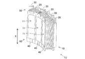
FIG. 1 is a perspective view schematically showing a part of the stator. FIG. 2 is a diagram schematically showing the configuration of the bobbin and the split core, where (a) is a perspective view of the first bobbin, (b) is a perspective view of the split core, and (c) is a perspective view of the second bobbin. It is. 3A and 3B are diagrams schematically illustrating the configuration of the bobbin unit, in which FIG. 3A is a perspective view of the first bobbin unit, FIG. 3B is an enlarged view of a portion A of FIG. Part B is an enlarged view, and (d) is a perspective view of the second bobbin unit.
本実施形態の3相回転電機は、ステータコア10が回転軸Xの周方向に分割されている分割コア11を有するステータ1と、ステータ1と同軸に対向して配される図示しないロータと、を備えており、集中巻き方式により巻線20が分割コア11に巻装されている。図1では、説明の便宜上、3個の分割コア11、11、11が図示されている。実際の3相回転電機は、3相を構成する3個の分割コア11、11、11を一単位として、分割コア11が回転軸Xの周方向に円環状に配されている。本明細書では、図1に示す一単位分の分割コア11から構成されるステータをステータユニット1Uという。
The three-phase rotating electrical machine according to the present embodiment includes a stator 1 having a
分割コア11は、電磁鋼板からなるコアシートを軸方向に複数枚積層して形成されている。図2(b)に示すように、分割コア11は、円周方向に延在するヨーク部12と、ヨーク部12の内周側側面から回転軸X方向に突出して磁極を形成するティース部13と、を有している。ティース部13の先端部には、図示しないロータの外周面と対向可能な周方向に幅広の対向部131が形成されている。
The
巻線20は、断面円形状の丸線が用いられ、導体表面がエナメル被覆などの絶縁層で保護されている。丸線以外にも断面多角形状の角線など、種々の断面形状の細線を用いることができる。細線を複数本並列に配列した並列細線を用いることもできる。 The winding 20 is a round wire having a circular cross section, and the conductor surface is protected by an insulating layer such as enamel coating. In addition to the round line, various cross-sectional thin lines such as a polygonal cross-sectional square line can be used. A parallel thin wire in which a plurality of thin wires are arranged in parallel can also be used.
分割コア11は、第1ボビン30及び第2ボビン40によって軸方向両端から狭持されている。第1ボビン30及び第2ボビン40は、樹脂などの絶縁材料からなり、射出成型によって形成されている。本明細書において、「ボビン」とは、ステータコア10と巻線20とを電気的に絶縁する絶縁部材をいい、インシュレータと呼称されることもある。図2(a)に示すように、第1ボビン30は、巻線20が巻回される胴部31と、胴部31の内周側側面に軸方向に延在する内周側鍔部32と、胴部31の外周側側面に軸方向に延在する外周側鍔部33と、を有している。内周側鍔部32及び外周側鍔部33は、胴部31と一体に形成されており、それぞれ対向している。第1ボビン30には、凹部が設けられており、軸方向からティース部13に被装可能になっている。以下、内周側鍔部32の周方向端部を単に第1ボビン30の内周側端部34、34という。また、外周側鍔部33の周方向端部を単に第1ボビン30の外周側端部35、35という。
The
同図(c)に示すように、第2ボビン40は、ティース部13を周方向から狭持可能なコア狭持部41と、コア狭持部41と軸方向に一体に形成されてティース部13を支持可能なコア支持部42と、を有している。コア狭持部41は、内周側端部が周方向に折り曲げられて内周側折曲部411、411が形成され、外周側端部は周方向に折り曲げられて外周側折曲部412、412が形成されている。内周側折曲部411、411は、分割コア11の対向部131と当接可能になっており、外周側折曲部412、412は、分割コア11のヨーク部12と当接可能になっている。コア支持部42は、周方向側端部が軸方向に延在して側面支持部421、421が形成されている。側面支持部421、421は、内周側折曲部411、411とそれぞれ接合されている。以下、側面支持部421、421の周方向端部を単に第2ボビン40の内周側端部43、43という。また、外周側折曲部412、412の周方向端部を単に第2ボビン40の外周側端部44、44という。
As shown in FIG. 5C, the
3個の分割コア11、11、11の軸方向一端側には、図3(a)に示すように、周方向に配される3つの第1ボビン30、30、30を一単位として第1ボビンユニット50が構成されている。第1ボビンユニット50は、中央に位置する第1ボビン30の内周側両端部34、34が、隣接する第1ボビン30の内周側端部34とそれぞれ屈曲可能に一体に形成されて第1屈曲部36、36になっている。中央に位置する第1ボビン30の外周側両端部35、35は、隣接する第1ボビン30の外周側端部35とそれぞれ当接可能になっている。同図(b)に示すように、第1屈曲部36は、外周方向に開口する薄肉の第1凹部361を有しており、周方向両端に位置する第1ボビン30、30は、第1屈曲部36、36を支点にしてそれぞれ内周側に回転可能になっている。同図(c)に示すように、周方向両端の内周側端部34、34は、周方向に開口する薄肉の第2凹部341をそれぞれ有している。
As shown in FIG. 3 (a), the three divided
3個の分割コア11、11、11の軸方向他端側には、同図(d)に示すように、周方向に配される3つの第2ボビン40、40、40を一単位として第2ボビンユニット60が構成されている。第2ボビンユニット60は、中央に位置する第2ボビン40の内周側両端部43、43が、隣接する第2ボビン40の内周側端部43とそれぞれ屈曲可能に一体に形成されて第2屈曲部45、45になっている。中央に位置する第2ボビン40の外周側両端部44、44は、隣接する第2ボビン40の外周側端部44とそれぞれ当接可能になっている。第2屈曲部45は、第1屈曲部36と同形状の外周方向に開口する薄肉の第3凹部を有しており、周方向両端に位置する第2ボビン40、40は、第2屈曲部45、45を支点にしてそれぞれ内周側に回転可能になっている。周方向両端の内周側端部43、43は、第2凹部341と同形状の周方向に開口する薄肉の第4凹部をそれぞれ有している。
On the other end side in the axial direction of the three divided
<3相回転電機の製造方法>
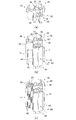
次に、既述の分割コア11、第1ボビンユニット50、第2ボビンユニット60及び巻線20を用いて、3相回転電機のステータ1を製造する方法を詳述する。本実施形態の3相回転電機の製造方法は、組立て工程、巻装工程及び封止工程を有しており、この順にステータ1の製造が行われる。図4は、ステータの組立て工程の一部を説明する図であり、(a)は第2ボビンユニットの斜視図、(b)は第2ボビンユニットに分割コアを装着した状態を示す斜視図である。図5は、ステータの組立て工程及び巻装工程を説明する図であり、(a)は第1ボビンユニットの斜視図、(b)は第1ボビンユニットを装着した状態を示す斜視図、(c)は1相分の巻線が巻装された状態を示す斜視図である。図6は、巻装後の状態を説明する図であり、(a)は斜視図、(b)は上面図、(c)は(b)のC部拡大図である。
<Method for manufacturing a three-phase rotating electrical machine>
Next, a method for manufacturing the stator 1 of the three-phase rotating electrical machine using the divided
(組立て工程)
組立て工程は、3個の分割コア11、11、11に第1ボビンユニット50及び第2ボビンユニット60を軸方向両端からそれぞれ装着する工程である。まず、図4(a)に示すように、第2ボビンユニット60の周方向両端に位置する第2ボビン40、40を第2屈曲部45、45を支点にして、それぞれ内周側に回転させる。そして、周方向両端の内周側端部43、43同士を当接させる。この状態で同図(b)に示すように、第2ボビンユニット60に3個の分割コア11、11、11を装着する。
(Assembly process)
The assembling process is a process of mounting the
次に、図5(a)に示すように、第1ボビンユニット50の周方向両端に位置する第1ボビン30、30を第1屈曲部36、36を支点にして、それぞれ内周側に回転させる。そして、周方向両端の内周側端部34、34同士を当接させる。この状態で上述の3個の分割コア11、11、11に第1ボビンユニット50を装着する。このとき、第1ボビンユニット50の内周側端部34、34の当接部37と第2ボビンユニット60の内周側端部43、43の当接部46とが同一直線上に揃うようにする。同図(b)は、3個の分割コア11、11、11に第1ボビンユニット50及び第2ボビンユニット60が軸方向両端からそれぞれ装着された状態を示している。
Next, as shown in FIG. 5 (a), the
本実施形態では、第2ボビンユニット60に3個の分割コア11、11、11を装着した後に第1ボビンユニット50を装着しているが、第1ボビンユニット50に3個の分割コア11、11、11を装着した後に第2ボビンユニット60を装着しても良い。また、3個の分割コア11、11、11を第1ボビンユニット50及び第2ボビンユニット60で狭持した後に、内周側端部34、34同士及び内周側端部43、43同士をそれぞれ当接させて同図(b)の状態にすることもできる。
In the present embodiment, the
(巻装工程)
巻装工程は、図5(b)に示すように、3個の分割コア11、11、11に装着された第1ボビンユニット50の内周側側面321、321、321を軸方向視においてΔ形状にして巻線20を巻装する工程である。同図(c)に示すように、1相分の巻回し後に次の相の巻回しを行い3相分の巻線20を巻装しても良く、2相分又は3相分を同時に巻装することもできる。図6は、3相分の巻線20が巻装された状態を示している。
(Winding process)
In the winding step, as shown in FIG. 5B, the inner peripheral side surfaces 321, 321 and 321 of the
同図(b)及び(c)に示すように、本工程は、第1ボビンユニット50の内周側側面321、321、321を軸方向視においてΔ形状にして巻装することに特徴がある。第1屈曲部36、36及び当接部37は、Δ形状の頂点になる。Δ形状にして巻装することにより、巻装していない他の第1ボビン30、30が干渉せず、作業効率が向上する。また、Δ形状にして巻装することにより、2相分又は3相分の巻線20を同時に巻装することもできる。なお、内周側側面321は周方向に湾曲しており、正確にはΔ形状とは言えないが、本明細書では、説明の便宜上、Δ形状と称する。
As shown in FIGS. 5B and 5C, this step is characterized in that the inner peripheral side surfaces 321, 321, 321 of the
第1ボビンユニット50の内周側側面321、321、321を軸方向視においてΔ形状にすると、それと対をなす第2ボビンユニット60の内周側側面もΔ形状になる。したがって、巻装工程は、第2ボビンユニット60の内周側側面を軸方向視においてΔ形状にして巻線20を巻装する工程でもある。この場合の内周側側面は、内周側折曲部411、411及び側面支持部421、421によって周方向に形成される面をいう。
When the inner peripheral side surfaces 321, 321, 321 of the
(封止工程)
封止工程は、巻線20が巻装された第1ボビンユニット50及び第2ボビンユニット60を周方向に沿わせて、隣接する第1ボビンユニット50同士及び第2ボビンユニット60同士を内周側端部でそれぞれシールする工程である。図6(b)、(c)に示すように、3相分の巻線20が巻装された状態において、当接部37に隣接する第1ボビン30、30を第1屈曲部36、36を支点にして、第1屈曲部36の開口部を狭める方向にそれぞれ回転させる。内周側側面321、321、321が同一円周上に配されるまで回転させると、図1に示すステータユニット1Uの状態になる。なお、既述のとおり、第2ボビンユニット60の当接部46に隣接する第2ボビン40、40を回転させても同じことである。この場合は、第2ボビン40、40を第2屈曲部45の開口部を狭める方向に回転させる。
(Sealing process)
In the sealing step, the
図7は、ステータの一部を模式的に示す上面図である。同図は、2つのステータユニット1U、1Uが周方向に配されている状態を示している。周方向に隣接する2つの第1ボビンユニット50、50は、内周側端部34、34でシール部材70によってシールされている。第1ボビンユニット50と同様に、周方向に隣接する2つの第2ボビンユニット60、60は、内周側端部43、43でシール部材70によってシールされている。シール部材70は、ステータ1をステータハウジングに焼きばめ又は圧入固定するときに、第1ボビンユニット50の内周側端部34、34及び第2ボビンユニット60の内周側端部43、43によってそれぞれ挟み込まれる。シール部材70は、内周側端部34及び内周側端部43の形状に合わせた形状にする。本実施形態では、内周側端部34、34同士又は内周側端部43、43同士をそれぞれ当接させると、軸方向視の断面形状が円形となるので、環状のシール部材を用いている。シール部材70は、例えば、ゴムなどの絶縁材を用いることができる。内周側端部34及び内周側端部43は、同一形状であり軸線方向に連通している。そのため、シール部材70は、第1ボビンユニット50及び第2ボビンユニット60の軸線方向に亘って一体に形成されているが、別体に形成することもできる。
FIG. 7 is a top view schematically showing a part of the stator. The figure shows a state in which two
本実施形態では、3相の巻線20、20間に軸線方向に延びる冷却路71が形成されている。冷却路71は、3相の巻線20、20間に軸線方向に設けられているので、3相の巻線20、20間に冷却媒体を流通させて、ステータ1のうち最も発熱量が多い巻線20を直接冷却することができる。また、第1ボビンユニット50の周方向両端の内周側端部34、34及び第2ボビンユニット60の周方向両端の内周側端部43、43は、シール部材70によってシールされているので、巻線20から抜熱した冷却媒体がロータ側へ流出することを防止できる。そのため、冷却媒体によるロータへの伝熱及びロータの摩擦損失を低減することができる。
In the present embodiment, a cooling
第1ボビンユニット50は、周方向に隣接する3つの第1ボビン30、30、30が一体に形成されているので、中央に位置する第1ボビン30と隣接する第1ボビン30、30との内周側端部(第1屈曲部36、36)にシール部材70を設ける必要がない。よって、3つの第1ボビン30、30、30の内周側端部をそれぞれシール部材70によってシールする場合と比べて、シール部材70の使用量を1/3に低減することができる。また、第1屈曲部36、36は軸方向に連通しているので、冷却媒体の流路となり、冷却媒体の流路が拡大されて冷却性能が向上する。さらに、3つの第1ボビン30、30、30が一体形成されているので、ステータ1の部品点数を低減させることができる。よって、部品点数の低減による信頼性の向上及びコストダウンを図ることができる。以上のことは、第2ボビンユニット60についても同様に言える。
In the
(変形形態)
本変形形態では、第1ボビンユニット50及び第2ボビンユニット60の代わりに第1ボビンユニット51及び第2ボビンユニット61を用いる。第1ボビンユニット51は、周方向に配される3つの第1ボビン30、30、30を一単位として、各第1ボビン30の内周側両端部34、34が隣接する第1ボビン30の内周側端部34と屈曲可能に一体に形成され、内周側側面321、321、321が軸方向視においてΔ形状を呈している。屈曲部は、既述の第1屈曲部36と同形状であり、第1屈曲部36、36、36がΔ形状の頂点になる。同様に、第2ボビンユニット61は、周方向に配される3つの第2ボビン40、40、40を一単位として、各第2ボビン40の内周側両端部43、43が隣接する第2ボビン40の内周側端部43と屈曲可能に一体に形成され、内周側側面が軸方向視においてΔ形状を呈している。屈曲部は、既述の第2屈曲部45と同形状であり、第2屈曲部45、45、45がΔ形状の頂点になる。第1ボビンユニット51及び第2ボビンユニット61は、第1ボビンユニット50及び第2ボビンユニット60と同様に、3個の分割コア11、11、11に軸方向両端から装着可能になっている。
(Deformation)
In this modification, the first bobbin unit 51 and the second bobbin unit 61 are used instead of the
組立て工程は、3個の分割コア11、11、11に第1ボビンユニット51及び第2ボビンユニット61を軸方向両端から装着する工程である。巻装工程は、3個の分割コア11、11、11に装着された第1ボビンユニット51及び第2ボビンユニット61に巻線20を巻装する工程である。既述の実施形態と同様、装着及び巻装の順序は問わない。
The assembling process is a process of mounting the first bobbin unit 51 and the second bobbin unit 61 on the three divided
本変形形態では、巻線20の巻装後にΔ形状の頂点のひとつを切開する切開工程を有する。切開工程では、第1ボビンユニット51のΔ形状の頂点である第1屈曲部36、36、36のひとつを軸方向に切開する。同様に、第2ボビンユニット61のΔ形状の頂点である第2屈曲部45、45、45のひとつを軸方向に切開する。これにより、第1ボビンユニット51及び第2ボビンユニット61を展開して周方向に沿わせることができる。
In this modified embodiment, an incision step of incising one of the vertices of the Δ shape after the winding 20 is wound is provided. In the incision step, one of the first
本変形形態では、内周側側面が軸方向視においてΔ形状を呈する第1ボビンユニット51及び第2ボビンユニット61を用いて巻線20の巻回しを行い、巻装後にΔ形状の頂点のひとつを切開するので、巻装前に周方向両端の内周側端部34、34同士及び周方向両端の内周側端部43、43同士をそれぞれ当接させてΔ形状にする必要がなく、作業効率が向上する。また、3個の分割コア11、11、11、第1ボビンユニット51及び第2ボビンユニット61の組立ても容易である。
In this modified embodiment, the winding 20 is wound using the first bobbin unit 51 and the second bobbin unit 61 whose inner peripheral side faces have a Δ shape when viewed in the axial direction, and one of the apexes of the Δ shape after winding. Therefore, before winding, it is not necessary to contact the inner peripheral side ends 34, 34 at both ends in the circumferential direction and the inner peripheral side ends 43, 43 at both ends in the circumferential direction to make a Δ shape, respectively. Work efficiency is improved. Further, it is easy to assemble the three divided
封止工程は、Δ形状の頂点のひとつが切開された第1ボビンユニット51及び第2ボビンユニット61を周方向に沿わせて、隣接する第1ボビンユニット51同士及び第2ボビンユニット61同士を内周側端部でそれぞれシールする工程である。シール箇所及びシール部材は、既述の実施形態と同様である。 In the sealing step, the first bobbin unit 51 and the second bobbin unit 61 adjacent to each other are arranged along the circumferential direction of the first bobbin unit 51 and the second bobbin unit 61 in which one of the Δ-shaped apexes is cut. This is a step of sealing at the inner peripheral end. The seal location and the seal member are the same as in the above-described embodiment.
<3相回転電機>
図8は、3相電動機の一例を示す断面図である。図8に示す3相電動機は、ハイブリッド車両の車輪駆動用の3相同期モータであり、既述のステータ1及びロータ2をモータハウジング3に内蔵した状態で、モータカバー4(本発明の「冷却媒体供給カバー」に相当)により封止されている。3相電動機の一端側は、図示しない車両のトランスミッションに接続され、3相電動機の他端側は、図示しないエンジンの出力軸に係脱可能に接続されている。
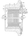
<3-phase rotating electrical machine>
FIG. 8 is a cross-sectional view showing an example of a three-phase motor. The three-phase motor shown in FIG. 8 is a three-phase synchronous motor for driving wheels of a hybrid vehicle. Corresponding to “medium supply cover”). One end side of the three-phase motor is connected to a transmission of a vehicle (not shown), and the other end side of the three-phase motor is detachably connected to an output shaft of an engine (not shown).
ステータ1は、ステータハウジング100を介してボルト300でモータハウジング3に固定されている。ステータ1は、既述のステータユニット1Uが回転軸Xの周方向に円環状に配されており、隣接するステータユニット1Uは、内周側端部同士がシール部材70によってシールされている。ステータ1は、同相の巻線20が相毎にそれぞれ直列接続されており、直列接続された巻線20の一端側はY結線されている。直列接続された巻線20の他端側は、図示しないインバータを介して車両バッテリに接続されている。車両バッテリの電力は、インバータによって3相交流に変換された後、3相電動機に供給されてロータ2を駆動することができる。3相電動機によって発電された電力は、インバータを介して車両バッテリに充電される。なお、同図では、冷却媒体が3相の巻線20間を軸線方向(同図に示す矢印D方向)に流れることを明示するために、ステータ1は、模式的に示されている。
The stator 1 is fixed to the
ステータ1の径方向内周側には、ステータ1と所定のギャップを保持して対向するロータ2が配されている。ロータ2は、複数の積層鋼板から形成されており、ロータ2の円周上には、複数の界磁極用マグネットが設けられている。ロータ2は、シャフト5と同軸に回転可能に固定されており、シャフト5は、軸受500、500を介してモータハウジング3及びモータカバー4に支承されている。モータカバー4は、ボルト300でモータハウジング3に固定されている。図示しない車両バッテリからインバータを介して、巻線20に対して三相の交流電流が供給されることにより、ステータ1において回転磁界が発生し、回転磁界に起因する吸引力又は反発力によって、ステータ1に対してロータ2が回転する。
On the radially inner peripheral side of the stator 1, a
モータカバー4には、冷却媒体を吐出可能な配管400(本発明の「配管」に相当)が軸方向Xに突出して形成されており、配管400は、ポンプ6の吐出口600に接続されている。ポンプ6の吸入口601は、配管401によりリザーバ7に接続されている。リザーバ7には、ステータ1の巻線20を冷却可能な冷却媒体が貯蔵されている。冷却媒体は、例えば、油や空気、窒素などの冷却剤を用いることができる。なお、同図では、ポンプ6及びリザーバ7は、3相電動機と別体に記載されているが、実際には、ポンプ6は3相電動機と一体化されており、リザーバ7はモータハウジング3内に形成されている。
The
第2ボビンユニット60の軸方向端部は、ゴム製のオーリング8、8を介してモータカバー4に接続さており、ポンプ6から吐出された冷却媒体がロータ2側やステータハウジング100側に漏れ出さないように接続部分が密閉されている。第2ボビンユニット60の軸方向端部は、本発明の「内周側鍔部および外周側鍔部」に相当し、オーリング8、8は、本発明の「シール部材」に相当する。また、同図に示すように、モータカバー4のうちステータ1側に突出している部分は、本発明の「突起部」に相当する。ポンプ6から吐出された冷却媒体は、配管400に導入されて配管400の開口部402(本発明の「開口部」に相当)からステータ1の巻線20に向けて吐出される。冷却媒体は、3相の巻線20間を矢印D方向に流れて、図示しない配管を経由してリザーバ7に排出される。冷却媒体は、3相の巻線20間を通過するときに3相電動機の駆動によって巻線20に生じた熱を抜熱する。
The axial end of the
本実施形態の3相電動機は、隣接するステータユニット1Uの内周側端部同士がシール部材70によってシールされているので、3相の巻線20間を矢印D方向に流れる冷却媒体がロータ2側に流出することを防止できる。そのため、冷却媒体によるロータ2への伝熱及びロータ2の摩擦損失を低減することができる。なお、ロータ2側への冷却媒体の流出をより抑制するため、冷却媒体の排出側にも、モータカバー4と同様のカバーを配置してもよい。
In the three-phase motor of the present embodiment, the inner peripheral side ends of the
(2)第2実施形態
本実施形態は、第1実施形態と比べて、3相の巻線20間に形成される冷却路71の形態が異なる。具体的には、冷却路71に供給される冷却媒体の供給側から排出側にかけて、冷却路71における巻線20の相間距離が徐々に短くなっており、冷却路71は、冷却媒体の供給側と比べて、冷却媒体の排出側の流路が狭くなっている。第1実施形態と共通する箇所には、共通の符号を付して対応させることにより、重複する説明を省略する。
(2) 2nd Embodiment This embodiment differs in the form of the cooling
図9は、冷却路を説明する径方向視断面図である。同図は、2相分の分割コア11、11を軸線方向に切断して、巻線20、20間に形成される冷却路71を模式的に示したものである。同図では、冷却媒体の供給側を矢印D1方向で示し、冷却媒体の排出側を矢印D2方向で示している。よって、冷却媒体は、矢印D1方向側から矢印D2方向側(つまり矢印D方向)に供給される。また、巻線20、20の熱交換面と冷却媒体との境界を境界層BL1、BL2とする。なお、説明の便宜上、巻線20、20は、それぞれ第1ボビン30および第2ボビン40に3重に巻回されているものとし、巻回し状態を3重の円環で示している。
FIG. 9 is a radial sectional view for explaining the cooling path. The figure schematically shows a
同図に示すように、第1ボビン30および第2ボビン40において、巻線20が巻回される部分の肉厚は、冷却媒体の供給側(矢印D1方向側)が最も薄肉になっており、冷却媒体の排出側(矢印D2方向側)にかけて徐々に厚肉になっている。具体的には、第2ボビン40のコア狭持部41において、巻線20が巻回される部分の肉厚は、コア支持部42と接続される部分が最も薄肉になっており、冷却媒体の排出側(矢印D2方向側)にかけて徐々に厚肉になっている。軸線方向において、コア狭持部41の肉厚が最も薄肉の部分(コア支持部42と接続される部分)の周方向長を最小周方向長L1とする。
As shown in the figure, in the
第1ボビン30の胴部31において、巻線20が巻回される部分の肉厚は、コア狭持部41と接続される部分が最も薄肉になっており、冷却媒体の排出側(矢印D2方向側)にかけて徐々に厚肉になっている。軸線方向において、胴部31の肉厚が最も厚肉の部分の周方向長を最大周方向長L2とする。このように、第1ボビン30および第2ボビン40において、巻線20が巻回される部分の肉厚が徐変されているので、最大周方向長L2は、最小周方向長L1と比べて長くなっている。よって、第1ボビン30および第2ボビン40に巻線20を巻装すると、冷却媒体の供給側(矢印D1方向側)の冷却路71における巻線20、20の相間距離G1は、冷却媒体の排出側(矢印D2方向側)の冷却路71における巻線20、20の相間距離G2と比べて大きくなる。
In the
一般的に、「抜熱量は、熱交換面積と温度差に比例し、(理論上)流速の平方根に比例する。」ことが知られている。冷却媒体の供給側(矢印D1方向側)では、冷却媒体の排出側(矢印D2方向側)と比べて、巻線20、20と冷却媒体との温度差が大きく冷却効率は高い。そのため、冷却媒体の流速を排出側(矢印D2方向側)と比べて低速にしても、十分な抜熱量を確保することができる。一方、冷却媒体の排出側(矢印D2方向側)では、巻線20、20からの抜熱にしたがって冷却媒体の温度が上昇して、巻線20、20と冷却媒体との温度差は小さくなり、冷却効率は低下する。そのため、冷却媒体の流速を供給側(矢印D1方向側)と比べて高速にして、必要な抜熱量を確保する必要がある。
It is generally known that “the amount of heat removal is proportional to the heat exchange area and the temperature difference, and (theoretically) proportional to the square root of the flow velocity”. On the cooling medium supply side (arrow D1 direction side), the temperature difference between the
本実施形態では、冷却路71に供給される冷却媒体の供給側(矢印D1方向側)から排出側(矢印D2方向側)にかけて、冷却路71における巻線20、20の相間距離G1、G2が徐々に短くなっているので、冷却媒体の供給側(矢印D1方向側)の流速と比べて、冷却媒体の排出側(矢印D2方向側)の流速を高速にすることができる。したがって、冷却媒体の供給側(矢印D1方向側)から排出側(矢印D2方向側)にかけて、冷却媒体の流速を徐々に速くして、巻線20、20からの抜熱量を均一化することができる。
In the present embodiment, the interphase distances G1 and G2 of the
なお、冷却路71の流路抵抗や冷却媒体の粘性等により、境界層BL1、BL2の厚さが変化し、必要な冷却媒体の流速も変化する。そのため、冷却路71の流路抵抗や冷却媒体の粘性等を考慮して、冷却路71における巻線20、20の相間距離G1、G2を予め導出しておくと好適である。冷却路71における巻線20、20の相間距離G1、G2の導出方法は限定されない。例えば、公知の対流伝熱シミュレーション、実機による測定等によって、導出することができる。
Note that the thicknesses of the boundary layers BL1 and BL2 change due to the flow resistance of the
また、冷却路71における巻線20、20の相間距離G1、G2を可変する方法は、限定されない。例えば、冷却媒体の供給側(矢印D1方向側)と排出側(矢印D2方向側)とにおいて、巻線20の巻回し方法を変更することによって、冷却路71における巻線20、20の相間距離G1、G2を可変することもできる。また、巻線20の巻回し方法の変更と併せて、第1ボビン30および第2ボビン40において、巻線20が巻回される部分の肉厚を徐変することもできる。
Further, the method for changing the interphase distances G1 and G2 of the
(3)参考形態
本参考形態は、第1実施形態および第2実施形態と比べて、第1ボビンユニット50および第2ボビンユニット60が構成されていない点で異なる。そのため、隣接する第1ボビン30間は、第1ボビン30の内周側端部34でそれぞれシールされており、隣接する第2ボビン40間は、第2ボビン40の内周側端部43でそれぞれシールされている。第1実施形態および第2実施形態と共通する箇所には、共通の符号を付して対応させることにより、重複する説明を省略する。
(3) Reference Form This reference form differs from the first embodiment and the second embodiment in that the
図10は、ステータの一部を模式的に示す上面図である。同図は、2つのステータユニット1U、1Uに相当する6つの第1ボビン30が周方向に配されている状態を示している。周方向に隣接する第1ボビン30間は、第1ボビン30の内周側端部34でシール部材70によってそれぞれシールされている。同様に、周方向に隣接する第2ボビン40間は、第2ボビン40の内周側端部43でシール部材70によってそれぞれシールされている。シール部材70は、ステータ1をステータハウジングに焼きばめ又は圧入固定する際に、第1ボビン30の内周側端部34、34および第2ボビン40の内周側端部43、43によってそれぞれ挟み込まれる。シール部材70の材質および形状等は、第1実施形態および第2実施形態と同様である。
FIG. 10 is a top view schematically showing a part of the stator. The figure shows a state in which six
本参考形態では、第1実施形態および第2実施形態と同様に、3相の巻線20、20間に軸線方向に延びる冷却路71が形成されている。そのため、3相の巻線20、20間に冷却媒体を流通させて、ステータ1のうち最も発熱量が多い巻線20を直接冷却することができる。また、隣接する第1ボビン30間は、第1ボビン30の内周側端部34でシールされており、隣接する第2ボビン40間は、第2ボビン40の内周側端部43でシールされている。そのため、巻線20から抜熱した冷却媒体がロータ側へ流出することを防止でき、冷却媒体によるロータへの伝熱およびロータの摩擦損失を低減することができる。
In this preferred embodiment, similarly to the first embodiment and the second embodiment, the
本参考形態における3相回転電機の製造方法は、組立て工程、巻装工程および封止工程を有しており、この順にステータ1の製造が行われる。組立て工程では、1個の分割コア11に第1ボビン30および第2ボビン40を軸方向両端から装着する。巻装工程では、分割コア11に装着された第1ボビン30および第2ボビン40に巻線20を巻装する。封止工程では、巻線20が巻装された第1ボビン30および第2ボビン40を周方向に沿わせて、隣接する第1ボビン30同士を内周側端部34でシールして、隣接する第2ボビン40同士を内周側端部43でシールする。なお、巻装工程では、3つの第1ボビン30、30、30の内周側側面321、321、321が軸方向視においてΔ形状になるように第1ボビン30、30、30を固定して、巻線20を巻装することもできる。この場合、第2ボビン40についても同様である。
Method for producing a 3-phase rotary electric machine according to the present reference embodiment, the assembly process has a winding step and the sealing step, the production of the stator 1 are performed in this order. In the assembly process, the
(4)その他
本発明は上記し且つ図面に示した実施形態のみに限定されるものではなく、要旨を逸脱しない範囲内で適宜変更して実施可能である。
(4) Others The present invention is not limited to the embodiment described above and shown in the drawings, and can be implemented with appropriate modifications within a range not departing from the gist .
ロータは、永久磁石を用いたものであっても、巻線を用いたものであっても良い。永久磁石形のロータは、巻線の発熱による温度上昇が生じないので、ロータの温度保護が不要となる。また、3相回転電機は、直流機、同期機又は誘導機のいずれであっても良い。直流励磁の場合は、励磁電流により磁力調整が可能であり、交流励磁の場合は、周波数により速度制御をすることができる。誘導機の場合は、巻線に接続する抵抗値により始動特性を変えることもできる。 The rotor may be a permanent magnet or a winding. In the permanent magnet type rotor, the temperature rise due to the heat generation of the winding does not occur, so that it is not necessary to protect the rotor temperature. Further, the three-phase rotating electric machine may be a DC machine, a synchronous machine or an induction machine. In the case of DC excitation, the magnetic force can be adjusted by the excitation current, and in the case of AC excitation, the speed can be controlled by the frequency. In the case of an induction machine, the starting characteristics can be changed by the resistance value connected to the winding.
ロータは、ステータの内周側にロータを配置するインナーロータであっても、ステータの外周側にロータを配置するアウターロータであっても良い。インナーロータは慣性モーメントが小さく、3相回転電機の速度制御が容易である。アウターロータは、逆に慣性モーメントが大きく、駆動トルクも大きくできるので、定速度運転に優れる。 The rotor may be an inner rotor in which the rotor is disposed on the inner peripheral side of the stator or an outer rotor in which the rotor is disposed on the outer peripheral side of the stator. The inner rotor has a small moment of inertia, and speed control of the three-phase rotating electrical machine is easy. The outer rotor, on the other hand, has a large moment of inertia and a large driving torque, and is therefore excellent in constant speed operation.
1:ステータ
2:ロータ
10:ステータコア 11:分割コア
20:巻線
30:第1ボビン 40:第2ボビン
50:第1ボビンユニット 60:第2ボビンユニット
1: Stator 2: Rotor 10: Stator core 11: Split core 20: Winding 30: First bobbin 40: Second bobbin 50: First bobbin unit 60: Second bobbin unit
Claims (6)
前記ボビンは、前記周方向に配される3つのボビンを一単位として、中央に位置するボビンの内周側両端部が隣接するボビンの内周側端部と屈曲可能に一体に形成され、3個の前記分割コアに軸方向両端から装着可能に軸方向で分割されたボビンユニットとして構成され、
前記3個の分割コアには、前記ボビンユニットが軸方向両端から装着されており、前記ボビンユニットは、隣接する前記一単位毎の前記ボビンユニット間において内周側端部でシールするようシール部材が配置されており、3相の巻線間に軸線方向に延びる冷却路が形成されていることを特徴とする3相回転電機。 A stator having a split core in which the stator core is split in the circumferential direction of the rotating shaft, and a rotor arranged coaxially with the stator, and concentrated on the split core on which a bobbin made of an insulating material is mounted In the three-phase rotating electrical machine in which the winding is wound by the winding method,
The bobbin has three bobbins arranged in the circumferential direction as a unit, and both end portions on the inner peripheral side of the bobbin located in the center are integrally formed with an inner peripheral side end portion of the adjacent bobbin so as to be bendable. It is configured as a bobbin unit that is divided in the axial direction so that it can be attached to both of the divided cores from both axial ends,
The bobbin unit is attached to the three divided cores from both ends in the axial direction, and the bobbin unit is sealed at an inner peripheral end between the adjacent bobbin units for each unit. And a cooling path extending in the axial direction is formed between the three-phase windings.
Priority Applications (3)
| Application Number | Priority Date | Filing Date | Title |
|---|---|---|---|
| JP2012152077A JP6079012B2 (en) | 2011-09-09 | 2012-07-06 | 3-phase rotating electric machine |
| US13/607,141 US8853910B2 (en) | 2011-09-09 | 2012-09-07 | Three-phase rotary electrical machine and manufacturing method thereof |
| EP12183440.2A EP2568574B1 (en) | 2011-09-09 | 2012-09-07 | Three-phase rotary electrical machine and manufacturing method thereof |
Applications Claiming Priority (3)
| Application Number | Priority Date | Filing Date | Title |
|---|---|---|---|
| JP2011196931 | 2011-09-09 | ||
| JP2011196931 | 2011-09-09 | ||
| JP2012152077A JP6079012B2 (en) | 2011-09-09 | 2012-07-06 | 3-phase rotating electric machine |
Publications (2)
| Publication Number | Publication Date |
|---|---|
| JP2013070595A JP2013070595A (en) | 2013-04-18 |
| JP6079012B2 true JP6079012B2 (en) | 2017-02-15 |
Family
ID=46851838
Family Applications (1)
| Application Number | Title | Priority Date | Filing Date |
|---|---|---|---|
| JP2012152077A Expired - Fee Related JP6079012B2 (en) | 2011-09-09 | 2012-07-06 | 3-phase rotating electric machine |
Country Status (3)
| Country | Link |
|---|---|
| US (1) | US8853910B2 (en) |
| EP (1) | EP2568574B1 (en) |
| JP (1) | JP6079012B2 (en) |
Families Citing this family (15)
| Publication number | Priority date | Publication date | Assignee | Title |
|---|---|---|---|---|
| KR101317892B1 (en) * | 2011-01-24 | 2013-10-16 | 주식회사 아모텍 | Amorphous Stator and Producing Method thereof |
| CN104079086A (en) * | 2013-03-29 | 2014-10-01 | 珠海格力节能环保制冷技术研究中心有限公司 | Stator, motor with stator and compressor |
| GB2525157B (en) * | 2014-02-18 | 2016-08-24 | Yasa Motors Ltd | Machine cooling systems |
| JP2015162975A (en) * | 2014-02-27 | 2015-09-07 | シンフォニアテクノロジー株式会社 | Stator and inner rotor type motor |
| GB2533154B (en) * | 2014-12-12 | 2017-06-07 | Protean Electric Ltd | A coil winding arrangement |
| KR102408250B1 (en) * | 2015-07-21 | 2022-06-13 | 엘지이노텍 주식회사 | Rotor and Motor having the same |
| DE102016209752A1 (en) * | 2016-06-03 | 2017-12-07 | Continental Automotive Gmbh | Cooling an electric machine |
| US10819190B2 (en) * | 2016-08-18 | 2020-10-27 | Nidec Corporation | Motor |
| CN107786021B (en) * | 2016-08-29 | 2019-10-11 | 光宝电子(广州)有限公司 | Insulating sleeve with around wire work |
| EP3316454A1 (en) * | 2016-10-25 | 2018-05-02 | HILTI Aktiengesellschaft | Roll support and stator |
| DE102017102495A1 (en) * | 2017-02-08 | 2018-08-09 | Nidec Corporation | Stator for an electric motor |
| CN111628591A (en) * | 2019-02-28 | 2020-09-04 | 株式会社村田制作所 | Stator, stator assembly and converter of electric energy and mechanical energy |
| KR20230023836A (en) * | 2021-08-09 | 2023-02-20 | 주식회사 아모텍 | Stator Having Busbar Structure, Motor for Driving Propeller Using the Same and Method for Manufacturing the Stator |
| US11837917B2 (en) | 2022-01-28 | 2023-12-05 | Ge Aviation Systems Llc | Method and apparatus for cooling a rotor assembly |
| DE102022203436A1 (en) * | 2022-04-06 | 2023-10-12 | Brose Fahrzeugteile SE & Co. Kommanditgesellschaft, Würzburg | Stator and electric motor with such a stator |
Family Cites Families (23)
| Publication number | Priority date | Publication date | Assignee | Title |
|---|---|---|---|---|
| JP3017085B2 (en) * | 1995-11-02 | 2000-03-06 | 三菱電機株式会社 | Rotating electric machine and method of manufacturing the same |
| US6259347B1 (en) * | 1997-09-30 | 2001-07-10 | The United States Of America As Represented By The Secretary Of The Navy | Electrical power cooling technique |
| EP1168571A3 (en) | 2000-05-30 | 2003-12-17 | BAE SYSTEMS Controls, Inc. | Rotating machine having hollow stator field windings for coolant flow therein |
| JP3603784B2 (en) * | 2000-12-14 | 2004-12-22 | 日産自動車株式会社 | Rotating electric machine |
| JP3624825B2 (en) * | 2000-12-14 | 2005-03-02 | 日産自動車株式会社 | Rotating electric machine and method of manufacturing rotating electric machine |
| US6870292B2 (en) * | 2001-11-28 | 2005-03-22 | Nissan Motor Co., Ltd. | Stator for motor |
| US6608420B2 (en) * | 2002-01-03 | 2003-08-19 | Hsieh Hsin-Mao | Stator of an alternating current motor |
| JP3896883B2 (en) * | 2002-03-28 | 2007-03-22 | 日産自動車株式会社 | Rotating electric machine |
| US20050057106A1 (en) * | 2002-12-10 | 2005-03-17 | Ballard Power Systems Corporation | Methods and systems for electric machines having windings |
| JP3791492B2 (en) * | 2002-12-25 | 2006-06-28 | 株式会社日立製作所 | Rotating electric machine, electric vehicle, and resin insert molding method |
| JP4444639B2 (en) * | 2003-05-08 | 2010-03-31 | アスモ株式会社 | Stator for rotating electrical machine and method for manufacturing the same |
| EP1499000B1 (en) * | 2003-07-12 | 2006-04-26 | Grundfos a/s | Segmented stator |
| JP4410730B2 (en) * | 2005-06-29 | 2010-02-03 | 三菱電機株式会社 | Rotating electric machine stator, rotating electric machine, and method of manufacturing rotating electric machine stator |
| WO2008027535A2 (en) * | 2006-09-01 | 2008-03-06 | Sears David B | Insulator for stator assembly of brushless dc motor |
| KR101185353B1 (en) * | 2006-09-21 | 2012-09-21 | 엘지전자 주식회사 | Stator for electric motor and manufacturing method thereof |
| JP4661849B2 (en) | 2007-09-27 | 2011-03-30 | トヨタ自動車株式会社 | Stator structure |
| JP4880559B2 (en) * | 2007-09-28 | 2012-02-22 | 本田技研工業株式会社 | Cooling structure in rotating electrical machines |
| JP5021443B2 (en) * | 2007-12-14 | 2012-09-05 | 日立オートモティブシステムズ株式会社 | Rotating electric machine |
| JP2009153287A (en) * | 2007-12-20 | 2009-07-09 | Sumitomo Electric Ind Ltd | Molded coil for split stator, and method of manufacturing molded coil for stator, and molding device for molding molded coil for stator |
| JP4670942B2 (en) * | 2008-11-21 | 2011-04-13 | トヨタ自動車株式会社 | Rotating electric machine |
| JP2010239776A (en) * | 2009-03-31 | 2010-10-21 | Mitsubishi Heavy Ind Ltd | Rotary electric machine |
| CN201450371U (en) * | 2009-04-29 | 2010-05-05 | 中山大洋电机股份有限公司 | Stator structure of three-phase motor |
| US20120126643A1 (en) * | 2010-11-19 | 2012-05-24 | Ping Zhong | Apparatuses useful for cooling windings of rotor assemblies |
-
2012
- 2012-07-06 JP JP2012152077A patent/JP6079012B2/en not_active Expired - Fee Related
- 2012-09-07 EP EP12183440.2A patent/EP2568574B1/en not_active Not-in-force
- 2012-09-07 US US13/607,141 patent/US8853910B2/en not_active Expired - Fee Related
Also Published As
| Publication number | Publication date |
|---|---|
| EP2568574A3 (en) | 2017-09-27 |
| US20130062972A1 (en) | 2013-03-14 |
| EP2568574A2 (en) | 2013-03-13 |
| US8853910B2 (en) | 2014-10-07 |
| EP2568574B1 (en) | 2019-04-24 |
| JP2013070595A (en) | 2013-04-18 |
Similar Documents
| Publication | Publication Date | Title |
|---|---|---|
| JP6079012B2 (en) | 3-phase rotating electric machine | |
| JP5772832B2 (en) | Rotating machine | |
| US10186916B2 (en) | Rotary machine and electric vehicle | |
| US9419481B2 (en) | Rotary electric machine | |
| JP6042976B2 (en) | Rotating electric machine | |
| JP4886624B2 (en) | Permanent magnet type rotating electrical machine and permanent magnet type rotating electrical machine system | |
| JP5288724B2 (en) | Rotating electric machine rotor and rotating electric machine | |
| JP6402257B2 (en) | Stator coil, stator provided with the same, and rotating electric machine provided with the same | |
| JP4998450B2 (en) | Stator manufacturing method | |
| JP6709712B2 (en) | Synchronous reluctance type rotating electric machine | |
| JP2014045630A (en) | Rotary electric machine | |
| JP2020120470A (en) | Rotary electric machine | |
| US20160226355A1 (en) | Magnetic inductor electric motor | |
| US11043867B2 (en) | Cooling of the end-windings of an electric generator | |
| JP6416655B2 (en) | Rotating electric machine stator | |
| JP5330860B2 (en) | Rotating electric machine | |
| JP2015027175A (en) | Rotating electrical machine and method of manufacturing rotating electrical machine | |
| JP5988840B2 (en) | Rotating electric machine stator | |
| JP2013192339A (en) | Induction motor | |
| JP2014100038A (en) | Stator of rotary electric machine | |
| JP6210160B2 (en) | Synchronous reluctance rotating electric machine | |
| JP2016034192A (en) | Stator and rotary electric machine | |
| WO2023106338A1 (en) | Motor | |
| JP4464812B2 (en) | Motor stator and motor stator winding fixing method | |
| JP2000078785A (en) | Permanent magnet type motor |
Legal Events
| Date | Code | Title | Description |
|---|---|---|---|
| A621 | Written request for application examination |
Free format text: JAPANESE INTERMEDIATE CODE: A621 Effective date: 20150610 |
|
| A977 | Report on retrieval |
Free format text: JAPANESE INTERMEDIATE CODE: A971007 Effective date: 20160518 |
|
| A131 | Notification of reasons for refusal |
Free format text: JAPANESE INTERMEDIATE CODE: A131 Effective date: 20160524 |
|
| A521 | Written amendment |
Free format text: JAPANESE INTERMEDIATE CODE: A523 Effective date: 20160715 |
|
| TRDD | Decision of grant or rejection written | ||
| A01 | Written decision to grant a patent or to grant a registration (utility model) |
Free format text: JAPANESE INTERMEDIATE CODE: A01 Effective date: 20161220 |
|
| A61 | First payment of annual fees (during grant procedure) |
Free format text: JAPANESE INTERMEDIATE CODE: A61 Effective date: 20170102 |
|
| R151 | Written notification of patent or utility model registration |
Ref document number: 6079012 Country of ref document: JP Free format text: JAPANESE INTERMEDIATE CODE: R151 |
|
| LAPS | Cancellation because of no payment of annual fees |