EP2574541A1 - Furling system of a front sail around a stay of a sailboat - Google Patents
Furling system of a front sail around a stay of a sailboat Download PDFInfo
- Publication number
- EP2574541A1 EP2574541A1 EP12185156A EP12185156A EP2574541A1 EP 2574541 A1 EP2574541 A1 EP 2574541A1 EP 12185156 A EP12185156 A EP 12185156A EP 12185156 A EP12185156 A EP 12185156A EP 2574541 A1 EP2574541 A1 EP 2574541A1
- Authority
- EP
- European Patent Office
- Prior art keywords
- outer ring
- winding system
- locking
- sail
- sailboat
- Prior art date
- Legal status (The legal status is an assumption and is not a legal conclusion. Google has not performed a legal analysis and makes no representation as to the accuracy of the status listed.)
- Withdrawn
Links
Images


Classifications
-
- B—PERFORMING OPERATIONS; TRANSPORTING
- B63—SHIPS OR OTHER WATERBORNE VESSELS; RELATED EQUIPMENT
- B63H—MARINE PROPULSION OR STEERING
- B63H9/00—Marine propulsion provided directly by wind power
- B63H9/04—Marine propulsion provided directly by wind power using sails or like wind-catching surfaces
- B63H9/08—Connections of sails to masts, spars, or the like
- B63H9/10—Running rigging, e.g. reefing equipment
- B63H9/1021—Reefing
- B63H9/1028—Reefing by furling around stays
Definitions
- the present invention relates to a system for winding a front sail around a stay supporting a mast of a sailboat, and more particularly a winding system of a forward sail directly around a sail. a support stay of a mast of a sailboat.
- the first and third elements are arranged to allow, in use, a rotation of the support stay about its axis so as to allow the winding of the forward sail directly. around the support stay which then forms a winding mandrel.
- a halyard of the sailboat circulating in a pulley fixed permanently at the top of the mast, to connect a first end of the halyard at the second mounting portion of the second element, to exert traction on a second end of the halyard so as to position the forward sail, and finally to block the second end of the halyard at the foot of the mast.
- the present invention aims to remedy these disadvantages.
- the technical problem underlying the invention is therefore to provide a winding system of a sail before which is simple and economical structure, and can be used on any type of sailboat.
- the winding system according to the invention can be used on a sailboat provided with a non-metallic support strut, and for example textile, without risk of premature wear of the latter. Since a textile support strut provides optimum torque transmission to the forward sail when wrapped around the support strut, regardless of the size of the forward sail and the support forest, the winding system according to the invention is therefore usable on sailboats of great heights.
- the halyard used to hoist the element on which is fixed the front sail can be disconnected from this element after locking it on the other element, and then used for other applications.
- the presence of the remote control means makes it possible to ensure that the front sail is balanced without having to climb to the top of the mast, which makes it possible to secure the user when the sail is lowered.
- the element adapted to be fixed on the upper part of the mast comprises a first fixing portion intended to be fixed on the upper part of the mast, and a second fixing portion on which is intended to be fixed the upper end of the mast.
- the strut, the second fixing portion being rotatably mounted relative to the first fixing portion so as to allow, in use, a rotation of the support strut about its axis.
- the second fixing portion is advantageously mounted free to rotate relative to the first fixing portion about an axis of rotation substantially parallel to the axis of the first fixing portion.
- the element adapted to be fixed on the upper corner of the forward sail comprises a first mounting portion on which is intended to be mounted the upper corner of the forward sail, and a second mounting portion on which is intended to be mounted a halyard of the sailboat.
- the element adapted to be fixed on the upper corner of the forward sail is adapted to be mounted on the support strut so as to allow movement of said element along the 'prop.
- the element adapted to be mounted movably on the strut defines a passage conduit for the passage of the strut.
- the second element comprises a tubular portion adapted to receive the first element in the locking position of the second element on the first element.
- the locking means comprise a plurality of balls each mounted in a through bore formed in the tubular portion of the second element, each ball being movable between a locking position in which it cooperates with the first element so as to lock the first and second elements one on the other, and an unlock position.
- each ball in the locking position protrudes inside the sleeve and each ball in the unlocked position does not protrude inside the sleeve.
- Each ball is advantageously displaceable radially between its locking and unlocking positions.
- the second element comprises an outer ring slidably mounted around the tubular portion of the second element substantially along the axis of the tubular portion between a first position in which the outer ring blocks each ball in its locking position, and a second position in which the outer ring allows a movement of each ball to its unlocked position.
- the outer ring is rotatably mounted relative to the tubular portion of the second element.
- the second element comprises an inner ring slidably mounted in the tubular portion of the second element substantially along the axis of the tubular portion between a first position in which the inner ring blocks each ball in its position. unlocking, and a second position in which the inner ring allows a movement of each ball to its locking position.
- the balls in the unlocking position are arranged to immobilize the outer ring in its second position, and the balls in the locking position are arranged to release the outer ring and allow movement of the outer ring to its first position.
- the first element comprises an actuating portion arranged to cooperate with the inner ring and to displace this last to its second position when the tubular portion of the second element accommodates the first element.
- the outer ring comprises a first portion having a first inner diameter and a second portion having a second inner diameter greater than the first diameter, the first portion being arranged to cooperate with the balls and immobilize the latter. in their locking position when the outer ring is in its first position, the second portion being arranged to allow movement of the balls to their unlocking position when the outer ring is in its second position.
- the outer ring has an inclined ramp formed on the inner surface of the outer ring and arranged to bias the balls towards their locking position during movement of the outer ring to its first position.
- the inclined ramp is preferably formed between the first and second portions of the outer ring.
- the second element comprises first return means arranged to bias the outer ring towards its first position.
- the second element comprises second return means arranged to bias the inner ring towards its first position.
- the first element comprises an annular groove adapted to receive the balls in the locking position of the second element on the first element.
- control means comprise a traction member, such as a rope, cable or the like, connected to the outer ring and arranged to move the outer ring to its second position when a traction is exerted on the traction member.
- a traction member such as a rope, cable or the like
- the second mounting portion is formed by a handle mounted on the outer ring.
- the traction member is fixed on the handle mounted on the outer ring.
- the winding system comprises a third element intended to be mounted on the deck of the sailboat and on which is intended to be mounted the lower end of the strut, the third element being arranged to allow, in use, a rotation of the support stay about its axis.
- the third element preferably comprises a first fixing portion intended to be fixed on the deck of the sailboat, and a second fixing portion on which is intended to be fixed the lower end of the stay, the second fixing portion being mounted free in rotation relative to the first fixing portion so as to allow, in use, a rotation of the support strut about its axis.
- the second fixing portion of the third element is preferably arranged to allow the rotation of the support prop around its axis.
- the second fixing portion of the third element is for example formed by a drum or a drive turret.
- the second element is adapted to be mounted movably along the forestay and adapted to be fixed on the upper corner of the forward sail.
- the tubular portion of the second element defines the passage duct of the second element, the passage duct being intended to receive the first element in the locking position of the latter.
- the winding system advantageously comprises stop means arranged to limit the displacement stroke of the outer ring to its first position, and preferably stop means arranged to limit the displacement stroke of the inner ring to its first position.
- the winding system preferably comprises at least one lock indicator, advantageously brightly colored, designed to signal a state of locking or unlocking of the second element on the first element.
- the step of disconnecting the halyard makes it possible to avoid any risk of winding the halyard around the support forestay during a winding of the forward sail around the latter.
- step f) consists in exerting traction on the rope connected to the locking means of the carabiner so as to move the latter to their release position to release the element on which is fixed the upper corner of the sail before.
- the step of connecting a rope or the like to the locking means of the carabiner comprises a step of connecting a textile ring to the locking means, for example by knotting, and a step of connecting the rope or the like to the textile ring.
- step c) comprises a step of mounting the other of the first and second elements on the support strut.
- the hoisting method comprises a step of introducing the traction member belonging to the control means in the sheath of the forward sail.
- Step e) can for example be performed using a winch of the boat.
- the winding system comprises a first element 2 intended to be fixed in the upper part of a mast 3 of a sailboat and on which is intended to be fixed the upper end of a support strut 4 of the mast 3, a second element 5 adapted to be mounted movably around and along the support stay 4 of the mast 3 and on which is intended to mount the upper corner of a front sail 6, and a third element 8 to be fixed on deck 9 of the sailboat and on which is intended to be fixed at the lower end of the support strut 4.
- the first and third elements are arranged to allow, under use, a rotation of the support strut around its axis so as to allow the winding of the forward sail directly around the support stay which then forms a winding mandrel.
- the first element 2 is formed by a swivel.
- the first element 2 comprises a first fixing portion 11 intended to be fixed in the upper part of the mast 3, and a second fixing portion 12 on which is intended to be fixed the upper end of the support strut 4.
- the second fixing portion 12 is mounted free to rotate with respect to the first fastening portion 11 about an axis of rotation substantially parallel to the axis of the first portion 11.
- the second fastening portion 12 comprises a threaded portion 13 arranged to cooperate with a threaded portion 14 formed at the upper end of the support strut 4.
- the second fastening portion 12 also comprises an annular groove 15 extended towards the threaded portion 14 by an annular projection 16.
- the second element 5 comprises a tubular sleeve 17 defining a passage duct 18 intended for the passage of the support stay 4, as shown in particular on the figure 7 .
- the passage duct 18 is further adapted to receive the first element 2 in the locking position of the second element 5 on the first element 2, as will be explained hereinafter.
- the second element 5 further comprises two mounting eyelets 19 integral with one end of the tubular sleeve 17 and intended for mounting the upper corner of the front sail 6.
- the tubular sleeve 17 has a plurality of bores 21 formed radially through the wall of the tubular sleeve 17. Each bore 21 forms a housing for a locking ball 22. Each ball 22 is radially displaceable between a locking position (shown in FIG. figure 11 ) in which it protrudes inside the sleeve 17 and an unlocking position (shown on the figure 7 ) in which it does not protrude inside the sleeve 17. Each ball 22 in the locking position is intended to be received in the annular groove 15 formed in the first element 2.
- the second element 5 further comprises an outer ring 23 slidably mounted around the tubular sleeve 17 along the axis of the tubular sleeve 17 between a first position in which the outer ring 23 biases each ball 22 to its locking position, and a second position in which the outer ring 23 allows a movement of each ball 22 to its unlocked position.
- the outer ring 23 has a first portion 24 having a first inner diameter and a second portion 25 having a second inner diameter greater than the first diameter.
- the first portion 24 is arranged to cooperate with the balls 22 and immobilize the latter in their locking position when the outer ring 23 is in its first position, while the second portion 25 is arranged to allow movement of the balls 22 to their position unlocking when the outer ring 23 is in its second position.
- the outer ring 23 further comprises an inclined ramp 26 formed on the inner surface of the outer ring 23 and between the first and second portions 24, 25.
- the inclined ramp 26 is arranged to bias the balls 22 towards their locking position during the moving the outer ring 23 to its first position.
- the outer ring 23 comprises a body 23a made of synthetic material, and a metal insert 23b immobilized with respect to the body 23a with the help of a ring of retainer 27 mounted on the body 23a and a stop surface 28 formed on the body 23a.
- the first and second portions 24, 25 and the inclined ramp 26 are formed by the metal insert 23b.
- the second element 5 further comprises a return spring 29 arranged to bias the outer ring 23 to its first position.
- the return spring 29 has a first end bearing against an external peripheral return 31 extending radially from the outer surface of the tubular sleeve 17, and a second end bearing against the outer ring 23.
- the second element 5 also comprises an inner ring 32 slidably mounted in the tubular sleeve 17 along the axis of the latter between a first position in which the inner ring 32 urges each ball 22 towards its unlocking position, and a second position in which the inner ring 32 allows a movement of each ball 22 to its locking position.
- the second element 5 comprises a return spring 33 arranged to urge the inner ring 32 to its first position.
- the return spring 33 has a first end bearing against an inner peripheral return 34 extending radially from the inner surface of the tubular sleeve 17, and a second end bearing against the inner ring 17.
- the annular projection 16 of the first element 2 is arranged to cooperate with the inner ring 32 and move the latter to its second position when the passage duct 18 of the second element 5 accommodates the first element 2.
- the balls 22 are arranged on the one hand to immobilize the outer ring 23 in its second position when the inner ring 32 is in its first position, and on the other hand to release the outer ring 23 when the inner ring 32 is moved to its second position.
- the second element 5 comprises first stop means arranged to limit the displacement stroke of the outer ring 23 to its first position, and second stop means arranged to limit the displacement stroke of the inner ring 32 to its first position.
- the first stop means comprise a retaining ring 35 mounted on the outer surface of the tubular sleeve 17 and arranged to cooperate with the retaining ring 27 mounted on the body 23a of the outer ring 23.
- the second stop means comprise two members stopper 36 each having a mounting portion 36a inserted in an orifice 37 in the inner ring 32, and a stop portion 36b protruding outside the inner ring 32 and extending through an opening 38 in the tubular sleeve 17.
- the abutment portion 36b of each stop member 36 is arranged to cooperate with the wall defining the corresponding opening 38 when the inner ring 32 is in its first position.
- the second element 5 finally comprises a mounting loop 39 mounted on the outer ring 23 and on which is intended to be mounted a halyard 46 of the sailboat to ensure a displacement of the second member 5 along the support strut 4.
- the mounting loop 39 has a central portion 39a and two end portions 39b each inserted into a hole 40 each orifice 40 opens into an annular groove 41 formed in the inner surface of the outer ring 23.
- the second element 5 comprises two retaining members 42 housed in the annular groove 41. Each retaining member 42 is arranged to retain an end portion 39b of the mounting handle 39.
- the winding system comprises a locking indicator 43, advantageously brightly colored, designed to signal a state of locking or unlocking of the second element 5 on the first element 2.
- the locking indicator 43 is disposed on the outer surface of the return external device 31.
- the outer ring 23 is arranged to cover the locking indicator 43 when it is in its second position, and make visible the lock indicator when it is in its first position.
- the winding system comprises a traction member 44, such as a rope, cable or the like, fixed on the mounting handle 39 and arranged to move the outer ring 23 to its second position when traction is exerted on the pulling member.
- the traction member 44 thus makes it possible to remotely control the displacement of the locking balls 22 towards their unlocking position.
- the traction member 44 is advantageously intended to be disposed inside the sheath of the front sail 6.
- the third element 8 comprises a first fastening portion 8a intended to be fixed on the deck 9 of the sailboat, and a second fastening portion 8b on which the lower end of the support strut 4 is intended to be fixed.
- second securing portion 8b is mounted free to rotate relative to the first fastening portion 8a about an axis of rotation substantially parallel to the axis of the first fastening portion 8a.
- the method of slackening the front sail 6 with the aid of the winding system comprises a step consisting in exercising a traction on the traction member 44 so as to move the outer ring 23 to its second position and cause a movement of the balls 22 to their unlocked position. This results in a gravity fall of the second element 5 and the forward sail 6 along the support strut. The fall of the front sail 6 is braked by sliding of the sheath thereof along the support strut 4.
- the luffing method further comprises the steps of opening the sheath of the front sail 6 so as to disconnect the latter from the support strut 4, and to disconnect the upper corner of the front sail 6 of the second element 5.
- the invention is not limited to the sole embodiment of this winding system, described above as an example, it encompasses all the variants.
Landscapes
- Engineering & Computer Science (AREA)
- Life Sciences & Earth Sciences (AREA)
- Sustainable Development (AREA)
- Sustainable Energy (AREA)
- Chemical & Material Sciences (AREA)
- Combustion & Propulsion (AREA)
- Mechanical Engineering (AREA)
- Ocean & Marine Engineering (AREA)
- Emergency Lowering Means (AREA)
Abstract
Description
La présente invention concerne un système d'enroulement d'une voile d'avant autour d'un étai de soutien d'un mât d'un voilier, et plus particulièrement un système d'enroulement d'une voile d'avant directement autour d'un étai de soutien d'un mât d'un voilier.The present invention relates to a system for winding a front sail around a stay supporting a mast of a sailboat, and more particularly a winding system of a forward sail directly around a sail. a support stay of a mast of a sailboat.
Un système d'enroulement d'une voile d'avant comprend de façon connue :
- un premier élément comprenant une première portion de fixation destinée à être fixée en partie supérieure du mât, et une deuxième portion de fixation sur laquelle est destinée à être fixée l'extrémité supérieure de l'étai de soutien, la deuxième portion de fixation étant montée libre en rotation par rapport à la première portion de fixation,
- un deuxième élément adapté pour être monté mobile sur l'étai de soutien de manière à autoriser un déplacement du deuxième élément le long de l'étai de soutien, et comportant une première portion de montage sur laquelle est destiné à être monté le coin supérieur de la voile d'avant, et une deuxième portion de montage sur laquelle est destinée à être montée une drisse du voilier, et
- un troisième élément comportant une première portion de fixation destinée à être fixée sur le pont du voilier, et une deuxième portion de fixation sur laquelle est destinée à être fixée l'extrémité inférieure de l'étai de soutien, la deuxième portion de fixation étant montée libre en rotation par rapport à la première portion de fixation.
- a first element comprising a first fixing portion intended to be fixed in the upper part of the mast, and a second fixing portion on which is fixed the upper end of the support stay, the second fixing portion being mounted free in rotation relative to the first fixing portion,
- a second member adapted to be movably mounted on the support stay so as to allow movement of the second member along the support stay, and having a first mounting portion on which is mounted the upper corner of the forward sail, and a second mounting portion on which is intended to be mounted a halyard of the sailboat, and
- a third element comprising a first attachment portion intended to be fixed on the deck of the sailboat, and a second fixing portion on which is fixed to the lower end of the support stay, the second fixing portion being mounted free in rotation relative to the first fixing portion.
Selon un tel système d'enroulement, les premier et troisième éléments sont agencés pour autoriser, en condition d'utilisation, une rotation de l'étai de soutien autour de son axe de manière à permettre l'enroulement de la voile d'avant directement autour de l'étai de soutien qui forme alors un mandrin d'enroulement.According to such a winding system, the first and third elements are arranged to allow, in use, a rotation of the support stay about its axis so as to allow the winding of the forward sail directly. around the support stay which then forms a winding mandrel.
Pour hisser et fixer une voile d'avant à l'aide d'un tel système d'enroulement, il convient d'utiliser une drisse du voilier circulant dans une poulie fixée à demeure en haut du mat, de raccorder une première extrémité de la drisse à la deuxième portion de montage du deuxième élément, d'exercer une traction sur une seconde extrémité de la drisse de manière mettre en position la voile d'avant, et enfin de bloquer la seconde extrémité de la drisse au pied du mat.To hoist and fix a forward sail using such a winding system, it is advisable to use a halyard of the sailboat circulating in a pulley fixed permanently at the top of the mast, to connect a first end of the halyard at the second mounting portion of the second element, to exert traction on a second end of the halyard so as to position the forward sail, and finally to block the second end of the halyard at the foot of the mast.
Un tel procédé de fixation de la voile d'avant nécessite l'utilisation d'une drisse du voilier pour maintenir en position la voile d'avant. Ainsi, cette drisse ne peut plus être utilisée pour une quelconque autre opération tant que la voile d'avant est hissée.Such a method of fixing the front sail requires the use of a halyard of the sailboat to maintain the position of the forward sail. So, this halyard can no longer be used for any other operation as long as the foresail is hoisted.
De plus, un tel procédé de fixation de la voile d'avant implique des déplacements de faibles longueurs, mais répétés du deuxième élément le long de l'étai de soutien, ce qui impose l'utilisation d'un tel système d'enroulement avec un étai de soutien métallique afin d'éviter une usure prématurée de ce dernier. Cependant, un étai de soutien métallique n'assure pas une transmission de couple satisfaisante à la voile d'avant lorsque cette dernière est enroulée autour de l'étai de soutien. Ainsi, afin d'assurer un enroulement optimal de la voile d'avant autour d'un étai de soutien métallique, le système d'enroulement décrit précédemment n'est utilisé que sur des voiliers de faibles hauteurs.In addition, such a method of attachment of the forward sail involves short but repeated movements of the second element along the support strut, which requires the use of such a winding system with a metal support stay to prevent premature wear of the latter. However, a metal support stay does not ensure a satisfactory torque transmission to the forward sail when the latter is wrapped around the support stay. Thus, in order to ensure optimum winding of the front sail around a metal support strut, the winding system described above is used only on sailboats of low heights.
La présente invention vise à remédier à ces inconvénients.The present invention aims to remedy these disadvantages.
Le problème technique à la base de l'invention consiste donc à fournir un système d'enroulement d'une voile d'avant qui soit de structure simple et économique, et qui soit utilisable sur tout type de voilier.The technical problem underlying the invention is therefore to provide a winding system of a sail before which is simple and economical structure, and can be used on any type of sailboat.
A cet effet, la présente invention concerne un système d'enroulement d'une voile d'avant autour d'un étai de soutien d'un mât d'un voilier, comportant :
- un premier élément et un deuxième élément,
- l'un des premier et deuxième éléments étant adapté pour être fixé d'une part sur une partie supérieure du mât, et d'autre part sur l'extrémité supérieure de l'étai de soutien, et étant agencé ou conformer pour autoriser, en condition d'utilisation, une rotation de l'étai de soutien autour de son axe,
- l'autre des premier et deuxième éléments étant adapté pour être fixé sur le coin supérieur de la voile d'avant, et étant destiné à être déplacé le long de l'étai,
- le système d'enroulement étant caractérisé en ce qu'il comporte en outre :
- des moyens de verrouillage mobiles entre une position de verrouillage des premier et deuxième éléments l'un sur l'autre, et une position de déverrouillage des premier et deuxième éléments, et
- des moyens de commande à distance agencés pour commander le déplacement des moyens de verrouillage vers leur position de déverrouillage.
- a first element and a second element,
- one of the first and second members being adapted to be attached on one hand to an upper part of the mast, and on the other hand to the upper end of the support stay, and being arranged or shaped to allow, in condition of use, a rotation of the support stay around its axis,
- the other of the first and second elements being adapted to be fixed on the upper corner of the forward sail, and being intended to be moved along the stay,
- the winding system being characterized in that it further comprises:
- locking means movable between a locking position of the first and second elements on one another, and an unlocking position of the first and second elements, and
- remote control means arranged to control the movement of the locking means to their unlocking position.
La présence des moyens de verrouillage permet un verrouillage du deuxième élément sur le premier élément, ce qui évite tout déplacement des premier et deuxième éléments par rapport à l'étai de soutien. Ainsi, le système d'enroulement selon l'invention peut être utilisé sur un voilier pourvu d'un étai de soutien non métallique, et par exemple textile, sans risque d'usure prématurée de ce dernier. Etant donné qu'un étai de soutien textile assure une transmission de couple optimale à la voile d'avant lors de son enroulement autour de l'étai de soutien, et ce quelle que soit la taille de la voile d'avant et de l'étai de soutien, le système d'enroulement selon l'invention est donc utilisable sur des voiliers de grandes hauteurs.The presence of the locking means makes it possible to lock the second element on the first element, which avoids any displacement of the first and second elements with respect to the support stay. Thus, the winding system according to the invention can be used on a sailboat provided with a non-metallic support strut, and for example textile, without risk of premature wear of the latter. Since a textile support strut provides optimum torque transmission to the forward sail when wrapped around the support strut, regardless of the size of the forward sail and the support forest, the winding system according to the invention is therefore usable on sailboats of great heights.
De plus, du fait de la présence des moyens de verrouillage, la drisse servant au hissage de l'élément sur lequel est fixée la voile d'avant peut être déconnectée de cet élément après verrouillage de celui-ci sur l'autre élément, et ensuite utilisée pour d'autres applications.In addition, because of the presence of the locking means, the halyard used to hoist the element on which is fixed the front sail can be disconnected from this element after locking it on the other element, and then used for other applications.
La présence des moyens de commande à distance permet d'assurer un affalage de la voile d'avant sans avoir à monter en haut du mât, ce qui permet de sécuriser l'utilisateur lors de l'affalage de la voile.The presence of the remote control means makes it possible to ensure that the front sail is balanced without having to climb to the top of the mast, which makes it possible to secure the user when the sail is lowered.
Avantageusement, l'élément adapté pour être fixé sur la partie supérieure du mât comprend une première portion de fixation destinée à être fixée sur la partie supérieure du mât, et une deuxième portion de fixation sur laquelle est destinée à être fixée l'extrémité supérieure de l'étai, la deuxième portion de fixation étant montée libre en rotation par rapport à la première portion de fixation de manière à autoriser, en condition d'utilisation, une rotation de l'étai de soutien autour de son axe.Advantageously, the element adapted to be fixed on the upper part of the mast comprises a first fixing portion intended to be fixed on the upper part of the mast, and a second fixing portion on which is intended to be fixed the upper end of the mast. the strut, the second fixing portion being rotatably mounted relative to the first fixing portion so as to allow, in use, a rotation of the support strut about its axis.
La deuxième portion de fixation est avantageusement montée libre en rotation par rapport à la première portion de fixation autour d'un axe de rotation sensiblement parallèle à l'axe de la première portion de fixation.The second fixing portion is advantageously mounted free to rotate relative to the first fixing portion about an axis of rotation substantially parallel to the axis of the first fixing portion.
De préférence, l'élément adapté pour être fixé sur le coin supérieur de la voile d'avant comporte une première portion de montage sur laquelle est destiné à être monté le coin supérieur de la voile d'avant, et une deuxième portion de montage sur laquelle est destinée à être montée une drisse du voilier.Preferably, the element adapted to be fixed on the upper corner of the forward sail comprises a first mounting portion on which is intended to be mounted the upper corner of the forward sail, and a second mounting portion on which is intended to be mounted a halyard of the sailboat.
Selon un mode de réalisation de l'invention, l'élément adapté pour être fixé sur le coin supérieur de la voile d'avant est adapté pour être monté sur l'étai de soutien de manière à autoriser un déplacement dudit élément le long de l'étai.According to one embodiment of the invention, the element adapted to be fixed on the upper corner of the forward sail is adapted to be mounted on the support strut so as to allow movement of said element along the 'prop.
De préférence, l'élément adapté pour être monté mobile sur l'étai délimite un conduit de passage destiné au passage de l'étai.Preferably, the element adapted to be mounted movably on the strut defines a passage conduit for the passage of the strut.
De façon préférentielle, le deuxième élément comporte une portion tubulaire adaptée pour accueillir le premier élément en position de verrouillage du deuxième élément sur le premier élément.Preferably, the second element comprises a tubular portion adapted to receive the first element in the locking position of the second element on the first element.
De façon avantageuse, les moyens de verrouillage comportent une pluralité de billes montées chacune dans un alésage traversant ménagé dans la portion tubulaire du deuxième élément, chaque bille étant déplaçable entre une position de verrouillage dans laquelle elle coopère avec le premier élément de manière à verrouiller les premier et deuxième éléments l'un sur l'autre, et une position de déverrouillage.Advantageously, the locking means comprise a plurality of balls each mounted in a through bore formed in the tubular portion of the second element, each ball being movable between a locking position in which it cooperates with the first element so as to lock the first and second elements one on the other, and an unlock position.
De préférence, chaque bille en position de verrouillage fait saillie à l'intérieur du manchon et chaque bille en position de déverrouillage ne fait pas saillie à l'intérieur du manchon.Preferably, each ball in the locking position protrudes inside the sleeve and each ball in the unlocked position does not protrude inside the sleeve.
Chaque bille est avantageusement déplaçable radialement entre ses positions de verrouillage et de déverrouillage.Each ball is advantageously displaceable radially between its locking and unlocking positions.
Selon un mode de réalisation de l'invention, le deuxième élément comporte une bague externe montée coulissante autour de la portion tubulaire du deuxième élément sensiblement selon l'axe de la portion tubulaire entre une première position dans laquelle la bague externe bloque chaque bille dans sa position de verrouillage, et une deuxième position dans laquelle la bague externe autorise un déplacement de chaque bille vers sa position de déverrouillage.According to one embodiment of the invention, the second element comprises an outer ring slidably mounted around the tubular portion of the second element substantially along the axis of the tubular portion between a first position in which the outer ring blocks each ball in its locking position, and a second position in which the outer ring allows a movement of each ball to its unlocked position.
Selon un mode de réalisation de l'invention, la bague externe est montée libre en rotation par rapport à la portion tubulaire du deuxième élément.According to one embodiment of the invention, the outer ring is rotatably mounted relative to the tubular portion of the second element.
Selon un mode de réalisation de l'invention, le deuxième élément comporte une bague interne montée coulissante dans la portion tubulaire du deuxième élément sensiblement selon l'axe de la portion tubulaire entre une première position dans laquelle la bague interne bloque chaque bille dans sa position de déverrouillage, et une deuxième position dans laquelle la bague interne autorise un déplacement de chaque bille vers sa position de verrouillage.According to one embodiment of the invention, the second element comprises an inner ring slidably mounted in the tubular portion of the second element substantially along the axis of the tubular portion between a first position in which the inner ring blocks each ball in its position. unlocking, and a second position in which the inner ring allows a movement of each ball to its locking position.
De préférence, les billes en position de déverrouillage sont agencées pour immobiliser la bague externe dans sa deuxième position, et les billes en position de verrouillage sont agencées pour libérer la bague externe et autoriser un déplacement de la bague externe vers sa première position.Preferably, the balls in the unlocking position are arranged to immobilize the outer ring in its second position, and the balls in the locking position are arranged to release the outer ring and allow movement of the outer ring to its first position.
Préférentiellement, le premier élément comporte une portion d'actionnement agencée pour coopérer avec la bague interne et déplacer cette dernière vers sa deuxième position lorsque la portion tubulaire du deuxième élément accueille le premier élément.Preferably, the first element comprises an actuating portion arranged to cooperate with the inner ring and to displace this last to its second position when the tubular portion of the second element accommodates the first element.
Selon un mode de réalisation de l'invention, la bague externe comporte une première portion présentant un premier diamètre intérieur et une deuxième portion présentant un deuxième diamètre intérieur supérieur au premier diamètre, la première portion étant agencée pour coopérer avec les billes et immobiliser ces dernières dans leur position de verrouillage lorsque la bague externe est dans sa première position, la deuxième portion étant agencée pour autoriser un déplacement des billes vers leur position de déverrouillage lorsque la bague externe est dans sa deuxième position.According to one embodiment of the invention, the outer ring comprises a first portion having a first inner diameter and a second portion having a second inner diameter greater than the first diameter, the first portion being arranged to cooperate with the balls and immobilize the latter. in their locking position when the outer ring is in its first position, the second portion being arranged to allow movement of the balls to their unlocking position when the outer ring is in its second position.
De préférence, la bague externe comporte une rampe inclinée ménagée sur la surface intérieure de la bague externe et agencée pour solliciter les billes vers leur position de verrouillage lors du déplacement de la bague externe vers sa première position. La rampe inclinée est préférentiellement ménagée entre les première et deuxième portions de la bague externe.Preferably, the outer ring has an inclined ramp formed on the inner surface of the outer ring and arranged to bias the balls towards their locking position during movement of the outer ring to its first position. The inclined ramp is preferably formed between the first and second portions of the outer ring.
De façon avantageuse, le deuxième élément comporte des premiers moyens de rappel agencés pour solliciter la bague externe vers sa première position.Advantageously, the second element comprises first return means arranged to bias the outer ring towards its first position.
Avantageusement, le deuxième élément comporte des deuxièmes moyens de rappel agencés pour solliciter la bague interne vers sa première position.Advantageously, the second element comprises second return means arranged to bias the inner ring towards its first position.
Selon une caractéristique de l'invention, le premier élément comporte une gorge annulaire adaptée pour recevoir les billes en position de verrouillage du deuxième élément sur le premier élément.According to a characteristic of the invention, the first element comprises an annular groove adapted to receive the balls in the locking position of the second element on the first element.
Selon un mode de réalisation de l'invention, les moyens de commande comportent un organe de traction, tel qu'un cordage, câble ou similaire, relié à la bague externe et agencé pour déplacer la bague externe vers sa deuxième position lorsqu'une traction est exercée sur l'organe de traction.According to one embodiment of the invention, the control means comprise a traction member, such as a rope, cable or the like, connected to the outer ring and arranged to move the outer ring to its second position when a traction is exerted on the traction member.
Avantageusement, la deuxième portion de montage est formée par une anse montée sur la bague externe. Selon ce mode de réalisation de l'invention, l'organe de traction est fixé sur l'anse montée sur la bague externe.Advantageously, the second mounting portion is formed by a handle mounted on the outer ring. According to this embodiment of the invention, the traction member is fixed on the handle mounted on the outer ring.
De préférence, le système d'enroulement comprend un troisième élément destiné à être monté sur le pont du voilier et sur lequel est destinée à être montée l'extrémité inférieure de l'étai, le troisième élément étant agencé pour autoriser, en condition d'utilisation, une rotation de l'étai de soutien autour de son axe.Preferably, the winding system comprises a third element intended to be mounted on the deck of the sailboat and on which is intended to be mounted the lower end of the strut, the third element being arranged to allow, in use, a rotation of the support stay about its axis.
Le troisième élément comporte de préférence une première portion de fixation destinée à être fixée sur le pont du voilier, et une deuxième portion de fixation sur laquelle est destinée à être fixée l'extrémité inférieure de l'étai, la deuxième portion de fixation étant montée libre en rotation par rapport à la première portion de fixation de manière à autoriser, en condition d'utilisation, une rotation de l'étai de soutien autour de son axe. La deuxième portion de fixation du troisième élément est de préférence agencée pour permettre l'entraînement en rotation de l'étai de soutien autour de son axe. La deuxième portion de fixation du troisième élément est par exemple formée par un tambour ou une tourelle d'entraînement.The third element preferably comprises a first fixing portion intended to be fixed on the deck of the sailboat, and a second fixing portion on which is intended to be fixed the lower end of the stay, the second fixing portion being mounted free in rotation relative to the first fixing portion so as to allow, in use, a rotation of the support strut about its axis. The second fixing portion of the third element is preferably arranged to allow the rotation of the support prop around its axis. The second fixing portion of the third element is for example formed by a drum or a drive turret.
Préférentiellement, le deuxième élément est adapté pour être monté mobile le long de l'étai et adapté pour être fixé sur le coin supérieur de la voile d'avant.Preferably, the second element is adapted to be mounted movably along the forestay and adapted to be fixed on the upper corner of the forward sail.
La portion tubulaire du deuxième élément délimite le conduit de passage du deuxième élément, le conduit de passage étant destiné à recevoir le premier élément en position de verrouillage de ce dernier.The tubular portion of the second element defines the passage duct of the second element, the passage duct being intended to receive the first element in the locking position of the latter.
Le système d'enroulement comporte avantageusement des moyens de butée agencés pour limiter la course de déplacement de la bague externe vers sa première position, et de préférence des moyens de butée agencés pour limiter la course de déplacement de la bague interne vers sa première position.The winding system advantageously comprises stop means arranged to limit the displacement stroke of the outer ring to its first position, and preferably stop means arranged to limit the displacement stroke of the inner ring to its first position.
Le système d'enroulement comporte de préférence au moins un témoin de verrouillage, avantageusement de couleur vive, prévu pour signaler un état de verrouillage ou de déverrouillage du deuxième élément sur le premier élément.The winding system preferably comprises at least one lock indicator, advantageously brightly colored, designed to signal a state of locking or unlocking of the second element on the first element.
La présente invention concerne en outre un procédé d'hissage d'une voile d'avant d'un voilier, comportant les étapes suivantes consistant à :
- a) prévoir un système d'enroulement selon l'invention,
- b) fixer l'un des premier et deuxième éléments d'une part sur la partie supérieure d'un mât du voilier, et d'autre part sur l'extrémité supérieure d'un étai de soutien du mat,
- c) fixer l'autre des premier et deuxième éléments sur le coin supérieur de la voile d'avant,
- d) fixer une drisse du voilier sur l'élément sur lequel est fixé le coin supérieur de la voile d'avant,
- e) exercer une traction sur la drisse de manière à déplacer l'élément sur lequel est fixé le coin supérieur de la voile d'avant le long de l'étai de soutien en direction de l'extrémité supérieure de l'étai de soutien afin de verrouiller les premier et deuxième éléments l'un sur l'autre,
- f) déconnecter la drisse de l'élément sur lequel est fixé le coin supérieur de la voile d'avant.
- a) providing a winding system according to the invention,
- b) fixing one of the first and second elements on the one hand on the upper part of a mast of the sailboat, and on the other hand on the upper end of a support stay of the mast,
- c) fix the other of the first and second elements on the upper corner of the forward sail,
- d) fix a halyard of the sailboat on the element on which is fixed the upper corner of the sail of front,
- e) pull the halyard so as to move the member on which the upper corner of the nose sail is secured along the support stay towards the upper end of the support stay so as to to lock the first and second elements one on the other,
- f) disconnect the halyard from the element on which is fixed the upper corner of the forward sail.
L'étape de déconnexion de la drisse permet d'éviter tout risque d'enroulement de la drisse autour de l'étai de soutien lors d'un enroulement de la voile d'avant autour de ce dernier.The step of disconnecting the halyard makes it possible to avoid any risk of winding the halyard around the support forestay during a winding of the forward sail around the latter.
Avantageusement, l'étape d) comprend les étapes consistant à :
- monter un mousqueton à ouverture sous charge sur la drisse du voilier, le mousqueton à ouverture sous charge comprenant une portion formant crochet mobile entre une position d'accrochage et une position de libération, et des moyens de blocage mobiles entre une position de blocage de la portion formant crochet en position de d'accrochage et une position de libération de la portion formant crochet,
- relier un cordage ou similaire aux moyens de blocage du mousqueton de telle sorte qu'une traction sur le cordage provoque un déplacement des moyens de blocage vers leur position de libération,
- connecter le mousqueton à ouverture sous charge à l'élément sur lequel est fixé le coin supérieur de la voile d'avant.
- mounting a load-opening carabiner on the halyard of the sailboat, the carabiner with load opening comprising a hook portion movable between a latching position and a release position, and locking means movable between a locking position of the hook portion in the latching position and a release position of the hook portion,
- connecting a rope or the like to the locking means of the carabiner so that traction on the rope causes a displacement of the locking means to their release position,
- connect the load-opening carabiner to the element on which the upper corner of the forward sail is attached.
De préférence, l'étape f) consiste à exercer une traction sur le cordage relié aux moyens de blocage du mousqueton de manière à déplacer ces derniers vers leur position de libération afin de libérer l'élément sur lequel est fixé le coin supérieur de la voile d'avant.Preferably, step f) consists in exerting traction on the rope connected to the locking means of the carabiner so as to move the latter to their release position to release the element on which is fixed the upper corner of the sail before.
De façon avantageuse, l'étape consistant à relier un cordage ou similaire aux moyens de blocage du mousqueton comporte une étape consistant à connecter un anneau textile aux moyens de blocage, par exemple par nouage, et une étape consistant à connecter le cordage ou similaire à l'anneau textile.Advantageously, the step of connecting a rope or the like to the locking means of the carabiner comprises a step of connecting a textile ring to the locking means, for example by knotting, and a step of connecting the rope or the like to the textile ring.
De façon préférentielle, l'étape c) comprend une étape consistant à monter l'autre des premier et deuxième éléments sur l'étai de soutien.Preferably, step c) comprises a step of mounting the other of the first and second elements on the support strut.
Avantageusement, le procédé d'hissage comprend une étape consistant à introduire l'organe de traction appartenant aux moyens de commande dans le fourreau de la voile d'avant.Advantageously, the hoisting method comprises a step of introducing the traction member belonging to the control means in the sheath of the forward sail.
L'étape e) peut par exemple être réalisée à l'aide d'un winch du voilier.Step e) can for example be performed using a winch of the boat.
De toute façon l'invention sera bien comprise à l'aide de la description qui suit en référence au dessin schématique annexé représentant, à titre d'exemple non limitatif, une forme d'exécution de ce système d'enroulement.
-
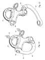
Figure 1 est une vue schématique d'un voilier équipé d'un système d'enroulement selon l'invention montrant la voile d'avant du voilier partiellement hisser. -
Figure 2 est une vue en perspective d'un premier élément du système d'enroulement selon l'invention. -
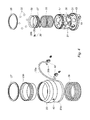
Figure 3 est une vue en coupe d'un deuxième élément du système d'enroulement selon l'invention. -
Figure 4 est une vue éclatée du deuxième élément de lafigure 3 . -
Figure 5 est une vue en perspective d'un troisième élément du système d'enroulement selon l'invention. -
Figures 6 ,8 et10 sont des vues partielle en perspective du système d'enroulement selon l'invention montrant les premier et deuxième éléments dans trois positions différentes de fonctionnement. -
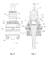
Figures 7 ,9 et11 sont des vues partielle en coupe du système d'enroulement selon l'invention montrant les premier et deuxième éléments respectivement dans les positions de fonctionnement représentées sur lesfigure 6 ,8 et10 . -
Figures 12 sont des vues en perspective d'un mousqueton à ouverture sous charge respectivement en position fermée et en position ouverte.et 13
-
Figure 1 is a schematic view of a sailboat equipped with a winding system according to the invention showing the sail of the sail partially hoisted. -
Figure 2 is a perspective view of a first element of the winding system according to the invention. -
Figure 3 is a sectional view of a second element of the winding system according to the invention. -
Figure 4 is an exploded view of the second element of thefigure 3 . -
Figure 5 is a perspective view of a third element of the winding system according to the invention. -
Figures 6 ,8 and10 are partial perspective views of the winding system according to the invention showing the first and second elements in three different operating positions. -
Figures 7 ,9 and11 are partial sectional views of the winding system according to the invention showing the first and second elements respectively in the operating positions shown in FIGS.figure 6 ,8 and10 . -
Figures 12 and 13 are perspective views of a carabiner with a load opening respectively in the closed position and in the open position.
Comme montré plus particulièrement sur la
Comme montré plus particulièrement sur la
La deuxième portion de fixation 12 comporte une partie filetée 13 agencée pour coopérer avec une partie taraudée 14 ménagée à l'extrémité supérieure de l'étai de soutien 4. La deuxième portion de fixation 12 comporte également une gorge annulaire 15 prolongée en direction de la partie taraudée 14 par une saillie annulaire 16.The
Le deuxième élément 5 comporte un manchon tubulaire 17 délimitant un conduit de passage 18 destiné au passage de l'étai de soutien 4, comme cela est montré notamment sur la
Le deuxième élément 5 comporte en outre deux oeillets de montage 19 solidaires de l'une des extrémités du manchon tubulaire 17 et destinés au montage du coin supérieur de la voile d'avant 6.The
Le manchon tubulaire 17 comporte plusieurs alésages 21 ménagés radialement à travers la paroi du manchon tubulaire 17. Chaque alésage 21 forme un logement pour une bille de verrouillage 22. Chaque bille 22 est déplaçable radialement entre une position de verrouillage (montrée sur la
Le deuxième élément 5 comporte de plus une bague externe 23 montée coulissante autour du manchon tubulaire 17 selon l'axe du manchon tubulaire 17 entre une première position dans laquelle la bague externe 23 sollicite chaque bille 22 vers sa position de verrouillage, et une deuxième position dans laquelle la bague externe 23 autorise un déplacement de chaque bille 22 vers sa position de déverrouillage.The
La bague externe 23 comporte une première portion 24 présentant un premier diamètre intérieur et une deuxième portion 25 présentant un deuxième diamètre intérieur supérieur au premier diamètre. La première portion 24 est agencée pour coopérer avec les billes 22 et immobiliser ces dernières dans leur position de verrouillage lorsque la bague externe 23 est dans sa première position, tandis que la deuxième portion 25 est agencée pour autoriser un déplacement des billes 22 vers leur position de déverrouillage lorsque la bague externe 23 est dans sa deuxième position.The
La bague externe 23 comporte en outre une rampe inclinée 26 ménagée sur la surface intérieure de la bague externe 23 et entre les première et deuxième portions 24, 25. La rampe inclinée 26 est agencée pour solliciter les billes 22 vers leur position de verrouillage lors du déplacement de la bague externe 23 vers sa première position.The
Selon le mode de réalisation de l'invention représenté aux figures, la bague externe 23 comporte un corps 23a réalisé en matière synthétique, et un insert métallique 23b immobilisé par rapport au corps 23a à l'aide d'une part d'un anneau de retenue 27 monté sur le corps 23a et une surface de butée 28 ménagée sur le corps 23a. Selon ce mode de réalisation, les première et deuxième portions 24, 25 et la rampe inclinée 26 sont formées par l'insert métallique 23b.According to the embodiment of the invention shown in the figures, the
Le deuxième élément 5 comporte en outre un ressort de rappel 29 agencé pour solliciter la bague externe 23 vers sa première position. Le ressort de rappel 29 comporte une première extrémité prenant appui contre un retour périphérique externe 31 s'étendant radialement à partir de la surface extérieure du manchon tubulaire 17, et une deuxième extrémité prenant appui contre la bague externe 23.The
Le deuxième élément 5 comporte également une bague interne 32 montée coulissante dans le manchon tubulaire 17 selon l'axe de ce dernier entre une première position dans laquelle la bague interne 32 sollicite chaque bille 22 vers sa position de déverrouillage, et une deuxième position dans laquelle la bague interne 32 autorise un déplacement de chaque bille 22 vers sa position de verrouillage.The
Le deuxième élément 5 comporte un ressort de rappel 33 agencé pour solliciter la bague interne 32 vers sa première position. Le ressort de rappel 33 comporte une première extrémité prenant appui contre un retour périphérique interne 34 s'étendant radialement à partir de la surface intérieure du manchon tubulaire 17, et une deuxième extrémité prenant appui contre la bague interne 17.The
La saillie annulaire 16 du premier élément 2 est agencée pour coopérer avec la bague interne 32 et déplacer cette dernière vers sa deuxième position lorsque le conduit de passage 18 du deuxième élément 5 accueille le premier élément 2.The
Il doit être noté que les billes 22 sont agencées d'une part pour immobiliser la bague externe 23 dans sa deuxième position lorsque la bague interne 32 est dans sa première position, et d'autre part pour libérer la bague externe 23 lorsque la bague interne 32 est déplacée vers sa deuxième position.It should be noted that the
Le deuxième élément 5 comporte des premiers moyens de butée agencés pour limiter la course de déplacement de la bague externe 23 vers sa première position, et des deuxièmes moyens de butée agencés pour limiter la course de déplacement de la bague interne 32 vers sa première position. Les premiers moyens de butée comportent un anneau de retenue 35 monté sur la surface extérieure du manchon tubulaire 17 et agencé pour coopérer avec l'anneau de retenue 27 monté sur le corps 23a de la bague externe 23. Les deuxièmes moyens de butée comportent deux organes de butée 36 comportant chacun une portion de montage 36a insérée dans un orifice 37 ménagé dans la bague interne 32, et une portion de butée 36b faisant saillie à l'extérieur de la bague interne 32 et s'étendant à travers une ouverture 38 ménagée dans le manchon tubulaire 17. La portion de butée 36b de chaque organe de butée 36 est agencée pour coopérer avec la paroi délimitant l'ouverture 38 correspondante lorsque la bague interne 32 est dans sa première position.The
Le deuxième élément 5 comporte enfin une anse de montage 39 montée sur la bague externe 23 et sur laquelle est destinée à être montée une drisse 46 du voilier afin d'assurer un déplacement du deuxième élément 5 le long de l'étai de soutien 4. L'anse de montage 39 comporte une portion centrale 39a et deux portions d'extrémité 39b insérée chacune dans un orifice 40 ménagé la bague externe 23. Chaque orifice 40 débouche dans une gorge annulaire 41 ménagée dans la surface intérieure de la bague externe 23. Le deuxième élément 5 comprend deux organes de retenue 42 logés dans la gorge annulaire 41. Chaque organe de retenue 42 est agencé pour retenir une portion d'extrémité 39b de l'anse de montage 39.The
Le système d'enroulement comporte un témoin de verrouillage 43, avantageusement de couleur vive, prévu pour signaler un état de verrouillage ou de déverrouillage du deuxième élément 5 sur le premier élément 2. Le témoin de verrouillage 43 est disposé sur la surface extérieure du retour périphérique externe 31. La bague externe 23 est agencée pour recouvrir le témoin de verrouillage 43 lorsqu'elle est dans sa deuxième position, et rendre visible le témoin de verrouillage lorsqu'elle est dans sa première position.The winding system comprises a locking
Le système d'enroulement comporte un organe de traction 44, tel qu'un cordage, câble ou similaire, fixé sur l'anse de montage 39 et agencé pour déplacer la bague externe 23 vers sa deuxième position lorsqu'une traction est exercée sur l'organe de traction. L'organe de traction 44 permet ainsi de commander à distance le déplacement des billes de verrouillage 22 vers leur position de déverrouillage. L'organe de traction 44 est avantageusement destiné à être disposé à l'intérieur du fourreau de la voile d'avant 6.The winding system comprises a
Comme montré sur la
Le fonctionnement du système d'enroulement va maintenant être décrit ci-après en supposant qu'initialement la bague interne 32 est dans sa première position, la bague externe 32 dans sa deuxième position, les billes 22 sont dans leur position de déverrouillage, et les premier et deuxième éléments 2, 5 sont déverrouillés. Dans cette situation initiale, l'état du système d'enroulement est celui illustré par les
Lorsqu'un utilisateur souhaite verrouiller le deuxième élément 5 sur le premier élément 2, il déplace le deuxième élément 5 en direction du premier élément 2 de telle sorte que le premier élément pénètre à l'intérieur du manchon tubulaire 17 du deuxième élément. Au cours de cette pénétration du premier élément 2 dans le deuxième élément 5, la saillie annulaire 16 vient en contact contre la bague interne 32, comme cela est représenté sur la
Un tel déplacement des billes 22 vers la gorge annulaire 15 provoque une libération de la bague externe 23 qui est alors sollicitée vers sa première position par le ressort de rappel 29.Such a displacement of the
Lorsque la bague externe 23 vient en butée contre l'anneau de retenue 35, la première portion 24 de la bague externe 23 coopère avec les billes et immobilise ces dernières dans leur position de verrouillage, comme cela est montré sur la
Lorsqu'un utilisateur souhaite déverrouiller le deuxième élément 5, il exerce une traction sur l'organe de traction 44 de manière à déplacer la bague externe 23 vers sa deuxième position. Les billes 22 se retrouvent alors en regard de la deuxième portion 25 de la bague externe 23 et sont donc libres de se déplacer vers leur position de déverrouillage. Les billes 22 sont alors repoussées radialement vers leur position de déverrouillage par le premier élément 2 et immobilisent la bague externe 23 dans sa deuxième position. Il en résulte un déverrouillage du deuxième élément 5 et la possibilité de retirer le premier élément 2 du conduit de passage 18.When a user wishes to unlock the
Le procédé d'hissage de la voile d'avant 6 à l'aide du système d'enroulement selon l'invention sera décrit plus en détail ci-dessous.The method of hoisting the
Un tel procédé comprend les étapes suivantes consistant à :
- fixer la première portion de
fixation 11 dupremier élément 2 en partie supérieure du mât 3, - fixer la deuxième portion de
fixation 12 dupremier élément 2 sur l'extrémité supérieure de l'étai de soutien 4, - insérer l'étai de soutien 4 dans le conduit de passage 18 du deuxième élément 5,
- fixer la première portion de
fixation 8a du troisième élément 8 sur lepont 9 du voilier, - fixer l'extrémité inférieure de l'étai de soutien 4 sur la deuxième portion de
fixation 8b du troisième élément 8, - fixer le coin supérieur de la voile d'avant 6 sur le deuxième élément 5 à l'aide des oeillets 19,
- introduire l'étai de soutien 5 dans le fourreau de la voile d'avant 6,
- monter un mousqueton à ouverture sous charge 45 (voir les
figures 12 et 13 ) sur la drisse 46 du voilier, le mousqueton à ouverture souscharge 45 comprenantun oeillet 47 pour le montage d'une extrémité la drisse 46, uneportion formant crochet 48 mobile entre une position d'accrochage et une position de libération, et des moyens de blocage 49 mobiles entre une position de blocage de laportion formant crochet 47 en position de d'accrochage et une position de libération de la portion formant crochet, - connecter le mousqueton à ouverture sous
charge 45 à l'anse demontage 39 du deuxième élément 5, - relier un cordage ou similaire 51 aux moyens de blocage 49 du mousqueton 45 de telle sorte qu'une traction sur le cordage 51 provoque un déplacement des moyens de blocage vers leur position de libération,
- exercer une traction sur la drisse 46 de manière à déplacer le deuxième élément 5 le long de l'étai de soutien 4 en direction de du
premier élément 2, et ce jusqu'au verrouillage du deuxième élément 5 sur lepremier élément 2 et la visualisation du témoin de verrouillage 43, - exercer une traction sur le cordage 51 relié aux moyens de blocage 49 du mousqueton 45 de manière à déplacer ces derniers vers leur position de libération afin de libérer l'anse de
montage 39 et d'autoriser toute autre utilisation de la drisse 46 pendant que la voile d'avant 6 est hissée, - amarrer l'extrémité inférieure de l'organe de
traction 44 sur la deuxième portion defixation 8b du troisième élément 8, et ce sans exercer de traction sur l'organe detraction 44, et - tendre le guindant de la voile d'avant sur la deuxième portion de
fixation 8b du troisième élément 8.
- fix the first fixing
portion 11 of thefirst element 2 in the upper part of themast 3, - fasten the
second fastening portion 12 of thefirst element 2 to the upper end of thesupport strut 4, - insert the
support stay 4 in the passage duct 18 of thesecond element 5, - fix the
first fastening portion 8a of thethird element 8 on thedeck 9 of the sailboat, - fasten the lower end of the
support stay 4 to thesecond attachment portion 8b of thethird element 8, - attaching the upper corner of the
front sail 6 to thesecond element 5 by means of theeyelets 19, - insert the
support stay 5 into the sheath of thefront sail 6, - mount a carabiner with an opening under load 45 (see
Figures 12 and 13 ) on thehalyard 46 of the sailboat, the carabiner withload opening 45 comprising aneyelet 47 for mounting one end of thehalyard 46, ahook portion 48 movable between a hooking position and a release position, and locking means 49 movable between a locking position of thehook portion 47 in the latching position and a release position of the hook portion, - connect the load-opening
carabiner 45 to the mountinghandle 39 of thesecond element 5, - connecting a rope or the like 51 to the locking means 49 of the
carabiner 45 so that traction on the rope 51 causes the blocking means to move towards their release position, - pulling on the
halyard 46 so as to move thesecond element 5 along thesupport strut 4 in the direction of thefirst element 2, and until thesecond element 5 is locked on thefirst element 2 and thevisualization lock indicator 43, - pulling on the rope 51 connected to the locking means 49 of the
carabiner 45 so as to move the latter to their release position in order to release the mountinghandle 39 and to authorize any other use of thehalyard 46 while thefront sail 6 is hoisted, - mooring the lower end of the
traction member 44 on thesecond fastening portion 8b of thethird element 8, without exerting traction on thetraction member 44, and - tension the luff of the forward sail on the
second fastening portion 8b of thethird element 8.
Le procédé d'affalage de la voile d'avant 6 à l'aide du système d'enroulement selon l'invention comprend une étape consistant à exercer une traction sur l'organe de traction 44 de manière à déplacer la bague externe 23 vers sa deuxième position et provoquer un déplacement des billes 22 vers leur position de déverrouillage. Il en résulte une chute par gravité du deuxième élément 5 et de la voile d'avant 6 le long de l'étai de soutien. La chute de la voile d'avant 6 est freiné par glissement du fourreau de celle-ci le long de l'étai de soutien 4.The method of slackening the
Le procédé d'affalage comprend en outre les étapes consistant à ouvrir le fourreau de la voile d'avant 6 de manière à déconnecter cette dernière de l'étai de soutien 4, et à déconnecter le coin supérieur de la voile d'avant 6 du deuxième élément 5.The luffing method further comprises the steps of opening the sheath of the
Comme il va de soi, l'invention ne se limite pas à la seule forme d'exécution de ce système d'enroulement, décrite ci-dessus à titre d'exemple, elle en embrasse au contraire toutes les variantes de réalisation.As goes without saying, the invention is not limited to the sole embodiment of this winding system, described above as an example, it encompasses all the variants.
Claims (14)
Applications Claiming Priority (1)
| Application Number | Priority Date | Filing Date | Title |
|---|---|---|---|
| FR1158852A FR2980765B1 (en) | 2011-09-30 | 2011-09-30 | SYSTEM FOR WINDING A FORWARD SAIL AROUND A SUPPORT STATUS OF A MATT OF A SAILBOAT |
Publications (1)
| Publication Number | Publication Date |
|---|---|
| EP2574541A1 true EP2574541A1 (en) | 2013-04-03 |
Family
ID=46832306
Family Applications (1)
| Application Number | Title | Priority Date | Filing Date |
|---|---|---|---|
| EP12185156A Withdrawn EP2574541A1 (en) | 2011-09-30 | 2012-09-20 | Furling system of a front sail around a stay of a sailboat |
Country Status (2)
| Country | Link |
|---|---|
| EP (1) | EP2574541A1 (en) |
| FR (1) | FR2980765B1 (en) |
Cited By (3)
| Publication number | Priority date | Publication date | Assignee | Title |
|---|---|---|---|---|
| ITBO20130543A1 (en) * | 2013-10-02 | 2015-04-03 | Gianni Dini | WINDING DEVICE FOR SAILS |
| EP3099568A4 (en) * | 2014-01-28 | 2017-11-01 | Harken, Incorporated | Top down furling system |
| FR3088302A1 (en) * | 2018-11-09 | 2020-05-15 | Fabrication D'accastillage Normand | REMOVABLE HOOKING SYSTEM FOR A SAIL ON A VESSEL AREA FOR SAILING |
Citations (3)
| Publication number | Priority date | Publication date | Assignee | Title |
|---|---|---|---|---|
| US3851610A (en) * | 1973-10-10 | 1974-12-03 | Safe Flight Instrument | Device for selectively preventing rotation of the upper end of a reefed sail and particularly a head sail such as a jib |
| EP0541430A1 (en) * | 1991-11-07 | 1993-05-12 | Proengin S.A. | Jib sail roller-furling system with a swivel joint, lockable to the stay |
| EP2133261A1 (en) * | 2008-06-12 | 2009-12-16 | LUIZY, Olivier, Jean-Marie | Device for winding and stretching a front sail roped or with free hoist for a sail boat |
-
2011
- 2011-09-30 FR FR1158852A patent/FR2980765B1/en active Active
-
2012
- 2012-09-20 EP EP12185156A patent/EP2574541A1/en not_active Withdrawn
Patent Citations (3)
| Publication number | Priority date | Publication date | Assignee | Title |
|---|---|---|---|---|
| US3851610A (en) * | 1973-10-10 | 1974-12-03 | Safe Flight Instrument | Device for selectively preventing rotation of the upper end of a reefed sail and particularly a head sail such as a jib |
| EP0541430A1 (en) * | 1991-11-07 | 1993-05-12 | Proengin S.A. | Jib sail roller-furling system with a swivel joint, lockable to the stay |
| EP2133261A1 (en) * | 2008-06-12 | 2009-12-16 | LUIZY, Olivier, Jean-Marie | Device for winding and stretching a front sail roped or with free hoist for a sail boat |
Cited By (4)
| Publication number | Priority date | Publication date | Assignee | Title |
|---|---|---|---|---|
| ITBO20130543A1 (en) * | 2013-10-02 | 2015-04-03 | Gianni Dini | WINDING DEVICE FOR SAILS |
| EP2857306A1 (en) * | 2013-10-02 | 2015-04-08 | Gianni Dini | Winding device for sails |
| EP3099568A4 (en) * | 2014-01-28 | 2017-11-01 | Harken, Incorporated | Top down furling system |
| FR3088302A1 (en) * | 2018-11-09 | 2020-05-15 | Fabrication D'accastillage Normand | REMOVABLE HOOKING SYSTEM FOR A SAIL ON A VESSEL AREA FOR SAILING |
Also Published As
| Publication number | Publication date |
|---|---|
| FR2980765B1 (en) | 2013-10-04 |
| FR2980765A1 (en) | 2013-04-05 |
Similar Documents
| Publication | Publication Date | Title |
|---|---|---|
| EP2407413B1 (en) | Pulley with unlockable blocker | |
| EP0008560B1 (en) | System for reefing and furling stay sails | |
| EP2574541A1 (en) | Furling system of a front sail around a stay of a sailboat | |
| CA2160260A1 (en) | Fast remote-controlled connecting and disconnecting device | |
| EP1183180B1 (en) | Hooking device for a sail | |
| EP3924070B1 (en) | Connector, releasable dummy fork provided with such a connector and operating method | |
| EP0141766B1 (en) | Safety device for hooking the head of a sail to the mast-head | |
| EP0541430B1 (en) | Jib sail roller-furling system with a swivel joint, lockable to the stay | |
| EP2133261B1 (en) | Device for winding and stretching a front sail roped or with free hoist for a sail boat | |
| EP1765666A1 (en) | Device for stowing away and stretching a front sail of a sailboat | |
| WO2008074930A1 (en) | Device for connecting/disconnecting two members by a relative axial displacement of said members | |
| FR2504084A1 (en) | BOME OF FOC BALLOON OR "SPINNAKER" | |
| WO2014041308A1 (en) | Safety line | |
| EP0310529A1 (en) | Automatic fastening device for a sail at the top of a mast of a boat | |
| WO2006051207A1 (en) | Device for guiding the bolt rope of a sail | |
| EP3272638B1 (en) | Command and control device for sail boat sail or kite wing | |
| FR2698067A1 (en) | Advanced system for winding and remote maneuvering of a spinnaker. | |
| FR3088302A1 (en) | REMOVABLE HOOKING SYSTEM FOR A SAIL ON A VESSEL AREA FOR SAILING | |
| FR2601727A1 (en) | UNBLOCKING MECHANISM HAVING RESISTANCE BY INERTIA, IN PARTICULAR FOR SHIP ROPE | |
| FR2604142A1 (en) | Connecting link between the chain and the cable of a combination anchoring line | |
| FR3033781A1 (en) | ROPE LOCKING AND SELF-TAILING DEVICE ON WINCH FOR SAILBOAT | |
| FR2978118A1 (en) | SAILING ROLLER. | |
| FR3105333A1 (en) | Transmission device, sail winding assembly comprising such a transmission device, and corresponding sailboat | |
| FR2724373A1 (en) | Boat sail halyard tensioner for e.g. sail boards | |
| FR3039504A1 (en) | DEVICE FOR TAKING RIS ON A BOAT SAIL ATTACHED TO A BOME |
Legal Events
| Date | Code | Title | Description |
|---|---|---|---|
| PUAI | Public reference made under article 153(3) epc to a published international application that has entered the european phase |
Free format text: ORIGINAL CODE: 0009012 |
|
| AK | Designated contracting states |
Kind code of ref document: A1 Designated state(s): AL AT BE BG CH CY CZ DE DK EE ES FI FR GB GR HR HU IE IS IT LI LT LU LV MC MK MT NL NO PL PT RO RS SE SI SK SM TR |
|
| AX | Request for extension of the european patent |
Extension state: BA ME |
|
| 17P | Request for examination filed |
Effective date: 20130709 |
|
| RBV | Designated contracting states (corrected) |
Designated state(s): AL AT BE BG CH CY CZ DE DK EE ES FI FR GB GR HR HU IE IS IT LI LT LU LV MC MK MT NL NO PL PT RO RS SE SI SK SM TR |
|
| GRAP | Despatch of communication of intention to grant a patent |
Free format text: ORIGINAL CODE: EPIDOSNIGR1 |
|
| RIC1 | Information provided on ipc code assigned before grant |
Ipc: B63H 9/10 20060101AFI20131021BHEP |
|
| INTG | Intention to grant announced |
Effective date: 20131126 |
|
| RIN1 | Information on inventor provided before grant (corrected) |
Inventor name: LEFLOT, CLEMENT Inventor name: JOSSE, CARL |
|
| STAA | Information on the status of an ep patent application or granted ep patent |
Free format text: STATUS: THE APPLICATION IS DEEMED TO BE WITHDRAWN |
|
| 18D | Application deemed to be withdrawn |
Effective date: 20140408 |