EP2574524A2 - Servolenksystem - Google Patents
Servolenksystem Download PDFInfo
- Publication number
- EP2574524A2 EP2574524A2 EP12185360A EP12185360A EP2574524A2 EP 2574524 A2 EP2574524 A2 EP 2574524A2 EP 12185360 A EP12185360 A EP 12185360A EP 12185360 A EP12185360 A EP 12185360A EP 2574524 A2 EP2574524 A2 EP 2574524A2
- Authority
- EP
- European Patent Office
- Prior art keywords
- rotation speed
- threshold
- electric motor
- power
- equal
- Prior art date
- Legal status (The legal status is an assumption and is not a legal conclusion. Google has not performed a legal analysis and makes no representation as to the accuracy of the status listed.)
- Withdrawn
Links
Images
Classifications
-
- B—PERFORMING OPERATIONS; TRANSPORTING
- B62—LAND VEHICLES FOR TRAVELLING OTHERWISE THAN ON RAILS
- B62D—MOTOR VEHICLES; TRAILERS
- B62D5/00—Power-assisted or power-driven steering
- B62D5/06—Power-assisted or power-driven steering fluid, i.e. using a pressurised fluid for most or all the force required for steering a vehicle
- B62D5/065—Power-assisted or power-driven steering fluid, i.e. using a pressurised fluid for most or all the force required for steering a vehicle characterised by specially adapted means for varying pressurised fluid supply based on need, e.g. on-demand, variable assist
Definitions
- the invention relates to a power steering system that generates steering assist force with the use of a hydraulic pump driven by an electric motor.
- a conventional power steering system that assists an operation of a steering member such as a steering wheel, by supplying hydraulic fluid from a hydraulic pump to a power cylinder coupled to a steering mechanism such as a rack-and-pinion mechanism.
- an electric motor formed of, for example, a three-phase brushless motor may be used as a driving source for the hydraulic pump.
- driving electric power that is supplied to the electric motor is controlled such that the electric motor is rotated at a target rotation speed that corresponds to a steering speed of the steering wheel.
- JP 06-206572 A describes a power steering system that determines that a steering operation is not immediately performed and an electric motor is stopped, when a vehicle speed is zero, a steering angular velocity is zero, and a turn signal switch is off.
- the electric motor is stopped. That is, even when steering assist force is required, the electric motor may be stopped.
- the invention provides a power steering system that makes it possible to achieve power saving and to avoid a situation where an electric motor is stopped or the rotation speed of the electric motor is controlled to a low speed when steering assist force is required.
- a power-saving process for stopping an electric motor or controlling a rotation speed of the electric motor to a rotation speed that is lower than a rotation speed in normal mode is executed.
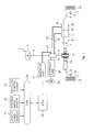
- FIG. 1 is a schematic view that shows the schematic configuration of a power steering system according to an embodiment of the invention.
- the power steering system 1 is provided in association with a steering mechanism 2 of a vehicle, and is used to apply steering assist force to the steering mechanism 2.
- the steering mechanism 2 includes a steering wheel 3, a steering shaft 4, a pinion shaft 5, and a rack shaft 7.
- the steering wheel 3 serves as a steering member that is operated by a driver to steer the vehicle.
- the steering shaft 4 is coupled to the steering wheel 3.
- the pinion shaft 5 is coupled to the distal end portion of the steering shaft 4 via a hydraulic control valve 14, and has a pinion gear 6.
- the rack shaft 7 has a rack gear portion 7a that is in mesh with the pinion gear 6, and serves as a steered shaft that extends in the lateral direction of the vehicle.
- Tie rods 8 are coupled to respective ends of the rack shaft 7.
- the tie rods 8 are coupled to respective knuckle arms 11 that respectively support right and left steered wheels 10, 9.
- Each knuckle arm 11 is provided so as to be pivotable about a kingpin 12.
- the hydraulic control valve 14 is a rotary valve, and is formed of a sleeve valve element (not shown) connected to the steering shaft 4, a shaft valve element (not shown) connected to the pinion shaft 5, and a torsion bar (not shown) that couples these valve elements to each other.
- the torsion bar is twisted in response to the direction and magnitude of steering torque that is applied to the steering wheel 3, and the opening degree of the hydraulic control valve 14 is changed in accordance with the direction and magnitude of torsion of the torsion bar.
- the hydraulic control valve 14 is connected to a power cylinder 15 that applies steering assist force to the steering mechanism 2.
- the power cylinder 15 includes a piston 16 fixed to the rack shaft 7 and a pair of cylinder chambers 17, 18 separated by the piston 16.
- the cylinder chambers 17, 18 are connected to the hydraulic control valve 14 via oil passages 19, 20, respectively.
- the hydraulic control valve 14 is provided on an oil circulating passage 23 that passes through a reservoir tank 21 and a hydraulic pump 22 that generates steering assist force.
- the hydraulic pump 22 is formed of, for example, a gear pump, and is driven by an electric motor 24.
- the hydraulic pump 22 draws the hydraulic fluid stored in the reservoir tank 21 and supplies the hydraulic fluid to the hydraulic control valve 14.
- the excess hydraulic fluid is returned from the hydraulic control valve 14 to the reservoir tank 21 via the oil circulating passage 23.
- the electric motor 24 is rotated in one direction to drive the hydraulic pump 22.
- the output shaft of the electric motor 24 is coupled to the input shaft of the hydraulic pump 22.
- the input shaft of the hydraulic pump 22 rotates.
- the hydraulic pump 22 is driven.
- the hydraulic fluid is supplied to one of the cylinder chambers 17, 18 of the power cylinder 15 via a corresponding one of the oil passages 19, 20, and the hydraulic fluid in the other one of the cylinder chambers is returned to the reservoir tank 21.
- the electric motor 24 is formed of a three-phase brushless motor, and is controlled by an electronic control unit (ECU) 30.
- An in-vehicle LAN (control area network (CAN)) 26 is formed in the vehicle.
- the above-described ECU 30 is connected to the in-vehicle LAN 26.
- a vehicle speed sensor 71, a steering angle sensor 72, a rotation position sensor 73 and other sensors are connected to the in-vehicle LAN 26.
- the vehicle speed sensor 71 is used to detect a speed Vs of the vehicle.
- the steering angle sensor 72 is used to detect a steering angle ⁇ h of the steering wheel 3 that is operated by the driver.
- the rotation position sensor 73 is used to detect a rotation position of a rotor of the electric motor 24.
- the ECU 30 executes drive control over the electric motor 24 on the basis of, for example, the detected signal from the vehicle speed sensor 71, the steering angle sensor 72 and the rotation position sensor 73 such that appropriate steering assist force is applied to the steering mechanism 2.
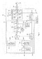
- FIG. 2 is a block diagram that shows the electrical configuration of the ECU 30.
- the ECU 30 includes a microcomputer 31, a driving circuit (inverter circuit) 32, a shunt resistor 33 and a current detecting unit 34.
- the driving circuit 32 is controlled by the microcomputer 31 and supplies electric power to the electric motor 24.
- the current detecting unit 34 is used to detect a motor current (consumption current) that flows through the motor 24.
- the driving circuit 32 is a three-phase bridge inverter circuit.
- a series circuit formed of a pair of field effect transistors (FETs) 41UH, 41UL, which correspond to the U-phase of the electric motor 24, a series circuit formed of a pair of FETs 41 VH, 41 VL, which correspond to the V-phase of the electric motor 24 and a series circuit formed of a pair of FETs 41WH, 41WL, which correspond to the W-phase of the electric motor 24, are connected in parallel with each other between a direct-current power supply 42 and a ground 43.
- FETs field effect transistors
- a U-phase field coil (not shown) of the electric motor 24 is connected to a connection point between the FETs 41UH, 41UL which correspond to the U-phase.
- a V-phase field coil (not shown) of the electric motor 24 is connected to a connection point between the FETs 41 VH, 41 VL which correspond to the V-phase.
- a W-phase field coil (not shown) of the electric motor 24 is connected to a connection point between the FETs 41 WH, 41 WL which correspond to the W-phase.
- the shunt resistor 33 is connected to a line, at a position between the ground side of the driving circuit 32 and the ground 43.
- the current detecting unit 34 is used to detect a motor current (consumption current) Im on the basis of an inter-terminal voltage of the shunt resistor 33.
- the microcomputer 31 includes a CPU and memories (e.g. a ROM, a RAM, a nonvolatile memory), and is configured to function as a plurality of functional processing units by executing predetermined programs.
- the functional processing units include a steering angular velocity computing unit 51, a first target rotation speed setting unit 52, a second target rotation speed setting unit 53, a target rotation speed changing unit 54, a rotation position computing unit 55, a rotation speed computing unit 56, a speed deviation computing unit 57, a PI control unit 58, a PWM control unit 59, and a change control unit 60.
- control modes of the electric motor 24 include a normal mode and a power-saving mode.
- the microcomputer 31 executes a power-saving process for stopping the electric motor 24 or controlling the rotation speed of the electric motor 24 to a speed lower than a rotation speed in the normal mode.
- description will be made on a case where, in the power-saving mode, the rotation speed of the electric motor 24 is controlled to a speed lower than the rotation speed in the normal mode.
- the steering angular velocity computing unit 51 computes a steering angular velocity Vh by subjecting a value output from the steering angle sensor 72 to temporal differentiation.
- the first target rotation speed setting unit 52 is used to set a target rotation speed of the electric motor 24 in the normal mode.
- the first target rotation speed setting unit 52 sets a target rotation speed (hereinafter, referred to as "first target rotation speed Vp1*") of the electric motor 24 on the basis of the steering angular velocity Vh computed by the steering angular velocity computing unit 51.
- the first target rotation speed setting unit 52 sets the first target rotation speed Vp1* on the basis of, for example, a map that stores the correlation between the steering angular velocity and the first target rotation speed Vp1*.
- the first target rotation speed Vp1* takes a lower limit value (for example, 2500 rpm) when the steering angular velocity falls within a relatively low first range.
- the first target rotation speed Vp1* takes an upper limit value (for example, 3500 rpm) when the steering angular velocity falls within a relatively high second range.
- the first target rotation speed Vp1* is set to increase as the steering angular velocity increases within a range between the lower limit value and the upper limit value, when the steering angular velocity falls within a range between the first range and the second range.
- the second target rotation speed setting unit 53 is used to set a target rotation speed (hereinafter, referred to as "second target rotation speed Vp2*") of the electric motor 24 in the power-saving mode.
- the second target rotation speed Vp2* is set to a value lower than the target rotation speed in the normal mode, that is, for example, 1000 rpm.
- the second target rotation speed Vp2* is preferably set higher than or equal to 1000 rpm. This is because, if the target rotation speed of the electric motor 24 (hydraulic pump 22) is set lower than 1000 rpm, formation of an oil film may be insufficient, which may cause a failure in the hydraulic pump 22.
- the target rotation speed changing unit 54 selects one of the first target rotation speed Vp1* set by the first target rotation speed setting unit 52 and the second target rotation speed Vp2* set by the second target rotation speed setting unit 53, and provides the selected target rotation speed to the speed deviation computing unit 57.
- the change control unit 60 generates a mode change command for changing the control mode between the normal mode and the power-saving mode on the basis of the vehicle speed Vs detected by the vehicle speed sensor 71, the steering angular velocity Vh computed by the steering angular velocity computing unit 51, and the motor current Im detected by the current detecting unit 34.
- the control mode is changed in the target rotation speed changing unit 54.
- the target rotation speed changing unit 54 selects and outputs the first target rotation speed Vp1* set by the first target rotation speed setting unit 52.
- the target rotation speed changing unit 54 selects and outputs the second target rotation speed Vp2* set by the second target rotation speed setting unit 53.
- the rotation position computing unit 55 computes a rotor rotation position of the electric motor 24 on the basis of a detected signal from the rotation position sensor 73.
- the rotation speed computing unit 56 computes a rotation speed (actual rotation speed) Vp of the electric motor 24 on the basis of the rotor rotation position computed by the rotation position computing unit 55.
- the PI control unit 58 executes PI computation on the speed deviation ⁇ Vp computed by the speed deviation computing unit 57. That is, the speed deviation computing unit 57 and the PI control unit 58 constitute speed feedback control means for bringing the rotation speed Vp of the electric motor 24 to the target rotation speed Vp*.
- the PI control unit 58 executes PI computation on the speed deviation ⁇ Vp to compute a control voltage value that is a value of voltage that should be applied to the electric motor 24.
- the PWM control unit 59 generates a driving signal on the basis of the control voltage value computed by the PI control unit 58 and the rotor rotation position computed by the rotation position computing unit 55, and provides the driving signal to the driving circuit 32.
- a voltage based on the control voltage value computed by the PI control unit 58 is applied from the driving circuit 32 to the electric motor 24. That is, when the control mode is the normal mode, drive control of the electric motor 24 is executed such that the rotation speed Vp computed by the rotation speed computing unit 56 becomes equal to the first target rotation speed Vp1* set by the first target rotation speed setting unit 52.
- control mode is the power-saving mode
- drive control of the electric motor 24 is executed such that the rotation speed Vp computed by the rotation speed computing unit 56 becomes equal to the second target rotation speed Vp2* set by the second target rotation speed setting unit 53.
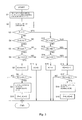
- FIG. 3 is a flowchart that shows operations of the change control unit 60.
- the process of FIG. 3 is repeatedly executed at predetermined computation cycles.
- the change control unit 60 first receives the vehicle speed V, which is detected by the vehicle speed sensor 71, via the in-vehicle LAN 26, and acquires the steering angular velocity Vh from the steering angular velocity computing unit 51 (step S1). Then, the change control unit 60 acquires the motor current Im from the current detecting unit 34 (step S2).
- the change control unit 60 determines whether a mode flag F is set (step S3).
- the mode flag F is reset in an initial state.
- the change control unit 60 determines whether the vehicle speed Vs is lower than or equal to a predetermined threshold A1 (step S4).
- the threshold A1 is set to, for example, a value higher than or equal to 0 km/h and lower than or equal to 5 km/h. In the present embodiment, the threshold A1 is set to 1 km/h.
- the change control unit 60 determines whether the steering angular velocity Vh is lower than or equal to a predetermined threshold B1 (step S5).
- the threshold B1 is set to, for example, a value higher than or equal to 1 degree/sec and lower than or equal to 10 degrees/sec. In the present embodiment, the threshold B1 is set to 10 degrees/sec.
- the change control unit 60 determines whether the motor current Im is smaller than or equal to a predetermined threshold C1 (step S6).
- the threshold C1 is set to, for example, a value larger than or equal to 5 A and lower than or equal to 10A. In the present embodiment, the threshold C1 is set to 5 A.
- step S6 When the motor current Im is smaller than or equal to the threshold C1 (YES in step S6), the change control unit 60 increments a first count value K1 by one (+1) (step S7). An initial value of the first count value K1 is zero. Then, the change control unit 60 determines whether the first count value K1 is larger than or equal to a predetermined threshold D1 (step S8). When the first count value K1 is smaller than the threshold D1 (NO in step S8), the change control unit 60 ends the process in the current computation cycle.
- step S8 it is determined whether the duration of a state where the vehicle speed Vs is lower than or equal to the threshold A1, the steering angular velocity Vh is lower than or equal to the threshold B1 and the motor current Im is smaller than or equal to the threshold C1 is longer than or equal to a first predetermined time defined by the threshold D1.
- the first predetermined time is set to, for example, 5 sec.
- step S8 When it is determined in step S8 that the first count value K1 is larger than or equal to the threshold D1 (YES in step S8), the change control unit 60 changes the control mode to the power-saving mode (step S9). Specifically, the change control unit 60 controls the target rotation speed changing unit 54 such that the target rotation speed changing unit 54 selects and outputs the second target rotation speed Vp2*.
- the change control unit 60 determines whether the vehicle speed Vs is higher than a predetermined threshold A2 (step S12).
- the threshold A2 is set to a value higher than or equal to the threshold A1. In the present embodiment, the threshold A2 is set to 1 km/h.
- the change control unit 60 determines whether the steering angular velocity Vh is higher than a predetermined threshold B2 (step S13).
- the threshold B2 is set to a value higher than or equal to the threshold B1. In the present embodiment, the threshold B2 is set to 10 degrees/sec.
- the change control unit 60 determines whether the motor current Im is larger than a predetermined threshold C2 (step S14).
- the threshold C2 is set to a value larger than or equal to the threshold C1. In the present embodiment, the threshold C2 is set to 5 A.
- step S12 When it is determined in step S12 that the vehicle speed Vs is higher than the threshold A2 (YES in step S12), when it is determined in step S13 that the steering angular velocity Vh is higher than the threshold B2 (YES in step S13) or when it is determined in step S14 that the motor current Im is larger than the threshold C2 (YES in step S14), the change control unit 60 increments the second count value K2 by one (+1) (step S16).
- the change control unit 60 determines whether the second count value K2 is larger than or equal to a predetermined value D2 (step S17). That is, it is determined whether the duration of a state where at least one of a condition that the vehicle speed Vs is higher than the threshold A2, a condition that the steering angular velocity Vh is higher than the threshold B2 and a condition that the motor current Im is larger than the threshold C2 is satisfied is longer than or equal to a second predetermined time defined by the threshold D2.
- the second predetermined time is set to, for example, 0.1 sec.
- the change control unit 60 ends the process in the current computation cycle.
- the change control unit 60 changes the control mode to the normal mode (step S18). Specifically, the change control unit 60 controls the target rotation speed changing unit 54 such that the target rotation speed changing unit 54 selects and outputs the first target rotation speed Vp1*.
- the change control unit 60 while drive control of the electric motor 24 is being executed in the normal mode, when the duration of a state where the vehicle speed Vs is lower than or equal to the threshold A1, the steering angular velocity Vh is lower than or equal to the threshold B1 and the motor current Im is smaller than or equal to the threshold C1 is longer than or equal to the first predetermined time defined by the threshold D1, it is determined that that the possibility that a steering operation is performed is low, and the control mode is changed to the power-saving mode.
- the target rotation speed Vp* of the electric motor 24 is changed from the first target rotation speed Vp1* to the second target rotation speed Vp2*.
- the rotation speed of the electric motor 24 is controlled to be lower than the rotation speed in the normal mode. As a result, power saving is achieved.
- the control mode is not changed to the power-saving mode. Therefore, it is possible to avoid a situation where the control mode is changed to the power-saving mode during warm-up operation. Even after a load on the electric motor 24 decreases through warm-up operation and then the motor current Im becomes lower than or equal to the threshold C1, if the warm-up operation is still continued, the control mode is changed to the power-saving mode.
- the second target rotation speed setting unit 53 sets and outputs the predetermined second target rotation speed Vp2*.
- a target rotation speed that gradually decreases from the target rotation speed Vp* immediately before the mode change to the second target rotation speed Vp2* may be set and output.
- the first target rotation speed setting unit 52 sets and outputs the first target rotation speed Vp1* based on the steering angular velocity.
- a target rotation speed that gradually increases from the target rotation speed Vp* immediately before the mode change to the first target rotation speed Vp1* based on the steering angular velocity may be set and output.
- the control mode may be changed to the normal mode.
- the third predetermined time, the fourth predetermined time and the fifth predetermined time may be equal to, for example, the second predetermined time.
- the rotation speed of the electric motor 24 is controlled be lower than the rotation speed during the normal mode.
- the electric motor 24 may be stopped in the power-saving mode.
- the motor current is detected on the basis of the inter-terminal voltage of the shunt resistor 33.
- the motor current may be detected on the basis of at least one of U-phase current, V-phase current and W-phase current.
- the rotation speed of the electric motor 24 may be regarded as a constant value and the root mean square (rms) of one-phase current may be detected as a consumption current.
Applications Claiming Priority (1)
| Application Number | Priority Date | Filing Date | Title |
|---|---|---|---|
| JP2011211290A JP2013071559A (ja) | 2011-09-27 | 2011-09-27 | パワーステアリング装置 |
Publications (2)
| Publication Number | Publication Date |
|---|---|
| EP2574524A2 true EP2574524A2 (de) | 2013-04-03 |
| EP2574524A3 EP2574524A3 (de) | 2013-11-13 |
Family
ID=46970054
Family Applications (1)
| Application Number | Title | Priority Date | Filing Date |
|---|---|---|---|
| EP12185360.0A Withdrawn EP2574524A3 (de) | 2011-09-27 | 2012-09-21 | Servolenksystem |
Country Status (4)
| Country | Link |
|---|---|
| US (1) | US20130079992A1 (de) |
| EP (1) | EP2574524A3 (de) |
| JP (1) | JP2013071559A (de) |
| CN (1) | CN103010297A (de) |
Cited By (1)
| Publication number | Priority date | Publication date | Assignee | Title |
|---|---|---|---|---|
| US10947982B2 (en) | 2014-02-06 | 2021-03-16 | Hyundai Motor Company | Method of determining circulation state of cooling water |
Families Citing this family (12)
| Publication number | Priority date | Publication date | Assignee | Title |
|---|---|---|---|---|
| CN103253298A (zh) * | 2013-04-16 | 2013-08-21 | 中国电子科技集团公司第三十六研究所 | 电机驱动的液压助力转向泵 |
| JP6365866B2 (ja) * | 2013-11-22 | 2018-08-01 | 株式会社ジェイテクト | パワーステアリング装置 |
| CN103631281B (zh) * | 2013-12-06 | 2016-01-13 | 江苏科技大学 | 一种液压马达角速度伺服系统 |
| JP6372177B2 (ja) * | 2014-06-11 | 2018-08-15 | 株式会社ジェイテクト | 搬送システム |
| DE102014220646A1 (de) * | 2014-10-13 | 2016-04-14 | Bayerische Motoren Werke Aktiengesellschaft | Nutzung einer Bus-Leitung zur Übertragung alternativer Signalcodierungen |
| JP6482437B2 (ja) * | 2015-09-03 | 2019-03-13 | 日立オートモティブシステムズ株式会社 | パワーステアリング装置 |
| KR102376065B1 (ko) * | 2015-10-12 | 2022-03-18 | 현대모비스 주식회사 | 전동식 조향 장치의 제어 방법 |
| CN106741155A (zh) * | 2016-11-24 | 2017-05-31 | 金龙联合汽车工业(苏州)有限公司 | 一种新能源客车电动液压助力转向系统及其控制方法 |
| CN109017980A (zh) * | 2018-07-23 | 2018-12-18 | 金龙联合汽车工业(苏州)有限公司 | 一种客车电动转向泵随速控制方法 |
| CN111216789A (zh) * | 2018-11-27 | 2020-06-02 | 郑州宇通客车股份有限公司 | 一种电动液压助力转向电机转速控制方法及系统、车辆 |
| CN113454908A (zh) * | 2019-02-28 | 2021-09-28 | 三菱电机株式会社 | 马达驱动装置以及空调机 |
| CN114620124B (zh) * | 2022-03-31 | 2023-03-24 | 东风商用车有限公司 | 应急转向泵控制方法、装置、设备及可读存储介质 |
Citations (1)
| Publication number | Priority date | Publication date | Assignee | Title |
|---|---|---|---|---|
| JPH06206572A (ja) | 1993-01-12 | 1994-07-26 | Unisia Jecs Corp | 動力操向装置の操舵力制御装置 |
Family Cites Families (5)
| Publication number | Priority date | Publication date | Assignee | Title |
|---|---|---|---|---|
| US6073721A (en) * | 1998-06-01 | 2000-06-13 | Ford Global Technologies, Inc. | Method for limiting hydraulic assist in a power assist steering system |
| DE10325848A1 (de) * | 2003-06-06 | 2005-01-05 | Trw Fahrwerksysteme Gmbh & Co. Kg | Verfahren zur Steuerung eines elektrischen Pumpenantriebsmotors einer Servolenkvorrichtung |
| KR100969101B1 (ko) * | 2008-05-20 | 2010-07-09 | 현대자동차주식회사 | 모터제어식 유압파워스티어링 시스템의 소비전류 저감 방법 |
| FR2935670B1 (fr) * | 2008-09-11 | 2011-08-05 | Jtekt Hpi | Procede de strategie de reduction de la consommation d'energie d'un vehicule automobile. |
| US8150579B2 (en) * | 2009-03-27 | 2012-04-03 | GM Global Technology Operations LLC | Pump speed command generation algorithm for magnetorheological power steering coupling |
-
2011
- 2011-09-27 JP JP2011211290A patent/JP2013071559A/ja not_active Withdrawn
-
2012
- 2012-09-18 CN CN2012103477530A patent/CN103010297A/zh active Pending
- 2012-09-19 US US13/622,601 patent/US20130079992A1/en not_active Abandoned
- 2012-09-21 EP EP12185360.0A patent/EP2574524A3/de not_active Withdrawn
Patent Citations (1)
| Publication number | Priority date | Publication date | Assignee | Title |
|---|---|---|---|---|
| JPH06206572A (ja) | 1993-01-12 | 1994-07-26 | Unisia Jecs Corp | 動力操向装置の操舵力制御装置 |
Cited By (1)
| Publication number | Priority date | Publication date | Assignee | Title |
|---|---|---|---|---|
| US10947982B2 (en) | 2014-02-06 | 2021-03-16 | Hyundai Motor Company | Method of determining circulation state of cooling water |
Also Published As
| Publication number | Publication date |
|---|---|
| EP2574524A3 (de) | 2013-11-13 |
| CN103010297A (zh) | 2013-04-03 |
| US20130079992A1 (en) | 2013-03-28 |
| JP2013071559A (ja) | 2013-04-22 |
Similar Documents
| Publication | Publication Date | Title |
|---|---|---|
| EP2574524A2 (de) | Servolenksystem | |
| US10494018B2 (en) | Steering device | |
| EP3315383B1 (de) | Lenkvorrichtung | |
| US9415801B2 (en) | Power steering system | |
| EP2323250B1 (de) | Motorsteuereinheit und Fahrzeuglenksystem | |
| US8813902B2 (en) | Hydraulic power steering system | |
| US9079609B2 (en) | Hydraulic power steering system | |
| EP2557019B1 (de) | Hydraulisches Servolenksystem | |
| JP6120074B2 (ja) | 車両用操舵装置 | |
| EP2597015B1 (de) | Hydraulisches Servolenksystem | |
| JP4247668B2 (ja) | パワーステアリング装置 | |
| JP6020881B2 (ja) | 油圧式パワーステアリング装置 | |
| JP2012176741A (ja) | 電動パワーステアリング装置 | |
| JP6922508B2 (ja) | パワーステアリング装置 | |
| JP4178221B2 (ja) | パワーステアリング装置 | |
| JP2005193700A (ja) | パワーステアリング装置 | |
| JP2015098210A (ja) | 油圧パワーステアリング装置の制御装置 | |
| JP2020011585A (ja) | 操舵制御装置 |
Legal Events
| Date | Code | Title | Description |
|---|---|---|---|
| PUAI | Public reference made under article 153(3) epc to a published international application that has entered the european phase |
Free format text: ORIGINAL CODE: 0009012 |
|
| AK | Designated contracting states |
Kind code of ref document: A2 Designated state(s): AL AT BE BG CH CY CZ DE DK EE ES FI FR GB GR HR HU IE IS IT LI LT LU LV MC MK MT NL NO PL PT RO RS SE SI SK SM TR |
|
| AX | Request for extension of the european patent |
Extension state: BA ME |
|
| PUAL | Search report despatched |
Free format text: ORIGINAL CODE: 0009013 |
|
| AK | Designated contracting states |
Kind code of ref document: A3 Designated state(s): AL AT BE BG CH CY CZ DE DK EE ES FI FR GB GR HR HU IE IS IT LI LT LU LV MC MK MT NL NO PL PT RO RS SE SI SK SM TR |
|
| AX | Request for extension of the european patent |
Extension state: BA ME |
|
| RIC1 | Information provided on ipc code assigned before grant |
Ipc: B62D 5/065 20060101AFI20131008BHEP |
|
| STAA | Information on the status of an ep patent application or granted ep patent |
Free format text: STATUS: THE APPLICATION IS DEEMED TO BE WITHDRAWN |
|
| 18D | Application deemed to be withdrawn |
Effective date: 20140514 |