EP2573607A2 - Bildverarbeitungsvorrichtung, Fluoreszenzmikroskopvorrichtung und Bildverarbeitungsprogramm - Google Patents
Bildverarbeitungsvorrichtung, Fluoreszenzmikroskopvorrichtung und Bildverarbeitungsprogramm Download PDFInfo
- Publication number
- EP2573607A2 EP2573607A2 EP12006571A EP12006571A EP2573607A2 EP 2573607 A2 EP2573607 A2 EP 2573607A2 EP 12006571 A EP12006571 A EP 12006571A EP 12006571 A EP12006571 A EP 12006571A EP 2573607 A2 EP2573607 A2 EP 2573607A2
- Authority
- EP
- European Patent Office
- Prior art keywords
- luminance
- fluorescence
- images
- specimen
- image
- Prior art date
- Legal status (The legal status is an assumption and is not a legal conclusion. Google has not performed a legal analysis and makes no representation as to the accuracy of the status listed.)
- Granted
Links
- 238000002073 fluorescence micrograph Methods 0.000 claims abstract description 47
- 238000009499 grossing Methods 0.000 claims abstract description 12
- 230000003287 optical effect Effects 0.000 claims description 44
- 230000005284 excitation Effects 0.000 claims description 9
- 230000035945 sensitivity Effects 0.000 claims description 4
- 238000001917 fluorescence detection Methods 0.000 claims description 2
- 235000019557 luminance Nutrition 0.000 description 109
- 230000004048 modification Effects 0.000 description 11
- 238000012986 modification Methods 0.000 description 11
- 238000001514 detection method Methods 0.000 description 8
- 238000010586 diagram Methods 0.000 description 6
- 238000005286 illumination Methods 0.000 description 4
- 230000002146 bilateral effect Effects 0.000 description 3
- 230000003247 decreasing effect Effects 0.000 description 3
- 238000000034 method Methods 0.000 description 3
- 230000007935 neutral effect Effects 0.000 description 3
- 239000000126 substance Substances 0.000 description 3
- 230000001276 controlling effect Effects 0.000 description 2
- 230000000875 corresponding effect Effects 0.000 description 2
- 238000009826 distribution Methods 0.000 description 2
- 238000005516 engineering process Methods 0.000 description 2
- 238000003384 imaging method Methods 0.000 description 2
- 230000005540 biological transmission Effects 0.000 description 1
- 238000006243 chemical reaction Methods 0.000 description 1
- 230000002596 correlated effect Effects 0.000 description 1
- 230000000694 effects Effects 0.000 description 1
- 238000005259 measurement Methods 0.000 description 1
- QSHDDOUJBYECFT-UHFFFAOYSA-N mercury Chemical compound [Hg] QSHDDOUJBYECFT-UHFFFAOYSA-N 0.000 description 1
- 229910052753 mercury Inorganic materials 0.000 description 1
- 238000003672 processing method Methods 0.000 description 1
- 229920006395 saturated elastomer Polymers 0.000 description 1
Images


Classifications
-
- G—PHYSICS
- G02—OPTICS
- G02B—OPTICAL ELEMENTS, SYSTEMS OR APPARATUS
- G02B21/00—Microscopes
- G02B21/0004—Microscopes specially adapted for specific applications
- G02B21/002—Scanning microscopes
- G02B21/0024—Confocal scanning microscopes (CSOMs) or confocal "macroscopes"; Accessories which are not restricted to use with CSOMs, e.g. sample holders
- G02B21/0052—Optical details of the image generation
- G02B21/0076—Optical details of the image generation arrangements using fluorescence or luminescence
-
- G—PHYSICS
- G02—OPTICS
- G02B—OPTICAL ELEMENTS, SYSTEMS OR APPARATUS
- G02B21/00—Microscopes
- G02B21/0004—Microscopes specially adapted for specific applications
- G02B21/002—Scanning microscopes
- G02B21/0024—Confocal scanning microscopes (CSOMs) or confocal "macroscopes"; Accessories which are not restricted to use with CSOMs, e.g. sample holders
- G02B21/008—Details of detection or image processing, including general computer control
Definitions
- the present invention relates to an image processing apparatus, a fluorescence microscope apparatus, and an image processing program.
- the present invention has been conceived in light of the above-described circumstances, and an object thereof is to provide an image processing apparatus, a fluorescence microscope apparatus, and an image processing program which make it possible to generate a three-dimensional image without luminance irregularity while achieving good contrast.
- a first aspect of the present invention is an image processing apparatus including an image combining portion that generates combined images by combining, for each depth position in a specimen, a plurality of fluorescence images captured with differing exposure levels at each depth position, which are fluorescence images generated by capturing fluorescence coming from the specimen at different depth positions in the specimen; a smoothed-luminance calculating portion that calculates a representative luminance from the individual combined images generated by the image combining portion and that calculates a smoothed luminance for the individual combined images by smoothing the calculated representative luminance in the depth direction; a luminance correcting portion that generates corrected images by correcting the luminance of the individual combined images on the basis of differences between the smoothed luminance and the representative luminance calculated by the smoothed-luminance calculating portion; and a three-dimensional image generating portion that generates a three-dimensional image of the specimen from the plurality of corrected images generated by the luminance correcting portion.
- the image combining portion by combining the plurality of fluorescence images for the same depth positions with the differing exposure levels, the image combining portion generates combined images in which dynamic ranges are expanded with respect to the original fluorescence images. Then, the luminance correcting portion generates the corrected images by correcting the luminance of the combined images, and the three-dimensional image generating portion generates a three-dimensional image of the specimen from the corrected images.
- the individual combined images have different dynamic ranges depending on the fluorescence intensities of the plurality of original fluorescence images.
- the smoothed-luminance calculating portion performs smoothing of the representative luminance in the depth direction of the specimen.
- the luminance correcting portion generates the corrected images in which the luminance smoothly changes in the depth direction of the specimen. By doing so, it is possible to generate a three-dimensional image from the corrected images without stripe-patterned luminance irregularity while achieving good contrast.
- a second aspect of the present invention is a fluorescence microscope apparatus including a light source that radiates excitation light onto a specimen; an objective optical system that collects fluorescence generated at the specimen due to the irradiation with the excitation light; an image capturing portion that captures the fluorescence collected by the objective optical system; a focal-position controller that causes the image capturing portion to capture images of the specimen at a plurality of focal positions by moving the focal position of the objective optical system in the optical axis direction of the objective optical system; an exposure-level controller that causes the image capturing portion to capture the fluorescence multiple times at the individual focal positions with differing exposure levels; an image combining portion that generates combined images by combining the plurality of fluorescence images acquired by the image capturing portion at each focal position in accordance with the control by the focal-position controller and the exposure-level controller; a smoothed-luminance calculating portion that calculates a representative luminance from the individual combined images generated by the image combining portion and that calculates a smoothed luminance for
- the image capturing portion captures the fluorescence generated at the specimen due to irradiation with the excitation light from the light source.
- the image capturing portion acquires the fluorescence images at the plurality of focal positions on the basis of the control by the focal-position controller, and, furthermore, the image capturing portion acquires the plurality of fluorescence images with differing exposure levels at the individual focal positions on the basis of the control by the exposure-level controller.
- the image combining portion By combining the plurality of fluorescence images from the individual focal positions, the image combining portion generates combined images whose dynamic ranges are expanded.
- the luminance correcting portion corrects the combined images so that luminance thereof smoothly changes in the depth direction of the specimen on the basis of the smoothed luminance calculated by the smoothed-luminance calculating portion
- the combined images, in the form of the corrected images are used by the three-dimensional image generating portion to generate a three-dimensional image. By doing so, it is possible to generate a three-dimensional image without stripe-patterned luminance irregularity while achieving good contrast.
- the exposure-level controller may control the exposure level of fluorescence by adjusting at least one of an intensity of the excitation light from the light source, a fluorescence detection sensitivity of the image capturing portion, and an exposure time of the image capturing portion. By doing so, the exposure level of the fluorescence captured by the image capturing portion can be controlled in a simple manner.
- an image-capturing position controller may be provided, which, by moving relative positions of the specimen and the objective optical system in directions that intersect with the optical axis direction, causes the image capturing portion to acquire the plurality of fluorescence images with individually differing exposure levels at a plurality of adjacent positions in the intersecting directions at individual focal positions, wherein the exposure-level controller sets, for each of the individual positions in the intersecting directions, exposure conditions of the image capturing portion for the fluorescence.
- a third aspect of the present invention is an image processing program that causes a computer to execute a step of generating combined images by combining, for each depth position in a specimen, a plurality of fluorescence images captured with differing exposure levels at each depth position, which are fluorescence images generated by capturing fluorescence coming from the specimen at different depth positions in the specimen; a step of calculating an average luminance from the individual generated combined images and of calculating a smoothed luminance for the individual combined images by smoothing the calculated average luminance in the depth direction; a step of generating corrected images by correcting the luminance of the individual combined images on the basis of differences between the calculated smoothed luminance and the average luminance; and a step of generating a three-dimensional image of the specimen from the plurality of generated corrected images.
- an advantage is afforded in that it is possible to generate a three-dimensional image without luminance irregularity while achieving good contrast.
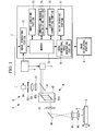
- the fluorescence microscope apparatus 1 is configured based on a laser-scanning microscope.
- the fluorescence microscope apparatus 1 is provided with, as main components, a laser light source (light source) 2 that radiates laser light, a stage 3 on which a specimen A is placed, a irradiation optical system 4 that radiates the laser light from the laser light source 2 onto the specimen A, a detection optical system 5 that detects fluorescence coming from the specimen A, a control unit (focal-position controller and exposure-level controller) 6 that controls positions and exposure levels of the fluorescence detected by the detection optical system 5, an image processing unit 7 that forms an image from the fluorescence detected by the detection optical system 5, and an image displaying portion 8 that displays an image generated by the image processing unit 7.
- a laser light source light source
- stage 3 on which a specimen A is placed
- a irradiation optical system 4 that radiates the laser light from the laser light source 2 onto the specimen A
- a detection optical system 5 that detects fluorescence coming
- the specimen A is, for example, a group of cells.
- a fluorescent substance that specifically binds to cells serving as an observation subject included in the group of cells or that is expressed therein is administered to the group of cells.
- the laser light source 2 emits laser light (excitation light) having an excitation wavelength that excites the fluorescent substance in the specimen A.
- the output intensity of the laser light is controlled by the control unit 6, as described later.
- the stage 3 is provided so as to be movable in an optical-axis direction (Z-direction) of an objective lens 46, described later, and in the two axial directions (XY-directions) that intersect with the optical axis in accordance with control signals from the control unit 6.
- the irradiation optical system 4 is an optical system that radiates laser light from the laser light source 2 onto the specimen A.
- the irradiation optical system 4 is provided with a dichroic mirror 41, a scanning optical unit 42, a relay lens 43, a mirror 44, an imaging lens 45, and the objective lens (objective optical system) 46.
- the objective lens 46 is placed facing the stage 3.
- the objective lens 46 radiates the laser light emitted from the laser light source 2 onto the specimen A on the stage 3 and, also, collects light coming from the specimen A and including fluorescence excited by the laser light.
- the dichroic mirror 41 allows the laser light from the laser light source 2 to pass therethrough and, while reflecting the fluorescence coming from the specimen A collected by the objective lens 46 toward a photodetector 54, described later.
- the scanning optical unit 42 has a pair of galvanometer mirrors 42a and 42b, and changes the swing angles of these galvanometer mirrors 42a and 42b so as to be driven by a raster scanning method. Accordingly, the scanning optical unit 42 scans the laser light from the laser light source 2 on the specimen A in the two axial directions (XY-directions) orthogonal to the optical axis of the objective lens 46.
- the detection optical system 5 is an optical system that detects the fluorescence coming from the specimen A.
- the detection optical system 5 is provided with a photometric filter unit 51, a lens 52, a pinhole 53, and the photodetector (image capturing portion) 54.
- the photometric filter unit 51 allows fluorescence to pass therethrough and blocks light other than the fluorescence (for example, the laser light from the laser light source 2).
- the lens 52 focuses the fluorescence coming from the specimen A, which has passed through the photometric filter unit 51, onto the pinhole 53.
- the pinhole 53 is configured so as to allow only the fluorescence generated at a focal position of the laser light at the specimen A to pass therethrough. Specifically, by passing through the pinhole 53, light coming from positions shifted in the Z-direction from the focal position (measurement point) of the laser light is removed from the fluorescence collected by the objective lens 46. Accordingly, only the fluorescence coming from the same plane as the focal position in the Z-direction enters the photodetector 54.
- the photodetector 54 is, for example, a photomultiplier tube.
- the photodetector 54 photoelectrically converts the detected fluorescence coming from the specimen A and outputs the obtained electric signal to an image generating portion 71 (described later) of the image processing unit 7.
- the control unit 6 causes the laser light source 2, the stage 3, the scanning optical unit 42, and the photodetector 54 to be operated synchronously. Specifically, the control unit 6 moves the focal position of the fluorescence detected by the photodetector 54 in the Z-direction by moving the stage 3 in the Z-direction by a predetermined distance interval. Furthermore, by increasing or decreasing at least one of the detection sensitivity of the photodetector 54, the exposure time of the photodetector 54, and the output intensity of the laser light from the laser light source 2 in a stepwise manner at the individual focal positions, the control unit 6 changes the exposure level of the fluorescence detected by the photodetector 54 in a stepwise manner. Accordingly, the image generating portion 71, described later, generates a plurality of fluorescence images with differing fluorescence exposure levels at the plurality of focal positions.
- the image processing unit 7 is provided with the image generating portion 71, a memory 72, an image combining portion 73, a smoothed-luminance calculating portion 74, a luminance correcting portion 75, a three-dimensional image generating portion 76, and a noise removing portion 77.
- the image generating portion 71 generates a fluorescence image of the specimen A by associating intensities of the fluorescence coming from the specimen A and detected by the photodetector 54 with scanning positions in the XY-directions of the laser light on the specimen A scanned by the scanning optical unit 42. At this time, the image generating portion 71 generates a plurality of fluorescence images with differing fluorescence exposure levels at the plurality of focal positions based on the exposure-level control by the control unit 6. The image generating portion 71 stores the generated fluorescence images in the memory 72 in association with the positions of the stage 3 in the Z-direction at the time of acquiring those fluorescence images.
- the image combining portion 73 generates a combined image by combining the plurality of fluorescence images with different exposure levels, having the same Z-direction position. Specifically, in a fluorescence image having a large light reception level, low-luminance regions in cells serving as observation subjects are clearly displayed, whereas the luminance becomes saturated in high-luminance regions in the cells. In a fluorescence image having a low light reception level, on the other hand, the low-luminance regions of the cells becomes unclear due to a heavy noise interference, whereas the high-luminance regions of the cells are clearly displayed.
- the image combining portion 73 By combining regions in the individual fluorescence images captured at appropriate exposure levels in this way, the image combining portion 73 generates a combined image having an apparently greater dynamic range than the dynamic ranges of the original fluorescence images.
- the image combining portion 73 stores a plurality of the generated combined images in the memory 72.
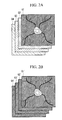
- the widths of the dynamic ranges of the individual combined images, expanded relative to those of the fluorescence images, differ depending on the ranges of luminance distributions in the plurality of original fluorescence images. Accordingly, regions having the same brightness in reality are expressed with a different luminance in each of combined images G1 to G4, as shown in Fig. 2A .
- the smoothed-luminance calculating portion 74 acquires the plurality of combined images stored in the memory 72, and calculates a representative luminance for the individual combined images. It is preferable that the average luminance of the individual combined images be used as the representative luminance. The case in which the average luminance of the individual combined images is used as the representative luminance will be described below. However, for example, the maximum luminance of the individual combined images may be used as the representative luminance instead of the average luminance.
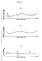
- the average luminance calculated by the smoothed-luminance calculating portion 74 discontinuously changes in the Z-direction due to the variability in the widths of the dynamic ranges of the combined images as described above.
- the smoothed-luminance calculating portion 74 performs smoothing of the average luminance in the Z-direction so as to remove comparatively fine fluctuations in the average luminance while preserving comparatively large fluctuations in the average luminance, thereby calculating smoothed luminance for the individual combined images.
- the smoothed-luminance calculating portion 74 outputs the calculated smoothed luminance of the individual combined images to the luminance correcting portion 75.
- the lateral axis indicates positions of the combined images in the Z-direction and the vertical axis indicates the average luminance.
- a moving average filter calculates an average of average luminances of a predetermined number of combined images that are continuous in the Z-direction centered around a combined image of interest, and sets the calculated average of the average luminance to the luminances of the combined image of interest.
- the luminance correcting portion 75 calculates the differences between the smoothed luminance and average luminance calculated by the smoothed-luminance calculating portion 74 for the individual combined images, and generates corrected images by correcting the luminances of the combined images based on the calculated differences. Specifically, the luminance correcting portion 75 calculates ratios of the calculated differences relative to the smoothed luminance and generates corrected images by increasing or decreasing the luminance of the combined images by amounts corresponding to the calculated ratios. For example, in the case in which the average luminance is larger than the smoothed luminance and the difference therebetween is 20% of the smoothed luminance, a corrected image is generated by decreasing the luminance of the combined image by 20%. The luminance correcting portion 75 stores the generated corrected images in the memory 72.
- the differences between the average luminance and the smoothed luminance are correlated with the comparatively small fluctuations in the average luminance in the combined images.
- the brightnesses thereof relative to the adjacent combined images in the Z-direction show comparatively large differences.
- These brightness differences create a stripe-patterned luminance irregularity in a three-dimensional image. Therefore, by correcting the average luminance of the combined images so as to be equal to the smoothed luminance by using the differences between the average luminance and the smoothed luminance, corrected images G1' to G4' in which the brightness smoothly fluctuates in the Z-direction are obtained, as shown in Fig. 2B .
- the three-dimensional image generating portion 76 acquires the corrected images stored in the memory 72 and generates a three-dimensional image from the acquired corrected images. At this time, the noise removing portion 77 applies a noise removing filter to the individual corrected images before combining them into a three-dimensional image. The three-dimensional image generating portion 76 outputs the three-dimensional image, which is generated from the corrected images subjected to the noise removal, to the image displaying portion 8.
- a bilateral filter is an image processing filter that blurs an image by assigning larger weights to pixels in which luminance differences relative to nearby pixels are small and by assigning smaller weights to pixels in which luminance differences relative to nearby pixels are large.
- the fluorescence microscope apparatus 1 acquires a plurality of fluorescence images needed for generating combined images at a plurality of focal positions. Specifically, laser light emitted from the laser light source 2 is radiated onto a specimen A while the light is scanned two-dimensionally by the scanning optical unit 42. Fluorescent substances are excited at a focal position of the laser light in the specimen A, thus generating fluorescence. After being collected by the objective lens 46, the fluorescence passes through the scanning optical unit 42, is reflected by the dichroic mirror 41, and is detected by the photodetector 54 via the photometric filter unit 51, the lens 52, and the pinhole 53.
- the fluorescence detected by the photodetector 54 is input to the image generating portion 71 of the image processing unit 7 after being photoelectrically converted.
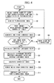
- the image generating portion 71 generates a two-dimensional fluorescence image of the specimen A from the fluorescence intensity information input from the photodetector 54 and the positions where the laser light is scanned by the scanning optical unit 42, input from the control unit 6 (Step S2).
- the fluorescence microscope apparatus 1 performs fluorescence-image acquisition a defined number of times (NO in Step S3) while changing at least one exposure condition among the output intensity of the laser light, the exposure time of the photodetector 54, and the detection sensitivity of the photodetector 54 by means of the control unit 6 (Step S1).
- the image combining portion 73 generates a combined image from these fluorescence images and stores it in the memory 72 (Step S4).
- Step S3 After the acquisition of the defined number of fluorescence images and the combined image generation are completed (YES in Step S3), the fluorescence microscope apparatus 1 moves the stage 3 in the Z-direction by a predetermined distance by means of the control unit 6 (Step S6), and repeats Steps S1 to S4 at different focal positions.
- Step S5 After the acquisition of fluorescence images is completed at all focal positions set in advance (YES in Step S5), the smoothed-luminance calculating portion 74 reads out the combined images from the memory 72, and calculates the smoothed luminance for the individual combined images (Step S7).
- the luminance correcting portion 75 calculates the differences between the average luminance and the smoothed luminance for the individual combined images (Step S8) and generates corrected images by correcting the luminance of the combined images on the basis of the differences (Step S9).
- the three-dimensional image generating portion 76 acquires the corrected images from the memory 72.
- the three-dimensional image generating portion 76 generates a three-dimensional image from these corrected images and outputs it to the image displaying portion 8 (Step S11).
- this embodiment affords an advantage in that, by smoothing the average luminance so that comparatively small fluctuations in the average luminance are removed while preserving comparatively large fluctuations, a conspicuous luminance irregularity can effectively be removed in a three-dimensional image while maintaining nearly optimal contrast in the individual combined images.
- the relative positions of the stage 3 and the objective lens 46 are moved only in the Z-axis direction in this embodiment, alternatively, they may also be moved in the XY-directions.
- the stage 3 is configured to be movable in three axial directions, that is, the XYZ-directions, and the control unit (image-capturing position controller) 6 controls the movement of the stage 3 in the XY-directions.
- the control unit (image-capturing position controller) 6 controls the movement of the stage 3 in the XY-directions.
- Step S1 to S6 the fluorescence microscope apparatus according to this modification is operated similarly to the fluorescence microscope apparatus 1 described above.
- the control unit 6 moves the stage 3 in the XY-directions by predetermined distances (Step S13) and repeats Steps S1 to S6. Thereafter, the control unit 6 repeats moving of the stage 3 in the XY-directions and operations of Steps S1 to S6, and the process advances to Step S7 after the acquisition of the fluorescence images is completed at all set XY-positions (YES in Step S12) .
- the operation of the fluorescence microscope apparatus after Step S7 is the same as that of the fluorescence microscope apparatus 1 described above.
- a three-dimensional image is generated from all combined images having different XY-positions in Step S11 in which the three-dimensional image is generated.
- the image-capturing area is expanded not only in the Z-direction but also in the XY-directions, and thus, three-dimensional images of the specimen A can be obtained in a larger area.
- control unit 6 set exposure conditions for the fluorescence images for each of the XY-positions. Because the distribution of the specimen A and fluorescence intensity differ depending on the XY-positions, if the fluorescence images are acquired under the same exposure conditions at all XY-positions, variability in the luminance also occurs in the XY-directions in the combined images. Therefore, by adjusting the output power, etc. of the laser light source 2 so that fluorescence is captured at the individual XY-positions with substantially equivalent brightness, it is also possible to obtain a three-dimensional image in which the variability in luminance is reduced in the XY-directions.
- a fluorescence microscope apparatus 101 is an epi-illumination or transmission fluorescence microscope (epi-illumination type in the illustrated example), and is provided with a white lamp (light source) 21, such as a mercury lamp, instead of the laser light source 2.
- an illumination optical system 401 is provided with a rotating ND filter 47 and the scanning optical unit 42 is omitted.
- a detection optical system 501 is provided with an image-capturing element 55, such as a CCD, instead of the photodetector 54; a dichroic mirror 56, instead of the mirror 44, which reflects light from the white lamp 21 along the optical axis of the objective lens 46, while allowing fluorescence coming from a specimen A to pass therethrough; and an imaging lens 57 that images the fluorescence, positioned between the dichroic mirror 56 and the image-capturing element 55.
- the rotating ND filter 47 has a plurality of neutral density filters (not shown) and a rotating mechanism (not shown) that rotates the neutral density filters.
- a rotating mechanism that rotates the neutral density filters.
- this modification may be provided with an LED (light source) 22 instead of the white lamp 21.
- LED 22 instead of the white lamp 21.
- the rotating ND filter 47 may be omitted.
- the image processing unit 7 is part of the fluorescence microscope apparatus 1, it is also possible to form the image processing unit 7 as an independent image processing apparatus.
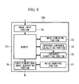
- an image processing apparatus 700 stores these fluorescence images in a memory 721 in association with the information indicating the focal positions therefor, as shown in Fig. 8 .
- the fluorescence images stored in the memory 721 are read out by the image combining portion 73, and combined images are generated.
- the method may be realized by an image processing program that can be executed by a computer.
- the computer is provided with a CPU, a main storage device such as a RAM or the like, and a computer-readable storage medium.
- the computer-readable storage medium stores an image processing program for realizing at least the processing corresponding to Step S4, Steps S7 to S9, and Step S11 among the processing described above.
- the CPU reads out the image processing program stored in the storage medium and executes the image processing and calculations, thereby realizing the same processing as that realized by the image processing apparatus described above.
Landscapes
- Physics & Mathematics (AREA)
- Chemical & Material Sciences (AREA)
- Analytical Chemistry (AREA)
- General Physics & Mathematics (AREA)
- Optics & Photonics (AREA)
- Engineering & Computer Science (AREA)
- Computer Vision & Pattern Recognition (AREA)
- General Engineering & Computer Science (AREA)
- Microscoopes, Condenser (AREA)
- Investigating, Analyzing Materials By Fluorescence Or Luminescence (AREA)
- Image Processing (AREA)
Applications Claiming Priority (1)
| Application Number | Priority Date | Filing Date | Title |
|---|---|---|---|
| JP2011204903A JP5784435B2 (ja) | 2011-09-20 | 2011-09-20 | 画像処理装置、蛍光顕微鏡装置および画像処理プログラム |
Publications (3)
| Publication Number | Publication Date |
|---|---|
| EP2573607A2 true EP2573607A2 (de) | 2013-03-27 |
| EP2573607A3 EP2573607A3 (de) | 2014-01-22 |
| EP2573607B1 EP2573607B1 (de) | 2019-01-09 |
Family
ID=47076012
Family Applications (1)
| Application Number | Title | Priority Date | Filing Date |
|---|---|---|---|
| EP12006571.9A Not-in-force EP2573607B1 (de) | 2011-09-20 | 2012-09-19 | Bildverarbeitungsvorrichtung, Fluoreszenzmikroskopvorrichtung und Bildverarbeitungsprogramm |
Country Status (3)
| Country | Link |
|---|---|
| US (1) | US9279973B2 (de) |
| EP (1) | EP2573607B1 (de) |
| JP (1) | JP5784435B2 (de) |
Cited By (2)
| Publication number | Priority date | Publication date | Assignee | Title |
|---|---|---|---|---|
| US9347852B1 (en) | 2013-05-08 | 2016-05-24 | Thomas DiMatteo | Microscope illumination diagnostic cube |
| WO2021160723A1 (en) * | 2020-02-12 | 2021-08-19 | Universitetet I Oslo | Microscope apparatus |
Families Citing this family (13)
| Publication number | Priority date | Publication date | Assignee | Title |
|---|---|---|---|---|
| DE102013021542A1 (de) * | 2013-12-18 | 2015-06-18 | Carl Zeiss Microscopy Gmbh | Mikroskop und Verfahren zur SPIM Mikroskopie |
| JP2015125177A (ja) * | 2013-12-25 | 2015-07-06 | ソニー株式会社 | 顕微鏡システムおよびその画像データ転送方法 |
| JP6171970B2 (ja) | 2014-02-10 | 2017-08-02 | ソニー株式会社 | レーザ走査型顕微鏡装置および制御方法 |
| JP2016045427A (ja) * | 2014-08-25 | 2016-04-04 | オリンパス株式会社 | 顕微鏡装置 |
| DE102015121403A1 (de) * | 2015-12-09 | 2017-06-14 | Carl Zeiss Microscopy Gmbh | Lichtfeld-bildgebung mit scanoptik |
| US10423819B2 (en) * | 2017-10-31 | 2019-09-24 | Chung Yuan Christian University | Method and apparatus for image processing and visualization for analyzing cell kinematics in cell culture |
| US11042016B2 (en) * | 2017-12-12 | 2021-06-22 | Trustees Of Boston University | Multi-Z confocal imaging system |
| US10757340B2 (en) | 2018-03-09 | 2020-08-25 | Pony Ai Inc. | Adaptive filter system for self-driving vehicle |
| EP4667997A2 (de) | 2018-11-02 | 2025-12-24 | Hologic, Inc. | System und verfahren zur digitalen bildgebung |
| JP6903348B2 (ja) * | 2019-07-09 | 2021-07-14 | 独立行政法人国立文化財機構 | 画像処理装置、画像処理方法およびプログラム |
| KR20240132443A (ko) * | 2021-11-11 | 2024-09-03 | 블랙 라이트 서지컬, 인크. | 조직 특성화를 위한 시스템 및 방법 |
| CN114266817B (zh) * | 2022-03-02 | 2022-06-07 | 广东欧谱曼迪科技有限公司 | 一种荧光深度图像合成方法、装置、电子设备及存储介质 |
| WO2025189030A1 (en) * | 2024-03-07 | 2025-09-12 | Stellaromics, Inc. | Methods and systems for volumetric imaging |
Citations (1)
| Publication number | Priority date | Publication date | Assignee | Title |
|---|---|---|---|---|
| JPH11183803A (ja) | 1997-12-22 | 1999-07-09 | Yokogawa Electric Corp | 共焦点顕微鏡装置 |
Family Cites Families (29)
| Publication number | Priority date | Publication date | Assignee | Title |
|---|---|---|---|---|
| AU4920297A (en) * | 1996-10-25 | 1998-05-15 | Applied Imaging, Inc. | Multifluor-fluorescence in situ hybridization (m-fish) imaging techniques using multiple multiband filters with image registration |
| CA2724743C (fr) * | 2001-06-29 | 2014-11-25 | Universite Libre De Bruxelles | Procede et dispositif destines a l'obtention par microscopie d'images en trois dimensions d'un echantillon |
| WO2003038503A1 (fr) * | 2001-11-02 | 2003-05-08 | Olympus Corporation | Microscope de balayage confocal |
| US20050122577A1 (en) * | 2002-06-18 | 2005-06-09 | Olympus Corporation | Confocal microscope and measuring method by this confocal microscope |
| US20050153356A1 (en) * | 2002-09-09 | 2005-07-14 | Olympus Corporation | Image processing method for biochemical test |
| DE602004031941D1 (de) * | 2003-05-30 | 2011-05-05 | Olympus Co | Messvorrichtung umfassend eine lichtaufnahmeeinheit |
| US7372985B2 (en) * | 2003-08-15 | 2008-05-13 | Massachusetts Institute Of Technology | Systems and methods for volumetric tissue scanning microscopy |
| JP4414722B2 (ja) * | 2003-10-15 | 2010-02-10 | オリンパス株式会社 | レーザー顕微鏡 |
| JP2005275199A (ja) * | 2004-03-26 | 2005-10-06 | Yokogawa Electric Corp | 3次元共焦点顕微鏡システム |
| JP2005284136A (ja) * | 2004-03-30 | 2005-10-13 | Olympus Corp | 観察装置および観察装置の焦点合わせ方法 |
| JP4673000B2 (ja) * | 2004-05-21 | 2011-04-20 | 株式会社キーエンス | 蛍光顕微鏡、蛍光顕微鏡装置を使用した表示方法、蛍光顕微鏡画像表示プログラム及びコンピュータで読み取り可能な記録媒体並びに記憶した機器 |
| US7480421B2 (en) * | 2005-05-23 | 2009-01-20 | Canon Kabushiki Kaisha | Rendering of high dynamic range images |
| JP4865271B2 (ja) * | 2005-08-01 | 2012-02-01 | 株式会社キーエンス | 共焦点走査型顕微鏡 |
| JP4483744B2 (ja) * | 2005-08-26 | 2010-06-16 | ソニー株式会社 | 撮像装置及び撮像制御方法 |
| US8078265B2 (en) * | 2006-07-11 | 2011-12-13 | The General Hospital Corporation | Systems and methods for generating fluorescent light images |
| JP4663602B2 (ja) * | 2006-08-14 | 2011-04-06 | オリンパス株式会社 | 自動合焦装置、顕微鏡および自動合焦方法 |
| US8126205B2 (en) * | 2006-09-25 | 2012-02-28 | Cambridge Research & Instrumentation, Inc. | Sample imaging and classification |
| JP2008170973A (ja) * | 2006-12-13 | 2008-07-24 | Olympus Corp | 共焦点レーザ顕微鏡 |
| WO2009107197A1 (ja) * | 2008-02-26 | 2009-09-03 | 富士通株式会社 | 画像処理装置、画像処理方法および画像処理プログラム |
| JP4937850B2 (ja) * | 2007-07-03 | 2012-05-23 | オリンパス株式会社 | 顕微鏡システム、そのvs画像生成方法、プログラム |
| JP2009033293A (ja) * | 2007-07-25 | 2009-02-12 | Rohm Co Ltd | 画像処理回路、半導体装置、画像処理装置 |
| WO2009029810A1 (en) * | 2007-08-31 | 2009-03-05 | Historx, Inc. | Automatic exposure time selection for imaging tissue |
| US8188412B2 (en) * | 2007-12-27 | 2012-05-29 | Olympus Corporation | Confocal microscope which weights and combines signals output from a plurality of photodetectors and calculates omnifocal brightness information for the plurality of signals |
| US20090238435A1 (en) * | 2008-03-21 | 2009-09-24 | Applied Imaging Corp. | Multi-Exposure Imaging for Automated Fluorescent Microscope Slide Scanning |
| JPWO2010143375A1 (ja) * | 2009-06-10 | 2012-11-22 | 株式会社ニコン | 顕微鏡装置および制御プログラム |
| US8310531B2 (en) * | 2009-08-03 | 2012-11-13 | Genetix Corporation | Methods and apparatuses for processing fluorescence images |
| IN2012DN02337A (de) * | 2009-10-12 | 2015-08-21 | Ventana Med Syst Inc | |
| CN101710131B (zh) * | 2009-12-01 | 2011-06-01 | 西安交通大学 | 离焦数字三维微流场荧光测试仪 |
| JP5136664B2 (ja) * | 2010-07-09 | 2013-02-06 | カシオ計算機株式会社 | 画像処理装置、及びプログラム |
-
2011
- 2011-09-20 JP JP2011204903A patent/JP5784435B2/ja not_active Expired - Fee Related
-
2012
- 2012-09-11 US US13/610,006 patent/US9279973B2/en active Active
- 2012-09-19 EP EP12006571.9A patent/EP2573607B1/de not_active Not-in-force
Patent Citations (1)
| Publication number | Priority date | Publication date | Assignee | Title |
|---|---|---|---|---|
| JPH11183803A (ja) | 1997-12-22 | 1999-07-09 | Yokogawa Electric Corp | 共焦点顕微鏡装置 |
Cited By (2)
| Publication number | Priority date | Publication date | Assignee | Title |
|---|---|---|---|---|
| US9347852B1 (en) | 2013-05-08 | 2016-05-24 | Thomas DiMatteo | Microscope illumination diagnostic cube |
| WO2021160723A1 (en) * | 2020-02-12 | 2021-08-19 | Universitetet I Oslo | Microscope apparatus |
Also Published As
| Publication number | Publication date |
|---|---|
| JP5784435B2 (ja) | 2015-09-24 |
| US9279973B2 (en) | 2016-03-08 |
| EP2573607B1 (de) | 2019-01-09 |
| EP2573607A3 (de) | 2014-01-22 |
| JP2013065266A (ja) | 2013-04-11 |
| US20130070054A1 (en) | 2013-03-21 |
Similar Documents
| Publication | Publication Date | Title |
|---|---|---|
| EP2573607B1 (de) | Bildverarbeitungsvorrichtung, Fluoreszenzmikroskopvorrichtung und Bildverarbeitungsprogramm | |
| US9810895B2 (en) | Biological observation apparatus | |
| US9804376B2 (en) | Scanner with increased dynamic range | |
| US10718715B2 (en) | Microscopy system, microscopy method, and computer-readable storage medium | |
| US8879072B2 (en) | Laser scanning microscope and method for operation thereof | |
| CA3079243C (en) | Image reconstruction method, device and microscopic imaging device | |
| JP2005128086A (ja) | 走査型顕微鏡システム | |
| JP2012237693A (ja) | 画像処理装置、画像処理方法及び画像処理プログラム | |
| JP2013212323A (ja) | 蛍光観察装置および蛍光観察装置の作動方法 | |
| JP2018521360A (ja) | 光学顕微鏡における画像処理のためのシステムおよび方法 | |
| US9055862B2 (en) | Image processing device and image processing method | |
| JP7501364B2 (ja) | 分光イメージング装置および蛍光観察装置 | |
| US7983466B2 (en) | Microscope apparatus and cell observation method | |
| JP2013020204A (ja) | 蛍光顕微鏡装置 | |
| JP6355961B2 (ja) | 標本観察装置 | |
| JP2006293219A (ja) | 走査型共焦点顕微鏡および試料情報測定方法 | |
| US20120141036A1 (en) | Observation apparatus and observation method | |
| JP5669561B2 (ja) | 蛍光観察装置 | |
| JP6257294B2 (ja) | 顕微鏡装置 | |
| EP2458551A2 (de) | Beobachtungsvorrichtung und Beobachtungsverfahren | |
| JP2011237616A (ja) | 走査型顕微鏡 | |
| CN117396749A (zh) | 信息处理方法、信息处理装置及程序 | |
| JP2010102264A (ja) | 顕微鏡 | |
| JP2012002861A (ja) | 走査型顕微鏡 |
Legal Events
| Date | Code | Title | Description |
|---|---|---|---|
| PUAI | Public reference made under article 153(3) epc to a published international application that has entered the european phase |
Free format text: ORIGINAL CODE: 0009012 |
|
| AK | Designated contracting states |
Kind code of ref document: A2 Designated state(s): AL AT BE BG CH CY CZ DE DK EE ES FI FR GB GR HR HU IE IS IT LI LT LU LV MC MK MT NL NO PL PT RO RS SE SI SK SM TR |
|
| AX | Request for extension of the european patent |
Extension state: BA ME |
|
| PUAL | Search report despatched |
Free format text: ORIGINAL CODE: 0009013 |
|
| AK | Designated contracting states |
Kind code of ref document: A3 Designated state(s): AL AT BE BG CH CY CZ DE DK EE ES FI FR GB GR HR HU IE IS IT LI LT LU LV MC MK MT NL NO PL PT RO RS SE SI SK SM TR |
|
| AX | Request for extension of the european patent |
Extension state: BA ME |
|
| RIC1 | Information provided on ipc code assigned before grant |
Ipc: G02B 21/00 20060101AFI20131219BHEP |
|
| 17P | Request for examination filed |
Effective date: 20140721 |
|
| RBV | Designated contracting states (corrected) |
Designated state(s): AL AT BE BG CH CY CZ DE DK EE ES FI FR GB GR HR HU IE IS IT LI LT LU LV MC MK MT NL NO PL PT RO RS SE SI SK SM TR |
|
| RAP1 | Party data changed (applicant data changed or rights of an application transferred) |
Owner name: OLYMPUS CORPORATION |
|
| RAP1 | Party data changed (applicant data changed or rights of an application transferred) |
Owner name: OLYMPUS CORPORATION |
|
| RIN1 | Information on inventor provided before grant (corrected) |
Inventor name: TAKAYA, MOTOHITO |
|
| STAA | Information on the status of an ep patent application or granted ep patent |
Free format text: STATUS: EXAMINATION IS IN PROGRESS |
|
| 17Q | First examination report despatched |
Effective date: 20170321 |
|
| GRAP | Despatch of communication of intention to grant a patent |
Free format text: ORIGINAL CODE: EPIDOSNIGR1 |
|
| STAA | Information on the status of an ep patent application or granted ep patent |
Free format text: STATUS: GRANT OF PATENT IS INTENDED |
|
| INTG | Intention to grant announced |
Effective date: 20180829 |
|
| GRAS | Grant fee paid |
Free format text: ORIGINAL CODE: EPIDOSNIGR3 |
|
| GRAA | (expected) grant |
Free format text: ORIGINAL CODE: 0009210 |
|
| STAA | Information on the status of an ep patent application or granted ep patent |
Free format text: STATUS: THE PATENT HAS BEEN GRANTED |
|
| AK | Designated contracting states |
Kind code of ref document: B1 Designated state(s): AL AT BE BG CH CY CZ DE DK EE ES FI FR GB GR HR HU IE IS IT LI LT LU LV MC MK MT NL NO PL PT RO RS SE SI SK SM TR |
|
| REG | Reference to a national code |
Ref country code: GB Ref legal event code: FG4D |
|
| REG | Reference to a national code |
Ref country code: CH Ref legal event code: EP Ref country code: AT Ref legal event code: REF Ref document number: 1088022 Country of ref document: AT Kind code of ref document: T Effective date: 20190115 |
|
| REG | Reference to a national code |
Ref country code: DE Ref legal event code: R096 Ref document number: 602012055605 Country of ref document: DE |
|
| REG | Reference to a national code |
Ref country code: IE Ref legal event code: FG4D |
|
| REG | Reference to a national code |
Ref country code: NL Ref legal event code: MP Effective date: 20190109 |
|
| REG | Reference to a national code |
Ref country code: LT Ref legal event code: MG4D |
|
| PG25 | Lapsed in a contracting state [announced via postgrant information from national office to epo] |
Ref country code: NL Free format text: LAPSE BECAUSE OF FAILURE TO SUBMIT A TRANSLATION OF THE DESCRIPTION OR TO PAY THE FEE WITHIN THE PRESCRIBED TIME-LIMIT Effective date: 20190109 |
|
| REG | Reference to a national code |
Ref country code: AT Ref legal event code: MK05 Ref document number: 1088022 Country of ref document: AT Kind code of ref document: T Effective date: 20190109 |
|
| PG25 | Lapsed in a contracting state [announced via postgrant information from national office to epo] |
Ref country code: ES Free format text: LAPSE BECAUSE OF FAILURE TO SUBMIT A TRANSLATION OF THE DESCRIPTION OR TO PAY THE FEE WITHIN THE PRESCRIBED TIME-LIMIT Effective date: 20190109 Ref country code: PL Free format text: LAPSE BECAUSE OF FAILURE TO SUBMIT A TRANSLATION OF THE DESCRIPTION OR TO PAY THE FEE WITHIN THE PRESCRIBED TIME-LIMIT Effective date: 20190109 Ref country code: LT Free format text: LAPSE BECAUSE OF FAILURE TO SUBMIT A TRANSLATION OF THE DESCRIPTION OR TO PAY THE FEE WITHIN THE PRESCRIBED TIME-LIMIT Effective date: 20190109 Ref country code: PT Free format text: LAPSE BECAUSE OF FAILURE TO SUBMIT A TRANSLATION OF THE DESCRIPTION OR TO PAY THE FEE WITHIN THE PRESCRIBED TIME-LIMIT Effective date: 20190509 Ref country code: FI Free format text: LAPSE BECAUSE OF FAILURE TO SUBMIT A TRANSLATION OF THE DESCRIPTION OR TO PAY THE FEE WITHIN THE PRESCRIBED TIME-LIMIT Effective date: 20190109 Ref country code: SE Free format text: LAPSE BECAUSE OF FAILURE TO SUBMIT A TRANSLATION OF THE DESCRIPTION OR TO PAY THE FEE WITHIN THE PRESCRIBED TIME-LIMIT Effective date: 20190109 Ref country code: NO Free format text: LAPSE BECAUSE OF FAILURE TO SUBMIT A TRANSLATION OF THE DESCRIPTION OR TO PAY THE FEE WITHIN THE PRESCRIBED TIME-LIMIT Effective date: 20190409 |
|
| PG25 | Lapsed in a contracting state [announced via postgrant information from national office to epo] |
Ref country code: RS Free format text: LAPSE BECAUSE OF FAILURE TO SUBMIT A TRANSLATION OF THE DESCRIPTION OR TO PAY THE FEE WITHIN THE PRESCRIBED TIME-LIMIT Effective date: 20190109 Ref country code: HR Free format text: LAPSE BECAUSE OF FAILURE TO SUBMIT A TRANSLATION OF THE DESCRIPTION OR TO PAY THE FEE WITHIN THE PRESCRIBED TIME-LIMIT Effective date: 20190109 Ref country code: BG Free format text: LAPSE BECAUSE OF FAILURE TO SUBMIT A TRANSLATION OF THE DESCRIPTION OR TO PAY THE FEE WITHIN THE PRESCRIBED TIME-LIMIT Effective date: 20190409 Ref country code: IS Free format text: LAPSE BECAUSE OF FAILURE TO SUBMIT A TRANSLATION OF THE DESCRIPTION OR TO PAY THE FEE WITHIN THE PRESCRIBED TIME-LIMIT Effective date: 20190509 Ref country code: LV Free format text: LAPSE BECAUSE OF FAILURE TO SUBMIT A TRANSLATION OF THE DESCRIPTION OR TO PAY THE FEE WITHIN THE PRESCRIBED TIME-LIMIT Effective date: 20190109 Ref country code: GR Free format text: LAPSE BECAUSE OF FAILURE TO SUBMIT A TRANSLATION OF THE DESCRIPTION OR TO PAY THE FEE WITHIN THE PRESCRIBED TIME-LIMIT Effective date: 20190410 |
|
| REG | Reference to a national code |
Ref country code: DE Ref legal event code: R097 Ref document number: 602012055605 Country of ref document: DE |
|
| PG25 | Lapsed in a contracting state [announced via postgrant information from national office to epo] |
Ref country code: EE Free format text: LAPSE BECAUSE OF FAILURE TO SUBMIT A TRANSLATION OF THE DESCRIPTION OR TO PAY THE FEE WITHIN THE PRESCRIBED TIME-LIMIT Effective date: 20190109 Ref country code: SK Free format text: LAPSE BECAUSE OF FAILURE TO SUBMIT A TRANSLATION OF THE DESCRIPTION OR TO PAY THE FEE WITHIN THE PRESCRIBED TIME-LIMIT Effective date: 20190109 Ref country code: RO Free format text: LAPSE BECAUSE OF FAILURE TO SUBMIT A TRANSLATION OF THE DESCRIPTION OR TO PAY THE FEE WITHIN THE PRESCRIBED TIME-LIMIT Effective date: 20190109 Ref country code: CZ Free format text: LAPSE BECAUSE OF FAILURE TO SUBMIT A TRANSLATION OF THE DESCRIPTION OR TO PAY THE FEE WITHIN THE PRESCRIBED TIME-LIMIT Effective date: 20190109 Ref country code: AL Free format text: LAPSE BECAUSE OF FAILURE TO SUBMIT A TRANSLATION OF THE DESCRIPTION OR TO PAY THE FEE WITHIN THE PRESCRIBED TIME-LIMIT Effective date: 20190109 Ref country code: AT Free format text: LAPSE BECAUSE OF FAILURE TO SUBMIT A TRANSLATION OF THE DESCRIPTION OR TO PAY THE FEE WITHIN THE PRESCRIBED TIME-LIMIT Effective date: 20190109 Ref country code: IT Free format text: LAPSE BECAUSE OF FAILURE TO SUBMIT A TRANSLATION OF THE DESCRIPTION OR TO PAY THE FEE WITHIN THE PRESCRIBED TIME-LIMIT Effective date: 20190109 Ref country code: DK Free format text: LAPSE BECAUSE OF FAILURE TO SUBMIT A TRANSLATION OF THE DESCRIPTION OR TO PAY THE FEE WITHIN THE PRESCRIBED TIME-LIMIT Effective date: 20190109 |
|
| PLBE | No opposition filed within time limit |
Free format text: ORIGINAL CODE: 0009261 |
|
| STAA | Information on the status of an ep patent application or granted ep patent |
Free format text: STATUS: NO OPPOSITION FILED WITHIN TIME LIMIT |
|
| PG25 | Lapsed in a contracting state [announced via postgrant information from national office to epo] |
Ref country code: SM Free format text: LAPSE BECAUSE OF FAILURE TO SUBMIT A TRANSLATION OF THE DESCRIPTION OR TO PAY THE FEE WITHIN THE PRESCRIBED TIME-LIMIT Effective date: 20190109 |
|
| 26N | No opposition filed |
Effective date: 20191010 |
|
| PGFP | Annual fee paid to national office [announced via postgrant information from national office to epo] |
Ref country code: DE Payment date: 20191026 Year of fee payment: 8 |
|
| PG25 | Lapsed in a contracting state [announced via postgrant information from national office to epo] |
Ref country code: SI Free format text: LAPSE BECAUSE OF FAILURE TO SUBMIT A TRANSLATION OF THE DESCRIPTION OR TO PAY THE FEE WITHIN THE PRESCRIBED TIME-LIMIT Effective date: 20190109 |
|
| PG25 | Lapsed in a contracting state [announced via postgrant information from national office to epo] |
Ref country code: TR Free format text: LAPSE BECAUSE OF FAILURE TO SUBMIT A TRANSLATION OF THE DESCRIPTION OR TO PAY THE FEE WITHIN THE PRESCRIBED TIME-LIMIT Effective date: 20190109 |
|
| PG25 | Lapsed in a contracting state [announced via postgrant information from national office to epo] |
Ref country code: MC Free format text: LAPSE BECAUSE OF FAILURE TO SUBMIT A TRANSLATION OF THE DESCRIPTION OR TO PAY THE FEE WITHIN THE PRESCRIBED TIME-LIMIT Effective date: 20190109 |
|
| REG | Reference to a national code |
Ref country code: CH Ref legal event code: PL |
|
| PG25 | Lapsed in a contracting state [announced via postgrant information from national office to epo] |
Ref country code: LI Free format text: LAPSE BECAUSE OF NON-PAYMENT OF DUE FEES Effective date: 20190930 Ref country code: IE Free format text: LAPSE BECAUSE OF NON-PAYMENT OF DUE FEES Effective date: 20190919 Ref country code: LU Free format text: LAPSE BECAUSE OF NON-PAYMENT OF DUE FEES Effective date: 20190919 Ref country code: CH Free format text: LAPSE BECAUSE OF NON-PAYMENT OF DUE FEES Effective date: 20190930 |
|
| REG | Reference to a national code |
Ref country code: BE Ref legal event code: MM Effective date: 20190930 |
|
| PG25 | Lapsed in a contracting state [announced via postgrant information from national office to epo] |
Ref country code: BE Free format text: LAPSE BECAUSE OF NON-PAYMENT OF DUE FEES Effective date: 20190930 |
|
| GBPC | Gb: european patent ceased through non-payment of renewal fee |
Effective date: 20190919 |
|
| PG25 | Lapsed in a contracting state [announced via postgrant information from national office to epo] |
Ref country code: GB Free format text: LAPSE BECAUSE OF NON-PAYMENT OF DUE FEES Effective date: 20190919 Ref country code: FR Free format text: LAPSE BECAUSE OF NON-PAYMENT OF DUE FEES Effective date: 20190930 |
|
| REG | Reference to a national code |
Ref country code: DE Ref legal event code: R119 Ref document number: 602012055605 Country of ref document: DE |
|
| PG25 | Lapsed in a contracting state [announced via postgrant information from national office to epo] |
Ref country code: CY Free format text: LAPSE BECAUSE OF FAILURE TO SUBMIT A TRANSLATION OF THE DESCRIPTION OR TO PAY THE FEE WITHIN THE PRESCRIBED TIME-LIMIT Effective date: 20190109 |
|
| PG25 | Lapsed in a contracting state [announced via postgrant information from national office to epo] |
Ref country code: MT Free format text: LAPSE BECAUSE OF FAILURE TO SUBMIT A TRANSLATION OF THE DESCRIPTION OR TO PAY THE FEE WITHIN THE PRESCRIBED TIME-LIMIT Effective date: 20190109 Ref country code: HU Free format text: LAPSE BECAUSE OF FAILURE TO SUBMIT A TRANSLATION OF THE DESCRIPTION OR TO PAY THE FEE WITHIN THE PRESCRIBED TIME-LIMIT; INVALID AB INITIO Effective date: 20120919 Ref country code: DE Free format text: LAPSE BECAUSE OF NON-PAYMENT OF DUE FEES Effective date: 20210401 |
|
| PG25 | Lapsed in a contracting state [announced via postgrant information from national office to epo] |
Ref country code: MK Free format text: LAPSE BECAUSE OF FAILURE TO SUBMIT A TRANSLATION OF THE DESCRIPTION OR TO PAY THE FEE WITHIN THE PRESCRIBED TIME-LIMIT Effective date: 20190109 |