EP2573162B1 - Culture apparatus provided with heat pipe - Google Patents
Culture apparatus provided with heat pipe Download PDFInfo
- Publication number
- EP2573162B1 EP2573162B1 EP12185470.7A EP12185470A EP2573162B1 EP 2573162 B1 EP2573162 B1 EP 2573162B1 EP 12185470 A EP12185470 A EP 12185470A EP 2573162 B1 EP2573162 B1 EP 2573162B1
- Authority
- EP
- European Patent Office
- Prior art keywords
- heat insulating
- heat
- section
- disposed
- culture apparatus
- Prior art date
- Legal status (The legal status is an assumption and is not a legal conclusion. Google has not performed a legal analysis and makes no representation as to the accuracy of the status listed.)
- Active
Links
- XLYOFNOQVPJJNP-UHFFFAOYSA-N water Substances O XLYOFNOQVPJJNP-UHFFFAOYSA-N 0.000 claims description 34
- 230000017525 heat dissipation Effects 0.000 claims description 15
- 238000005452 bending Methods 0.000 claims description 8
- 239000012212 insulator Substances 0.000 claims description 8
- 229910052751 metal Inorganic materials 0.000 claims description 8
- 239000002184 metal Substances 0.000 claims description 8
- 238000007789 sealing Methods 0.000 claims description 8
- 244000005700 microbiome Species 0.000 claims description 4
- 238000012258 culturing Methods 0.000 claims description 3
- 238000009833 condensation Methods 0.000 description 14
- 230000005494 condensation Effects 0.000 description 14
- 230000000694 effects Effects 0.000 description 8
- 230000002411 adverse Effects 0.000 description 6
- 238000010438 heat treatment Methods 0.000 description 4
- 238000013459 approach Methods 0.000 description 3
- 239000012530 fluid Substances 0.000 description 3
- 238000001514 detection method Methods 0.000 description 2
- 230000005484 gravity Effects 0.000 description 2
- 238000009834 vaporization Methods 0.000 description 2
- 230000008016 vaporization Effects 0.000 description 2
- 241000894006 Bacteria Species 0.000 description 1
- RYGMFSIKBFXOCR-UHFFFAOYSA-N Copper Chemical compound [Cu] RYGMFSIKBFXOCR-UHFFFAOYSA-N 0.000 description 1
- 241001481828 Glyptocephalus cynoglossus Species 0.000 description 1
- BQCADISMDOOEFD-UHFFFAOYSA-N Silver Chemical compound [Ag] BQCADISMDOOEFD-UHFFFAOYSA-N 0.000 description 1
- 229910052782 aluminium Inorganic materials 0.000 description 1
- XAGFODPZIPBFFR-UHFFFAOYSA-N aluminium Chemical compound [Al] XAGFODPZIPBFFR-UHFFFAOYSA-N 0.000 description 1
- 238000001816 cooling Methods 0.000 description 1
- 229910052802 copper Inorganic materials 0.000 description 1
- 239000010949 copper Substances 0.000 description 1
- 238000010586 diagram Methods 0.000 description 1
- 239000008236 heating water Substances 0.000 description 1
- 238000011534 incubation Methods 0.000 description 1
- 239000007788 liquid Substances 0.000 description 1
- 229910052709 silver Inorganic materials 0.000 description 1
- 239000004332 silver Substances 0.000 description 1
- 229910001220 stainless steel Inorganic materials 0.000 description 1
- 239000010935 stainless steel Substances 0.000 description 1
- 239000000758 substrate Substances 0.000 description 1
Images

Classifications
-
- C—CHEMISTRY; METALLURGY
- C12—BIOCHEMISTRY; BEER; SPIRITS; WINE; VINEGAR; MICROBIOLOGY; ENZYMOLOGY; MUTATION OR GENETIC ENGINEERING
- C12M—APPARATUS FOR ENZYMOLOGY OR MICROBIOLOGY; APPARATUS FOR CULTURING MICROORGANISMS FOR PRODUCING BIOMASS, FOR GROWING CELLS OR FOR OBTAINING FERMENTATION OR METABOLIC PRODUCTS, i.e. BIOREACTORS OR FERMENTERS
- C12M41/00—Means for regulation, monitoring, measurement or control, e.g. flow regulation
- C12M41/12—Means for regulation, monitoring, measurement or control, e.g. flow regulation of temperature
- C12M41/18—Heat exchange systems, e.g. heat jackets or outer envelopes
-
- C—CHEMISTRY; METALLURGY
- C12—BIOCHEMISTRY; BEER; SPIRITS; WINE; VINEGAR; MICROBIOLOGY; ENZYMOLOGY; MUTATION OR GENETIC ENGINEERING
- C12M—APPARATUS FOR ENZYMOLOGY OR MICROBIOLOGY; APPARATUS FOR CULTURING MICROORGANISMS FOR PRODUCING BIOMASS, FOR GROWING CELLS OR FOR OBTAINING FERMENTATION OR METABOLIC PRODUCTS, i.e. BIOREACTORS OR FERMENTERS
- C12M23/00—Constructional details, e.g. recesses, hinges
-
- C—CHEMISTRY; METALLURGY
- C12—BIOCHEMISTRY; BEER; SPIRITS; WINE; VINEGAR; MICROBIOLOGY; ENZYMOLOGY; MUTATION OR GENETIC ENGINEERING
- C12M—APPARATUS FOR ENZYMOLOGY OR MICROBIOLOGY; APPARATUS FOR CULTURING MICROORGANISMS FOR PRODUCING BIOMASS, FOR GROWING CELLS OR FOR OBTAINING FERMENTATION OR METABOLIC PRODUCTS, i.e. BIOREACTORS OR FERMENTERS
- C12M41/00—Means for regulation, monitoring, measurement or control, e.g. flow regulation
- C12M41/12—Means for regulation, monitoring, measurement or control, e.g. flow regulation of temperature
- C12M41/14—Incubators; Climatic chambers
-
- C—CHEMISTRY; METALLURGY
- C12—BIOCHEMISTRY; BEER; SPIRITS; WINE; VINEGAR; MICROBIOLOGY; ENZYMOLOGY; MUTATION OR GENETIC ENGINEERING
- C12M—APPARATUS FOR ENZYMOLOGY OR MICROBIOLOGY; APPARATUS FOR CULTURING MICROORGANISMS FOR PRODUCING BIOMASS, FOR GROWING CELLS OR FOR OBTAINING FERMENTATION OR METABOLIC PRODUCTS, i.e. BIOREACTORS OR FERMENTERS
- C12M41/00—Means for regulation, monitoring, measurement or control, e.g. flow regulation
- C12M41/12—Means for regulation, monitoring, measurement or control, e.g. flow regulation of temperature
- C12M41/18—Heat exchange systems, e.g. heat jackets or outer envelopes
- C12M41/24—Heat exchange systems, e.g. heat jackets or outer envelopes inside the vessel
-
- F—MECHANICAL ENGINEERING; LIGHTING; HEATING; WEAPONS; BLASTING
- F25—REFRIGERATION OR COOLING; COMBINED HEATING AND REFRIGERATION SYSTEMS; HEAT PUMP SYSTEMS; MANUFACTURE OR STORAGE OF ICE; LIQUEFACTION SOLIDIFICATION OF GASES
- F25D—REFRIGERATORS; COLD ROOMS; ICE-BOXES; COOLING OR FREEZING APPARATUS NOT OTHERWISE PROVIDED FOR
- F25D21/00—Defrosting; Preventing frosting; Removing condensed or defrost water
- F25D21/14—Collecting or removing condensed and defrost water; Drip trays
-
- F—MECHANICAL ENGINEERING; LIGHTING; HEATING; WEAPONS; BLASTING
- F28—HEAT EXCHANGE IN GENERAL
- F28D—HEAT-EXCHANGE APPARATUS, NOT PROVIDED FOR IN ANOTHER SUBCLASS, IN WHICH THE HEAT-EXCHANGE MEDIA DO NOT COME INTO DIRECT CONTACT
- F28D15/00—Heat-exchange apparatus with the intermediate heat-transfer medium in closed tubes passing into or through the conduit walls ; Heat-exchange apparatus employing intermediate heat-transfer medium or bodies
- F28D15/02—Heat-exchange apparatus with the intermediate heat-transfer medium in closed tubes passing into or through the conduit walls ; Heat-exchange apparatus employing intermediate heat-transfer medium or bodies in which the medium condenses and evaporates, e.g. heat pipes
-
- C—CHEMISTRY; METALLURGY
- C12—BIOCHEMISTRY; BEER; SPIRITS; WINE; VINEGAR; MICROBIOLOGY; ENZYMOLOGY; MUTATION OR GENETIC ENGINEERING
- C12M—APPARATUS FOR ENZYMOLOGY OR MICROBIOLOGY; APPARATUS FOR CULTURING MICROORGANISMS FOR PRODUCING BIOMASS, FOR GROWING CELLS OR FOR OBTAINING FERMENTATION OR METABOLIC PRODUCTS, i.e. BIOREACTORS OR FERMENTERS
- C12M23/00—Constructional details, e.g. recesses, hinges
- C12M23/02—Form or structure of the vessel
-
- C—CHEMISTRY; METALLURGY
- C12—BIOCHEMISTRY; BEER; SPIRITS; WINE; VINEGAR; MICROBIOLOGY; ENZYMOLOGY; MUTATION OR GENETIC ENGINEERING
- C12M—APPARATUS FOR ENZYMOLOGY OR MICROBIOLOGY; APPARATUS FOR CULTURING MICROORGANISMS FOR PRODUCING BIOMASS, FOR GROWING CELLS OR FOR OBTAINING FERMENTATION OR METABOLIC PRODUCTS, i.e. BIOREACTORS OR FERMENTERS
- C12M23/00—Constructional details, e.g. recesses, hinges
- C12M23/40—Manifolds; Distribution pieces
Definitions
- the present invention relates to a culture apparatus provided with a heat pipe.
- a culture apparatus is used to grow a culture such as cells or microorganisms in a culture vessel.
- a culture apparatus is provided with a heater for heating the inside of the culture vessel having a humidifying pan placed therein.
- the culture apparatus is designed such that the heater is controlled to maintain the temperature inside the culture vessel at a prescribed temperature (for example, 37°C) and to maintain the humidity inside the culture vessel at a prescribed humidity (for example, 95%RH) suitable for the prescribed temperature.
- a culture apparatus disclosed in Patent Literature 1 includes a bottom heater for heating water in a humidifying pan, a heater for heating the inside of a culture vessel other than the humidifying pan, and a heater attached to a heat insulating door openably attached to a heat insulating box main body. These three heaters are controlled independently to maintain the temperature of water in the humidifying pan lower than the temperature inside the culture vessel so that supersaturated water in the culture vessel returns to the humidifying pan to thereby suppress dew condensation.
- This culture apparatus includes a temperature sensor for detecting the temperature inside the culture vessel and a temperature sensor for detecting outside air temperature. The above three heaters are controlled independently according to the results of detection by the two temperature sensors.
- Patent Literature 1 Japanese Patent Application Laid-Open No. Hei. 5-227942
- US 2005/084420 A1 relates to an incubator, wherein gas supplied for controlling the gas concentration in an incubation room Is jetted into humidification water.
- US 5 773 287 A discloses an incubator having a means for maintaining the temperature difference between a heatable water tub and a condensate tub.
- the function of a heater is not cooling but heating. Therefore, to maintain the prescribed relation between the temperature of water in the humidifying pan and the temperature inside the culture vessel by controlling these temperatures by using only heaters as described for the culture apparatus disclosed in Patent Literature 1, the temperature sensors are required to have, for example, appropriate detection accuracy.
- the prescribed relation between the two temperatures means that the temperature of water in the humidifying pan is lower than the temperature inside the culture vessel to the extent that the humidity inside the culture vessel can be maintained at a humidity close to a saturated water vapor density while the occurrence of dew condensation at positions where the culture in the culture vessel may be affected is suppressed.
- one problem that must be solved to achieve the prescribed relation is that dew condensation occurs around the humidifying pan because the temperature of the humidifying pan becomes low.
- a heat pipe having a heat input section and a heat dissipation section is attached to a prescribed position of the culture apparatus.
- the heat pipe is designed such that, when the humidity inside the culture vessel approaches, for example, a saturated water vapor density, dew condensation occurs on the heat input section and a heat insulating section in proximity thereto and the condensed water is allowed to flow downward and enter the humidifying pan so that the stored water can be used repeatedly as humidifying water.
- a first aspect of the invention provides a culture apparatus according to claim 1 including: a heat insulating box main body having an opening on a front side thereof; a heat insulating door openably attached to the heat insulating box main body; a transparent inner door that seals the opening in an openable-closable manner; a culture vessel for culturing cells or microorganisms, the culture vessel being surrounded by the inner door and the heat insulating box main body; a duct and a circulation blower that are used to cause forced convection of a gas such as air in the culture vessel; and a humidifying pan disposed on a bottom of the culture vessel and positioned inside the duct, the humidifying pan being configured to store humidifying water used to control humidity inside the culture vessel, wherein the heat insulating box main body includes an outer box made of a metal, an inner box made of a metal, a heat insulator disposed between the outer box and the inner box and on an inner side of the outer box, and an air layer
- the culture apparatus of the first aspect is configured such that the heat insulating section reaching the gas passage in the duct is bent downward at a bending portion such that a portion of the heat pipe that extends from the bending portion to the heat input section is parallel to a corresponding part of the duct.
- the culture apparatus further includes a heat insulating sealing member interposed between the inner box and a portion of the heat insulating section that passes through the inner box.
- the culture apparatus includes: a heat insulating box main body having an opening on a front side thereof; a heat insulating door openably attached to the heat insulating box main body; a transparent inner door that seals the opening in an openable-closable, manner; a culture vessel for culturing cells or microorganisms, the culture vessel being surrounded by the inner door and the heat insulating box main body; a duct and a circulation blower that are used to cause forced convection of a gas such as air in the culture vessel; and a humidifying pan disposed on a bottom of the culture vessel and positioned inside the duct, the humidifying pan being configured to store humidifying water used to control humidity inside the culture vessel, wherein the heat insulating box main body includes an outer box made of a metal, an inner box made of a metal, a heat insulator disposed between the outer box and the inner box and on an inner side of the outer box, and an air layer disposed on an inner side of the heat insul
- the culture apparatus further includes a heat pipe having a heat insulating section, a heat input section disposed at one end of the heat insulating section, and a heat dissipation section disposed at the other end of the heat insulating section, the heat pipe being attached to the culture apparatus with the heat dissipation section being disposed outside the culture apparatus, the heat insulating section being disposed passing through the heat insulating box main body and the inner box, and the heat input section being disposed in a gas passage in the duct, so that water condensed on the heat input section and the heat insulating section in proximity thereto flows downward and enters the humidifying pan and can be repeatedly used as the humidifying water.
- This culture apparatus is configured such that the heat pipe having the heat input section and the heat dissipation section is attached to a prescribed position of the culture apparatus, and when the humidity inside the culture vessel approaches a saturated water vapor density, dew condensation occurs on the heat input section, and the condensed water flows downward, enters the humidifying pan, and can be repeatedly used as the humidifying water. Therefore, the culture apparatus provided has the following advantageous effects: dew condensation is prevented, and adverse effects on the culture are thereby suppressed; the culture apparatus can be operated with the circulation blower in the duct being operated so that unevenness in temperature and humidity inside the culture vessel is prevented; and the culture apparatus can be produced at low cost and is economic.
- the culture apparatus is configured such that the heat insulating section reaching the gas passage in the duct is bent downward at a bending portion such that a portion of the heat pipe that extends from the bending portion to the heat input section is parallel to a corresponding part of the duct.
- this culture apparatus has a further advantageous effect in that dew condensation occurs on the portion of the heat pipe that extends from the bending portion to the heat input section and the condensed water flows downward by gravity and enters the humidifying pan without being splattered.
- the culture apparatus further includes a heat insulating sealing member interposed between the inner box and a portion of the heat insulating section that passes through the inner box. Therefore, this culture apparatus has a further advantageous effect in that, since the heat insulating sealing member is interposed between the inner box and the heat insulating section of the heat pipe, the gas flowing through the gas passage is prevented from leaking, so that the culture vessel is not adversely affected and dew condensation is prevented from occurring on the contact portion between the heat insulating section and the inner box.
- a culture apparatus 1 in the embodiment of the present invention includes doors that open from the right (more specifically, an outer door and an inner door) and small double doors as shown in FIGs. 1 and 2 .
- a culture vessel 4 is formed as a space surrounded by a heat insulating box main body 2 having an opening 2A on its front side and a transparent door 3 used as an inner door that can seal the opening 2A in an openable-closable manner.
- the left side of the transparent door 3 is hinged to the heat insulating box main body 2 in an openable-closable manner, and the transparent door 3 can hermetically seal the opening 2A through a gasket 2B disposed on an opening portion of the culture vessel 4.
- the sealing member (gasket) 2B for sealing the transparent inner door 3 and the heat insulating box main body 2 is disposed on the opening of the culture vessel 4.
- the inside of the culture vessel 4 is vertically partitioned by a plurality of shelves 5 (into 5 sections by 4 shelves in this embodiment).
- the concentration of CO 2 is often set to and maintained at about 5%, and CO 2 gas is supplied to the inside of the culture vessel 4 to control the concentration of CO 2 after the doors are closed. Therefore, a plurality of pairs of small double doors 6A and 6B for the plurality of partitioned sections (5 pairs in this embodiment) are provided on the inner side of the inner door 3 so that outside air is prevented from entering the entire culture vessel 4 partitioned into the partitioned sections even when the inner door 3 is opened.
- Reference numeral 7 represents a heat insulating door serving as an outer door hinged to the heat insulating box main body 2 in an openable-closable manner and used to prevent heat from entering from the opening 2A of the culture vessel 4, and a gasket 8 with a magnet is provided on the rear circumference of the heat insulating door 7.
- a duct 11 composed of a rear-side duct 11A and a bottom duct 11B is disposed on the rear side and the bottom of the culture vessel 4 so as to form a space for a gas passage K for CO 2 etc.
- a gas such as CO 2 in the culture vessel 4 is drawn from an inlet port 12 formed in the upper part of the rear duct 11A and is blown out into the culture vessel 4 from an outlet port 13 disposed over the front and side surfaces of the bottom duct 11B, so that the gas is forcibly circulated.
- a circulation blower 14 is disposed inside the duct 11 (in the upper part thereof in this embodiment) to forcibly circulate the gas such as CO 2 .
- the blower 14 is composed of a fan, a motor, and a shaft.
- the motor is disposed in a machine room 19 (described later) on the outer rear side of the culture vessel 4, and the shaft extends from the motor in the machine room 19, passes through the rear surface of the heat insulating box main body 2, reaches the gas passage K for CO 2 etc., and is connected to the fan.
- a humidifying pan 15 for storing humidifying water 16 (i.e., water used for humidification) is disposed on the bottom of the culture vessel 4 and positioned in the duct 11.
- the humidifying pan 15 is heated by a heater 32 disposed on the outer bottom side of an inner box 22 made of a metal (for example, stainless steel), and the water thereby evaporates.
- a humidified gas in the gas passage K for CO 2 etc. that is composed of the circulation blower 14 and the duct 11 can be more efficiently blown out into the culture vessel 4.
- the motor serving as means for driving the circulation blower 14, gas supply means 17 for supplying CO 2 gas to the culture vessel 4, and the machine room 19 used to dispose electric components such as a control substrate (not shown) are formed on the rear side of an outer box 21 of the heat insulating box main body 2.
- the gas supply means 17 includes a gas supply tube 17A, an on-off valve 17B, a filter 17C, etc., and the end portion of the gas supply tube 17A is positioned in the gas passage K.
- the CO 2 gas supplied from the gas supply tube 17A can be injected into the culture vessel 4.
- the heat insulating box main body 2 includes the metal-made outer box 21, the stainless steel-made inner box 22, a heat insulator 24 disposed between the outer box 21 and the inner box 22 and positioned on the inner side of the outer box 21, and an air layer (so-called air jacket) 25 disposed on the inner side of the heat insulator 24.
- Heaters (not shown) for heating the culture vessel are disposed on the left and right, side-surfaces and top and rear surfaces of the inner box 22 forming the culture vessel 4.
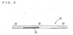
- a heat pipe 35 having a heat insulating section 30, a heat input section 31 disposed at one end of the heat insulating section 30, and a heat dissipation section 32 disposed at the other end of the heat insulating section 30 is attached to a prescribed position of the culture apparatus 1 as shown in FIG. 2 .
- the heat pipe 35 is attached such that the heat dissipation section 32 of the heat pipe 35 is disposed outside the culture apparatus 1, that the heat insulating section 30 is disposed to pass through the heat insulating box main body 2 and the inner box 22, and that the heat input section 31 is disposed in the gas passage K inside the duct 11A.
- the heat pipe 35 has a bent section 34 formed by bending downward the heat insulating section 30 reaching the gas passage K in the duct 11A, and a portion of the heat pipe 35 that extends from the bent section 34 to the heat input section 31 is configured to be parallel to a corresponding part of the duct 11A.
- Dew condensation occurs mainly on this portion of the heat pipe 35 that extends from the bent section 34 to the heat input section 31, and the condensed water flows downward by gravity and enters the humidifying pan 15 without being splattered.
- the heat insulating section 30 is disposed with a heat insulating sealing member 36 interposed between the inner box 22 and a portion of the heat insulating section 30 that passes through the inner box 22.
- the heat insulating sealing member 36 Since the heat insulating sealing member 36 is interposed, the gas flowing through the gas passage K is prevented from leaking. Therefore, the culture vessel 4 is not adversely affected, and dew condensation is prevented from occurring on the contact portion between the heat insulating section 30 and the inner box 22.
- the heat pipe used in the invention includes a sealed vessel containing a small amount of liquid (operating fluid) vacuum sealed therein, and a capillarity structure (wick) 33 is provided on the inner wall of the heat pipe.
- the operating fluid evaporates in the heat input section 31 (absorbs the latent heat of vaporization), and the generated vapor moves toward the heat dissipation section 32.
- the vapor is condensed in the heat dissipation section 32 and releases the latent heat of vaporization.
- the condensed fluid is refluxed by capillarity in the heat input section 31. A series of phase changes occurs continuously, and the heat is thereby transferred rapidly.
- a commercial heat pipe and a metal rod of copper, aluminum, silver, etc. can also be used.
- a heat sink for improving heat dissipation or a heater for maintaining the temperature of the heat pipe appropriately may be attached to the heat dissipation section 32 of the heat pipe.
- the volume, shape, dimensions, number, etc. of the heat pipe used in the invention vary depending on the volume, shape, size, etc. of the culture apparatus and the culture to be grown.
- the heat pipe having the heat input section and the heat dissipation section is attached to a prescribed position.
- the humidity inside the culture vessel approaches, for example, a saturated water vapor density
- dew condensation occurs on the heat input section, and the condensed water flows downward, enters the humidifying pan, and can be repeatedly used as humidifying water. Therefore, the culture apparatus provided has the following advantageous effects: dew condensation is prevented, and adverse effects on the culture are thereby suppressed; the culture apparatus can be operated with the circulation blower in the duct being operated so that unevenness in temperature and humidity inside the culture vessel is prevented; and the culture apparatus can be produced at low cost and is economic. Therefore, the industrial applicability of the culture apparatus is significantly high.
Landscapes
- Engineering & Computer Science (AREA)
- Chemical & Material Sciences (AREA)
- Health & Medical Sciences (AREA)
- Life Sciences & Earth Sciences (AREA)
- Wood Science & Technology (AREA)
- Bioinformatics & Cheminformatics (AREA)
- Organic Chemistry (AREA)
- Zoology (AREA)
- General Engineering & Computer Science (AREA)
- Physics & Mathematics (AREA)
- Thermal Sciences (AREA)
- Sustainable Development (AREA)
- Biotechnology (AREA)
- Microbiology (AREA)
- Biochemistry (AREA)
- General Health & Medical Sciences (AREA)
- Genetics & Genomics (AREA)
- Biomedical Technology (AREA)
- Analytical Chemistry (AREA)
- Mechanical Engineering (AREA)
- Clinical Laboratory Science (AREA)
- Combustion & Propulsion (AREA)
- Apparatus Associated With Microorganisms And Enzymes (AREA)
- Chemical Kinetics & Catalysis (AREA)
Applications Claiming Priority (1)
| Application Number | Priority Date | Filing Date | Title |
|---|---|---|---|
| JP2011207836A JP5908240B2 (ja) | 2011-09-22 | 2011-09-22 | 培養装置 |
Publications (2)
| Publication Number | Publication Date |
|---|---|
| EP2573162A1 EP2573162A1 (en) | 2013-03-27 |
| EP2573162B1 true EP2573162B1 (en) | 2016-08-10 |
Family
ID=47010257
Family Applications (1)
| Application Number | Title | Priority Date | Filing Date |
|---|---|---|---|
| EP12185470.7A Active EP2573162B1 (en) | 2011-09-22 | 2012-09-21 | Culture apparatus provided with heat pipe |
Country Status (3)
| Country | Link |
|---|---|
| US (2) | US8815579B2 (ja) |
| EP (1) | EP2573162B1 (ja) |
| JP (1) | JP5908240B2 (ja) |
Cited By (1)
| Publication number | Priority date | Publication date | Assignee | Title |
|---|---|---|---|---|
| CN108531388A (zh) * | 2017-03-03 | 2018-09-14 | 阿道夫科耐公司 | 用于对恒温箱进行加湿的方法和恒温箱 |
Families Citing this family (21)
| Publication number | Priority date | Publication date | Assignee | Title |
|---|---|---|---|---|
| CN105073973B (zh) * | 2013-03-22 | 2018-12-28 | 普和希控股公司 | 培养装置 |
| CN105051175B (zh) * | 2013-03-22 | 2016-11-23 | 松下健康医疗控股株式会社 | 培养装置 |
| DE102013013665B4 (de) * | 2013-08-16 | 2015-12-03 | Thermo Electron Led Gmbh | Laboratoriumsbrutschrank mit verbesserter Feuchtigkeitseinstellung |
| EP3031902B1 (en) * | 2013-10-11 | 2017-12-06 | Panasonic Healthcare Holdings Co., Ltd. | Culture apparatus |
| CN105555944B (zh) | 2013-10-11 | 2017-03-15 | 松下健康医疗控股株式会社 | 培养装置 |
| CN105531361A (zh) * | 2013-10-11 | 2016-04-27 | 松下健康医疗控股株式会社 | 培养装置 |
| CN103651085B (zh) * | 2013-11-26 | 2016-04-06 | 魏延恕 | 一种电动推拉自动收放型无土栽培装置 |
| CN103667048B (zh) * | 2014-01-08 | 2015-03-18 | 中国人民解放军疾病预防控制所 | 一种便携式微生物培养箱 |
| WO2015111544A1 (ja) * | 2014-01-24 | 2015-07-30 | パナソニックヘルスケア株式会社 | インキュベータおよびこれを備えた細胞培養システム、加湿水の供給方法 |
| JP6401987B2 (ja) * | 2014-09-22 | 2018-10-10 | Phcホールディングス株式会社 | 培養装置及び湿度制御方法 |
| CN107208017A (zh) * | 2015-02-05 | 2017-09-26 | 奥林巴斯株式会社 | 细胞培养装置 |
| WO2017169850A1 (ja) * | 2016-03-28 | 2017-10-05 | パナソニックヘルスケアホールディングス株式会社 | 培養装置及び培養装置の制御方法 |
| CN107914969B (zh) * | 2017-12-29 | 2018-12-14 | 崔洋 | 生物标本存放用装置 |
| CN108546635B (zh) * | 2018-05-17 | 2021-10-15 | 董建凯 | 一种医疗电热培养箱 |
| EP3828259B1 (en) * | 2018-09-06 | 2023-11-22 | PHC Corporation | Culture device |
| DE102019121639A1 (de) * | 2019-08-12 | 2021-02-18 | Adolf Kühner Ag | Wasserbad zum Befeuchten eines Innenraums eines Inkubators |
| CN111117882A (zh) * | 2020-03-10 | 2020-05-08 | 广西贵港华堂天诺微生物科技有限公司 | 一种微生物恒温培养装置 |
| CN112023988B (zh) * | 2020-09-07 | 2022-04-29 | 深圳比特微电子科技有限公司 | 电子产品的恒温测试箱 |
| CN114134034B (zh) * | 2021-12-08 | 2023-12-19 | 广东三木科技有限公司 | 一种防冷凝水的微生物培养用恒温箱 |
| WO2023145694A1 (ja) * | 2022-01-26 | 2023-08-03 | Phcホールディングス株式会社 | 培養装置 |
| CN117660160B (zh) * | 2023-12-05 | 2024-08-16 | 山东大学 | 一种独立分层式培养箱 |
Family Cites Families (8)
| Publication number | Priority date | Publication date | Assignee | Title |
|---|---|---|---|---|
| JPS62202199U (ja) * | 1986-06-12 | 1987-12-23 | ||
| JPH05227942A (ja) | 1992-02-25 | 1993-09-07 | Unie Data:Kk | 培養装置 |
| DE4441250C1 (de) * | 1994-11-19 | 1996-04-25 | Binder Peter Michael | Brutschrank |
| US6302944B1 (en) * | 1999-04-23 | 2001-10-16 | Stuart Alfred Hoenig | Apparatus for extracting water vapor from air |
| JP2005095097A (ja) * | 2003-09-26 | 2005-04-14 | Sanyo Electric Co Ltd | 培養庫 |
| JP2005118021A (ja) * | 2003-10-20 | 2005-05-12 | Sanyo Electric Co Ltd | 培養庫 |
| JP5017133B2 (ja) * | 2008-01-30 | 2012-09-05 | 三洋電機株式会社 | 恒温装置およびカバー |
| JP5570191B2 (ja) * | 2009-11-30 | 2014-08-13 | パナソニックヘルスケア株式会社 | インキュベータ |
-
2011
- 2011-09-22 JP JP2011207836A patent/JP5908240B2/ja active Active
-
2012
- 2012-09-21 EP EP12185470.7A patent/EP2573162B1/en active Active
- 2012-09-21 US US13/624,716 patent/US8815579B2/en active Active
-
2014
- 2014-07-21 US US14/336,809 patent/US9506026B2/en active Active
Cited By (1)
| Publication number | Priority date | Publication date | Assignee | Title |
|---|---|---|---|---|
| CN108531388A (zh) * | 2017-03-03 | 2018-09-14 | 阿道夫科耐公司 | 用于对恒温箱进行加湿的方法和恒温箱 |
Also Published As
| Publication number | Publication date |
|---|---|
| US9506026B2 (en) | 2016-11-29 |
| US20140331707A1 (en) | 2014-11-13 |
| EP2573162A1 (en) | 2013-03-27 |
| JP2013066435A (ja) | 2013-04-18 |
| US20130078714A1 (en) | 2013-03-28 |
| JP5908240B2 (ja) | 2016-04-26 |
| US8815579B2 (en) | 2014-08-26 |
Similar Documents
| Publication | Publication Date | Title |
|---|---|---|
| EP2573162B1 (en) | Culture apparatus provided with heat pipe | |
| JP5897855B2 (ja) | ヒーターを備えた培養装置 | |
| EP2963106B1 (en) | Culture apparatus | |
| KR100998833B1 (ko) | 배양고 | |
| EP2692851B1 (en) | Sensor unit with incubator | |
| US11098277B2 (en) | Culture apparatus and method of controlling culture apparatus | |
| US10704020B2 (en) | Incubator | |
| US20210189318A1 (en) | Culture device | |
| JP5887022B2 (ja) | 培養装置 | |
| JP6666768B2 (ja) | 培養装置 | |
| EP3561039B1 (en) | Accommodation device | |
| CN216432302U (zh) | 一种聚酰亚胺膜实验用氮气保护真空烘箱 | |
| JP2005351563A (ja) | 蒸気調理器 | |
| JP2004222731A (ja) | 培養装置 | |
| JP4550033B2 (ja) | 蒸気調理器 | |
| JP4405319B2 (ja) | 蒸気調理器 |
Legal Events
| Date | Code | Title | Description |
|---|---|---|---|
| PUAI | Public reference made under article 153(3) epc to a published international application that has entered the european phase |
Free format text: ORIGINAL CODE: 0009012 |
|
| AK | Designated contracting states |
Kind code of ref document: A1 Designated state(s): AL AT BE BG CH CY CZ DE DK EE ES FI FR GB GR HR HU IE IS IT LI LT LU LV MC MK MT NL NO PL PT RO RS SE SI SK SM TR |
|
| AX | Request for extension of the european patent |
Extension state: BA ME |
|
| 17P | Request for examination filed |
Effective date: 20130612 |
|
| RBV | Designated contracting states (corrected) |
Designated state(s): AL AT BE BG CH CY CZ DE DK EE ES FI FR GB GR HR HU IE IS IT LI LT LU LV MC MK MT NL NO PL PT RO RS SE SI SK SM TR |
|
| GRAP | Despatch of communication of intention to grant a patent |
Free format text: ORIGINAL CODE: EPIDOSNIGR1 |
|
| RIC1 | Information provided on ipc code assigned before grant |
Ipc: F25D 21/14 20060101ALI20160203BHEP Ipc: F28D 15/02 20060101ALI20160203BHEP Ipc: B01L 1/00 20060101ALI20160203BHEP Ipc: C12M 1/00 20060101AFI20160203BHEP |
|
| INTG | Intention to grant announced |
Effective date: 20160219 |
|
| GRAS | Grant fee paid |
Free format text: ORIGINAL CODE: EPIDOSNIGR3 |
|
| GRAA | (expected) grant |
Free format text: ORIGINAL CODE: 0009210 |
|
| RAP1 | Party data changed (applicant data changed or rights of an application transferred) |
Owner name: PANASONIC HEALTHCARE HOLDINGS CO., LTD. |
|
| AK | Designated contracting states |
Kind code of ref document: B1 Designated state(s): AL AT BE BG CH CY CZ DE DK EE ES FI FR GB GR HR HU IE IS IT LI LT LU LV MC MK MT NL NO PL PT RO RS SE SI SK SM TR |
|
| REG | Reference to a national code |
Ref country code: GB Ref legal event code: FG4D |
|
| REG | Reference to a national code |
Ref country code: CH Ref legal event code: EP Ref country code: AT Ref legal event code: REF Ref document number: 819064 Country of ref document: AT Kind code of ref document: T Effective date: 20160815 |
|
| REG | Reference to a national code |
Ref country code: IE Ref legal event code: FG4D |
|
| REG | Reference to a national code |
Ref country code: FR Ref legal event code: PLFP Year of fee payment: 5 |
|
| REG | Reference to a national code |
Ref country code: DE Ref legal event code: R096 Ref document number: 602012021412 Country of ref document: DE |
|
| REG | Reference to a national code |
Ref country code: NL Ref legal event code: FP |
|
| REG | Reference to a national code |
Ref country code: LT Ref legal event code: MG4D |
|
| REG | Reference to a national code |
Ref country code: AT Ref legal event code: MK05 Ref document number: 819064 Country of ref document: AT Kind code of ref document: T Effective date: 20160810 |
|
| PG25 | Lapsed in a contracting state [announced via postgrant information from national office to epo] |
Ref country code: FI Free format text: LAPSE BECAUSE OF FAILURE TO SUBMIT A TRANSLATION OF THE DESCRIPTION OR TO PAY THE FEE WITHIN THE PRESCRIBED TIME-LIMIT Effective date: 20160810 Ref country code: LT Free format text: LAPSE BECAUSE OF FAILURE TO SUBMIT A TRANSLATION OF THE DESCRIPTION OR TO PAY THE FEE WITHIN THE PRESCRIBED TIME-LIMIT Effective date: 20160810 Ref country code: IS Free format text: LAPSE BECAUSE OF FAILURE TO SUBMIT A TRANSLATION OF THE DESCRIPTION OR TO PAY THE FEE WITHIN THE PRESCRIBED TIME-LIMIT Effective date: 20161210 Ref country code: IT Free format text: LAPSE BECAUSE OF FAILURE TO SUBMIT A TRANSLATION OF THE DESCRIPTION OR TO PAY THE FEE WITHIN THE PRESCRIBED TIME-LIMIT Effective date: 20160810 Ref country code: NO Free format text: LAPSE BECAUSE OF FAILURE TO SUBMIT A TRANSLATION OF THE DESCRIPTION OR TO PAY THE FEE WITHIN THE PRESCRIBED TIME-LIMIT Effective date: 20161110 Ref country code: RS Free format text: LAPSE BECAUSE OF FAILURE TO SUBMIT A TRANSLATION OF THE DESCRIPTION OR TO PAY THE FEE WITHIN THE PRESCRIBED TIME-LIMIT Effective date: 20160810 Ref country code: HR Free format text: LAPSE BECAUSE OF FAILURE TO SUBMIT A TRANSLATION OF THE DESCRIPTION OR TO PAY THE FEE WITHIN THE PRESCRIBED TIME-LIMIT Effective date: 20160810 |
|
| PG25 | Lapsed in a contracting state [announced via postgrant information from national office to epo] |
Ref country code: GR Free format text: LAPSE BECAUSE OF FAILURE TO SUBMIT A TRANSLATION OF THE DESCRIPTION OR TO PAY THE FEE WITHIN THE PRESCRIBED TIME-LIMIT Effective date: 20161111 Ref country code: AT Free format text: LAPSE BECAUSE OF FAILURE TO SUBMIT A TRANSLATION OF THE DESCRIPTION OR TO PAY THE FEE WITHIN THE PRESCRIBED TIME-LIMIT Effective date: 20160810 Ref country code: BE Free format text: LAPSE BECAUSE OF NON-PAYMENT OF DUE FEES Effective date: 20160930 Ref country code: LV Free format text: LAPSE BECAUSE OF FAILURE TO SUBMIT A TRANSLATION OF THE DESCRIPTION OR TO PAY THE FEE WITHIN THE PRESCRIBED TIME-LIMIT Effective date: 20160810 Ref country code: SE Free format text: LAPSE BECAUSE OF FAILURE TO SUBMIT A TRANSLATION OF THE DESCRIPTION OR TO PAY THE FEE WITHIN THE PRESCRIBED TIME-LIMIT Effective date: 20160810 Ref country code: PL Free format text: LAPSE BECAUSE OF FAILURE TO SUBMIT A TRANSLATION OF THE DESCRIPTION OR TO PAY THE FEE WITHIN THE PRESCRIBED TIME-LIMIT Effective date: 20160810 Ref country code: ES Free format text: LAPSE BECAUSE OF FAILURE TO SUBMIT A TRANSLATION OF THE DESCRIPTION OR TO PAY THE FEE WITHIN THE PRESCRIBED TIME-LIMIT Effective date: 20160810 Ref country code: PT Free format text: LAPSE BECAUSE OF FAILURE TO SUBMIT A TRANSLATION OF THE DESCRIPTION OR TO PAY THE FEE WITHIN THE PRESCRIBED TIME-LIMIT Effective date: 20161212 |
|
| PG25 | Lapsed in a contracting state [announced via postgrant information from national office to epo] |
Ref country code: RO Free format text: LAPSE BECAUSE OF FAILURE TO SUBMIT A TRANSLATION OF THE DESCRIPTION OR TO PAY THE FEE WITHIN THE PRESCRIBED TIME-LIMIT Effective date: 20160810 Ref country code: EE Free format text: LAPSE BECAUSE OF FAILURE TO SUBMIT A TRANSLATION OF THE DESCRIPTION OR TO PAY THE FEE WITHIN THE PRESCRIBED TIME-LIMIT Effective date: 20160810 |
|
| REG | Reference to a national code |
Ref country code: CH Ref legal event code: PL |
|
| REG | Reference to a national code |
Ref country code: DE Ref legal event code: R097 Ref document number: 602012021412 Country of ref document: DE |
|
| PG25 | Lapsed in a contracting state [announced via postgrant information from national office to epo] |
Ref country code: CZ Free format text: LAPSE BECAUSE OF FAILURE TO SUBMIT A TRANSLATION OF THE DESCRIPTION OR TO PAY THE FEE WITHIN THE PRESCRIBED TIME-LIMIT Effective date: 20160810 Ref country code: SK Free format text: LAPSE BECAUSE OF FAILURE TO SUBMIT A TRANSLATION OF THE DESCRIPTION OR TO PAY THE FEE WITHIN THE PRESCRIBED TIME-LIMIT Effective date: 20160810 Ref country code: BE Free format text: LAPSE BECAUSE OF FAILURE TO SUBMIT A TRANSLATION OF THE DESCRIPTION OR TO PAY THE FEE WITHIN THE PRESCRIBED TIME-LIMIT Effective date: 20160810 Ref country code: DK Free format text: LAPSE BECAUSE OF FAILURE TO SUBMIT A TRANSLATION OF THE DESCRIPTION OR TO PAY THE FEE WITHIN THE PRESCRIBED TIME-LIMIT Effective date: 20160810 Ref country code: BG Free format text: LAPSE BECAUSE OF FAILURE TO SUBMIT A TRANSLATION OF THE DESCRIPTION OR TO PAY THE FEE WITHIN THE PRESCRIBED TIME-LIMIT Effective date: 20161110 Ref country code: SM Free format text: LAPSE BECAUSE OF FAILURE TO SUBMIT A TRANSLATION OF THE DESCRIPTION OR TO PAY THE FEE WITHIN THE PRESCRIBED TIME-LIMIT Effective date: 20160810 |
|
| PLBE | No opposition filed within time limit |
Free format text: ORIGINAL CODE: 0009261 |
|
| STAA | Information on the status of an ep patent application or granted ep patent |
Free format text: STATUS: NO OPPOSITION FILED WITHIN TIME LIMIT |
|
| REG | Reference to a national code |
Ref country code: IE Ref legal event code: MM4A |
|
| PG25 | Lapsed in a contracting state [announced via postgrant information from national office to epo] |
Ref country code: MC Free format text: LAPSE BECAUSE OF FAILURE TO SUBMIT A TRANSLATION OF THE DESCRIPTION OR TO PAY THE FEE WITHIN THE PRESCRIBED TIME-LIMIT Effective date: 20160810 |
|
| 26N | No opposition filed |
Effective date: 20170511 |
|
| PG25 | Lapsed in a contracting state [announced via postgrant information from national office to epo] |
Ref country code: LI Free format text: LAPSE BECAUSE OF NON-PAYMENT OF DUE FEES Effective date: 20160930 Ref country code: CH Free format text: LAPSE BECAUSE OF NON-PAYMENT OF DUE FEES Effective date: 20160930 Ref country code: IE Free format text: LAPSE BECAUSE OF NON-PAYMENT OF DUE FEES Effective date: 20160921 |
|
| REG | Reference to a national code |
Ref country code: FR Ref legal event code: PLFP Year of fee payment: 6 |
|
| PG25 | Lapsed in a contracting state [announced via postgrant information from national office to epo] |
Ref country code: LU Free format text: LAPSE BECAUSE OF NON-PAYMENT OF DUE FEES Effective date: 20160921 Ref country code: SI Free format text: LAPSE BECAUSE OF FAILURE TO SUBMIT A TRANSLATION OF THE DESCRIPTION OR TO PAY THE FEE WITHIN THE PRESCRIBED TIME-LIMIT Effective date: 20160810 |
|
| PG25 | Lapsed in a contracting state [announced via postgrant information from national office to epo] |
Ref country code: HU Free format text: LAPSE BECAUSE OF FAILURE TO SUBMIT A TRANSLATION OF THE DESCRIPTION OR TO PAY THE FEE WITHIN THE PRESCRIBED TIME-LIMIT; INVALID AB INITIO Effective date: 20120921 Ref country code: CY Free format text: LAPSE BECAUSE OF FAILURE TO SUBMIT A TRANSLATION OF THE DESCRIPTION OR TO PAY THE FEE WITHIN THE PRESCRIBED TIME-LIMIT Effective date: 20160810 |
|
| PG25 | Lapsed in a contracting state [announced via postgrant information from national office to epo] |
Ref country code: MK Free format text: LAPSE BECAUSE OF FAILURE TO SUBMIT A TRANSLATION OF THE DESCRIPTION OR TO PAY THE FEE WITHIN THE PRESCRIBED TIME-LIMIT Effective date: 20160810 Ref country code: TR Free format text: LAPSE BECAUSE OF FAILURE TO SUBMIT A TRANSLATION OF THE DESCRIPTION OR TO PAY THE FEE WITHIN THE PRESCRIBED TIME-LIMIT Effective date: 20160810 Ref country code: MT Free format text: LAPSE BECAUSE OF NON-PAYMENT OF DUE FEES Effective date: 20160930 |
|
| REG | Reference to a national code |
Ref country code: FR Ref legal event code: PLFP Year of fee payment: 7 |
|
| REG | Reference to a national code |
Ref country code: NL Ref legal event code: HC Owner name: PHC HOLDINGS CORPORATION; JP Free format text: DETAILS ASSIGNMENT: CHANGE OF OWNER(S), CHANGE OF OWNER(S) NAME; FORMER OWNER NAME: PANASONIC HEALTHCARE HOLDINGS CO., LTD. Effective date: 20180627 |
|
| PG25 | Lapsed in a contracting state [announced via postgrant information from national office to epo] |
Ref country code: AL Free format text: LAPSE BECAUSE OF FAILURE TO SUBMIT A TRANSLATION OF THE DESCRIPTION OR TO PAY THE FEE WITHIN THE PRESCRIBED TIME-LIMIT Effective date: 20160810 |
|
| REG | Reference to a national code |
Ref country code: DE Ref legal event code: R082 Ref document number: 602012021412 Country of ref document: DE Representative=s name: GRUENECKER PATENT- UND RECHTSANWAELTE PARTG MB, DE Ref country code: DE Ref legal event code: R081 Ref document number: 602012021412 Country of ref document: DE Owner name: PHC HOLDINGS CORP., JP Free format text: FORMER OWNER: PANASONIC HEALTHCARE HOLDINGS CO., LTD., TOKYO, JP |
|
| PGFP | Annual fee paid to national office [announced via postgrant information from national office to epo] |
Ref country code: NL Payment date: 20230926 Year of fee payment: 12 Ref country code: GB Payment date: 20230927 Year of fee payment: 12 |
|
| PGFP | Annual fee paid to national office [announced via postgrant information from national office to epo] |
Ref country code: FR Payment date: 20230925 Year of fee payment: 12 Ref country code: DE Payment date: 20230927 Year of fee payment: 12 |