EP2573037A1 - Fixiervorrichtung für die Aufhängung von Mitteln zum Heben von besonders schweren und sperrigen Gegenständen, die transportiert werden sollen, und mit einer solchen Fixiervorrichtung ausgestattete Gegenstände - Google Patents
Fixiervorrichtung für die Aufhängung von Mitteln zum Heben von besonders schweren und sperrigen Gegenständen, die transportiert werden sollen, und mit einer solchen Fixiervorrichtung ausgestattete Gegenstände Download PDFInfo
- Publication number
- EP2573037A1 EP2573037A1 EP12290291A EP12290291A EP2573037A1 EP 2573037 A1 EP2573037 A1 EP 2573037A1 EP 12290291 A EP12290291 A EP 12290291A EP 12290291 A EP12290291 A EP 12290291A EP 2573037 A1 EP2573037 A1 EP 2573037A1
- Authority
- EP
- European Patent Office
- Prior art keywords
- ear
- lifting
- wings
- deflector
- plane
- Prior art date
- Legal status (The legal status is an assumption and is not a legal conclusion. Google has not performed a legal analysis and makes no representation as to the accuracy of the status listed.)
- Granted
Links
- 239000000463 material Substances 0.000 claims description 13
- 230000008878 coupling Effects 0.000 claims description 4
- 238000010168 coupling process Methods 0.000 claims description 4
- 238000005859 coupling reaction Methods 0.000 claims description 4
- 229910000831 Steel Inorganic materials 0.000 claims description 3
- 239000010959 steel Substances 0.000 claims description 3
- 238000011144 upstream manufacturing Methods 0.000 claims description 2
- 238000010276 construction Methods 0.000 description 17
- 101100460844 Mus musculus Nr2f6 gene Proteins 0.000 description 14
- 230000000284 resting effect Effects 0.000 description 3
- 238000004519 manufacturing process Methods 0.000 description 2
- 239000002184 metal Substances 0.000 description 2
- 230000006378 damage Effects 0.000 description 1
- 238000006073 displacement reaction Methods 0.000 description 1
- 238000009434 installation Methods 0.000 description 1
- 238000011084 recovery Methods 0.000 description 1
- 239000007787 solid Substances 0.000 description 1
- 238000005406 washing Methods 0.000 description 1
Images


Classifications
-
- B—PERFORMING OPERATIONS; TRANSPORTING
- B66—HOISTING; LIFTING; HAULING
- B66C—CRANES; LOAD-ENGAGING ELEMENTS OR DEVICES FOR CRANES, CAPSTANS, WINCHES, OR TACKLES
- B66C1/00—Load-engaging elements or devices attached to lifting or lowering gear of cranes or adapted for connection therewith for transmitting lifting forces to articles or groups of articles
- B66C1/10—Load-engaging elements or devices attached to lifting or lowering gear of cranes or adapted for connection therewith for transmitting lifting forces to articles or groups of articles by mechanical means
- B66C1/62—Load-engaging elements or devices attached to lifting or lowering gear of cranes or adapted for connection therewith for transmitting lifting forces to articles or groups of articles by mechanical means comprising article-engaging members of a shape complementary to that of the articles to be handled
- B66C1/66—Load-engaging elements or devices attached to lifting or lowering gear of cranes or adapted for connection therewith for transmitting lifting forces to articles or groups of articles by mechanical means comprising article-engaging members of a shape complementary to that of the articles to be handled for engaging holes, recesses, or abutments on articles specially provided for facilitating handling thereof
-
- E—FIXED CONSTRUCTIONS
- E04—BUILDING
- E04G—SCAFFOLDING; FORMS; SHUTTERING; BUILDING IMPLEMENTS OR AIDS, OR THEIR USE; HANDLING BUILDING MATERIALS ON THE SITE; REPAIRING, BREAKING-UP OR OTHER WORK ON EXISTING BUILDINGS
- E04G21/00—Preparing, conveying, or working-up building materials or building elements in situ; Other devices or measures for constructional work
- E04G21/02—Conveying or working-up concrete or similar masses able to be heaped or cast
- E04G21/025—Buckets specially adapted for use with concrete
Definitions
- the present invention relates to a polarizing device for the attachment of means for lifting, for their displacement, particularly heavy and bulky objects.
- Such an invention therefore relates, for example, handling equipment for the construction sector and public works, including concrete dumpsters.
- This invention obviously applies also to objects equipped with at least one polarizing device, and in general of at least two identical polarizing devices corresponding to the characteristics which will be detailed below, for example handling equipment intended for the building and public works, including concrete dumpsters.
- a rudder or a handle consisting of a solid metal bar which is folded to form a U, a V or an omega bar which each of two ends form a hook or a connecting ring which cooperates with a lifting ring generally welded at the top of the material to be lifted and transported.
- the lifting ring is an ear, called lifting, which is pierced with a through hole and which slightly overflows the body of the material, in the upper part of it, being most generally welded thereto, substantially perpendicular to said body.
- any false maneuvering in the workshop or on a construction site during the lifting operation, or during the descent operation, or during the operation of washing the handling equipment can cause the sudden changeover the rudder or the handle on the body of the equipment, which is then the cause of serious injuries (fractures), sometimes fatal, for the persons who carry out a task on the material concerned, or around this one, and who do not have time to disengage following the tilting of its rudder or its handle.
- each ear is advantageously associated with a polarizer in the form of a bent plate whose one of the two branches is inclined and welded at its end to the body of equipment to be equipped and whose other branch, called free, is substantially parallel to said body and is turned towards the upper part thereof, at least a portion of the free branch and possibly a portion of the inclined welded branch of such a deflector being pierced (s) with a light which is crossed by the end of the lifting ear, so that the hook or the connecting ring of the sling or hoisting rope, or even the rudder or the handle for equipment still equipped with these old lifting means, now has a limited freedom of transverse movement.
- the handling equipment is a concrete bucket
- the flat parts of the polarizer retain concrete, which ultimately makes it difficult or impossible to clean them.
- the present invention overcomes all of the aforementioned drawbacks by providing a polarizer which is almost indeformable, whose cost of production and installation is less than that of the key currently exploited, whose shape is such that it now eliminates any part flat and, therefore, any risk of jamming of the hook or the connecting ring on the lifting lug and which, if it is intended to equip a concrete bucket, is thus devoid of any part likely to retain the concrete .
- Such a polarizer has the additional advantage of having a limited freedom of tilting, which, combined with the limited freedom of tilting as on the improved keying described above, makes the key according to the invention is now in practice forced to remain in the right position at work, or at worst in a position close to a good working position.
- the present invention therefore has for its first object a polarizing device for attaching means for lifting for the purpose of moving heavy objects and bulky materials, such as handling equipment intended for the building and public works sector, said device being of the type comprising a so-called lifting lug, pierced with a through-hole and welded at the upper part of the body of the object to be lifted, substantially perpendicular thereto, on which are hooked and lock the means for lifting said object, and polarizing means for preventing said lifting means, by rocking, take a position other than their good working position, said polarizing device being characterized in that the polarizing means consist of a deflector having in view from above the general shape of a U made in one piece, from a curved round, the ends of the two wings of this U being also welded to the body of the object to be lifted, on either side of the lifting lug, the two wings of said U extending substantially parallel to the adite lug, at least one close to the plane perpendicular to the lifting lug passing through the upper
- the second subject of the present invention is a keying device for attaching means for lifting for the purpose of moving heavy and bulky objects, such as handling equipment intended for the building and public works sector, said device being always of the type comprising a so-called lifting lug, pierced with a through hole and welded to the upper part of the body of the object to be lifted, substantially perpendicularly to the latter, on which the lifting means are hooked and locked; said object, and polarizing means for preventing said lifting means, by rocking, take a position other than their good working position, this second kind of polarizing device being characterized in that the polarizing means consist of a deflector having in view from above the general shape of a V made in one piece, from a curved round, the ends of the two wings of this V being also welded to the body of the object to be lifted, on either side of the lifting lug, the two wings of said V extending obliquely relative to said lifting lug, one of less in the immediate vicinity of the plane perpendicular to the
- This variant will be more particularly reserved for devices in which the means for lifting the object are of a small size, for their part that hangs on the ear and / or in which the through hole of the Lifting ear is also small.
- This variant will be more particularly reserved for devices in which the means for lifting the object are of large size, for their part that hangs on the ear and / or in which the orifice through the ear of lifting is also large.
- the ends of the two wings of the deflector U or V welded to the body of the object to be raised are located substantially symmetrically relative to the plane that constitutes the ear of lifting.
- the deflector has the general shape of a V or a U whose two wings are symmetrical or substantially symmetrical with respect to the lifting lug are more particularly intended for lifting heavy objects whose body is itself symmetrical or substantially symmetrical with respect to a vertical plane passing through its two lifting lugs, for example a concrete dump called right.
- a polarizing device is remarkable in that the end of one of the wings of the U or V deflector is welded to the body of the object to be lifted in an area which is located in the immediate vicinity of the plane perpendicular to the lifting lug passing through the upper end point of the orifice through the ear, or which is traversed by this virtual plane, and the end of the other wing of said deflector is welded to said body in an area which is located in the immediate vicinity of the plane perpendicular to the lifting lug passing through the lower end point of the orifice through the ear, or which is traversed by this virtual plane.
- This type of polarizer in which the deflector has, in top view, the general shape of a U or a V whose two wings are asymmetrical relative to the lifting lug is particularly suitable for lifting objects heavy whose body is itself dissymmetrical relative to a vertical plane passing through its two lifting lugs, for example a so-called superstructure concrete bucket whose filling orifice is inclined to the horizontal when it rests on the ground by its cradle.
- Its exploitation will be preferably in the form of a U, whose realization will be easier to obtain depending on the characteristics of the object to be lifted, but nothing will prevent that incidentally it is done in the form of a V.
- the two wings of said deflector extend parallel to the lifting lug while the core of said deflector passes over the ear, externally to it, and comes to this place to touch said ear or is at this point far from the ear a distance much less than the thickness of the means for lifting the object, for their part who hangs on the ear.
- the core of the U-shaped deflector may be either straight or bent, and said core has a longitudinal axis of symmetry which is contained in a plane perpendicular to the lifting lug.
- the third subject of the present invention is a handling equipment intended for the construction and public works sector, characterized in that it comprises at least two polarizing devices in accordance with any one of the specifications detailed above.
- the lifting means of such a material handling may thus consist of a steel cable or a chain or straps.
- Such lifting means may have at each of their two ends a connecting link, or coupling, or assembly engaged in the through hole of the ear and locked thereon, and they may where appropriate comprise upstream of the connecting link a link said head mesh or safety hook engaged in the connecting link and locked on it.
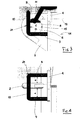
- the polarizing device identified as a whole by 1, therefore consists of a lifting lug 2 and deflector means in the form of a bent plate 3.
- Such a keying device currently equips many types of handling equipment for the construction sector and public works and, in the example shown, the equipment thus equipped is a concrete bucket (identified hereinafter by its body 4) comprising at its upper part an opening 5 through which is introduced the concrete to be transported from its place of manufacture or temporary storage to its place of use.
- a concrete bucket is a particularly heavy and bulky handling equipment, its weight, when it is filled, can reach five tons and its height can exceed two meters.
- Two similar polarizing devices 1 are thus disposed in the upper part of the body 4 of the body and are welded on two opposite sides of said body.
- the lifting lug 2 is a molded metal part, which is pierced with a through hole 6. It is welded substantially perpendicular to the body 4, in a plane which is often substantially vertical, or slightly inclined to the vertical, when the bucket is laid on the ground and is considered in its stable resting position.
- the through hole is intended to receive, for the purpose of their attachment and locking, the ends of the means which, incidentally hooked to the hook of a crane, will lift and move the bucket.
- the bent plate 3 is formed of a first branch 3a, one end 3b of which is welded close to the upper edge of one side of the body 4 of the concrete body, this first branch 3a being inclined by about 55.degree. body 4, and a second branch 3c said free, which is substantially parallel to said body of the body and is turned towards the upper part thereof.
- the plate 3 is able to deform or even break and detach from the body 4 at its weld 3b .
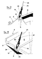
- the deflector 21 associated with the classic lifting lug 2 has the shape of a U and which, in its construction where the wings of this U are not symmetrical with respect to the lifting lug 2, is more particularly intended to equip each of the two opposite sides of the body of a material handling which itself has no symmetry, and for example a so-called concrete dump, that is to say, a bucket which, placed on the ground 27, rests on a cradle 26 and whose body 4, slightly inclined to the horizontal, and the cradle 26 associated with it straighten up when lifting such a bucket.
- the opening 5 through which the concrete is introduced into a dump bed is most often inclined to the horizontal when the bucket rests on the floor, and even strongly inclined since the opening defining said opening can make an angle close to 70 ° with the horizontal schematized here by the ground 27.
- the two wings 8 and 9 extend substantially parallel to the lifting lug 2 and they are of the same length, so that the core 10 is parallel to the body 4 of the bucket.
- the upper line of the left wing 8 is substantially tangential to the plane 12 perpendicular to the lifting lug 2 passing through the upper end point of the through orifice 6 of the ear 2 and the upper line 13 of the right wing. 9 is crossed by the plane 14 perpendicular to the ear 2 passing through the lower end point of said through orifice 6.
- the left wing 8 prefferably be, in its entirety, in the immediate vicinity of the plane 12, that is to say slightly above or slightly below said plane 12, or else that it be tangent to it or crossed by it.
- the right wing 9 is, as a whole, in the immediate vicinity of the plane 14, that is to say slightly above or slightly below said plane 14, or that it be tangent to it or crossed by it.
- each of the two wings 8 and 9 of the U-shaped deflector 21 must be separated from said lug by a distance A at least equal to the thickness of the lifting means 11 for their part which hangs on the ear 2.
- the core 10 of the U-shaped deflector 21 is in turn always external to the ear 2 and comes into contact with said ear or is, at a location, remote from the latter by a distance B which is substantially smaller than the thickness of the means 11, always for their part which hangs on the ear, and in addition said soul 10 is, in all its points, and in particular at its closest point to the ear, always distant from the point 15 the through hole 6 closest to the body 4 by a distance C which is greater than the thickness of the means 11, still for their part that clings to the ear.
- the means 11 now have very limited degrees of freedom: they can not pass between the core 10 of such a U-shaped deflector and the lifting lug 2, they have a transverse travel limited by the core 10 and They have one pivoting limited by the left flank 8 of the polarizer; in other words, even at rest, the means 11 remain in practice in a position extremely close to their good working position, this position being in any case such that said means 11 can not escape, or even s' intermingle.
- the wing 9 farthest from the elbow 16 is disposed on the side of the opening 5 of the dump body, that is to say that it is located in a plane farther from the ground than the plane passing through the wing 8 closest to the elbow 16, the bucket being here considered placed on the ground and in its stable resting position.
- the means 11 When the bucket 4 or any other material handling equipment will have to be lifted, the means 11, first raised by the crane, will rotate as indicated by the arrow 18 around the ear 2, without being at all impeded by the right wing 9 and this even if, to raise the bucket, the crane operator must proceed in spurts, and the bucket 4 will be able to be straightened without difficulty.
- the core 10 of the deflector 21 is not parallel to the body 4 of the bucket by giving different lengths to the wings 8 and 9.
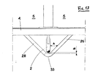
- the keying device according to the invention consists of the classic lifting lug 2 and a deflector 31 V also always made in one piece, from a round bent.
- This second polarizing device will be more particularly intended for the lifting of any handling material substantially symmetrical with respect to the plane passing through the two lifting lugs, for example a so-called right concrete bucket which rests standing on the ground by a base consisting of four feet gathered at their bases, two by two, by means of sleepers, bucket which remains in this same standing position when it is raised.
- any handling material substantially symmetrical with respect to the plane passing through the two lifting lugs, for example a so-called right concrete bucket which rests standing on the ground by a base consisting of four feet gathered at their bases, two by two, by means of sleepers, bucket which remains in this same standing position when it is raised.
- the two wings 28 and 29, respectively left and right on the Figures 8 to 11 , of this deflector 31 are welded to the body 4 of the bucket on either side of the lifting lug 2 and the two wings 28, 29 extend obliquely relative to said ear.
- At least one of the two wings of the V-shaped deflector 31 extends in the immediate vicinity of the plane 32 which is perpendicular to the lifting lug and which passes through the upper end point of the through hole 6 of said ear, or is traversed by this virtual plane 32.
- the pivoting means 11 is limited.
- each of the wings 28, 29 of the V-shaped deflector 31 is, at the right of the through-orifice 6 of the ear, separated from said ear by a distance A less equal to the thickness of the means 11 for lifting the bucket, for their part which hangs on the ear, and the central zone 33 in which is connected the two ends of the wings 28, 29 is external to the ear and comes, at this point, to touch said ear or is, at this point, away from the ear by a distance B significantly less than the thickness of the means 11 for their part that hangs on the hear ; finally, the central connecting zone 33 of the ends of the two wings 28, 29 is further removed from the point 15 of the through-orifice 6 of the ear 2 closest to the body 4 by a distance C greater than the thickness means 11, always for their part that clings to the ear 2.
- At least that of the two wings, for example the right wing 29, which extends in the immediate vicinity of the plane 32 perpendicular to the lifting lug passing through the upper end point of the orifice 6 passing through the ear 2 may thus be located slightly above this plane 32, or is tangent to this plane, when the lifting lug 2 is disposed vertically and the object to be lifted is in the normal lifting position.
- At least the wing 29 above may be located slightly below this plane 32 or is tangent to this plane, when the lifting lug 2 is arranged vertically and the object to be lifted in the normal lifting position. .
- At least the right wing 29 can be traversed by the plane 32, as shown in FIG. Figure 9 .
- the common goal sought in all the aforementioned constructions is that the means 11 have a pivotal freedom limited and thus maintain a position extremely close to their good working position.
- the ends of the two wings of each deflector 21 in U or each deflector 31 V can be located substantially symmetrically relative to the plane 34 that is the vertical plane of symmetry of the lifting lug.
- deflector 31 V-shaped construction that is asymmetrical relative to the lifting lug 2.
- the wing 28 of such a deflector 31 is born, according to the common characteristic of all the deflectors described above, near the plane 32, or is traversed by this virtual plane 32, while the second wing 29 originates near the plane 35 perpendicular to the lifting lug 2 passing through the lower extreme point of the through this virtual plane 35.
- the deflector 31 will cross obliquely the lifting lug, always at the level of the connection zone 33 of the two wings 28, 29, the latter up be of equal lengths or different lengths if the shape and / or weight of the object to be lifted or the shape of the ends 11 of the lifting means imposes.
- the deflectors 21 U and 31 V have the advantage of being almost indeformable. In addition, since these deflectors are devoid of any flat part, the risks of jamming of the ends 11 of the lifting means are completely eliminated, and the problems due to the concrete retainers are also removed. Another advantage of the bent rounds is that they are not aggressive with respect to the ends 11 of the lifting means.
- connecting link 11 also called connecting ring, or coupling link, or coupling assembly link, that is to say a link formed of two identical pieces in J, arranged head to tail and joined by two pins.
- connection link 11 shown in Figures 3 and 5 at 9 another link 19 will be engaged, called a head mesh, that is to say a closed ring, in which a safety hook 20 will be engaged, said hook BK, which will be associated with the lifting means properly speak, and for example a sling 22 terminated by a sleeve 23 formed after crushing (see Figure 7 ), or a chain 24 endowed at its end with a link 25 or a shackle serving as intermediate means of connection with the safety hook 20 (see Figure 8 ), or even more simply straps whose ends will each have a connecting link.
Applications Claiming Priority (1)
| Application Number | Priority Date | Filing Date | Title |
|---|---|---|---|
| FR1102693A FR2979623B1 (fr) | 2011-09-06 | 2011-09-06 | Dispositif detrompeur pour l'accrochage de moyens permettant le levage d'objets particulierement lourds et encombrants, en vue de leur deplacement, et objets equipes d'un tel dispositif detrompeur |
Publications (2)
| Publication Number | Publication Date |
|---|---|
| EP2573037A1 true EP2573037A1 (de) | 2013-03-27 |
| EP2573037B1 EP2573037B1 (de) | 2013-12-11 |
Family
ID=46799175
Family Applications (1)
| Application Number | Title | Priority Date | Filing Date |
|---|---|---|---|
| EP12290291.9A Active EP2573037B1 (de) | 2011-09-06 | 2012-09-05 | Fixiervorrichtung für die Aufhängung von Mitteln zum Heben von besonders schweren und sperrigen Gegenständen, die transportiert werden sollen, und mit einer solchen Fixiervorrichtung ausgestattete Gegenstände |
Country Status (3)
| Country | Link |
|---|---|
| EP (1) | EP2573037B1 (de) |
| ES (1) | ES2450921T3 (de) |
| FR (1) | FR2979623B1 (de) |
Families Citing this family (1)
| Publication number | Priority date | Publication date | Assignee | Title |
|---|---|---|---|---|
| FR3035135B1 (fr) | 2015-04-17 | 2018-04-20 | Secatol | Benne a beton couchee dont le pietement permet une reprise de ladite benne par les fourches d'un chariot elevateur |
Citations (3)
| Publication number | Priority date | Publication date | Assignee | Title |
|---|---|---|---|---|
| US20030180118A1 (en) * | 2002-03-19 | 2003-09-25 | Alba Tony J. | Fixed eyebolt assembly and inventory thereof |
| AT412269B (de) * | 2003-08-13 | 2004-12-27 | Pewag Austria Gmbh | Anschlussvorrichtung sowie fixierelement |
| DE102006052986A1 (de) * | 2005-12-10 | 2007-06-14 | J. D. Theile Gmbh & Co. Kg | Anschlagpunkt |
-
2011
- 2011-09-06 FR FR1102693A patent/FR2979623B1/fr not_active Expired - Fee Related
-
2012
- 2012-09-05 ES ES12290291.9T patent/ES2450921T3/es active Active
- 2012-09-05 EP EP12290291.9A patent/EP2573037B1/de active Active
Patent Citations (3)
| Publication number | Priority date | Publication date | Assignee | Title |
|---|---|---|---|---|
| US20030180118A1 (en) * | 2002-03-19 | 2003-09-25 | Alba Tony J. | Fixed eyebolt assembly and inventory thereof |
| AT412269B (de) * | 2003-08-13 | 2004-12-27 | Pewag Austria Gmbh | Anschlussvorrichtung sowie fixierelement |
| DE102006052986A1 (de) * | 2005-12-10 | 2007-06-14 | J. D. Theile Gmbh & Co. Kg | Anschlagpunkt |
Also Published As
| Publication number | Publication date |
|---|---|
| FR2979623A1 (fr) | 2013-03-08 |
| EP2573037B1 (de) | 2013-12-11 |
| FR2979623B1 (fr) | 2013-08-30 |
| ES2450921T3 (es) | 2014-03-25 |
Similar Documents
| Publication | Publication Date | Title |
|---|---|---|
| EP2636606A1 (de) | Vorrichtung zur Aufnahme, Förderung und Entleerung eines flexiblen Behälters | |
| EP3009570B1 (de) | Werkzeughalter für baustellen- oder baumaschine | |
| EP2573037B1 (de) | Fixiervorrichtung für die Aufhängung von Mitteln zum Heben von besonders schweren und sperrigen Gegenständen, die transportiert werden sollen, und mit einer solchen Fixiervorrichtung ausgestattete Gegenstände | |
| FR2697302A1 (fr) | Dispositif d'attache rapide pour équipement d'engin de génie civil et de manutention. | |
| FR2889223A1 (fr) | Structure de travail en encorbeillement | |
| EP1091046B1 (de) | Verschlussvorrichtung für einen Kontroll- oder Inspektionsschacht | |
| FR2899253A1 (fr) | Dispositif de securite pour l'acces a une chambre technique situee sous une chaussee ou analogue | |
| EP2686489A2 (de) | Anordnung mit einem tragrahmen und einem umdrehbaren fallverhinderungsgitter | |
| EP2927160B1 (de) | Baustellen-kippwanne mit reduzierter breite, die durch alle türen passt und ein versenkbares anschlaggeschirr zum rangieren umfasst | |
| CA2146640C (fr) | Anneau de levage | |
| FR2824783A1 (fr) | Chariot de manutention | |
| FR3035135A1 (fr) | Benne a beton couchee dont le pietement permet une reprise de ladite benne par les fourches d'un chariot elevateur | |
| FR2544681A1 (fr) | Brouette a benne basculante | |
| EP2907772B1 (de) | Sicherheits- und Beladevorrichtung für Abfallsammelstelle | |
| FR2698650A1 (fr) | Passerelle pour le franchissement d'obstacle. | |
| FR3035092A1 (fr) | Equipement de securite pour quai de dechetterie | |
| WO2014177465A1 (fr) | Cadre pour tour d'etaiement avec garde-corps integre | |
| EP0591028B1 (de) | Unteres Bordwandscharnier für Fahrzeugladepritschen | |
| FR3018271A1 (fr) | Benne a deux elements articules et a ouverture par le bas. | |
| EP1278915B1 (de) | Schnellkupplungsvorrichtung zur befestigung eines werkzeugs am ende eines laderauslegers oder dgl | |
| FR2986218A1 (fr) | Systeme de prehension et de levage d'un conteneur de collecte des dechets et de commande d'ouverture/fermeture des trappes de vidage dudit conteneur | |
| FR2910916A1 (fr) | Mur a coffrage integre comportant un moyen provisoire de mise en place d'un moyen de raccordement du mur a un dispositif de levage | |
| FR2781383A1 (fr) | Perfectionnement pour dispositif de support de devidoir mobile de tuyau | |
| FR3024740A1 (fr) | Dispositif de montage rapide d'un outil sur le bras d'une machine | |
| BE1007563A6 (fr) | Dispositif pour poser des elements de voirie. |
Legal Events
| Date | Code | Title | Description |
|---|---|---|---|
| PUAI | Public reference made under article 153(3) epc to a published international application that has entered the european phase |
Free format text: ORIGINAL CODE: 0009012 |
|
| 17P | Request for examination filed |
Effective date: 20120925 |
|
| AK | Designated contracting states |
Kind code of ref document: A1 Designated state(s): AL AT BE BG CH CY CZ DE DK EE ES FI FR GB GR HR HU IE IS IT LI LT LU LV MC MK MT NL NO PL PT RO RS SE SI SK SM TR |
|
| AX | Request for extension of the european patent |
Extension state: BA ME |
|
| RIC1 | Information provided on ipc code assigned before grant |
Ipc: B66C 1/66 20060101AFI20130425BHEP |
|
| GRAP | Despatch of communication of intention to grant a patent |
Free format text: ORIGINAL CODE: EPIDOSNIGR1 |
|
| INTG | Intention to grant announced |
Effective date: 20130627 |
|
| GRAS | Grant fee paid |
Free format text: ORIGINAL CODE: EPIDOSNIGR3 |
|
| GRAA | (expected) grant |
Free format text: ORIGINAL CODE: 0009210 |
|
| AK | Designated contracting states |
Kind code of ref document: B1 Designated state(s): AL AT BE BG CH CY CZ DE DK EE ES FI FR GB GR HR HU IE IS IT LI LT LU LV MC MK MT NL NO PL PT RO RS SE SI SK SM TR |
|
| REG | Reference to a national code |
Ref country code: GB Ref legal event code: FG4D Free format text: NOT ENGLISH |
|
| REG | Reference to a national code |
Ref country code: CH Ref legal event code: EP |
|
| REG | Reference to a national code |
Ref country code: AT Ref legal event code: REF Ref document number: 644465 Country of ref document: AT Kind code of ref document: T Effective date: 20140115 |
|
| REG | Reference to a national code |
Ref country code: IE Ref legal event code: FG4D Free format text: LANGUAGE OF EP DOCUMENT: FRENCH |
|
| REG | Reference to a national code |
Ref country code: DE Ref legal event code: R096 Ref document number: 602012000652 Country of ref document: DE Effective date: 20140206 |
|
| REG | Reference to a national code |
Ref country code: CH Ref legal event code: NV Representative=s name: INTERPAT LAW AG, CH |
|
| REG | Reference to a national code |
Ref country code: ES Ref legal event code: FG2A Ref document number: 2450921 Country of ref document: ES Kind code of ref document: T3 Effective date: 20140325 |
|
| REG | Reference to a national code |
Ref country code: NL Ref legal event code: VDEP Effective date: 20131211 |
|
| REG | Reference to a national code |
Ref country code: AT Ref legal event code: MK05 Ref document number: 644465 Country of ref document: AT Kind code of ref document: T Effective date: 20131211 |
|
| PG25 | Lapsed in a contracting state [announced via postgrant information from national office to epo] |
Ref country code: NL Free format text: LAPSE BECAUSE OF FAILURE TO SUBMIT A TRANSLATION OF THE DESCRIPTION OR TO PAY THE FEE WITHIN THE PRESCRIBED TIME-LIMIT Effective date: 20131211 Ref country code: SE Free format text: LAPSE BECAUSE OF FAILURE TO SUBMIT A TRANSLATION OF THE DESCRIPTION OR TO PAY THE FEE WITHIN THE PRESCRIBED TIME-LIMIT Effective date: 20131211 Ref country code: NO Free format text: LAPSE BECAUSE OF FAILURE TO SUBMIT A TRANSLATION OF THE DESCRIPTION OR TO PAY THE FEE WITHIN THE PRESCRIBED TIME-LIMIT Effective date: 20140311 Ref country code: FI Free format text: LAPSE BECAUSE OF FAILURE TO SUBMIT A TRANSLATION OF THE DESCRIPTION OR TO PAY THE FEE WITHIN THE PRESCRIBED TIME-LIMIT Effective date: 20131211 Ref country code: HR Free format text: LAPSE BECAUSE OF FAILURE TO SUBMIT A TRANSLATION OF THE DESCRIPTION OR TO PAY THE FEE WITHIN THE PRESCRIBED TIME-LIMIT Effective date: 20131211 Ref country code: LT Free format text: LAPSE BECAUSE OF FAILURE TO SUBMIT A TRANSLATION OF THE DESCRIPTION OR TO PAY THE FEE WITHIN THE PRESCRIBED TIME-LIMIT Effective date: 20131211 |
|
| REG | Reference to a national code |
Ref country code: LT Ref legal event code: MG4D |
|
| PG25 | Lapsed in a contracting state [announced via postgrant information from national office to epo] |
Ref country code: LV Free format text: LAPSE BECAUSE OF FAILURE TO SUBMIT A TRANSLATION OF THE DESCRIPTION OR TO PAY THE FEE WITHIN THE PRESCRIBED TIME-LIMIT Effective date: 20131211 Ref country code: RS Free format text: LAPSE BECAUSE OF FAILURE TO SUBMIT A TRANSLATION OF THE DESCRIPTION OR TO PAY THE FEE WITHIN THE PRESCRIBED TIME-LIMIT Effective date: 20131211 Ref country code: AT Free format text: LAPSE BECAUSE OF FAILURE TO SUBMIT A TRANSLATION OF THE DESCRIPTION OR TO PAY THE FEE WITHIN THE PRESCRIBED TIME-LIMIT Effective date: 20131211 Ref country code: CY Free format text: LAPSE BECAUSE OF FAILURE TO SUBMIT A TRANSLATION OF THE DESCRIPTION OR TO PAY THE FEE WITHIN THE PRESCRIBED TIME-LIMIT Effective date: 20131211 |
|
| PG25 | Lapsed in a contracting state [announced via postgrant information from national office to epo] |
Ref country code: IS Free format text: LAPSE BECAUSE OF FAILURE TO SUBMIT A TRANSLATION OF THE DESCRIPTION OR TO PAY THE FEE WITHIN THE PRESCRIBED TIME-LIMIT Effective date: 20140411 Ref country code: EE Free format text: LAPSE BECAUSE OF FAILURE TO SUBMIT A TRANSLATION OF THE DESCRIPTION OR TO PAY THE FEE WITHIN THE PRESCRIBED TIME-LIMIT Effective date: 20131211 |
|
| PG25 | Lapsed in a contracting state [announced via postgrant information from national office to epo] |
Ref country code: PT Free format text: LAPSE BECAUSE OF FAILURE TO SUBMIT A TRANSLATION OF THE DESCRIPTION OR TO PAY THE FEE WITHIN THE PRESCRIBED TIME-LIMIT Effective date: 20140411 Ref country code: RO Free format text: LAPSE BECAUSE OF FAILURE TO SUBMIT A TRANSLATION OF THE DESCRIPTION OR TO PAY THE FEE WITHIN THE PRESCRIBED TIME-LIMIT Effective date: 20131211 Ref country code: CZ Free format text: LAPSE BECAUSE OF FAILURE TO SUBMIT A TRANSLATION OF THE DESCRIPTION OR TO PAY THE FEE WITHIN THE PRESCRIBED TIME-LIMIT Effective date: 20131211 Ref country code: SK Free format text: LAPSE BECAUSE OF FAILURE TO SUBMIT A TRANSLATION OF THE DESCRIPTION OR TO PAY THE FEE WITHIN THE PRESCRIBED TIME-LIMIT Effective date: 20131211 Ref country code: PL Free format text: LAPSE BECAUSE OF FAILURE TO SUBMIT A TRANSLATION OF THE DESCRIPTION OR TO PAY THE FEE WITHIN THE PRESCRIBED TIME-LIMIT Effective date: 20131211 |
|
| REG | Reference to a national code |
Ref country code: DE Ref legal event code: R097 Ref document number: 602012000652 Country of ref document: DE |
|
| PLBE | No opposition filed within time limit |
Free format text: ORIGINAL CODE: 0009261 |
|
| STAA | Information on the status of an ep patent application or granted ep patent |
Free format text: STATUS: NO OPPOSITION FILED WITHIN TIME LIMIT |
|
| PG25 | Lapsed in a contracting state [announced via postgrant information from national office to epo] |
Ref country code: DK Free format text: LAPSE BECAUSE OF FAILURE TO SUBMIT A TRANSLATION OF THE DESCRIPTION OR TO PAY THE FEE WITHIN THE PRESCRIBED TIME-LIMIT Effective date: 20131211 |
|
| 26N | No opposition filed |
Effective date: 20140912 |
|
| REG | Reference to a national code |
Ref country code: DE Ref legal event code: R097 Ref document number: 602012000652 Country of ref document: DE Effective date: 20140912 |
|
| PG25 | Lapsed in a contracting state [announced via postgrant information from national office to epo] |
Ref country code: SI Free format text: LAPSE BECAUSE OF FAILURE TO SUBMIT A TRANSLATION OF THE DESCRIPTION OR TO PAY THE FEE WITHIN THE PRESCRIBED TIME-LIMIT Effective date: 20131211 |
|
| REG | Reference to a national code |
Ref country code: IE Ref legal event code: MM4A |
|
| PG25 | Lapsed in a contracting state [announced via postgrant information from national office to epo] |
Ref country code: IE Free format text: LAPSE BECAUSE OF NON-PAYMENT OF DUE FEES Effective date: 20140905 |
|
| REG | Reference to a national code |
Ref country code: FR Ref legal event code: PLFP Year of fee payment: 4 |
|
| PG25 | Lapsed in a contracting state [announced via postgrant information from national office to epo] |
Ref country code: SM Free format text: LAPSE BECAUSE OF FAILURE TO SUBMIT A TRANSLATION OF THE DESCRIPTION OR TO PAY THE FEE WITHIN THE PRESCRIBED TIME-LIMIT Effective date: 20131211 |
|
| PG25 | Lapsed in a contracting state [announced via postgrant information from national office to epo] |
Ref country code: MT Free format text: LAPSE BECAUSE OF FAILURE TO SUBMIT A TRANSLATION OF THE DESCRIPTION OR TO PAY THE FEE WITHIN THE PRESCRIBED TIME-LIMIT Effective date: 20131211 Ref country code: GR Free format text: LAPSE BECAUSE OF FAILURE TO SUBMIT A TRANSLATION OF THE DESCRIPTION OR TO PAY THE FEE WITHIN THE PRESCRIBED TIME-LIMIT Effective date: 20140312 Ref country code: BG Free format text: LAPSE BECAUSE OF FAILURE TO SUBMIT A TRANSLATION OF THE DESCRIPTION OR TO PAY THE FEE WITHIN THE PRESCRIBED TIME-LIMIT Effective date: 20131211 |
|
| PG25 | Lapsed in a contracting state [announced via postgrant information from national office to epo] |
Ref country code: TR Free format text: LAPSE BECAUSE OF FAILURE TO SUBMIT A TRANSLATION OF THE DESCRIPTION OR TO PAY THE FEE WITHIN THE PRESCRIBED TIME-LIMIT Effective date: 20131211 Ref country code: HU Free format text: LAPSE BECAUSE OF FAILURE TO SUBMIT A TRANSLATION OF THE DESCRIPTION OR TO PAY THE FEE WITHIN THE PRESCRIBED TIME-LIMIT; INVALID AB INITIO Effective date: 20120905 |
|
| REG | Reference to a national code |
Ref country code: FR Ref legal event code: PLFP Year of fee payment: 5 |
|
| REG | Reference to a national code |
Ref country code: FR Ref legal event code: PLFP Year of fee payment: 6 |
|
| PG25 | Lapsed in a contracting state [announced via postgrant information from national office to epo] |
Ref country code: MK Free format text: LAPSE BECAUSE OF FAILURE TO SUBMIT A TRANSLATION OF THE DESCRIPTION OR TO PAY THE FEE WITHIN THE PRESCRIBED TIME-LIMIT Effective date: 20131211 |
|
| REG | Reference to a national code |
Ref country code: FR Ref legal event code: PLFP Year of fee payment: 7 |
|
| PG25 | Lapsed in a contracting state [announced via postgrant information from national office to epo] |
Ref country code: AL Free format text: LAPSE BECAUSE OF FAILURE TO SUBMIT A TRANSLATION OF THE DESCRIPTION OR TO PAY THE FEE WITHIN THE PRESCRIBED TIME-LIMIT Effective date: 20131211 |
|
| P01 | Opt-out of the competence of the unified patent court (upc) registered |
Effective date: 20230606 |
|
| PGFP | Annual fee paid to national office [announced via postgrant information from national office to epo] |
Ref country code: MC Payment date: 20230919 Year of fee payment: 12 Ref country code: LU Payment date: 20230921 Year of fee payment: 12 Ref country code: IT Payment date: 20230920 Year of fee payment: 12 |
|
| PGFP | Annual fee paid to national office [announced via postgrant information from national office to epo] |
Ref country code: FR Payment date: 20230906 Year of fee payment: 12 Ref country code: DE Payment date: 20230928 Year of fee payment: 12 Ref country code: BE Payment date: 20230920 Year of fee payment: 12 |
|
| PGFP | Annual fee paid to national office [announced via postgrant information from national office to epo] |
Ref country code: GB Payment date: 20231006 Year of fee payment: 12 |
|
| PGFP | Annual fee paid to national office [announced via postgrant information from national office to epo] |
Ref country code: ES Payment date: 20231003 Year of fee payment: 12 |
|
| PGFP | Annual fee paid to national office [announced via postgrant information from national office to epo] |
Ref country code: CH Payment date: 20231002 Year of fee payment: 12 |