EP2571763B1 - Hybrides antriebs- und energiesystem für fluggeräte - Google Patents
Hybrides antriebs- und energiesystem für fluggeräte Download PDFInfo
- Publication number
- EP2571763B1 EP2571763B1 EP11720491.7A EP11720491A EP2571763B1 EP 2571763 B1 EP2571763 B1 EP 2571763B1 EP 11720491 A EP11720491 A EP 11720491A EP 2571763 B1 EP2571763 B1 EP 2571763B1
- Authority
- EP
- European Patent Office
- Prior art keywords
- helicopter
- tail rotor
- electric motor
- rotor
- hybrid drive
- Prior art date
- Legal status (The legal status is an assumption and is not a legal conclusion. Google has not performed a legal analysis and makes no representation as to the accuracy of the status listed.)
- Active
Links
- 238000002485 combustion reaction Methods 0.000 claims description 36
- 239000000446 fuel Substances 0.000 claims description 8
- 238000000034 method Methods 0.000 claims description 7
- 238000010248 power generation Methods 0.000 description 31
- 230000005540 biological transmission Effects 0.000 description 10
- 230000008878 coupling Effects 0.000 description 4
- 238000010168 coupling process Methods 0.000 description 4
- 238000005859 coupling reaction Methods 0.000 description 4
- 238000011161 development Methods 0.000 description 2
- 230000018109 developmental process Effects 0.000 description 2
- 208000032369 Primary transmission Diseases 0.000 description 1
- 208000032370 Secondary transmission Diseases 0.000 description 1
- 238000010276 construction Methods 0.000 description 1
- 238000004146 energy storage Methods 0.000 description 1
- 230000005284 excitation Effects 0.000 description 1
- 230000005484 gravity Effects 0.000 description 1
- 210000000056 organ Anatomy 0.000 description 1
- XLYOFNOQVPJJNP-UHFFFAOYSA-N water Substances O XLYOFNOQVPJJNP-UHFFFAOYSA-N 0.000 description 1
Images


Classifications
-
- F—MECHANICAL ENGINEERING; LIGHTING; HEATING; WEAPONS; BLASTING
- F02—COMBUSTION ENGINES; HOT-GAS OR COMBUSTION-PRODUCT ENGINE PLANTS
- F02B—INTERNAL-COMBUSTION PISTON ENGINES; COMBUSTION ENGINES IN GENERAL
- F02B63/00—Adaptations of engines for driving pumps, hand-held tools or electric generators; Portable combinations of engines with engine-driven devices
- F02B63/04—Adaptations of engines for driving pumps, hand-held tools or electric generators; Portable combinations of engines with engine-driven devices for electric generators
-
- B—PERFORMING OPERATIONS; TRANSPORTING
- B64—AIRCRAFT; AVIATION; COSMONAUTICS
- B64C—AEROPLANES; HELICOPTERS
- B64C27/00—Rotorcraft; Rotors peculiar thereto
-
- B—PERFORMING OPERATIONS; TRANSPORTING
- B64—AIRCRAFT; AVIATION; COSMONAUTICS
- B64C—AEROPLANES; HELICOPTERS
- B64C27/00—Rotorcraft; Rotors peculiar thereto
- B64C27/04—Helicopters
- B64C27/12—Rotor drives
- B64C27/14—Direct drive between power plant and rotor hub
-
- B—PERFORMING OPERATIONS; TRANSPORTING
- B64—AIRCRAFT; AVIATION; COSMONAUTICS
- B64C—AEROPLANES; HELICOPTERS
- B64C27/00—Rotorcraft; Rotors peculiar thereto
- B64C27/82—Rotorcraft; Rotors peculiar thereto characterised by the provision of an auxiliary rotor or fluid-jet device for counter-balancing lifting rotor torque or changing direction of rotorcraft
-
- B64D27/026—
-
- B—PERFORMING OPERATIONS; TRANSPORTING
- B64—AIRCRAFT; AVIATION; COSMONAUTICS
- B64D—EQUIPMENT FOR FITTING IN OR TO AIRCRAFT; FLIGHT SUITS; PARACHUTES; ARRANGEMENTS OR MOUNTING OF POWER PLANTS OR PROPULSION TRANSMISSIONS IN AIRCRAFT
- B64D27/00—Arrangement or mounting of power plant in aircraft; Aircraft characterised thereby
- B64D27/02—Aircraft characterised by the type or position of power plant
- B64D27/24—Aircraft characterised by the type or position of power plant using steam, electricity, or spring force
-
- B—PERFORMING OPERATIONS; TRANSPORTING
- B64—AIRCRAFT; AVIATION; COSMONAUTICS
- B64C—AEROPLANES; HELICOPTERS
- B64C27/00—Rotorcraft; Rotors peculiar thereto
- B64C27/82—Rotorcraft; Rotors peculiar thereto characterised by the provision of an auxiliary rotor or fluid-jet device for counter-balancing lifting rotor torque or changing direction of rotorcraft
- B64C2027/8209—Electrically driven tail rotors
-
- Y—GENERAL TAGGING OF NEW TECHNOLOGICAL DEVELOPMENTS; GENERAL TAGGING OF CROSS-SECTIONAL TECHNOLOGIES SPANNING OVER SEVERAL SECTIONS OF THE IPC; TECHNICAL SUBJECTS COVERED BY FORMER USPC CROSS-REFERENCE ART COLLECTIONS [XRACs] AND DIGESTS
- Y02—TECHNOLOGIES OR APPLICATIONS FOR MITIGATION OR ADAPTATION AGAINST CLIMATE CHANGE
- Y02T—CLIMATE CHANGE MITIGATION TECHNOLOGIES RELATED TO TRANSPORTATION
- Y02T50/00—Aeronautics or air transport
- Y02T50/60—Efficient propulsion technologies, e.g. for aircraft
-
- Y—GENERAL TAGGING OF NEW TECHNOLOGICAL DEVELOPMENTS; GENERAL TAGGING OF CROSS-SECTIONAL TECHNOLOGIES SPANNING OVER SEVERAL SECTIONS OF THE IPC; TECHNICAL SUBJECTS COVERED BY FORMER USPC CROSS-REFERENCE ART COLLECTIONS [XRACs] AND DIGESTS
- Y10—TECHNICAL SUBJECTS COVERED BY FORMER USPC
- Y10S—TECHNICAL SUBJECTS COVERED BY FORMER USPC CROSS-REFERENCE ART COLLECTIONS [XRACs] AND DIGESTS
- Y10S903/00—Hybrid electric vehicles, HEVS
- Y10S903/902—Prime movers comprising electrical and internal combustion motors
- Y10S903/903—Prime movers comprising electrical and internal combustion motors having energy storing means, e.g. battery, capacitor
Definitions
- the invention relates to a hybrid propulsion system for aircraft, in particular helicopters, and helicopters with such a hybrid propulsion system.
- helicopters are usually powered by one or more gas turbines, wherein the high speed of the gas turbine must be reduced by a transmission from which the rotors of the helicopter are mechanically driven, such as a main rotor and a tail rotor.
- a transmission from which the rotors of the helicopter are mechanically driven, such as a main rotor and a tail rotor.
- a hybrid propulsion system for aircraft which has a gas turbine for generating a first drive energy and an electric motor for generating a second drive energy.
- the gas turbine and the electric motor are designed such that a drive unit, for example a propeller, of the aircraft can be provided with the first and / or the second drive energy.
- a coupling between the gas turbine and the electric motor is required, or a first coupling between the gas turbine and the propeller shaft and a second coupling between the electric motor and the propeller shaft.
- a fuel cell system and a battery may be provided.
- From the DE 10 2006 056 356 A1 is a drive with several energy converters known for an aircraft, each of which energy converter as a gas turbine, piston engine or electric motor can be formed. Again, a coupling between a first and a second energy converter is required, or between the first and the second energy converter and a propeller. In this context, it is also mentioned that only one electric motor is used for cruising or in the vicinity of an airfield, whereas an internal combustion engine is additionally required for take-off and landing.
- an aircraft propeller drive having a propeller, an engine, and a driveline between the propeller and the engine is proposed in which the driveline includes a torsional vibration damper.
- an electric machine may be provided, which can charge a battery connected as a generator, and connected as an electric motor, and powered by the battery, can provide drive in addition to the diesel engine.
- the DE 10 2008 014 404 A1 describes an unmanned helicopter with a hybrid drive, in which a fuel motor drives a generator for power generation, and the current feeds a primary drive for rotor blades working electric motor and / or backup batteries, the electric motor can also be supplied with power from the backup batteries.
- the US 2009/0145998 A1 describes a hybrid drive helicopter having a gas turbine and an electric power generator drivable therefrom by a primary transmission shaft.
- An electric motor is used to drive a main rotor and can be optionally powered by the generator or a battery pack that stores electrical energy.
- One or more other rotors are driven by a secondary transmission shaft.
- the US 4,605,185 describes a fixed wing aircraft with a hybrid drive, the an internal combustion engine and a generator that generates power for a first electric motor that drives a first propeller, and for a second electric motor that drives a second propeller.
- an emergency battery is provided, which then provides power for the two electric motors.
- the US 2006/0048988 A1 describes a hybrid drive for vehicles, such as land, water or air vehicles, having an internal combustion engine and one or more electrical machines, both of which can operate as an electric motor or as a generator.
- An accumulator can be charged by both generators.
- one electric motor may drive an automatic transmission of one vehicle, and the other electric motor may drive an oil pump of the vehicle to provide hydraulic pressure to actuators.
- the US 4,554,989 describes a helicopter with a hybrid drive having a turbine engine driving a generator that supplies power to a first electric motor that drives a main rotor and to a second electric motor that drives a tail rotor.
- the FR 2 931 456 A1 (or the parallel, not prepublished US 2011/0073717 A1 ) describes a fixed wing aircraft whose propulsion is done by internal combustion engines. Electrical energy is generated by solar cells and supplies the electrical system of the aircraft. If excess electrical energy is present, then the excess can be used in each case to supply an electrical machine that supports the respective internal combustion engine.
- the WO 2009/025 231 A1 (or the parallel, not prepublished US 2010/0127114171 A1 ) describes a helicopter with a main rotor and one or more tail rotors, which are about the mast axis of the main rotor over respective linkage can be pivoted to produce thrust components transverse to the longitudinal axis of the helicopter (as usual) and / or in the forward direction of the helicopter.
- the DE 1 581 060 B1 describes a helicopter with a pivotable about a vertical axis tail rotor and a rudder, the tail rotor, with or without gear, is slightly displaceable in the direction of its axis of rotation against the action of a thrust measuring device, the thrust of the tail rotor during its pivoting by means of a whose pitch control device controls the regulator to a constant value close to zero.
- the object underlying the invention is to provide an alternative hybrid propulsion and power system for aircraft.
- a hybrid propulsion system for aircraft in particular helicopters, proposed, with at least one power generation module with an internal combustion engine and a generator driven by this for generating electrical energy, and at least one electric motor for (direct or indirect) driving a drive means of the aircraft.
- Drive means are main and tail rotor of a helicopter.
- the electric motor may provide additional power for a conventional propulsion of a helicopter.
- a second electric motor for driving a second drive means of the aircraft wherein the second drive means is a tail rotor of a helicopter.
- at least one further power generation module is provided. This may be a combination of a second internal combustion engine and a second generator; but also about a fuel cell unit.
- a storage unit for electrical energy is provided, for example a battery unit. This storage unit may be configured to allow helicopter take-off and climb-up to be solely or largely performed by energizing the storage unit including a first electric motor for driving a first drive means and a second electric motor for driving a second drive means of the helicopter drives.
- a further, additional storage unit for electrical energy such as a battery unit, may be provided.
- the further energy generation module is designed as a fuel cell unit. This can be used in place of a combustion engine and generator power generation module, if this fails, but also in addition to one or more power generation modules.
- the invention relates to a helicopter with a hybrid drive system, as described above.
- such a helicopter is provided with a main rotor and a tail rotor, which is designed as a jacketed tail rotor, which is rotatable about a vertical axis of the helicopter.
- the tail rotor and the tail rotor drive can be pivoted about the vertical axis of the helicopter to contribute to propulsion in forward flight.
- the jacketed tail rotor can be rotatably mounted above and below and equipped with at least one adjustment actuator.
- the tail rotor is rotated only so far that still a sufficiently lateral thrust component remains.
- the jacketed tail rotor can be rotated so far around the vertical axis that it only generates propulsion in the direction of flight, a rudder can be provided, which takes over the torque compensation in forward flight.
- the invention relates to a method for controlling a hybrid propulsion system or for controlling a helicopter with such a hybrid propulsion system according to the invention, in which at an increased power requirement of the one power generation module additionally the further power generation module and / or the storage unit for electrical energy is switched on.
- the at least one electric motor in the takeoff and landing phases of the aircraft, is supplied only by the electric energy storage unit. This results in lower noise emissions compared to a conventional aircraft or helicopter drive.
- the engine may be idling or significantly below its rated power during operation.
- the tail rotor thereof for controlling a helicopter, is rotated so far about the vertical axis that a lateral thrust component of the (jacketed) tail rotor compensates for the yaw moment caused by the main rotor.
- the tail rotor provides a lateral thrust component for compensating the yaw moment caused by the main rotor and, moreover, the thrust component in the forward direction (flight direction).
- the procedure may be such that the tail rotor is rotated so far about the vertical axis that the tail rotor thrust is directed rearward in the direction of the longitudinal axis of the helicopter, and the yaw moment caused by the main rotor is adjusted accordingly of the rudder is compensated. This provides optimal support for propulsion through the tail rotor.
- the noise emission from the cabin area (main rotor) of the helicopter further displaced rearward toward the tail rotor, whereby the noise and noise in the cabin of the helicopter is reduced.
- Fig. 1 schematically shows the hybrid propulsion system for aircraft, especially helicopters.
- a conventional helicopter drive is shown, with an internal combustion engine 10 which drives an input E1 of a transmission 14 via a shaft 12, in which case the transmission via an output A1, a shaft 16 and with this one Main rotor 18 drives, and via a further output A2 via a shaft 20 a tail rotor 22 of the helicopter.
- Generator 24 supplies via a line 26 power to an electric motor 30 which drives via a shaft 36 an input E2 of the transmission 14 and thus provides additional power available.
- the generator 24 can charge a battery 32 via a line 28, and the battery 32 via a line 34, the electric motor 30 to provide power, such as in addition to the power supply by the generator 24, or alternatively.
- a hybrid propulsion system for helicopters having an internal combustion engine 42 which drives a generator 46 via a shaft 44.
- Generator 46 supplied via a line 56, a first electric motor 60 with power, which drives a main rotor 64 of the helicopter via a shaft 62.
- the generator supplied via a line 48, a second electric motor 50 with power, which drives a tail rotor 54 of the helicopter via a shaft 52.
- the generator 46 may charge a battery (a battery pack) 68 via a line 66. This can be done, for example, in the cruising flight of the helicopter, when the power requirement for the electric motor 1 of the main rotor 64 is not as large as at start.
- the battery 60 may supply power to the first electric motor 60 via a line 74, a switch S1, and a line 76, in addition to, or alternatively to, power to the generator 46. Accordingly, the battery 68 can supply power to the second electric motor 2 for the tail rotor 64 via a line 70 and a switch S2 and a further line 72.
- a hybrid propulsion system for a helicopter is shown in which a first power generation module with internal combustion engine 82 and generator 86 and a second power generation module with a second internal combustion engine 116 and a second generator 120 are provided.
- These two power generation modules can be operated together or alternatively, if they apply a corresponding, required for the operation of the helicopter performance. However, it may also, for example, in certain operating conditions of the helicopter more power from the first power generation module 82, 86 are applied, and in other operating conditions, more power from the second power generation module 116, 120.
- the first generator 86 supplies via a line 88 power to a generally designated by the reference numeral 90 battery pack having individual battery sub-groups 92, 94, 96, 98, 100, in any combination with one of the inputs (lines 88, 122) and Outputs (lines 104, 126) of the battery unit 90 can be connected.
- the first generator 86 can supply via a line 88 and a switch S1 and a line 104 a first electric motor 106, which drives the main rotor 110 of the helicopter via a shaft 108.
- the generator 86 can also supply via the line 102 and a switch S3 and lines 112, 126 a second electric motor 128 which drives the tail rotor 132 of the helicopter via a shaft 130.
- the second generator 120 which can supply the second electric motor 128 via the line 122 and a line 124 and a switch S2 and the line 126, or via the line 124 and a switch S4 and a line 114 and the line 104, the first electric motor 106.
- the hybrid drive system shown in FIG. 2 has high redundancy due to the first power generation module 82, 86, the second power generation module 116, 120, and the battery unit 90, which is an energy cache and thus another power generation module for the first electric motor 106 and / or the second electric motor 128.
- Each power generation module in Fig. 3 can be arranged in a suitable location in the helicopter, regardless of the first electric motor 106 for Drive the main rotor 110 and the second electric motor 128 for the tail rotor 132.
- the two power generation modules can be arranged below the cabin floor of a helicopter, as well as the battery unit 90. This ensures that not as in conventional helicopter drives relatively heavy components relatively far must be located above in the helicopter, but the center of gravity of the helicopter can be moved down.
- the electric motors used in the invention are preferably designed as a low-inertia direct drive high power density, as in DE 10 2007 013 732 A1 described, so as electrical machines with permanent excitation, which are suitable by high specific torque and power density and a low moment of inertia, especially for direct drive of the rotors of the helicopter.
- the inventive concept for a hybrid propulsion system is particularly well suited for adapting a helicopter to an increased power requirement by providing an additional power generation module comprising the internal combustion engine and the generator, or an additional battery unit.
- This modular concept also lends itself well to propelling families of helicopters of different sizes with different performance requirements.
- standardized power generation modules internal combustion engine / generator
- Fig. 4 shows a first electric motor 142 which drives a first gear 146 via a shaft 144, which in turn drives a main rotor 150 of a helicopter via a shaft 148.
- a second electric motor 152 drives a second gear 156 via a shaft 154, which drives a tail rotor 160 of the helicopter via a shaft 158.
- the two power generation modules 82, 86 and 116, 120 are similar. But they can also be different, as in Fig. 5 is shown.
- An internal combustion engine 162 drives via a shaft 164 to a generator 166, which emits power via a line 168, which the line 88 in Fig. 3 equivalent.
- a second power generation module in Fig. 5 consists of a fuel cell 170, which delivers via a line 172 current, which the line 122 in Fig. 3 equivalent.
- FIG. 6 again illustrates the modular design of the hybrid drive system for a helicopter 202 according to the invention.
- a first power generation module consists of a Wankel engine 182 and a generator 84, a second power generation module of a Wankel engine 192 and a generator 194, and a third power generation module of a Wankel engine 196 and a generator 198.
- Each of these power generation modules or their respective generator 184, 194, 198 is connected to a central power control system 186. This ensures, for example, the charging of a battery 200 or the removal of electrical energy from it.
- the power control system 186 supplies electrical energy via an inverter 188 to a first electric motor 190 of a main rotor 204 and a second electric motor 190 of a tail rotor 206 of the helicopter 202, respectively.
- this is advantageously carried out electrically, in the main rotor e.g. in the form of electric rotary spindles below the swash plates defining the blade pitch, or by piezoelectrically operated servo flaps on the blade trailing edges, or by a combination of both components, and in the tail rotor e.g. by just such spindles below the responsible for the blade pitch angle sliding sleeve, or by varying the tail rotor speed.
- the helicopter can be operated in total with a uniform form of energy.
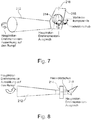
- FIGS. 7 and 8 clarify the construction and operation of a helicopter according to the invention, which is provided with a rotatable around the vertical axis, shrouded tail rotor.
- Fig. 7 shows the tail boom of the invention, in which the tail rotor thrust has a lateral component, whereas in the example of Fig. 8 the balance of the main rotor torque is effected by a rudder.
- a tail boom 212 of a helicopter has a shrouded tail rotor 214 which is rotatable about a vertical axis 216 of the helicopter so as to provide a propulsion component for propulsion of the helicopter, but also a lateral component for balancing the helicopter originating from the main rotor Torque.
- the jacketed tail rotor 214 can travel as far as the vertical axis 216 (FIG. Fig. 7 ) are rotated to produce a pure propulsion component through the tail rotor thrust.
- the compensation of the caused by the main rotor torque is effected by appropriate adjustment of a rudder 218 in cruising flight.
Description
- Die Erfindung betrifft ein Hybridantriebssystem für Flugzeuge, insbesondere Hubschrauber, sowie Hubschrauber mit einem derartigen Hybridantriebssystem.
- Herkömmlich werden Hubschrauber meist durch eine oder mehrere Gasturbinen angetrieben, wobei die hohe Drehzahl der Gasturbine durch ein Getriebe reduziert werden muss, von welchem aus mechanisch die Rotoren des Hubschraubers angetrieben werden, etwa ein Hauptrotor und ein Heckrotor. Ein derartiges Getriebe stellt offensichtlich hohe Anforderungen an die Ausfallsicherheit und ist daher entsprechend kompliziert, schwer und kostenaufwändig.
- Aus der
DE 10 2006 056 354 A1 ist ein Hybridantrieb für Flugzeuge bekannt, der eine Gasturbine zum Erzeugen einer ersten Antriebsenergie und einen Elektromotor zum Erzeugen einer zweiten Antriebsenergie aufweist. Die Gasturbine und der Elektromotor sind so ausgebildet, dass einer Antriebseinheit, beispielsweise einem Propeller, des Flugzeugs die erste und/oder die zweite Antriebsenergie bereitgestellt werden kann. Hierzu wird eine Kupplung zwischen Gasturbine und Elektromotor benötigt, oder eine erste Kupplung zwischen Gasturbine und Propellerwelle und eine zweite Kupplung zwischen Elektromotor und Propellerwelle. Für den Elektromotor können ein Brennstoffzellensystem und eine Batterie vorgesehen sein. - Aus der
DE 10 2006 056 356 A1 ist ein Antrieb mit mehreren Energiewandlern für ein Flugzeug bekannt, wobei jeder der Energiewandler als Gasturbine, Kolbenmotor oder Elektromotor ausgebildet sein kann. Auch hier ist eine Kupplung zwischen einem ersten und einem zweiten Energiewandler erforderlich, oder zwischen dem ersten und dem zweiten Energiewandler und einem Propeller. In diesem Zusammenhang wird auch erwähnt, dass für den Reiseflug oder in der Nähe eines Flugplatzes nur ein Elektromotor eingesetzt wird, wogegen bei Start und Landung zusätzlich ein Verbrennungsmotor benötigt wird. - In
WO 2008/086774 A2 wird ein Flugzeugpropellerantrieb mit einem Propeller, einem Motor und einem Antriebsstrang zwischen dem Propeller und dem Motor vorgeschlagen, bei welchem der Antriebsstrang einen Drehschwingungsdämpfer aufweist. Zwischen einem Dieselmotor und einer Getriebeeingangswelle kann eine Elektromaschine vorgesehen sein, welche als Generator geschaltet eine Batterie laden kann, und als Elektromotor geschaltet, und von der Batterie versorgt, Antrieb zusätzlich zum Dieselmotor bereitstellen kann. - Die
DE 10 2008 014 404 A1 beschreibt einen unbemannten Hubschrauber mit einem Hybridantrieb, bei welchem ein Brennstoffmotor einen Generator zur Stromerzeugung antreibt, und der Strom einen als Primärantrieb für Rotorblätter arbeitenden Elektromotor und/oder Pufferbatterien speist, wobei der Elektromotor auch mit Strom aus den Pufferbatterien gespeist werden kann. - Die
US 2009/0145998 A1 beschreibt einen Hubschrauber mit Hybridantriebssystem, das eine Gasturbine und einen von diesem über eine primäre Transmissionswelle antreibbaren Generator zur Erzeugung elektrischer Energie aufweist. Ein Elektromotor dient zum Antrieb eines Hauptrotors und kann wahlweise vom Generator oder einem Batteriepack versorgt werden, das elektrische Energie speichert. Ein oder mehrere weitere Rotoren werden über eine sekundäre Transmissionswelle angetrieben. - Die
US 4 605 185 beschreibt ein Starrflügelflugzeug mit einem Hybridantrieb, der einen Verbrennungsmotor und einen Generator aufweist, der Strom erzeugt für einen ersten Elektromotor, der einen ersten Propeller antreibt, und für einen zweiten Elektromotor, der einen zweiten Propeller antreibt. Für den Fall, dass der Verbrennungsmotor ausfällt und daher der Generator keinen Strom liefert, ist eine Notfallbatterie vorgesehen, die dann Strom für die beiden Elektromotoren liefert. - Die
US 2006/0048988 A1 beschreibt einen Hybridantrieb für Fahrzeuge, beispielsweise Land-, Wasser- oder Luftfahrzeuge, der einen Verbrennungsmotor und ein oder mehrere elektrische Maschinen aufweist, die beide als Elektromotor oder als Generator arbeiten können. Ein Akkumulator kann durch beide Generatoren aufgeladen werden. Im Betrieb kann beispielsweise der eine Elektromotor ein Automatikgetriebe eines Fahrzeuges antreiben, und der andere Elektromotor eine Ölpumpe des Fahrzeuges antreiben, um Hydraulikdruck für Aktuatoren bereitzustellen. - Die
US 4 554 989 beschreibt einen Hubschrauber mit einem Hybridantrieb, der einen Turbinenmotor aufweist, der einen Generator antreibt, der Strom an einen ersten Elektromotor liefert, der einen Hauptrotor antreibt, und an einen zweiten Elektromotor, der einen Heckrotor antreibt. - Die
FR 2 931 456 A1 US 2011/0073717 A1 ) beschreibt ein Starrflügelflugzeug, dessen Vortrieb durch Verbrennungsmotoren erfolgt. Elektrische Energie wird durch Solarzellen erzeugt und versorgt das Bordnetz des Flugzeugs. Ist überschüssige elektrische Energie vorhanden, so kann der Überschuss jeweils zur Versorgung einer elektrischen Maschine verwendet werden, die den jeweiligen Verbrennungsmotor unterstützt. - Die
WO 2009/025 231 A1 (oder die parallele, nicht vorveröffentlichteUS 2010/0127114171 A1 - Die
DE 1 581 060 B1 beschreibt einen Hubschrauber mit einem um eine senkrechte Achse schwenkbaren Heckrotor und einem Seitenleitwerk, wobei der Heckrotor, mit oder ohne Getriebe, in geringem Maße in Richtung seiner Drehachse gegen die Wirkung einer Schubmesseinrichtung verschiebbar ist, die den Schub des Heckrotors während dessen Schwenkung mittels einer auf dessen Blattwinkelstellvorrichtung wirkenden Regeleinrichtung auf einen konstanten, nahe bei Null liegenden Wert steuert. - Die der Erfindung zugrunde liegende Aufgabe besteht in der Bereitstellung eines alternativen hybriden Antriebs- und Energiesystems für Flugzeuge.
- Die Aufgabe wird durch die Gegenstände der unabhängigen Ansprüche gelöst. Weiterbildungen der Erfindung sind in den Unteransprüchen angegeben.
- Gemäß der Erfindung wird ein Hybridantriebssystem für Flugzeuge, insbesondere Hubschrauber, vorgeschlagen, mit zumindest einem Energieerzeugungsmodul mit einem Verbrennungsmotor und einem von diesem antreibbaren Generator zur Erzeugung elektrischer Energie, und zumindest einem Elektromotor zum (direkten oder indirekten) Antrieb eines Antriebsmittels des Flugzeugs. Antriebsmittel sind Haupt- und Heckrotor eines Hubschraubers. Der Elektromotor kann beispielsweise zusätzliche Leistung für einen herkömmlichen Antrieb eines Hubschraubers bereitstellen.
- Bei der Erfindung ist ein zweiter Elektromotor zum Antrieb eines zweiten Antriebsmittels des Flugzeugs vorgesehen, wobei das zweite Antriebsmittel ein Heckrotor eines Hubschraubers ist. Gemäß der Erfindung ist zumindest ein weiteres Energieerzeugungsmodul vorgesehen. Dieses kann eine Kombination aus einem zweiten Verbrennungsmotor und einem zweiten Generator sein; aber auch etwa eine Brennstoffzelleneinheit. Gemäß der Erfindung ist eine Speichereinheit für elektrische Energie vorgesehen, beispielsweise eine Batterieeinheit. Diese Speichereinheit kann so ausgelegt sein, dass es ermöglicht wird, dass Startvorgang und Steigflug eines Hubschraubers allein oder zu großen Teilen durch Energieversorgung von der Speichereinheit durchgeführt werden können, welche einen ersten Elektromotor zum Antrieb eines ersten Antriebsmittels und einen zweiten Elektromotor zum Antrieb eines zweiten Antriebsmittels des Hubschraubers antreibt. Zur weiteren Erhöhung der Sicherheit kann eine weitere, zusätzliche Speichereinheit für elektrische Energie, etwa eine Batterieeinheit, vorgesehen sein.
- Hierbei wird beim Start eines Hubschraubers dessen Verbrennungsmotor bzw. dessen Verbrennungsmotoren nur so weit hochgefahren, wie dies zur Erbringung der für den Start benötigten Gesamtleistung erforderlich ist. Dies führt zu erheblich verringerten Geräuschemissionen, im Vergleich zu einem herkömmlichen Hubschrauberantrieb, beim Start und entsprechend bei der Landung.
- Gemäß einer Ausführungsform der Erfindung ist das weitere Energieerzeugungsmodul als Brennstoffzelleneinheit ausgebildet. Diese kann anstelle eines aus Verbrennungsmotor und Generator bestehenden Energieerzeugungsmoduls eingesetzt werden, wenn dieses ausfällt, aber auch zusätzlich zu einem oder mehreren Energieerzeugungsmodulen.
- Weiterhin betrifft die Erfindung einen Hubschrauber mit einem Hybridantriebssystem, wie dies voranstehend geschildert wurde.
- Gemäß einer Ausführungsform der Erfindung ist ein derartiger Hubschrauber mit einem Hauptrotor und einem Heckrotor versehen, der als ummantelter Heckrotor ausgebildet ist, welcher um eine Hochachse des Hubschraubers drehbar ist.
- Der Heckrotor und der Heckrotorantrieb können um die Hochachse des Hubschraubers geschwenkt werden, um im Vorwärtsflug zum Vortrieb beizutragen. Hierzu kann der ummantelte Heckrotor oben und unten drehbar gelagert und mit zumindest einem Verstell-Aktuator ausgerüstet sein.
- Um weiterhin den Hauptrotor-Drehmomentenausgleich zu gewährleisten, wird der Heckrotor nur so weit gedreht, dass noch eine ausreichend lateral wirkende Schubkomponente übrig bleibt.
- Damit der ummantelte Heckrotor so weit um die Hochachse gedreht werden kann, dass er nur Vortrieb in Flugrichtung erzeugt, kann ein Seitenruder vorgesehen sein, welches den Drehmomentenausgleich im Vorwärtsflug übernimmt.
- Weiterhin betrifft die Erfindung ein Verfahren zum Steuern eines Hybridantriebssystems bzw. zum Steuern eines Hubschraubers mit einem derartigen Hybridantriebssystem gemäß der Erfindung, bei welchem bei erhöhtem Leistungsbedarf dem einen Energieerzeugungsmodul zusätzlich das weitere Energieerzeugungsmodul und/oder die Speichereinheit für elektrische Energie zugeschaltet wird.
- Bereits mit zwei Energieerzeugungsmodulen aus jeweils einem Verbrennungsmotor und einem Generator besteht Redundanz, welche durch die Speichereinheit für elektrische Energie noch erhöht wird. Für einen noch weiter erhöhten Leistungsbedarf und/oder noch weiter erhöhte Redundanz sind ein weiteres, zusätzliches Energieerzeugungsmodul (Verbrennungsmotor/Generatur) und eine zusätzliche Speichereinheit für elektrische Energie vorgesehen.
- Gemäß einer Ausführungsform der Erfindung wird in der Start- und der Landephase des Flugzeugs der zumindest eine Elektromotor nur von der Speichereinheit für elektrische Energie versorgt. Dies sorgt für geringere Lärmemissionen im Vergleich zu einem herkömmlichen Flugzeug- oder Hubschrauberantrieb.
- Gemäß einer Ausführungsform der Erfindung kann zur Sicherheit in der Start- und der Landephase des Flugzeugs der Verbrennungsmotor im Leerlauf oder erheblich unterhalb seiner Nennleistung im Betrieb sein.
- Gemäß einer Ausführungsform der Erfindung wird zum Steuern eines Hubschraubers dessen Heckrotor so weit um die Hochachse gedreht, dass eine laterale Schubkomponente des (ummantelten) Heckrotors das durch den Hauptrotor hervorgerufene Gierdrehmoment ausgleicht. Hierdurch stellt der Heckrotor eine laterale Schubkomponente zum Ausgleich des durch den Hauptrotor hervorgerufenen Gierdrehmoments zur Verfügung, und darüber hinaus die Schubkomponente in Vorwärtsrichtung (Flugrichtung).
- Gemäß einer Ausführungsfrom der Erfindung kann jedoch beim Steuern eines Hubschraubers so vorgegangen werden, dass der Heckrotor so weit um die Hochachse gedreht wird, dass der Heckrotorschub in Richtung der Längsachse des Hubschraubers nach hinten gerichtet ist, und das durch den Hauptrotor hervorgerufene Gierdrehmoment durch entsprechende Einstellung des Seitenruders ausgeglichen wird. Dies sorgt für eine optimale Unterstützung des Vortriebs durch den Heckrotor.
- Weiterhin wird dadurch, dass ein nicht unerheblicher Anteil des Vortriebs des Hubschraubers durch den Heckrotor erreicht wird, die Lärmemissionsquelle vom Kabinenbereich (Hauptrotor) des Hubschraubers weiter nach hinten zum Heckrotor hin verlagert, wodurch die Lärm- und Geräuschbelastung in der Kabine des Hubschraubers verringert wird.
- Es zeigt:
-
FIG. 1 eine schematische Darstellung eines Mild-Hybridantriebssystems zur Erläuterung der Erfindung; -
FIG. 2 eine schematische Darstellung eines Hybridantriebssystems zur Erläuterung der Erfindung mit einem Energieerzeugungsmodul; -
FIG. 3 eine schematische Darstellung eines Hybridantriebssystems gemäß der Erfindung mit zwei Energieerzeugungsmodulen; -
FIG. 4 eine schematische Darstellung eines Hybridantriebssystems gemäß der Erfindung, bei welchem ein Haupt- und ein Heckrotor jeweils über eine Kombination aus Elektromotor und Getriebe angetrieben werden; -
FIG. 5 eine schematische Darstellung eines Hybridantriebssystems gemäß der Erfindung mit einem ersten Energieerzeugungsmodul mit einem Verbrennungsmotor und einem von diesem antreibbaren Generator, sowie mit einem zweiten, als Brennstoffzellensystem ausgebildeten Energieerzeugungsmodul; -
FIG. 6 eine schematische Darstellung des modularen Aufbaus des Hybridantriebssystems gemäß der Erfindung für einen Hubschrauber; -
FIG. 7 eine Seitenansicht auf einen Heckausleger eines Hubschraubers gemäß der Erfindung; und -
FIG. 8 eine Aufsicht auf den Heckausleger eines Hubschraubers mit einem beweglichen Seitenruder. - Die Darstellungen in den Figuren sind schematisch und nicht maßstäblich.
- Für gleiche oder ähnliche Elemente werden gleiche oder entsprechende Bezugsziffern verwendet.
-
Fig. 1 zeigt schematisch das Hybridantriebssystem für Flugzeuge, insbesondere Hubschrauber. Oberhalb der gestrichelten Linie L ist bei (a) ein an sich herkömmlicher Hubschrauberantrieb dargestellt, mit einem Verbrennungsmotor 10, der über eine Welle 12 einen Eingang E1 eines Getriebes 14 antreibt, wobei dann das Getriebe über einen Ausgang A1 eine Welle 16 und mit dieser einen Hauptrotor 18 antreibt, und über einen weiteren Ausgang A2 über eine Welle 20 einen Heckrotor 22 des Hubschraubers. - Weiterhin ist unterhalb der gestrichelten Linie L bei (b) in
Fig. 1 ein vom Verbrennungsmotor 10 angetriebener Generator 26 vorgesehen. Dieser könnte allerdings auch über einen weiteren (nicht dargestellten) Verbrennungsmotor angetrieben werden. Generator 24 liefert über eine Leitung 26 Strom an einen Elektromotor 30, der über eine Welle 36 einen Eingang E2 des Getriebes 14 antreibt und so zusätzliche Leistung zur Verfügung stellt. - Weiterhin kann der Generator 24 über eine Leitung 28 eine Batterie 32 aufladen, und kann die Batterie 32 über eine Leitung 34 den Elektromotor 30 mit Strom versorgen, etwa zusätzlich zur Stromversorgung durch den Generator 24, oder alternativ hierzu.
- In
Fig. 2 ist ein Hybridantriebssystem für Hubschrauber dargestellt, das einen Verbrennungsmotor 42 aufweist, der über eine Welle 44 einen Generator 46 antreibt. Generator 46 versorgt über eine Leitung 56 einen ersten Elektromotor 60 mit Strom, der über eine Welle 62 einen Hauptrotor 64 des Hubschraubers antreibt. Weiterhin versorgt der Generator über eine Leitung 48 einen zweiten Elektromotor 50 mit Strom, der über eine Welle 52 einen Heckrotor 54 des Hubschraubers antreibt. - Darüber hinaus kann der Generator 46 über eine Leitung 66 eine Batterie (einen Batteriesatz) 68 aufladen. Dies kann beispielsweise im Reiseflug des Hubschraubers erfolgen, wenn der Leistungsbedarf für den Elektromotor 1 des Hauptrotors 64 nicht so groß ist wie beim Start.
- Weiterhin kann die Batterie 60 über eine Leitung 74, einen Schalter S1 und eine Leitung 76 den ersten Elektromotor 60 mit Strom versorgen, zusätzlich zur Stromversorgung durch den Generator 46, oder alternativ zu dieser. Entsprechend kann die Batterie 68 über eine Leitung 70 und einen Schalter S2 und eine weitere Leitung 72 den zweiten Elektromotor 2 für den Heckrotor 64 mit Strom versorgen.
- In
Fig. 3 ist ein Hybridantriebssystem für einen Hubschrauber dargestellt, bei welchem ein erstes Energieerzeugungsmodul mit Verbrennungsmotor 82 und Generator 86 sowie ein zweites Energieerzeugungsmodul mit einem zweiten Verbrennungsmotor 116 und einem zweiten Generator 120 vorgesehen sind. Diese beiden Energieerzeugungsmodule können zusammen oder alternativ betrieben werden, wenn sie eine entsprechende, für den Betrieb des Hubschraubers erforderliche Leistung aufbringen. Es kann aber auch beispielsweise bei bestimmten Betriebszuständen des Hubschraubers mehr Leistung von dem ersten Energieerzeugungsmodul 82, 86 aufgebracht werden, und bei anderen Betriebszuständen mehr Leistung von dem zweiten Energieerzeugungsmodul 116, 120. - Der erste Generator 86 liefert über eine Leitung 88 Strom an einen insgesamt mit dem Bezugszeichen 90 bezeichneten Batteriesatz, der einzelne Batterieuntergruppen 92, 94, 96, 98, 100 aufweist, die in beliebigen Kombinationen mit einem der Eingänge (Leitungen 88, 122) bzw. Ausgänge (Leitungen 104, 126) der Batterieeinheit 90 verbunden werden können.
- Der erste Generator 86 kann über eine Leitung 88 und einen Schalter S1 sowie eine Leitung 104 einen ersten Elektromotor 106 versorgen, der über eine Welle 108 den Hauptrotor 110 des Hubschraubers antreibt.
- Der Generator 86 kann jedoch auch über die Leitung 102 und einen Schalter S3 und Leitungen 112, 126 einen zweiten Elektromotor 128 versorgen, der über eine Welle 130 den Heckrotor 132 des Hubschraubers antreibt.
- Entsprechendes gilt für den zweiten Generator 120, der über die Leitung 122 und eine Leitung 124 und einen Schalter S2 sowie die Leitung 126 den zweiten Elektromotor 128 mit Strom versorgen kann, oder über die Leitung 124 und einen Schalter S4 sowie eine Leitung 114 und die Leitung 104 den ersten Elektromotor 106.
- Insgesamt weist daher das in
Fig. 3 dargestellte Hybridantriebssystem eine hohe Redundanz auf, infolge des ersten Energieerzeugungsmoduls 82, 86, des zweiten Energieerzeugungsmoduls 116, 120, und der Batterieeinheit 90, welche einen Energiezwischenspeicher und damit ein weiteres Energieerzeugungsmodul für den ersten Elektromotor 106 und/oder den zweiten Elektromotor 128 darstellt. - Jedes Energieerzeugungsmodul in
Fig. 3 kann an einem geeigneten Ort im Hubschrauber angeordnet sein, unabhängig von dem ersten Elektromotor 106 zum Antrieb des Hauptrotors 110 und dem zweiten Elektromotor 128 für den Heckrotor 132. So können etwa die beiden Energieerzeugungsmodule unterhalb des Kabinenbodens eines Hubschraubers angeordnet sein, ebenso wie die Batterieeinheit 90. Dies sorgt dafür, dass sich nicht wie bei herkömmlichen Hubschrauberantrieben relativ schwere Komponenten relativ weit oben im Hubschrauber befinden müssen, sondern der Schwerpunkt des Hubschraubers nach unten verlagert werden kann. - Bezüglich der Verbrennungsmotoren wird darauf hingewiesen, dass diese vorzugsweise als Wankelmotoren ausgebildet sind, obwohl auch Kolbenmotoren wie etwa Dieselmotoren eingesetzt werden können. Grundsätzlich kann auch eine Gasturbine als Verbrennungsmotor eingesetzt werden.
- Herkömmliche Hubschrauberturbotriebwerke weisen zwei Turbinenstufen auf, die erste zum Antrieb des Triebwerksverdichters und die zweite zur Erzeugung des Rotordrehmoments. Die sehr hohe Turbinendrehzahl muss mittels Getrieben auf die Rotordrehzahl untersetzt werden. Wird die Turbine dagegen zur Energieerzeugung, d.h. zum Antrieb eines Generators eingesetzt, so können zweite Turbinenstufe und Reduktionsgetriebe wegfallen. Die erste treibt zugleich Verdichter und Generator an.
- Die bei der Erfindung verwendeten Elektromotoren sind vorzugsweise als trägheitsarmer Direktantrieb hoher Leistungsdichte ausgebildet, wie in der
DE 10 2007 013 732 A1 beschrieben, also als elektrische Maschinen mit Permanenterregung, die sich durch hohes spezifisches Drehmoment und Leistungsdichte sowie ein geringes Trägheitsmoment insbesondere für Direktantrieb der Rotoren des Hubschraubers eignen. - Das erfindungsgemäße Konzept für ein Hybridantriebssystem eignet sich besonders gut dafür, einen Hubschrauber dadurch an eine erhöhte Leistungsanforderung anzupassen, dass ein zusätzliches Energieerzeugungsmodul aus Verbrennungsmotor und Generator vorgesehen wird, oder eine zusätzliche Batterieeinheit.
- Dieses modulare Konzept eignet sich auch besonders gut dazu, Familien von Hubschraubern unterschiedlicher Größe mit unterschiedlichen Leistungsanforderungen anzutreiben. Je nach Erfordernis werden nämlich standardisierte Energieerzeugungsmodule (Verbrennungsmotor/Generator) in der erforderlichen Anzahl eingesetzt. Dies stellt ein so genanntes Familienkonzept dar, das erhebliche Auswirkungen auf die Senkung von Entwicklungskosten einer Hubschrauberfamilie hat.
- Insbesondere ermöglicht das in den
Fig. 2 und 3 dargestellte Hybridantriebssystem einen "getriebelosen" Hubschrauber, der ohne das bei einem herkömmlichen Hubschrauberantrieb erforderliche Getriebe auskommt. - Sollte jedoch zwischen dem Elektromotor für den Hauptrotor und/oder dem Elektromotor für den Heckrotor ein Getriebe erforderlich sein, so kann dieses gemäß
Fig. 4 in der Nähe des Elektromotors und des betreffenden Rotors vorgesehen werden.Fig. 4 zeigt einen ersten Elektromotor 142, der über eine Welle 144 ein erstes Getriebe 146 antreibt, das wiederum über eine Welle 148 einen Hauptrotor 150 eines Hubschraubers antreibt. Entsprechend treibt ein zweiter Elektromotor 152 über eine Welle 154 ein zweites Getriebe 156 an, das über eine Welle 158 einen Heckrotor 160 des Hubschraubers antreibt. - In
Fig. 3 sind die beiden Energieerzeugungsmodule 82, 86 und 116, 120 gleichartig ausgebildet. Sie können aber auch verschieden sein, wie dies inFig. 5 gezeigt ist. Ein Verbrennungsmotor 162 treibt über eine Welle 164 einen Generator 166 an, der über eine Leitung 168 Strom abgibt, welche der Leitung 88 inFig. 3 entspricht. Ein zweites Energieerzeugungsmodul inFig. 5 besteht aus einer Brennstoffzelle 170, die über eine Leitung 172 Strom abgibt, welche der Leitung 122 inFig. 3 entspricht. -
Fig. 6 verdeutlicht nochmals den modularen Aufbau des Hybridantriebssystems für einen Hubschrauber 202 gemäß der Erfindung. Ein erstes Energieerzeugungsmodul besteht aus einem Wankelmotor 182 und einem Generator 84, ein zweites Energieerzeugungsmodul aus einem Wankelmotor 192 und einem Generator 194, und ein drittes Energieerzeugungsmodul aus einem Wankelmotor 196 und einem Generator 198. Jedes dieser Energieerzeugungsmodule bzw. dessen entsprechender Generator 184, 194, 198 ist an ein zentrales Energiesteuersystem 186 angeschlossen. Dieses sorgt beispielsweise für das Aufladen einer Batterie 200 bzw. die Entnahme elektrischer Energie aus dieser. Das Energiesteuersystem 186 liefert elektrische Energie über einen Inverter 188 an einen ersten Elektromotor 190 eines Hauptrotors 204 bzw. einen zweiten Elektromotor 190 eines Heckrotors 206 des Hubschraubers 202. - In diesem Zusammenhang wird darauf hingewiesen, dass bei den sich zukünftig immer mehr durchsetzenden Fly-by-Wire-Steuerungen nach dem gegenwärtigen Stand der Technik Bewegungssensoren an den Steuerorganen die Pilotensteuerabsicht erfassen und diese an den zentralen Bordcomputer melden. Dieser setzt die Signale in elektrische Ansteuerungsspannungen für die Schub-Einstellung von Haupt- und Heckrotor um.
- Bei einem Hubschrauber mit einem Hybridantrieb gemäß der Erfindung erfolgt dies in vorteilhafter Weise elektrisch, beim Hauptrotor z.B. in Form elektrischer Drehspindeln unterhalb der die Blatteinstellwinkel definierenden Taumelscheiben, oder durch piezoelektrisch betriebene Servoklappen an den Blatthinterkanten, oder durch eine Kombination beider Komponenten, und beim Heckrotor z.B. durch ebensolche Spindeln unterhalb der für den Blattanstellwinkel verantwortlichen Schiebehülse, oder durch Variation der Heckrotordrehzahl.
- Da alle diese Steuervorgänge elektrisch erfolgen, und auch die Rotoren jeweils über einen Elektromotor angetrieben werden, kann der Hubschrauber insgesamt mit einer einheitlichen Energieform betrieben werden.
- Bei der vorgenannten Drehzahlvariation sowie beim Schwenken des Heckrotors ist ohnehin ein elektrischer Antrieb erforderlich. Ein hier ebenfalls möglicher Hydraulikantrieb würde dagegen die Forderung nach Energieeinheitlichkeit verletzen.
- Die
Fig. 7 und 8 verdeutlichen die Bau- und Betriebsweise eines Hubschraubers gemäß der Erfindung, der mit einem um die Hochachse drehbaren, ummantelten Heckrotor versehen ist.Fig. 7 zeigt den Heckausleger der Erfindung, bei welcher der Heckrotorschub eine laterale Komponente aufweist, wogegen bei dem Beispiel vonFig. 8 der Ausgleich des Hauptrotor-Drehmoments durch ein Seitenruder bewirkt wird. - Wie in
Fig. 7 dargestellt, weist ein Heckausleger 212 eines Hubschraubers einen ummantelten Heckrotor 214 auf, der um eine Hochachse 216 des Hubschraubers drehbar ist, so dass er eine Vortriebskomponente zum Vortrieb des Hubschraubers zur Verfügung stellt, aber auch eine laterale Komponente für den Ausgleich des von dem Hauptrotor hervorgerufenen Drehmoments.Bei dem inFig. 8 dargestelltem Beispiel dagegen kann zumindest im Vorwärtsflug (Reiseflug) des Hubschraubers der ummantelte Heckrotor 214 so weit um die Hochachse 216 (Fig. 7 ) gedreht werden, dass er eine reine Vortriebskomponente durch den Heckrotorschub erzeugt. Der Ausgleich des von dem Hauptrotor hervorgerufenen Drehmoments erfolgt durch entsprechende Verstellung eines Seitenruders 218 im Reiseflug. -
- L
- gestrichelte Linie
- 10
- Verbrennungsmotor
- 12
- Welle
- 14
- Getriebe
- 16
- Welle
- 18
- Hauptrotor
- 20
- Welle
- 22
- Heckrotor
- 24
- Generator
- 26
- Leitung
- 28
- Leitung
- 30
- Elektromotor
- 32
- Batterieeinheit
- 34
- Leitung
- 36
- Welle
- A1, A2
- Ausgänge von 14
- E1, E2
- Eingänge
- 42
- Verbrennungsmotor
- 44
- Welle
- 46
- Generator
- 48
- Leitung
- 50
- Elektromotor 2
- 52
- Welle
- 54
- Heckrotor
- 56
- Leitung
- 60
- Elektromotor 1
- 62
- Welle
- 64
- Hauptrotor
- 66
- Leitung
- 68
- Batterieeinheit
- 70
- Leitung
- 72
- Leitung
- 74
- Leitung
- 76
- Leitung
- 51, 52
- Schalter
- 82
- Verbrennungsmotor 1
- 84
- Welle
- 86
- Generator 1
- 88
- Leitung
- 90
- Batterieeinheit
- 92
- Batterie
- 94
- Batterie
- 96
- Batterie
- 98
- Batterie
- 100
- Batterie
- 102
- Leitung
- 104
- Leitung
- 106
- Elektromotor 1
- 108
- Welle
- 110
- Hauptrotor
- 112
- Leitung
- 114
- Leitung
- 116
- Verbrennungsmotor 2
- 118
- Welle
- 120
- Generator 2
- 122
- Leitung
- 124
- Leitung
- 126
- Leitung
- 128
- Elektromotor 2
- 130
- Welle
- 132
- Heckrotor
- 142
- Elektromotor 1
- 144
- Leitung
- 146
- Getriebe 1
- 148
- Welle
- 150
- Hauptrotor
- 152
- Elektromotor 2
- 154
- Leitung
- 156
- Getriebe 2
- 158
- Welle
- 160
- Heckrotor
- 162
- Verbrennungsmotor 1
- 164
- Welle
- 166
- Generator 1
- 168
- Leitung
- 170
- Brennstoffzelleneinheit
- 172
- Leitung
- 182
- Verbrennungsmotor
- 184
- Generator
- 186
- Energiesteuersystem
- 188
- Inverter (Wechselrichter)
- 190
- Elektromotor
- 192
- Verbrennungsmotor
- 194
- Generator
- 196
- Verbrennungsmotor
- 198
- Generator
- 200
- Batterieeinheit
- 202
- Hubschrauber
- 204
- Hauptrotor
- 206
- Heckrotor
- 212
- Heckausleger
- 214
- Ummantelter Heckrotor
- 216
- Hochachse
- 218
- Seitenruder
Claims (11)
- Hybridantriebssystem für einen Hubschrauber mit(a) einem ersten Energieerzeugungsmodul (82, 86), mit einem Verbrennungsmotor (82) und einem von diesem antreibbaren Generator (86) zur Erzeugung elektrischer Energie;(b) einem ersten Elektromotor (106) zum Antrieb eines Hauptrotors (110) des Hubschraubers;(c) einem zweiten Elektromotor (128) zum Antrieb eines Heckrotors (132) des Hubschraubers;(d) zumindest einem weiteren Energieerzeugungsmodul (116, 120; 170); und(e) einer Speichereinheit (90) für elektrische Energie;
dadurch gekennzeichnet, dass das Hybridantriebssystem weiterhin aufweist(f) einen Heckrotor, der oben und unten drehbar gelagert ist und so weit um eine Hochachse des Hubschraubers drehbar ist, dass ein durch den Hauptrotor hervorgerufenes Gierdrehmoment durch eine laterale Schubkomponente des Heckrotors ausgleichbar ist. - Hybridantriebssystem nach Anspruch 1,
dadurch gekennzeichnet, dass das erste Energieerzeugungsmodul (82, 86) und das weitere Energieerzeugungsmodul (116, 120) gleich oder gleichartig ausgebildet sind. - Hybridantriebssystem nach Anspruch 1,
dadurch gekennzeichnet, dass das weitere Energieerzeugungsmodul als Brennstoffzelleneinheit (170) ausgebildet ist. - Hubschrauber dadurch gekennzeichnet, dass es mit einem Hybridantriebssystem nach einem der Ansprüche 1 bis 3 ausgestattet ist.
- Hubschrauber (202) nach Anspruch 4, dadurch gekennzeichnet, dass der Heckrotor (206) als ummantelter Heckrotor ausgebildet ist.
- Hubschrauber nach Anspruch 5, gekennzeichnet durch ein Seitenruder (218).
- Verfahren zum Steuern eines Hybridantriebssystems nach einem der Ansprüche 1 bis 3 oder zum Steuern eines Hubschraubers nach einem der Ansprüche 4 bis 6 mit einem derartigen Hybridantriebssystem,
dadurch gekennzeichnet, dass bei erhöhtem Leistungsbedarf dem ersten Energieerzeugungsmodul (82, 86) zusätzlich das weitere Energieerzeugungsmodul (116, 120) und/oder die Speichereinheit (90) für elektrische Energie zugeschaltet wird. - Verfahren nach Anspruch 7,
dadurch gekennzeichnet, dass in der Start- und der Landephase des Hubschraubers der erste Elektromotor (106) nur von der Speichereinheit (90) für elektrische Energie versorgt wird. - Verfahren nach Anspruch 8,
dadurch gekennzeichnet, dass in der Start- und Landephase des Hubschraubers der Verbrennungsmotor (82) im Leerlauf läuft. - Verfahren zum Steuern eines Hubschraubers nach einem der Ansprüche 7 bis 9,
dadurch gekennzeichnet, dass der Heckrotor (206) so weit um die Hochachse (216) gedreht wird, dass eine laterale Schubkomponente des Heckrotors (206) das durch den Hauptrotor hervorgerufene Gierdrehmoment ausgleicht. - Verfahren zum Steuern eines Hubschraubers nach einem der Ansprüche 7 bis 9,
dadurch gekennzeichnet, dass der Heckrotor (206) so weit um die Hochachse (216) gedreht wird, dass der Heckrotorschub in Richtung der Längsachse des Hubschraubers nach hinten gerichtet ist, und das durch den Hauptrotor hervorgerufene Gierdrehmoment durch entsprechende Einstellungen des Seitenruders (218) ausgeglichen wird.
Applications Claiming Priority (2)
| Application Number | Priority Date | Filing Date | Title |
|---|---|---|---|
| DE102010021026A DE102010021026A1 (de) | 2010-05-19 | 2010-05-19 | Hybrides Antriebs- und Energiesystem für Fluggeräte |
| PCT/EP2011/058125 WO2011144692A2 (de) | 2010-05-19 | 2011-05-19 | Hybrides antriebs- und energiesystem für fluggeräte |
Publications (2)
| Publication Number | Publication Date |
|---|---|
| EP2571763A2 EP2571763A2 (de) | 2013-03-27 |
| EP2571763B1 true EP2571763B1 (de) | 2017-05-17 |
Family
ID=44119127
Family Applications (1)
| Application Number | Title | Priority Date | Filing Date |
|---|---|---|---|
| EP11720491.7A Active EP2571763B1 (de) | 2010-05-19 | 2011-05-19 | Hybrides antriebs- und energiesystem für fluggeräte |
Country Status (6)
| Country | Link |
|---|---|
| US (1) | US9194285B2 (de) |
| EP (1) | EP2571763B1 (de) |
| KR (1) | KR101501978B1 (de) |
| CN (1) | CN102971216B (de) |
| DE (1) | DE102010021026A1 (de) |
| WO (1) | WO2011144692A2 (de) |
Cited By (1)
| Publication number | Priority date | Publication date | Assignee | Title |
|---|---|---|---|---|
| EP3620381B1 (de) * | 2018-09-06 | 2022-07-06 | Pratt & Whitney Canada Corp. | Hybrides elektrisches flugzeug und verfahren zum betrieb |
Families Citing this family (102)
| Publication number | Priority date | Publication date | Assignee | Title |
|---|---|---|---|---|
| US8469306B2 (en) * | 2009-01-27 | 2013-06-25 | Ira F. Kuhn, Jr. | Purebred and hybrid electric VTOL tilt rotor aircraft |
| GB201104733D0 (en) * | 2011-03-21 | 2011-05-04 | Lee Christopher J | Charging unit for hybrid electrically powered aircraft |
| DE102012209803A1 (de) * | 2012-06-12 | 2013-12-12 | Siemens Aktiengesellschaft | Verfahren zum Bereitstellen einer vorbestimmten Antriebscharakteristik in einem Flugzeug und zugehörige Antriebsvorrichtung |
| DE102012209807A1 (de) * | 2012-06-12 | 2013-12-12 | Siemens Aktiengesellschaft | Flugzeug und Verfahren zum Herstellen eines Flugzeugs |
| US8939399B2 (en) * | 2012-07-31 | 2015-01-27 | Textron Innovations Inc. | System and method of augmenting power in a rotorcraft |
| US9026274B2 (en) * | 2012-08-31 | 2015-05-05 | Sikorsky Aircraft Corporation | Method of controlling an electric propulsion system |
| EP2971594B1 (de) * | 2013-03-14 | 2020-01-08 | Rolls-Royce Corporation | Steuerung eines hybriden turboelektrischen luftantriebssystems |
| US9180964B2 (en) * | 2013-03-15 | 2015-11-10 | Bell Helicopter Textron Inc. | Autorotative enhancement system |
| CN103359284A (zh) * | 2013-06-29 | 2013-10-23 | 天津大学 | 一种油电混合动力四旋翼无人飞行器 |
| US9169027B2 (en) | 2013-10-04 | 2015-10-27 | Sikorsky Aircraft Corporation | Electrified rotorcraft |
| CN103580280B (zh) * | 2013-11-20 | 2015-09-09 | 上海交通大学 | 一种四旋翼小型直升机混合能源供给系统 |
| DE102014002071A1 (de) | 2014-02-18 | 2015-08-20 | Airbus Defence and Space GmbH | Elektromaschine für Luftfahrzeug-Direktantrieb, insbesondere für Hubschrauber-Direktantrieb, Verwendungen davon sowie Herstellverfahren dafür |
| DE102014003956A1 (de) | 2014-03-20 | 2015-09-24 | Airbus Defence and Space GmbH | Elektrische Maschine. insbesondere für Luftfahrzeuge |
| US20160023773A1 (en) * | 2014-07-23 | 2016-01-28 | Hamilton Sundstrand Corporation | Hybrid electric pulsed-power propulsion system for aircraft |
| IL233902B (en) | 2014-07-31 | 2020-07-30 | Israel Aerospace Ind Ltd | egnition system |
| AU2015361236A1 (en) | 2014-08-29 | 2017-04-20 | Zunum Aero, Inc. | System and methods for implementing regional air transit network using hybrid-electric aircraft |
| US20160257416A1 (en) * | 2014-09-02 | 2016-09-08 | Hamilton Sundstrand Corporation | Propulsion system |
| CN104242435B (zh) * | 2014-09-09 | 2017-05-24 | 深圳清华大学研究院 | 无人机的供电系统及无人机 |
| US10759280B2 (en) * | 2014-09-23 | 2020-09-01 | Sikorsky Aircraft Corporation | Hybrid electric power drive system for a rotorcraft |
| FR3027286B1 (fr) * | 2014-10-20 | 2018-01-05 | Safran Helicopter Engines | Systeme propulsif hybride d'un aeronef multi-moteur |
| JP6425968B2 (ja) * | 2014-10-29 | 2018-11-21 | ヤンマー株式会社 | ヘリコプター |
| JP6425969B2 (ja) * | 2014-10-29 | 2018-11-21 | ヤンマー株式会社 | ヘリコプター |
| CN104354870B (zh) * | 2014-10-29 | 2017-06-06 | 深圳清华大学研究院 | 用于混合动力直升机的电动直驱式尾桨组件、直升机 |
| DE102014018243A1 (de) * | 2014-12-04 | 2016-06-09 | Wolf-Günter Gfrörer | Hubschrauber mit Hybridantrieb |
| EP3031730B1 (de) * | 2014-12-12 | 2019-09-04 | Airbus (Sas) | Luftfahrzeug und Verfahren zur Ausstattung eines solchen Luftfahrzeugs |
| EP3034834B1 (de) * | 2014-12-16 | 2019-04-10 | Airbus (Sas) | Steuerungsverfahren einer Leistungsanforderung zum Betrieb eines unbemannten Luftfahrzeugs, das mit einem Verbrennungsmotor ausgestattet ist |
| CN104670504B (zh) * | 2015-02-13 | 2016-06-29 | 吉林大学 | 油/光/电多动力源固定翼飞行器 |
| US20160304214A1 (en) * | 2015-04-20 | 2016-10-20 | Hamilton Sundstrand Corporation | Emergency power sources for propulsion systems |
| JP6730842B2 (ja) * | 2015-05-05 | 2020-07-29 | ロールス−ロイス コーポレイション | 航空機の推進およびリフトのための電気直結駆動装置 |
| US10112697B2 (en) * | 2015-05-11 | 2018-10-30 | Sikorsky Aircraft Corporation | Aircraft with thrust vectoring tail |
| KR101713800B1 (ko) * | 2015-06-15 | 2017-03-08 | 권오병 | 항공기의 하이브리드 구동장치 |
| CN105173092A (zh) * | 2015-07-15 | 2015-12-23 | 北京虹湾威鹏信息技术有限公司 | 一种混合动力多轴旋翼无人机 |
| KR101615486B1 (ko) * | 2015-07-17 | 2016-04-26 | 주식회사 한국카본 | 하이브리드 전기 추진시스템을 이용하는 수직이착륙 항공기 |
| DE102015213580A1 (de) * | 2015-07-20 | 2017-01-26 | Siemens Aktiengesellschaft | Propellerantrieb und Fahrzeug, insbesondere Flugzeug |
| FR3039614B1 (fr) * | 2015-07-31 | 2018-05-04 | Airbus Helicopters | Installation motrice hybride pour aeronef a voilure tournante bimoteur |
| US11148822B2 (en) * | 2015-09-15 | 2021-10-19 | Sikorsky Aircraft Corporation | Drive system arrangement for rotorcraft |
| EP3162713B1 (de) | 2015-10-30 | 2018-08-01 | Sikorsky Aircraft Corporation | Leistungsausgleichssteuergerät |
| US10774741B2 (en) * | 2016-01-26 | 2020-09-15 | General Electric Company | Hybrid propulsion system for a gas turbine engine including a fuel cell |
| CN105752344B (zh) * | 2016-03-15 | 2017-12-15 | 电子科技大学 | 一种用于倾转旋翼飞行器的插电式混合动力驱动装置 |
| CN105799941B (zh) * | 2016-03-25 | 2018-11-20 | 广州市香港科大霍英东研究院 | 一种适于无人机的小型油电混合动力系统及其控制方法 |
| CN105836141B (zh) * | 2016-04-12 | 2018-01-12 | 电子科技大学 | 一种混合动力直升机驱动机构及驱动方法 |
| US10526085B2 (en) * | 2016-06-03 | 2020-01-07 | Bell Textron Inc. | Electric distributed propulsion anti-torque redundant power and control system |
| US10703471B2 (en) * | 2016-06-03 | 2020-07-07 | Bell Helicopter Textron Inc. | Anti-torque control using matrix of fixed blade pitch motor modules |
| US10377479B2 (en) | 2016-06-03 | 2019-08-13 | Bell Helicopter Textron Inc. | Variable directional thrust for helicopter tail anti-torque system |
| WO2018027002A1 (en) | 2016-08-05 | 2018-02-08 | Textron Aviation Inc. | Hybrid aircraft |
| US10017266B2 (en) * | 2016-09-22 | 2018-07-10 | Top Flight Technologies, Inc. | Power generation and distribution for vehicle propulsion |
| FR3056555B1 (fr) * | 2016-09-29 | 2018-12-07 | Safran Helicopter Engines | Systeme propulsif hybride pour aeronef a voilure tournante multirotor comprenant des moyens ameliores de conversion dc/ac |
| US10427780B2 (en) | 2016-10-20 | 2019-10-01 | Bell Helicopter Textron Inc. | Electric cold flow tipjet rotorcraft |
| CN106494625A (zh) * | 2016-11-02 | 2017-03-15 | 沈阳航空航天大学 | 一种并联式通用飞机气电混合动力系统 |
| CN106564603A (zh) * | 2016-11-02 | 2017-04-19 | 沈阳航空航天大学 | 一种串联式通用飞机气电混合动力系统 |
| DE102016224779B4 (de) * | 2016-12-13 | 2019-08-29 | Airbus Defence and Space GmbH | Elektrische Antriebsanordnung für ein Luftfahrzeug, Verfahren zu deren Betrieb sowie Luftfahrzeug |
| FR3060653B1 (fr) * | 2016-12-15 | 2019-05-24 | Safran Power Units | Unite de generation de puissance electrique non propulsive |
| US10723452B2 (en) | 2017-02-15 | 2020-07-28 | Sikorsky Aircraft Corporation | Engine systems for rotorcraft |
| US10604268B2 (en) * | 2017-02-22 | 2020-03-31 | Pratt & Whitney Canada Corp. | Autothrottle control for turboprop engines |
| US20180265206A1 (en) * | 2017-03-17 | 2018-09-20 | Hamilton Sundstrand Corporation | Variable speed ac bus powered tail cone boundary layer ingestion thruster |
| WO2018175349A1 (en) | 2017-03-19 | 2018-09-27 | Zunum Aero, Inc. | Hybrid-electric aircraft, and methods, apparatus and systems for facilitating same |
| CN107200118B (zh) * | 2017-04-20 | 2020-02-11 | 湖北工业大学 | 燃料电池植保无人直升机 |
| CA3063192A1 (en) * | 2017-05-10 | 2018-11-15 | Embry-Riddle Aeronautical University, Inc. | Systems and methods for noise mitigation for hybrid and electric aircraft |
| US11186185B2 (en) * | 2017-05-31 | 2021-11-30 | Textron Innovations Inc. | Rotor brake effect by using electric distributed anti-torque generators and opposing electric motor thrust to slow a main rotor |
| US10822100B2 (en) | 2017-06-26 | 2020-11-03 | General Electric Company | Hybrid electric propulsion system for an aircraft |
| US20190002117A1 (en) * | 2017-06-30 | 2019-01-03 | General Electric Company | Propulsion system for an aircraft |
| CN107628241A (zh) * | 2017-09-25 | 2018-01-26 | 安徽瓦尔特机械贸易有限公司 | 一种无人机混合动力系统 |
| US10676188B2 (en) * | 2017-10-04 | 2020-06-09 | Textron Innovations Inc. | Tiltrotor aircraft having a downwardly tiltable aft rotor |
| EP3501983B1 (de) * | 2017-12-22 | 2020-02-05 | LEONARDO S.p.A. | Anti-drehmomentsystem für einen hubschrauber und verfahren zur steuerung eines anti-drehmomentsystems für einen hubschrauber |
| CN108082500A (zh) * | 2018-01-29 | 2018-05-29 | 吉林大学 | 一种固定翼式混合动力飞行器驱动装置及驱动方法 |
| CN108313306B (zh) * | 2018-03-23 | 2024-04-05 | 中科灵动航空科技成都有限公司 | 一种旋翼无人机平台 |
| FR3079498B1 (fr) | 2018-03-30 | 2020-06-19 | Airbus Operations | Unite de propulsion a helice comprenant un moteur thermique et un moteur electrique et aeronef comportant une telle unite de propulsion a helice |
| FR3079819B1 (fr) * | 2018-04-10 | 2022-03-11 | Safran | Alimentation electrique des equipements non-propulsifs d'un aeronef |
| FR3080835B1 (fr) * | 2018-05-03 | 2021-04-09 | Safran Helicopter Engines | Systeme propulsif pour un helicoptere |
| FR3084318B1 (fr) | 2018-07-25 | 2020-06-26 | Airbus Helicopters | Procede et dispositif de gestion de l'energie d'une installation motrice hybride d'un aeronef multirotor |
| US10933980B2 (en) | 2018-08-03 | 2021-03-02 | Bell Helicopter Textron Inc. | Peak power use with pilot monitoring |
| US11283376B2 (en) | 2018-09-06 | 2022-03-22 | Pratt & Whitney Canada Corp | Hybrid electric propulsion system and method of operation |
| US11233470B2 (en) | 2018-09-06 | 2022-01-25 | Pratt & Whitney Canada Corp. | Synchronization of generator and electric motor in a hybrid electric aircraft propulsion system |
| JP7057264B2 (ja) * | 2018-11-02 | 2022-04-19 | 本田技研工業株式会社 | ハイブリッド飛行体 |
| US11225881B2 (en) * | 2018-11-08 | 2022-01-18 | Rolls-Royce North American Technologies, Inc. | Hybrid propulsion systems |
| US10759540B2 (en) * | 2018-11-08 | 2020-09-01 | Rolls-Royce North American Technologies, Inc. | Hybrid propulsion systems |
| US11159024B2 (en) | 2018-11-08 | 2021-10-26 | Rolls-Royce North American Technologies, Inc. | Electrical architecture for hybrid propulsion |
| US11370554B2 (en) | 2018-11-08 | 2022-06-28 | Rolls-Royce North American Technologies, Inc. | Hybrid propulsion systems |
| WO2020180368A2 (en) * | 2019-03-01 | 2020-09-10 | United Technologies Advanced Projects, Inc. | Aircraft having hybrid-electric propulsion system with electric storage located in fuselage |
| KR101970601B1 (ko) * | 2019-03-13 | 2019-04-19 | 문창모 | 하이브리드 전기 추진시스템을 이용하는 수직이착륙 항공기 |
| US11279477B2 (en) | 2019-03-19 | 2022-03-22 | Textron Innovations Inc. | Rotating electric distributed anti-torque fin |
| US11097836B2 (en) * | 2019-03-21 | 2021-08-24 | Textron Innovations Inc. | Vibration attenuation system for electric and hybrid electric vehicles |
| FR3094314B1 (fr) * | 2019-03-29 | 2021-07-09 | Airbus Helicopters | Procédé d’optimisation du bruit généré en vol par un giravion. |
| FR3095806B1 (fr) | 2019-05-06 | 2021-08-20 | Safran Helicopter Engines | Système de propulsion hybride pour aéronef à décollage et atterrissage verticaux |
| FR3096659B1 (fr) | 2019-05-29 | 2021-05-07 | Voltaero | Engin comprenant un groupe motopropulseur hybride et procédé de pilotage correspondant |
| DE102019208354A1 (de) * | 2019-06-07 | 2020-12-10 | e.SAT Management GmbH | Luftfahrzeug |
| KR102099201B1 (ko) * | 2019-06-13 | 2020-04-10 | 이제원 | 병렬 하이브리드 추진 시스템을 구비한 멀티콥터 |
| US11535386B2 (en) | 2019-06-17 | 2022-12-27 | Pratt & Whitney Canada Corp. | System and method for operating a multi-engine rotorcraft for ice accretion shedding |
| US11421604B2 (en) * | 2019-07-03 | 2022-08-23 | Hamilton Sundstrand Corporation | Hybrid gas turbine engine with bleed system improvements |
| US11667391B2 (en) * | 2019-08-26 | 2023-06-06 | Pratt & Whitney Canada Corp. | Dual engine hybrid-electric aircraft |
| GB2587670A (en) * | 2019-10-02 | 2021-04-07 | Advanced Mobility Res And Development Ltd | Systems and methods for aircraft |
| RU2727287C1 (ru) * | 2019-10-23 | 2020-07-21 | Российская Федерация, от имени которой выступает Министерство промышленности и торговли Российской Федерации (Минпромторг России) | Гибридная силовая установка |
| WO2021131427A1 (ja) * | 2019-12-25 | 2021-07-01 | パナソニックIpマネジメント株式会社 | 飛行体 |
| CH717077A1 (de) * | 2020-01-29 | 2021-07-30 | Kopter Group Ag | Hybridantriebssystem eines Helikopters. |
| RU2736232C1 (ru) * | 2020-03-26 | 2020-11-12 | федеральное государственное бюджетное образовательное учреждение высшего образования "Уфимский государственный авиационный технический университет" | Блок из двигателя и генератора для гибридной силовой установки самолета |
| FR3114077B1 (fr) * | 2020-09-14 | 2024-01-19 | Airbus Helicopters | Procédé et dispositif de gestion de l’énergie fournie par une installation motrice hybride pour giravion |
| DE102020125799A1 (de) * | 2020-10-02 | 2022-04-07 | Frank Obrist | Luftfahrzeug |
| DE102020126045A1 (de) | 2020-10-05 | 2022-04-07 | 328 Support Services Gmbh | Flugzeug mit einem Antriebs- und Energiesystem für emissionsarmen Reiseflug |
| FR3117450B1 (fr) * | 2020-12-11 | 2024-03-01 | Safran Helicopter Engines | Système propulsif hybride pour un hélicoptère |
| US11745886B2 (en) * | 2021-06-29 | 2023-09-05 | Beta Air, Llc | Electric aircraft for generating a yaw force |
| CN113879519B (zh) * | 2021-09-06 | 2023-10-20 | 浙江迪澳普地理信息技术有限公司 | 一种勘测无人机 |
| US20240067347A1 (en) * | 2022-08-26 | 2024-02-29 | General Electric Company | Aircrafts, systems, and methods for providing constant torque on takeoff |
Family Cites Families (78)
| Publication number | Priority date | Publication date | Assignee | Title |
|---|---|---|---|---|
| US1754192A (en) * | 1925-09-28 | 1930-04-08 | John Dumans Van Vliet | Multipower-plant transmission for aircraft and the like |
| US2462201A (en) | 1943-02-02 | 1949-02-22 | Westinghouse Electric Corp | Electrical airplane propulsion |
| US2378617A (en) * | 1943-09-17 | 1945-06-19 | James P Burke | Helicopter |
| US2514822A (en) * | 1949-08-19 | 1950-07-11 | Jr Frank H Wolfe | Helicopter automobile |
| US3332404A (en) * | 1965-02-15 | 1967-07-25 | Charles L Lovercheck | Dual engine |
| CH422530A (de) | 1965-07-07 | 1966-10-15 | Aero Consultor Ag | VTOL-Flugzeug |
| US3332643A (en) * | 1965-10-05 | 1967-07-25 | Piasecki Aircraft Corp | Control system for aircraft |
| DE1581060B1 (de) * | 1966-04-02 | 1969-09-18 | Messerschmitt Boelkow Blohm | Hubschrauber mit schwenkbarem Heckrotor |
| US4703906A (en) | 1968-12-09 | 1987-11-03 | Karl Eickmann | Airborne craft with an inclinable upper structure |
| DE2628274A1 (de) | 1976-06-24 | 1978-01-05 | Leon Schmelzer | Ein durch lenkbare elektromotoren angetriebenes, senkrecht startendes fluggeraet |
| US4554989A (en) * | 1983-01-20 | 1985-11-26 | Peter Gruich | Multimotor modular electric drive powertrain system for turbine powered vehicles |
| US4601444A (en) | 1983-06-08 | 1986-07-22 | Bernard Lindenbaum | Aerial load-lifting system |
| US4605185A (en) * | 1983-10-17 | 1986-08-12 | Daniel Reyes | Airplane powered by vehicular motor |
| US4702437A (en) * | 1985-02-07 | 1987-10-27 | Stearns Jr Hoyt A | Electric air-driven helicopter |
| US4953811A (en) * | 1988-10-19 | 1990-09-04 | The United States Of America As Represented By The Secretary Of The Army | Self-driving helicopter tail rotor |
| US5174523A (en) * | 1989-01-09 | 1992-12-29 | Westland Helicopters Limited | Compound helicopter with engine shaft power output control |
| US4955560A (en) * | 1989-03-30 | 1990-09-11 | Nishina Edward T | Electro motor helicopter |
| GB9104189D0 (en) | 1991-02-28 | 1991-06-12 | Westland Helicopters | Active vibration control systems |
| JPH05193581A (ja) * | 1992-01-20 | 1993-08-03 | Mitsubishi Heavy Ind Ltd | ヘリコプタのアンチ・トルク装置 |
| GB9211719D0 (en) | 1992-06-03 | 1992-07-15 | Westland Helicopters | Method & apparatus for in-flight shake testing of an aircraft fuselage |
| FR2769586B1 (fr) | 1997-10-01 | 1999-11-19 | Pierre Hardoin | Hydropal - terrestre aerien hp 02 |
| JPH11147499A (ja) | 1997-11-17 | 1999-06-02 | Hiroyoshi Mori | ヘリコプターの方向制御機構 |
| US6171055B1 (en) * | 1998-04-03 | 2001-01-09 | Aurora Flight Sciences Corporation | Single lever power controller for manned and unmanned aircraft |
| US20060231676A1 (en) * | 1998-11-16 | 2006-10-19 | Tom Kusic | Vertical take-off aircraft - E |
| FR2811635B1 (fr) * | 2000-07-13 | 2003-01-03 | Eurocopter France | Aeronef a voilure tournante a commande de pas electrique |
| US20030230671A1 (en) | 2000-08-24 | 2003-12-18 | Dunn James P. | Fuel cell powered electric aircraft |
| US6568633B2 (en) * | 2000-08-24 | 2003-05-27 | James P. Dunn | Fuel cell powered electric aircraft |
| US6886776B2 (en) | 2001-10-02 | 2005-05-03 | Karl F. Milde, Jr. | VTOL personal aircraft |
| US6609378B2 (en) * | 2002-01-17 | 2003-08-26 | Honeywell International Inc. | Energy based fuel control system for gas turbine engines running on multiple fuel types |
| US20040007644A1 (en) | 2002-04-25 | 2004-01-15 | Airscooter Corporation | Rotor craft |
| US6863241B2 (en) | 2002-06-12 | 2005-03-08 | Thomas Sash | Control of an aircraft as a thrust-vectored pendulum in vertical, horizontal and all flight transitional modes thereof |
| US6974105B2 (en) | 2003-01-09 | 2005-12-13 | Roger N Pham | High performance VTOL convertiplanes |
| US7147072B2 (en) | 2003-04-24 | 2006-12-12 | Delphi Technologies, Inc. | Method and apparatus for providing hybrid power in vehicle |
| FR2864025B1 (fr) * | 2003-12-23 | 2007-01-12 | Eurocopter France | Procede et dispositif pour reduire par un empennage orientable les vibrations engendrees sur le fuselage d'un helicoptere |
| US7802755B2 (en) | 2004-03-10 | 2010-09-28 | Poltorak Alexander I | Rotating wing aircraft with tip-driven rotor and rotor guide-ring |
| US7281376B2 (en) * | 2005-02-22 | 2007-10-16 | Hybra-Drive Systems, Llc | Hydraulic hybrid powertrain system |
| US7262395B2 (en) | 2004-05-19 | 2007-08-28 | Derek Bilyk | Expendable sonobuoy flight kit with aerodynamically assisted sonobuoy separation |
| US7472863B2 (en) * | 2004-07-09 | 2009-01-06 | Steve Pak | Sky hopper |
| US20060049302A1 (en) | 2004-08-31 | 2006-03-09 | Kennedy Dennis K | Apparatus and methods for structurally-integrated conductive conduits for rotor blades |
| DE102004043589B4 (de) | 2004-09-09 | 2018-11-15 | Zf Friedrichshafen Ag | Vorrichtung und Verfahren zur Bestimmung der Antriebsleistungsverteilung in einem Hybrid-Antriebsstrang eines Fahrzeuges |
| DE102004044646B4 (de) * | 2004-09-15 | 2009-08-27 | Airbus Deutschland Gmbh | Brennstoffzellen-System als primäre elektrische Energieversorgung für Luftfahrzeuge |
| GB0422095D0 (en) | 2004-10-05 | 2004-11-03 | Hardy Alexander S | Aircraft |
| EP1831073A2 (de) * | 2004-12-22 | 2007-09-12 | Aurora Flight Sciences Corporation | System und verfahren zur verwendung gespeicherter elektrischer energie zur schubverstärkung und höhensteuerung bei vtol-flugzeugen |
| CN1686758A (zh) | 2005-03-03 | 2005-10-26 | 刘世英 | 园形直升飞机 |
| US8636241B2 (en) * | 2005-04-20 | 2014-01-28 | Richard H. Lugg | Hybrid jet/electric VTOL aircraft |
| US7296767B2 (en) * | 2005-05-31 | 2007-11-20 | Sikorsky Aircraft Corporation | Variable speed transmission for a rotary wing aircraft |
| DE102005046729B4 (de) | 2005-09-29 | 2012-01-05 | Airbus Operations Gmbh | Energieversorgungssystem für die Versorgung von Luftfahrzeugsystemen |
| US8152096B2 (en) * | 2005-10-18 | 2012-04-10 | Smith Frick A | Apparatus and method for vertical take-off and landing aircraft |
| US8720814B2 (en) | 2005-10-18 | 2014-05-13 | Frick A. Smith | Aircraft with freewheeling engine |
| US20080006739A1 (en) * | 2005-12-02 | 2008-01-10 | Kazuhiko Mochida | Vehicle power train including at least two power sources |
| CN1857965A (zh) | 2006-05-18 | 2006-11-08 | 胡俊峰 | 旋翼轴可控倾转式共轴旋翼直升机 |
| DE102006056355A1 (de) * | 2006-11-29 | 2008-06-05 | Airbus Deutschland Gmbh | Antriebsvorrichtung zum Betrieb mit mehreren Kraftstoffen für ein Flugzeug |
| DE102006056354B4 (de) | 2006-11-29 | 2013-04-11 | Airbus Operations Gmbh | Hybridantrieb für ein Flugzeug |
| DE102006056356A1 (de) | 2006-11-29 | 2008-06-05 | Airbus Deutschland Gmbh | Antriebsvorrichtung mit mehreren Energiewandlern für ein Flugzeug |
| US8672627B2 (en) | 2006-12-14 | 2014-03-18 | Sikorsky Aircraft Corporation | On-blade actuator for helicopter rotor blade control flaps |
| DE102007055336A1 (de) | 2007-01-15 | 2008-08-21 | GIF Gesellschaft für Industrieforschung mbH | Flugzeugpropellerantrieb, Verfahren zum Antreiben eines Flugzeugpropellers und Verwendung eines Lagers eines Flugzeugpropellerantriebs sowie Verwendung einer Elektromaschine |
| US7874515B2 (en) | 2007-01-25 | 2011-01-25 | Lockheed-Martin Corporation | Air vehicle propulsion system on gimbaled truss |
| US20080184906A1 (en) | 2007-02-07 | 2008-08-07 | Kejha Joseph B | Long range hybrid electric airplane |
| US8453962B2 (en) * | 2007-02-16 | 2013-06-04 | Donald Orval Shaw | Modular flying vehicle |
| DE102007013732B4 (de) | 2007-03-22 | 2011-09-22 | Rainer Marquardt | Trägheitsarmer Direktantrieb hoher Leistungsdichte |
| DE202007006976U1 (de) | 2007-05-15 | 2008-09-18 | Jung, Nadine | Hubschrauber |
| JP2009045986A (ja) * | 2007-08-17 | 2009-03-05 | Mitsubishi Heavy Ind Ltd | ヘリコプタ |
| US8056344B2 (en) | 2007-09-25 | 2011-11-15 | Airbus Sas | Gas turbine engine and method for reducing turbine engine combustor gaseous emission |
| US8931732B2 (en) * | 2007-11-30 | 2015-01-13 | Sikorsky Aircraft Corporation | Electric powered rotary-wing aircraft |
| US8727271B2 (en) * | 2008-01-11 | 2014-05-20 | Ival O. Salyer | Aircraft using turbo-electric hybrid propulsion system |
| DE102008014404B4 (de) * | 2008-03-14 | 2011-03-03 | Swiss Uav Gmbh | Unbemanntes Luftfahrzeug |
| FR2931456B1 (fr) * | 2008-05-26 | 2010-06-11 | Snecma | Aeronef a alimentation en energie hybride. |
| DE102008028866B4 (de) | 2008-06-19 | 2011-04-07 | Eads Deutschland Gmbh | Taumelscheibenbetätigungsvorrichtung für einen Helikopter |
| FR2933910B1 (fr) | 2008-07-18 | 2010-12-17 | Eurocopter France | Installation motrice hybride et procede de commande d'une telle installation motrice |
| JP5319974B2 (ja) | 2008-07-18 | 2013-10-16 | 株式会社アステア | 給油口閉鎖装置 |
| US7830057B2 (en) | 2008-08-29 | 2010-11-09 | Hamilton Sundstrand Corporation | Transverse flux machine |
| US8070090B2 (en) | 2008-09-05 | 2011-12-06 | The United States Of America As Represented By The Secretary Of The Navy | Stop-rotor rotary wing aircraft |
| DE102008046486A1 (de) * | 2008-09-08 | 2010-03-18 | Deutsches Zentrum für Luft- und Raumfahrt e.V. | Verfahren zum Landen eines Drehflüglers und Drehflügler |
| DE102008057715B4 (de) | 2008-11-17 | 2020-09-24 | Liebherr-Aerospace Lindenberg Gmbh | Heckrotorsystem |
| CN101497370A (zh) | 2009-01-14 | 2009-08-05 | 陈焕龙 | 无尾翼直升飞机 |
| GB0904875D0 (en) | 2009-03-20 | 2009-05-06 | Geola Technologies Ltd | Electric vtol aircraft |
| US8690096B2 (en) | 2009-06-04 | 2014-04-08 | Alberto Alvarez-Calderon F. | Aircraft with dual flight regimes |
| EP2511177B1 (de) | 2011-04-11 | 2013-06-05 | Eurocopter Deutschland GmbH | Helikopter mit Zykloidenrotorsystem |
-
2010
- 2010-05-19 DE DE102010021026A patent/DE102010021026A1/de not_active Withdrawn
-
2011
- 2011-05-19 KR KR1020127032861A patent/KR101501978B1/ko not_active IP Right Cessation
- 2011-05-19 WO PCT/EP2011/058125 patent/WO2011144692A2/de active Application Filing
- 2011-05-19 CN CN201180024847.8A patent/CN102971216B/zh not_active Expired - Fee Related
- 2011-05-19 EP EP11720491.7A patent/EP2571763B1/de active Active
-
2012
- 2012-11-19 US US13/680,509 patent/US9194285B2/en not_active Expired - Fee Related
Non-Patent Citations (1)
| Title |
|---|
| None * |
Cited By (1)
| Publication number | Priority date | Publication date | Assignee | Title |
|---|---|---|---|---|
| EP3620381B1 (de) * | 2018-09-06 | 2022-07-06 | Pratt & Whitney Canada Corp. | Hybrides elektrisches flugzeug und verfahren zum betrieb |
Also Published As
| Publication number | Publication date |
|---|---|
| WO2011144692A3 (de) | 2012-05-24 |
| CN102971216A (zh) | 2013-03-13 |
| EP2571763A2 (de) | 2013-03-27 |
| CN102971216B (zh) | 2016-03-23 |
| US20130147204A1 (en) | 2013-06-13 |
| DE102010021026A1 (de) | 2011-11-24 |
| US9194285B2 (en) | 2015-11-24 |
| WO2011144692A2 (de) | 2011-11-24 |
| KR20130038301A (ko) | 2013-04-17 |
| KR101501978B1 (ko) | 2015-03-12 |
Similar Documents
| Publication | Publication Date | Title |
|---|---|---|
| EP2571763B1 (de) | Hybrides antriebs- und energiesystem für fluggeräte | |
| EP2571764B1 (de) | Hybridantrieb für hubschrauber | |
| EP2844556B1 (de) | Hybridflugzeug | |
| DE102013209538B4 (de) | Hybridantrieb für kraftgetriebenes Luftfahrzeug, kraftgetriebenes Luftfahrzeug mit Hybridantrieb und zugehöriges Betriebsverfahren | |
| EP2571761B1 (de) | Antriebssystem für hubschrauber | |
| EP3124379B1 (de) | Hybrid-elektrischer antriebsstrang für vtol drohnen | |
| DE102014224637B4 (de) | Hybrid-Elektro-Antriebssystem für ein Flugzeug | |
| EP2571762B1 (de) | Kippflügel-flugzeug | |
| EP2144811B1 (de) | Luftfahrzeug | |
| DE102013209388B4 (de) | Hybridantrieb für kraftgetriebenes Luftfahrzeug, kraftgetriebenes Luftfahrzeug mit Hybridantrieb und zugehöriges Betriebsverfahren | |
| DE102008014404B4 (de) | Unbemanntes Luftfahrzeug | |
| DE202008002249U1 (de) | Fluggerät mit einer Brennkraftmaschine sowie einem Elektro-Antriebsmotor | |
| DE102012014751B3 (de) | Hilfsantriebssystem für einen Hubschrauber | |
| WO2020245363A1 (de) | Luftfahrzeug | |
| DE102019208353A1 (de) | Flugzeug | |
| DE102019115577A1 (de) | Luftfahrzeug mit Antriebseinrichtung | |
| DE102013101602A1 (de) | Flugzeug mit einem System zum Beeinflussen des Giermoments und ein Verfahren zum Beeinflussen des Giermoments eines Flugzeugs | |
| DE102019208354A1 (de) | Luftfahrzeug | |
| WO2022069540A1 (de) | Luftfahrzeug | |
| DE102020118710B4 (de) | Flugschrauber mit hybridem Antrieb | |
| EP3921231A1 (de) | Antrieb, insbesondere für den hauptrotor eines drehflüglers | |
| DE102013108161B4 (de) | Verfahren zum Betrieb einer Doppelendfähre | |
| DE102021202824A1 (de) | Luftmobilitätsfahrzeug | |
| DE102017008952A1 (de) | Antriebssystem für ein Fahrzeug |
Legal Events
| Date | Code | Title | Description |
|---|---|---|---|
| PUAI | Public reference made under article 153(3) epc to a published international application that has entered the european phase |
Free format text: ORIGINAL CODE: 0009012 |
|
| 17P | Request for examination filed |
Effective date: 20121108 |
|
| AK | Designated contracting states |
Kind code of ref document: A2 Designated state(s): AL AT BE BG CH CY CZ DE DK EE ES FI FR GB GR HR HU IE IS IT LI LT LU LV MC MK MT NL NO PL PT RO RS SE SI SK SM TR |
|
| DAX | Request for extension of the european patent (deleted) | ||
| RAP1 | Party data changed (applicant data changed or rights of an application transferred) |
Owner name: EADS DEUTSCHLAND GMBH Owner name: AIRBUS HELICOPTERS DEUTSCHLAND GMBH |
|
| RAP1 | Party data changed (applicant data changed or rights of an application transferred) |
Owner name: AIRBUS DEFENCE AND SPACE GMBH Owner name: AIRBUS HELICOPTERS DEUTSCHLAND GMBH |
|
| 17Q | First examination report despatched |
Effective date: 20151209 |
|
| RIC1 | Information provided on ipc code assigned before grant |
Ipc: B64D 27/02 20060101ALI20160504BHEP Ipc: F02B 63/04 20060101ALI20160504BHEP Ipc: B64D 27/24 20060101AFI20160504BHEP |
|
| GRAP | Despatch of communication of intention to grant a patent |
Free format text: ORIGINAL CODE: EPIDOSNIGR1 |
|
| INTG | Intention to grant announced |
Effective date: 20161021 |
|
| GRAJ | Information related to disapproval of communication of intention to grant by the applicant or resumption of examination proceedings by the epo deleted |
Free format text: ORIGINAL CODE: EPIDOSDIGR1 |
|
| STAA | Information on the status of an ep patent application or granted ep patent |
Free format text: STATUS: EXAMINATION IS IN PROGRESS |
|
| REG | Reference to a national code |
Ref country code: DE Ref legal event code: R079 Ref document number: 502011012271 Country of ref document: DE Free format text: PREVIOUS MAIN CLASS: B64D0027240000 Ipc: B64C0027140000 |
|
| GRAR | Information related to intention to grant a patent recorded |
Free format text: ORIGINAL CODE: EPIDOSNIGR71 |
|
| GRAS | Grant fee paid |
Free format text: ORIGINAL CODE: EPIDOSNIGR3 |
|
| INTC | Intention to grant announced (deleted) | ||
| RIC1 | Information provided on ipc code assigned before grant |
Ipc: B64C 27/14 20060101AFI20170302BHEP Ipc: B64D 27/02 20060101ALI20170302BHEP Ipc: B64D 27/24 20060101ALI20170302BHEP Ipc: F02B 63/04 20060101ALI20170302BHEP |
|
| STAA | Information on the status of an ep patent application or granted ep patent |
Free format text: STATUS: GRANT OF PATENT IS INTENDED |
|
| GRAA | (expected) grant |
Free format text: ORIGINAL CODE: 0009210 |
|
| STAA | Information on the status of an ep patent application or granted ep patent |
Free format text: STATUS: THE PATENT HAS BEEN GRANTED |
|
| INTG | Intention to grant announced |
Effective date: 20170405 |
|
| AK | Designated contracting states |
Kind code of ref document: B1 Designated state(s): AL AT BE BG CH CY CZ DE DK EE ES FI FR GB GR HR HU IE IS IT LI LT LU LV MC MK MT NL NO PL PT RO RS SE SI SK SM TR |
|
| REG | Reference to a national code |
Ref country code: GB Ref legal event code: FG4D Free format text: NOT ENGLISH |
|
| REG | Reference to a national code |
Ref country code: CH Ref legal event code: EP |
|
| REG | Reference to a national code |
Ref country code: IE Ref legal event code: FG4D Free format text: LANGUAGE OF EP DOCUMENT: GERMAN |
|
| REG | Reference to a national code |
Ref country code: AT Ref legal event code: REF Ref document number: 894197 Country of ref document: AT Kind code of ref document: T Effective date: 20170615 |
|
| REG | Reference to a national code |
Ref country code: FR Ref legal event code: PLFP Year of fee payment: 7 |
|
| REG | Reference to a national code |
Ref country code: DE Ref legal event code: R096 Ref document number: 502011012271 Country of ref document: DE |
|
| REG | Reference to a national code |
Ref country code: NL Ref legal event code: MP Effective date: 20170517 |
|
| REG | Reference to a national code |
Ref country code: LT Ref legal event code: MG4D |
|
| PG25 | Lapsed in a contracting state [announced via postgrant information from national office to epo] |
Ref country code: ES Free format text: LAPSE BECAUSE OF FAILURE TO SUBMIT A TRANSLATION OF THE DESCRIPTION OR TO PAY THE FEE WITHIN THE PRESCRIBED TIME-LIMIT Effective date: 20170517 Ref country code: NO Free format text: LAPSE BECAUSE OF FAILURE TO SUBMIT A TRANSLATION OF THE DESCRIPTION OR TO PAY THE FEE WITHIN THE PRESCRIBED TIME-LIMIT Effective date: 20170817 Ref country code: HR Free format text: LAPSE BECAUSE OF FAILURE TO SUBMIT A TRANSLATION OF THE DESCRIPTION OR TO PAY THE FEE WITHIN THE PRESCRIBED TIME-LIMIT Effective date: 20170517 Ref country code: FI Free format text: LAPSE BECAUSE OF FAILURE TO SUBMIT A TRANSLATION OF THE DESCRIPTION OR TO PAY THE FEE WITHIN THE PRESCRIBED TIME-LIMIT Effective date: 20170517 Ref country code: GR Free format text: LAPSE BECAUSE OF FAILURE TO SUBMIT A TRANSLATION OF THE DESCRIPTION OR TO PAY THE FEE WITHIN THE PRESCRIBED TIME-LIMIT Effective date: 20170818 Ref country code: LT Free format text: LAPSE BECAUSE OF FAILURE TO SUBMIT A TRANSLATION OF THE DESCRIPTION OR TO PAY THE FEE WITHIN THE PRESCRIBED TIME-LIMIT Effective date: 20170517 |
|
| PG25 | Lapsed in a contracting state [announced via postgrant information from national office to epo] |
Ref country code: LV Free format text: LAPSE BECAUSE OF FAILURE TO SUBMIT A TRANSLATION OF THE DESCRIPTION OR TO PAY THE FEE WITHIN THE PRESCRIBED TIME-LIMIT Effective date: 20170517 Ref country code: PL Free format text: LAPSE BECAUSE OF FAILURE TO SUBMIT A TRANSLATION OF THE DESCRIPTION OR TO PAY THE FEE WITHIN THE PRESCRIBED TIME-LIMIT Effective date: 20170517 Ref country code: SE Free format text: LAPSE BECAUSE OF FAILURE TO SUBMIT A TRANSLATION OF THE DESCRIPTION OR TO PAY THE FEE WITHIN THE PRESCRIBED TIME-LIMIT Effective date: 20170517 Ref country code: BG Free format text: LAPSE BECAUSE OF FAILURE TO SUBMIT A TRANSLATION OF THE DESCRIPTION OR TO PAY THE FEE WITHIN THE PRESCRIBED TIME-LIMIT Effective date: 20170817 Ref country code: RS Free format text: LAPSE BECAUSE OF FAILURE TO SUBMIT A TRANSLATION OF THE DESCRIPTION OR TO PAY THE FEE WITHIN THE PRESCRIBED TIME-LIMIT Effective date: 20170517 Ref country code: IS Free format text: LAPSE BECAUSE OF FAILURE TO SUBMIT A TRANSLATION OF THE DESCRIPTION OR TO PAY THE FEE WITHIN THE PRESCRIBED TIME-LIMIT Effective date: 20170917 Ref country code: NL Free format text: LAPSE BECAUSE OF FAILURE TO SUBMIT A TRANSLATION OF THE DESCRIPTION OR TO PAY THE FEE WITHIN THE PRESCRIBED TIME-LIMIT Effective date: 20170517 |
|
| REG | Reference to a national code |
Ref country code: CH Ref legal event code: PL |
|
| PG25 | Lapsed in a contracting state [announced via postgrant information from national office to epo] |
Ref country code: CZ Free format text: LAPSE BECAUSE OF FAILURE TO SUBMIT A TRANSLATION OF THE DESCRIPTION OR TO PAY THE FEE WITHIN THE PRESCRIBED TIME-LIMIT Effective date: 20170517 Ref country code: SK Free format text: LAPSE BECAUSE OF FAILURE TO SUBMIT A TRANSLATION OF THE DESCRIPTION OR TO PAY THE FEE WITHIN THE PRESCRIBED TIME-LIMIT Effective date: 20170517 Ref country code: EE Free format text: LAPSE BECAUSE OF FAILURE TO SUBMIT A TRANSLATION OF THE DESCRIPTION OR TO PAY THE FEE WITHIN THE PRESCRIBED TIME-LIMIT Effective date: 20170517 Ref country code: DK Free format text: LAPSE BECAUSE OF FAILURE TO SUBMIT A TRANSLATION OF THE DESCRIPTION OR TO PAY THE FEE WITHIN THE PRESCRIBED TIME-LIMIT Effective date: 20170517 Ref country code: RO Free format text: LAPSE BECAUSE OF FAILURE TO SUBMIT A TRANSLATION OF THE DESCRIPTION OR TO PAY THE FEE WITHIN THE PRESCRIBED TIME-LIMIT Effective date: 20170517 |
|
| REG | Reference to a national code |
Ref country code: DE Ref legal event code: R097 Ref document number: 502011012271 Country of ref document: DE |
|
| REG | Reference to a national code |
Ref country code: IE Ref legal event code: MM4A |
|
| PG25 | Lapsed in a contracting state [announced via postgrant information from national office to epo] |
Ref country code: CH Free format text: LAPSE BECAUSE OF NON-PAYMENT OF DUE FEES Effective date: 20170531 Ref country code: LI Free format text: LAPSE BECAUSE OF NON-PAYMENT OF DUE FEES Effective date: 20170531 Ref country code: IT Free format text: LAPSE BECAUSE OF FAILURE TO SUBMIT A TRANSLATION OF THE DESCRIPTION OR TO PAY THE FEE WITHIN THE PRESCRIBED TIME-LIMIT Effective date: 20170517 Ref country code: SM Free format text: LAPSE BECAUSE OF FAILURE TO SUBMIT A TRANSLATION OF THE DESCRIPTION OR TO PAY THE FEE WITHIN THE PRESCRIBED TIME-LIMIT Effective date: 20170517 |
|
| PLBE | No opposition filed within time limit |
Free format text: ORIGINAL CODE: 0009261 |
|
| STAA | Information on the status of an ep patent application or granted ep patent |
Free format text: STATUS: NO OPPOSITION FILED WITHIN TIME LIMIT |
|
| PG25 | Lapsed in a contracting state [announced via postgrant information from national office to epo] |
Ref country code: LU Free format text: LAPSE BECAUSE OF NON-PAYMENT OF DUE FEES Effective date: 20170519 |
|
| 26N | No opposition filed |
Effective date: 20180220 |
|
| REG | Reference to a national code |
Ref country code: BE Ref legal event code: MM Effective date: 20170531 |
|
| PG25 | Lapsed in a contracting state [announced via postgrant information from national office to epo] |
Ref country code: IE Free format text: LAPSE BECAUSE OF NON-PAYMENT OF DUE FEES Effective date: 20170519 |
|
| REG | Reference to a national code |
Ref country code: FR Ref legal event code: PLFP Year of fee payment: 8 |
|
| PG25 | Lapsed in a contracting state [announced via postgrant information from national office to epo] |
Ref country code: SI Free format text: LAPSE BECAUSE OF FAILURE TO SUBMIT A TRANSLATION OF THE DESCRIPTION OR TO PAY THE FEE WITHIN THE PRESCRIBED TIME-LIMIT Effective date: 20170517 |
|
| REG | Reference to a national code |
Ref country code: AT Ref legal event code: MM01 Ref document number: 894197 Country of ref document: AT Kind code of ref document: T Effective date: 20170519 |
|
| PG25 | Lapsed in a contracting state [announced via postgrant information from national office to epo] |
Ref country code: AT Free format text: LAPSE BECAUSE OF NON-PAYMENT OF DUE FEES Effective date: 20170519 Ref country code: BE Free format text: LAPSE BECAUSE OF NON-PAYMENT OF DUE FEES Effective date: 20170531 |
|
| PGFP | Annual fee paid to national office [announced via postgrant information from national office to epo] |
Ref country code: FR Payment date: 20180522 Year of fee payment: 8 |
|
| PG25 | Lapsed in a contracting state [announced via postgrant information from national office to epo] |
Ref country code: MT Free format text: LAPSE BECAUSE OF FAILURE TO SUBMIT A TRANSLATION OF THE DESCRIPTION OR TO PAY THE FEE WITHIN THE PRESCRIBED TIME-LIMIT Effective date: 20170517 |
|
| PGFP | Annual fee paid to national office [announced via postgrant information from national office to epo] |
Ref country code: GB Payment date: 20180518 Year of fee payment: 8 |
|
| PG25 | Lapsed in a contracting state [announced via postgrant information from national office to epo] |
Ref country code: HU Free format text: LAPSE BECAUSE OF FAILURE TO SUBMIT A TRANSLATION OF THE DESCRIPTION OR TO PAY THE FEE WITHIN THE PRESCRIBED TIME-LIMIT; INVALID AB INITIO Effective date: 20110519 Ref country code: MC Free format text: LAPSE BECAUSE OF FAILURE TO SUBMIT A TRANSLATION OF THE DESCRIPTION OR TO PAY THE FEE WITHIN THE PRESCRIBED TIME-LIMIT Effective date: 20170517 |
|
| PG25 | Lapsed in a contracting state [announced via postgrant information from national office to epo] |
Ref country code: CY Free format text: LAPSE BECAUSE OF NON-PAYMENT OF DUE FEES Effective date: 20170517 |
|
| PG25 | Lapsed in a contracting state [announced via postgrant information from national office to epo] |
Ref country code: MK Free format text: LAPSE BECAUSE OF FAILURE TO SUBMIT A TRANSLATION OF THE DESCRIPTION OR TO PAY THE FEE WITHIN THE PRESCRIBED TIME-LIMIT Effective date: 20170517 |
|
| GBPC | Gb: european patent ceased through non-payment of renewal fee |
Effective date: 20190519 |
|
| PG25 | Lapsed in a contracting state [announced via postgrant information from national office to epo] |
Ref country code: TR Free format text: LAPSE BECAUSE OF FAILURE TO SUBMIT A TRANSLATION OF THE DESCRIPTION OR TO PAY THE FEE WITHIN THE PRESCRIBED TIME-LIMIT Effective date: 20170517 |
|
| PG25 | Lapsed in a contracting state [announced via postgrant information from national office to epo] |
Ref country code: GB Free format text: LAPSE BECAUSE OF NON-PAYMENT OF DUE FEES Effective date: 20190519 |
|
| PG25 | Lapsed in a contracting state [announced via postgrant information from national office to epo] |
Ref country code: PT Free format text: LAPSE BECAUSE OF FAILURE TO SUBMIT A TRANSLATION OF THE DESCRIPTION OR TO PAY THE FEE WITHIN THE PRESCRIBED TIME-LIMIT Effective date: 20170517 |
|
| PG25 | Lapsed in a contracting state [announced via postgrant information from national office to epo] |
Ref country code: FR Free format text: LAPSE BECAUSE OF NON-PAYMENT OF DUE FEES Effective date: 20190531 |
|
| PG25 | Lapsed in a contracting state [announced via postgrant information from national office to epo] |
Ref country code: AL Free format text: LAPSE BECAUSE OF FAILURE TO SUBMIT A TRANSLATION OF THE DESCRIPTION OR TO PAY THE FEE WITHIN THE PRESCRIBED TIME-LIMIT Effective date: 20170517 |
|
| PGFP | Annual fee paid to national office [announced via postgrant information from national office to epo] |
Ref country code: DE Payment date: 20230519 Year of fee payment: 13 |