EP2568352A2 - Netzteil und Vorrichtung zur Bilderzeugung - Google Patents
Netzteil und Vorrichtung zur Bilderzeugung Download PDFInfo
- Publication number
- EP2568352A2 EP2568352A2 EP12182899A EP12182899A EP2568352A2 EP 2568352 A2 EP2568352 A2 EP 2568352A2 EP 12182899 A EP12182899 A EP 12182899A EP 12182899 A EP12182899 A EP 12182899A EP 2568352 A2 EP2568352 A2 EP 2568352A2
- Authority
- EP
- European Patent Office
- Prior art keywords
- unit
- power source
- power
- image forming
- power supplying
- Prior art date
- Legal status (The legal status is an assumption and is not a legal conclusion. Google has not performed a legal analysis and makes no representation as to the accuracy of the status listed.)
- Withdrawn
Links
Images


Classifications
-
- G—PHYSICS
- G03—PHOTOGRAPHY; CINEMATOGRAPHY; ANALOGOUS TECHNIQUES USING WAVES OTHER THAN OPTICAL WAVES; ELECTROGRAPHY; HOLOGRAPHY
- G03G—ELECTROGRAPHY; ELECTROPHOTOGRAPHY; MAGNETOGRAPHY
- G03G15/00—Apparatus for electrographic processes using a charge pattern
- G03G15/80—Details relating to power supplies, circuits boards, electrical connections
-
- H—ELECTRICITY
- H01—ELECTRIC ELEMENTS
- H01R—ELECTRICALLY-CONDUCTIVE CONNECTIONS; STRUCTURAL ASSOCIATIONS OF A PLURALITY OF MUTUALLY-INSULATED ELECTRICAL CONNECTING ELEMENTS; COUPLING DEVICES; CURRENT COLLECTORS
- H01R31/00—Coupling parts supported only by co-operation with counterpart
- H01R31/06—Intermediate parts for linking two coupling parts, e.g. adapter
- H01R31/065—Intermediate parts for linking two coupling parts, e.g. adapter with built-in electric apparatus
Definitions
- the present invention relates to a power supplying unit and an image forming apparatus.
- the image forming apparatuses need to pass safety standard tests established by the countries in the European Union. Particularly, the apparatuses are required to shorten the lengths of primary harnesses from breakers to noise filters to a minimum for passing tests for conductive interference noises emitted from power source lines and the like. Furthermore, the primary harnesses (alternating-current (AC) systems) and secondary harnesses (direct-current (DC) systems) are required to be wired so as to be apart from each other as far as possible according to the safety standards.
- the arrangements of parts inside the apparatuses are not always determined by taking into consideration the optimum wiring of the harnesses. Therefore, a lot of trail and error (repetitions of noise tests) needs to be taken for arranging the harnesses in the optimum positions, thereby taking a lot of time and costs for development.
- Fig. 5A is a schematic diagram illustrating a related art apparatus viewed from behind the apparatus.
- a power source cable 130 provided with a power source plug 129 branches so as to connect to breakers 131 and 132 through a terminal block 135, and the branched cables from the breakers 131 and 132 connect to noise filters 133 and 134, respectively, each output of which supplies power to an apparatus 101.
- a gap may occur between the front unit 137 and a contact surface 136 of the rear unit 138 when the rear unit 138 is closed.
- the gap allows the harnesses and the noise filters to be exposed out of the gap, which is undesirable from the viewpoint of safety standards. As a result, actions such as shielding the gap are required.
- the structure in which a primary harness is exposed in the housing is not preferable for reducing unwanted radiation noises.
- Japanese Patent Application Laid-open No. 2008-512848 which relates to a plug-in power source supplying a low voltage to consumers, discloses particularly a plug-in power source in which a power source plug unit is replaceable by a conversion plug method.
- the related art technique disclosed in Japanese Patent Application Laid-open No. 2008-512848 can cope with differences in power source facilities different among countries by replacing the power source plug unit with that of each country.
- the technique cannot be applied to a power source having a large capacity because it is exclusively applied to the plug-in power source, thereby having a problem of limitation in its application to power sources.
- a power supplying unit that is electrically connected to and disconnected from an apparatus-side connector provided to an electronic apparatus.
- the power supplying unit includes a power source primary-side part; a unit-side connector configured to be electrically connected to the power source primary-side part and electrically connected to and disconnected from the apparatus-side connector; and a unit-side plug configured to be electrically connected to the power source primary-side part and electrically connected to and disconnected from an outlet of an external power source.
- an image forming apparatus that includes the power supplying unit according to the above embodiment.
- Fig. 1 is an explanatory view illustrating a structure of an image forming apparatus including a power supplying unit of the embodiment.
- the power supplying unit is installed on a rear surface of the image forming apparatus and thus the illustration thereof is omitted.
- An image forming apparatus 1 of the embodiment is an example of the image forming apparatus to which the power supplying unit of the embodiment is applied.
- An intermediate transfer belt 2, which is an endless belt stretched by a plurality of rollers, is provided at around a central area of the image forming apparatus 1.
- the intermediate transfer belt 2 is winded around a plurality of supporting rollers, and rotated and moved clockwise.
- a plurality of image forming units 3 (Y, M, C, and K) are disposed above the intermediate transfer belt 2 in parallel with each other along the conveying direction of the intermediate transfer belt 2, forming a tandem image forming device 4.
- Each image forming unit 3 of the tandem image forming device 4 includes a photosensitive drum 6 serving as an image carrier carrying a toner image of a corresponding color.
- a primary transfer roller 7 is provided so as to face the photosensitive drum 6 with the intermediate transfer belt 2 interposed therebetween.
- a supporting roller 8 serves as a driving roller that rotates the intermediate transfer belt 2.
- a secondary transfer unit 9 is provided under the intermediate transfer belt 2, under the intermediate transfer belt 2, a secondary transfer unit 9 is provided.
- a secondary transfer roller 11 presses a secondary transfer opposing roller 10 and a transfer electric field is applied therebetween, whereby an image on the intermediate transfer belt 2 is transferred to a recording member (not illustrated).
- the secondary transfer unit 9 changes a transfer current of the secondary transfer roller 11, which is a parameter of transfer conditions, depending on the type and size of the recording members.
- a heating mechanism 12 is provided on the downstream side of the secondary transfer unit 9.
- the heating mechanism 12 is a fixing mechanism that thermally fuses a transferred image (toner image) on the recording member and fixes it on the recording member, for example.
- the heating mechanism 12 is provided with halogen lamps (not illustrated) as a heat source.
- a pressing roller 14 abuts a fixing belt 13, which is an endless belt.
- the heating mechanism 12 changes depending on the types and sizes of the recording members parameters of the fixing conditions, such as temperatures of the fixing belt 13 and the pressing roller 14, a nipping width between the fixing belt 13 and the pressing roller 14, and a speed of the pressing roller 14.
- the recording member on which the image has been transferred is conveyed to the heating mechanism 12 by a conveying belt 15.
- the image forming apparatus 1 Upon receiving image data and a signal to start an image forming operation, the image forming apparatus 1 causes a drive motor (not illustrated) to rotate the supporting roller 8 such that the other supporting rollers are driven to rotate, thereby rotating the intermediate transfer belt 2.
- the image forming units 3 form the respective color images on the corresponding respective photosensitive drums 6.
- each color image is sequentially transferred by each primary transfer roller 7 as the intermediate transfer belt 2 is moved, whereby a combined color image is formed on the intermediate transfer belt 2.
- one of the paper feeding rollers 17 of a paper feeding table 16 is selected and rotated so as to feed the recording member from one of the paper feeding cassettes 18.
- the fed recording member is conveyed by a carriage roller 19 and stopped when being abutted to a registration roller 20.
- the registration roller 20 is rotated by being synchronized with the operation timing of conveying the combined color image on the intermediate transfer belt 2 and thereafter the combined color image is transferred by the secondary transfer unit 9 so as to be recorded on the recording member as a color image.
- the recording member after the image transfer is conveyed by the secondary transfer unit 9 to the heating mechanism 12, in which the transferred image is fused and fixed by applying heat and pressure, and thereafter conveyed by a discharging roller 21 to a decurler unit 22.
- the decurler unit 22 changes a decurling amount, which is a parameter for evaluating paper feeding property, depending on the recording members.
- the decurling amount is adjusted by changing the pressure of a decurler roller 23.
- the recording member is discharged by the decurler roller 23 and stacked on a discharging tray 24.
- the image forming apparatus 1 includes an operation unit 25.
- the operation unit 25 has a function to convert a state of the image forming apparatus 1 into a message display and another function to transmit information to the image forming apparatus 1 upon receiving input such as paper information.
- a power source switch 26 When a power source switch 26 is turned on, the image forming apparatus 1 receives power and is energized, and proceeds to a state for waiting a printing operation.
- Fig. 2A is a perspective view of a unit mounting section included in the image forming apparatus 1 so that each overview structure of power supplying units of types A and B is shown.
- Fig. 2B is a side view of the image forming apparatus 1.
- Fig. 2C is a schematic diagram explaining a connection state between the power supplying unit and an alternating-current (AC) control board.
- AC alternating-current
- a unit mounting section 39 is provided at a lower area on the rear surface of the image forming apparatus 1.
- a power supplying unit 27 or 28 illustrated in Fig. 2A is selected and attached to the unit mounting section 39 in a detachable manner.
- the unit mounting section 39 has a rail that guides the power supplying unit 27 or 28 (not illustrated) so that unit-side connectors 35 and 36 of Fig. 2C (the unit-side connector 36 is not illustrated) are fitted with apparatus-side connectors 50 and 51 provided to an AC control board 54 (the apparatus-side connector 51 is not illustrated) of Fig. 2C .
- the AC control board 54 is described later.
- a unit body 32 of the type A and a unit body 42 of the type B have the same external dimensions.
- the unit-side connectors of the unit bodies 32 and 42 include terminals arranged in different positions and/or having different shapes from each other to prevent erroneous connection.
- the unit bodies 32 and 42 are formed in such a manner that they do not form an uneven surface with regard to the outer surface of the image forming apparatus 1 when fitted into the unit mounting section 39.
- the power supplying unit 27 of the type A supplies power to the image forming apparatus 1 through unit-side plugs 30 and 38 (e.g., a 30-ampere (30-A) plug) compliant with an existing power source facility.
- the power supplying unit 27 includes two power source cables 31 and 37, two breakers 33 and 34, two noise filters (not illustrated), the two unit-side connectors 35 and 36, and the unit body 32.
- the power source cables 31 and 37 are provided with the unit-side plugs 30 and 38, respectively, at their tips.
- the breakers 33 and 34 are provided to electrical paths of the power source cables 31 and 37, respectively, and break the respective electrical paths when currents flowing through the electrical paths exceed specified values.
- the noise filters are provided to respective output line sides of the breakers 33 and 34 and attenuate unwanted radiation noises superimposed on the output lines.
- the unit-side connectors 35 and 36 supply power output from the respective noise filters to the image forming apparatus 1.
- the unit body 32 mounts the power source cables 31 and 37, the breakers 33 and 34, the noise filters, and the unit-side connectors 35 and 36.
- the unit body 32 is fitted in the unit mounting section 39 of the image forming apparatus 1, whereby the image forming apparatus 1 and the unit body 32 are electrically connected through the unit-side connectors 35 and 36.
- the unit-side connectors 35 and 36 are connected to the AC control board 54 through connection harnesses 35a and 36a, respectively, which have minimized lengths distances to the AC control board 54.
- the unit-side connectors 35 and 36 may be fixed to the unit body 32 without the harnesses as illustrated in Fig. 2C .
- the power supplying unit 28 of the type B includes a power source cable 41 provided with a unit-side plug 40 (e.g., a 50-A plug) at the tip.
- the electrical path of the power source cable 41 branches into at least two electrical paths inside the unit body 42 that individually connect to breakers 43 and 44.
- Other structures are the same as those of the type A and the descriptions thereof are thus omitted.
- unit-side connectors 45 and 46 are connected to the AC control board 54 through connection harnesses 45a and 46a, respectively, which have minimized length distances to the AC control board 54.
- the unit-side connectors 45 and 46 may be fixed to the unit body 42 without the harnesses as illustrated in Fig. 2C .
- the type A is used when the existing power source facility has two outlets having a relatively small power capacity.
- the unit-side plugs 30 and 38 are 30-A plugs, for example. The use of two plugs having the same power capacity can increase the whole power consumption.
- the type B is used when the existing power source facility has a single outlet having a relatively large power capacity.
- the unit-side plug 40 is a 50-A plug, for example. The whole power consumption in this case is lower than in the case of using type A because only one plug is used.
- the power source cable of the image forming apparatus 1 compliant with single-phase AC 200 V includes the unit-side plugs 30 and 38 and the power source cables 31 and 37.
- Each of the unit-side plugs 30 and 38 has three terminals.
- Each of the power source cables 31 and 37 integrally includes three harnesses: line, neutral, and ground.
- the unit-side plugs 30 and 38 are power source plugs compliant with a rated current of 30 amperes, for example.
- the upper limit on a usable current differs among countries depending on their regulations. For example, the upper limit is equal to or less than 24 amperes in North America.
- the current may exceed the capacity of the power source plug used by the existing apparatus due to an increase in power consumption when a printing speed is further increased and/or the functions are expanded. In such a case, one of the following actions needs to be taken: the number of power source cables provided with the unit-side plug (type A) is increased or another power source cable provided with the unit-side plug having a higher rated current is
- the power source facility of a customer who uses a large electrophotographic apparatus is capable of using optional units such as a peripheral device finisher and a large capacity paper feeding device besides the electrophotographic apparatus.
- the current capacities of the apparatus and the optional units are generally 20 amperes, 15 amperes, and 10 amperes. Therefore, the facility of the customer will have a plurality of outlets.
- the unit-side plugs having fixed capacity may be used for being connected to the outlets. Therefore, the unit-side plug is selected from the types A and B at an apparatus installation place at a customer site.
- the unit-side plug which is not directly attached to the apparatus as the plug exclusive for the apparatus, can be selected from the power supplying units of the types A and B at a customer site, thereby enabling the facility to be effectively used and the facility change to be minimized.
- the following actions are taken for satisfying European safety standards.
- Primary-side parts of the power source (power source primary-side parts) arranged in a distributed manner may readily cause interference with communication harnesses, for example.
- the type A of Fig. 2A includes the unit body 32 that integrally mounts the power source cables 31 and 37, the breakers 33 and 34, the two noise filters, and the unit-side connectors 35 and 36, for example.
- the parts are connected by the harnesses with the shortest distances and housed in the unit body 32 together with the primary harnesses as a unit.
- the primary harnesses can be isolated from other mounting members of the image forming apparatus 1 and the unit can be attached to the image forming apparatus 1 regardless of an opening of a housing (e.g., a gap between a door and the housing) of the image forming apparatus 1.
- the unit body 32 attached to the image forming apparatus 1 enables the unit body 32 to be earthed through the image forming apparatus 1, thereby enabling adverse effects of the unwanted radiation noises to be minimized.
- the unit-side plug 30 having a rated current of 30 amperes is used in the unit body 32. Therefore, the power source cable 37 provided with the unit-side plug 38 having the same rated current as the unit-side plug 30 is additionally used.
- the power source cables 31 and 37 are connected to the breakers 33 and 34, the respective noise filters, and the unit-side connectors 35 and 36, respectively, and the power source cables 31 and 37 arranged in parallel with each other serve as the power supplying paths.
- the type B is the power supplying unit using the unit-side plug 40 having a rated current of 50 amperes.
- the power source cable 41 branches so as to connect to the breakers 43 and 44, the respective noise filters, and the unit-side connectors 45 and 46, respectively, and the power source cable 41 serves as a single power supplying path.
- the unit-side connectors 45 and 46 use the terminals arranged in different positions and/or having different shapes from each other to prevent erroneous connection.
- Fig. 3 is a block diagram illustrating a structure of the AC control board 54 of the embodiment.
- the unit-side connectors 45 and 46 of the type B are not connected to the AC control board 54
- the unit-side connectors 35 and 36 of the type A are connected to the apparatus-side connectors 50 and 51 of the AC control board 54, respectively.
- power can be supplied to the heating mechanism 12 and a direct-current (DC) power source 66.
- the unit-side plugs 30 and 38 which are individually provided, enable the image forming apparatus 1 to cope with an increase in power consumption of load.
- the DC power source 66 functions as a power source of an optional unit 69, for example.
- the DC power source 66 When the power source switch 26 is turned on after the unit-side connectors 35 and 36 of the type A are connected to the apparatus-side connectors 50 and 51, respectively, the DC power source 66 outputs voltages of 5 V and 24 V.
- the DC output energizes control unit such as a CPU mounted on a control board 65 so as to prepare a printing operation. Detecting no zero cross signal from a detection circuit 60 (the detection circuit 60 outputs no zero cross signal because an AC switch unit 57 is open), the control unit determines that the type A is connected and supplies power to the heating mechanism 12 from the apparatus-side connector 50 by closing an AC switch unit 55. Thereafter, a detection circuit 58 receives the zero cross signal from the type A and performs lighting control of heating lamps on the basis of the signal.
- the control unit can perform lighting control simultaneously on all the heating lamps of heating lamps 63a to 63d.
- the control unit constantly monitors the zero cross signal from the detection circuit 58 and determines that an abnormality occurs in the power source when the period of the zero cross signal is changed or no zero cross signal is detected for a certain period of time, thereby stopping supplying power to the fixing unit by opening the AC switch unit 55. Such a state is displayed on the operation unit 25.
- the operation unit 25 and a DC load 68 such as a motor or a fan are controlled by the control board 65.
- the unit-side connectors 35 and 36 of the type A are not connected to the AC control board 54
- the unit-side connectors 45 and 46 of the type B are connected to apparatus-side connectors 52 and 53 of the AC control board 54, respectively.
- power can be supplied to the heating mechanism 12 and the DC power source 66.
- the DC power source 66 When the power source switch 26 is turned on after the unit-side connectors 45 and 46 of the type B are connected to the apparatus-side connectors 52 and 53, respectively, the DC power source 66 outputs voltages of 5 V and 24 V. The DC output energizes the control unit such as the CPU mounted on the control board 65 so as to prepare a printing operation. Detecting the zero cross signal from the detection circuit 60, the control unit determines that the type B is connected and supplies power to the heating mechanism 12 from the apparatus-side connector 52 by closing the AC switch units 55 and 57. Thereafter, the detection circuit 58 receives the zero cross signal from the type B and performs the lighting control of the heating lamps on the basis of the signal.
- the control unit performs the lighting control by selecting the heating lamps 63a to 63d in such a manner that a consumed current does not exceeds the limit of the cable.
- the control unit constantly monitors the zero cross signals from the detection circuits 58 and 60 and determines that an abnormality occurs in the power source when the periods of the zero cross signals are changed or no zero cross signal is detected for a certain period of time, thereby stopping supplying power to the fixing unit by opening the AC switch unit 55 or the AC switch unit 57. Such a state is displayed on the operation unit 25.
- the control unit identifies which type of power supplying unit is connected to the apparatus-side connectors.
- the control unit identifies that the power supplying unit of the type A is connected, for example, power can be supplied up to 4.8 kW using one of the power source cables and up to 9.6 kW using the two power source cables where the upper limit of a usable current of each power source cable is 24 amperes and each power source cable is compliant with AC 200 V.
- the control unit using a driving circuit 59 can select the heating lamps corresponding to the power capable of being supplied and perform the lighting control on the selected heating lamps.
- control unit When the control unit identifies that the power supplying unit of the type B is connected, power can be supplied up to 8 kW where the upper limit of a usable current of the power source cable is 40 amperes and the power source cable is compliant with AC 200 V. Accordingly, the control unit using the driving circuit 59 can select the heating lamps corresponding to the power capable of being supplied and perform the lighting control on the selected heating lamps.
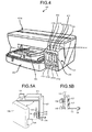
- Fig. 4 is a schematic diagram illustrating an outer appearance of an inkjet image forming apparatus 401.
- the image forming apparatus 401 includes an apparatus body 401a, a paper cassette 402 that is set to the apparatus body 401a and loads paper, and a discharge tray 403 that is set to the apparatus body 401a in a detachable manner and stocks paper on which an image has been recorded (formed).
- the image forming apparatus 401 includes a cartridge loader 404 on one end side of the front surface of the apparatus body 401a (next to the paper cassette 402).
- the cartridge loader 404 whose height is lower than that of the apparatus body 401a, protrudes from the front surface of the apparatus body 401a, loads therein ink cartridges, and has an operation/display unit 405 provided with operation buttons and displays on the upper surface thereof.
- a plurality of ink cartridges 410k, 410c, 410m, and 410y (simply referred to as an "ink cartridge 410" when colors are not specified) containing recording liquids (ink) having different colors can be loaded into the cartridge loader 404 by being inserted from the side surface side toward the rear side of the apparatus body 401a.
- the ink cartridges 410k, 410c, 410m, and 410y contain black (K) ink, cyan (C) ink, magenta (M) ink, and yellow (Y) ink, respectively, for example.
- the cartridge loader 404 is provided with a cartridge cover 406, which can be opened or closed when the ink cartridge is attached to or removed from the cartridge loader 404, on the front surface side thereof.
- remaining amount displays 411k, 411c, 411m, and 411y are arranged that display that a little amount of ink remains and no ink remains at arrangement positions corresponding to the respective attached positions (arrangement positions) of the ink cartridges 410k, 410c, 410m, and 410y.
- a power source button 412, a paper feed/print restart button 413, and a cancel button 414 are arranged on the operation/display unit 405.
- the power supplying unit according to the embodiment can be applied not only to the image forming apparatus but also to electronic apparatuses such as an MFP and a facsimile. According to the embodiment, it is possible to readily meet the installation environment of the electronic apparatus and satisfy safety standards required for the electronic apparatus.
Landscapes
- Physics & Mathematics (AREA)
- General Physics & Mathematics (AREA)
- Control Or Security For Electrophotography (AREA)
- Electrophotography Configuration And Component (AREA)
- Power Sources (AREA)
- Details Of Connecting Devices For Male And Female Coupling (AREA)
Applications Claiming Priority (1)
| Application Number | Priority Date | Filing Date | Title |
|---|---|---|---|
| JP2011194131A JP2013055011A (ja) | 2011-09-06 | 2011-09-06 | 電力供給ユニット、及び画像形成装置 |
Publications (2)
| Publication Number | Publication Date |
|---|---|
| EP2568352A2 true EP2568352A2 (de) | 2013-03-13 |
| EP2568352A3 EP2568352A3 (de) | 2013-04-24 |
Family
ID=47002629
Family Applications (1)
| Application Number | Title | Priority Date | Filing Date |
|---|---|---|---|
| EP12182899.0A Withdrawn EP2568352A3 (de) | 2011-09-06 | 2012-09-04 | Netzteil und Vorrichtung zur Bilderzeugung |
Country Status (2)
| Country | Link |
|---|---|
| EP (1) | EP2568352A3 (de) |
| JP (1) | JP2013055011A (de) |
Cited By (1)
| Publication number | Priority date | Publication date | Assignee | Title |
|---|---|---|---|---|
| CN114815542A (zh) * | 2021-01-27 | 2022-07-29 | 京瓷办公信息系统株式会社 | 图像形成装置 |
Families Citing this family (1)
| Publication number | Priority date | Publication date | Assignee | Title |
|---|---|---|---|---|
| JP7370905B2 (ja) * | 2020-03-10 | 2023-10-30 | キヤノン株式会社 | シート搬送装置及び画像形成装置 |
Citations (1)
| Publication number | Priority date | Publication date | Assignee | Title |
|---|---|---|---|---|
| JP2008512848A (ja) | 2005-08-30 | 2008-04-24 | フリボ ゲラーテバウ ゲーエムベーハー | 交換可能な電源プラグユニットを有するプラグイン電源 |
Family Cites Families (4)
| Publication number | Priority date | Publication date | Assignee | Title |
|---|---|---|---|---|
| US4259705A (en) * | 1979-03-27 | 1981-03-31 | Stifter Francis J | Combination surge suppressor filter |
| US5821636A (en) * | 1997-08-08 | 1998-10-13 | Compaq Computer Corp. | Low profile, redundant source power distribution unit |
| US6812971B2 (en) * | 2001-09-11 | 2004-11-02 | Olympus Optical Co., Ltd. | Electronic apparatus, stand and electronic apparatus stand system |
| GB2388971A (en) * | 2002-04-25 | 2003-11-26 | Kerio Technologies Inc | AC adaptor with replaceable resistive device |
-
2011
- 2011-09-06 JP JP2011194131A patent/JP2013055011A/ja not_active Withdrawn
-
2012
- 2012-09-04 EP EP12182899.0A patent/EP2568352A3/de not_active Withdrawn
Patent Citations (1)
| Publication number | Priority date | Publication date | Assignee | Title |
|---|---|---|---|---|
| JP2008512848A (ja) | 2005-08-30 | 2008-04-24 | フリボ ゲラーテバウ ゲーエムベーハー | 交換可能な電源プラグユニットを有するプラグイン電源 |
Cited By (1)
| Publication number | Priority date | Publication date | Assignee | Title |
|---|---|---|---|---|
| CN114815542A (zh) * | 2021-01-27 | 2022-07-29 | 京瓷办公信息系统株式会社 | 图像形成装置 |
Also Published As
| Publication number | Publication date |
|---|---|
| EP2568352A3 (de) | 2013-04-24 |
| JP2013055011A (ja) | 2013-03-21 |
Similar Documents
| Publication | Publication Date | Title |
|---|---|---|
| US10788775B2 (en) | Fixing device and image forming apparatus including same | |
| US8019241B2 (en) | Image forming apparatus | |
| US9188933B2 (en) | Power supply device and image forming apparatus | |
| EP2538282A2 (de) | Stromversorgungsmodul und Bilderzeugungsvorrichtung damit | |
| KR101335992B1 (ko) | 화상형성장치 | |
| US10955777B2 (en) | Fixing device including at least one temperature detector and a device-side connector and image forming apparatus including same | |
| JP2008304363A (ja) | ケーブル接続検知装置 | |
| JP7005335B2 (ja) | センサ制御装置 | |
| EP1925984B1 (de) | Bilderzeugungsvorrichtung und Leistungssteuerverfahren dafür | |
| EP2568352A2 (de) | Netzteil und Vorrichtung zur Bilderzeugung | |
| EP1626311B1 (de) | Zusätzliche Stromversorgung und Bildformungsapparat | |
| CN106662837B (zh) | 图像形成装置 | |
| US11106173B2 (en) | Image forming apparatus having mounting arrangement of first and second circuit boards | |
| JP2020030912A (ja) | コネクタ対接続状態検出装置、複合機及びコネクタ対接続状態検出方法 | |
| JP6145036B2 (ja) | 電子機器 | |
| JP6217583B2 (ja) | 画像形成装置 | |
| JP5941888B2 (ja) | 画像形成装置 | |
| JP2010078721A (ja) | 画像形成カートリッジ及び画像形成装置 | |
| JPH09160469A (ja) | 画像形成装置 | |
| JP2004085889A (ja) | 電装ユニット及び画像形成装置 | |
| US20250370397A1 (en) | Image forming apparatus | |
| JP2026005282A (ja) | 画像形成装置 | |
| JP2013024899A (ja) | 電子機器 | |
| JP2018054834A (ja) | 電源端子ユニットおよび画像形成装置 | |
| CN120652760A (zh) | 图像形成装置 |
Legal Events
| Date | Code | Title | Description |
|---|---|---|---|
| PUAI | Public reference made under article 153(3) epc to a published international application that has entered the european phase |
Free format text: ORIGINAL CODE: 0009012 |
|
| 17P | Request for examination filed |
Effective date: 20120904 |
|
| AK | Designated contracting states |
Kind code of ref document: A2 Designated state(s): AL AT BE BG CH CY CZ DE DK EE ES FI FR GB GR HR HU IE IS IT LI LT LU LV MC MK MT NL NO PL PT RO RS SE SI SK SM TR |
|
| AX | Request for extension of the european patent |
Extension state: BA ME |
|
| PUAL | Search report despatched |
Free format text: ORIGINAL CODE: 0009013 |
|
| AK | Designated contracting states |
Kind code of ref document: A3 Designated state(s): AL AT BE BG CH CY CZ DE DK EE ES FI FR GB GR HR HU IE IS IT LI LT LU LV MC MK MT NL NO PL PT RO RS SE SI SK SM TR |
|
| AX | Request for extension of the european patent |
Extension state: BA ME |
|
| RIC1 | Information provided on ipc code assigned before grant |
Ipc: H02M 7/00 20060101ALI20130321BHEP Ipc: G03G 15/00 20060101ALI20130321BHEP Ipc: H01R 31/06 20060101ALI20130321BHEP Ipc: G06F 1/26 20060101AFI20130321BHEP |
|
| STAA | Information on the status of an ep patent application or granted ep patent |
Free format text: STATUS: THE APPLICATION HAS BEEN WITHDRAWN |
|
| 18W | Application withdrawn |
Effective date: 20130506 |