EP2567918A2 - Verfahren und Vorrichtung zum Changieren eines Fadens auf einer Textilmaschine - Google Patents
Verfahren und Vorrichtung zum Changieren eines Fadens auf einer Textilmaschine Download PDFInfo
- Publication number
- EP2567918A2 EP2567918A2 EP12183041A EP12183041A EP2567918A2 EP 2567918 A2 EP2567918 A2 EP 2567918A2 EP 12183041 A EP12183041 A EP 12183041A EP 12183041 A EP12183041 A EP 12183041A EP 2567918 A2 EP2567918 A2 EP 2567918A2
- Authority
- EP
- European Patent Office
- Prior art keywords
- traversing rod
- traversing
- magnets
- rod
- motion
- Prior art date
- Legal status (The legal status is an assumption and is not a legal conclusion. Google has not performed a legal analysis and makes no representation as to the accuracy of the status listed.)
- Granted
Links
Images

Classifications
-
- B—PERFORMING OPERATIONS; TRANSPORTING
- B65—CONVEYING; PACKING; STORING; HANDLING THIN OR FILAMENTARY MATERIAL
- B65H—HANDLING THIN OR FILAMENTARY MATERIAL, e.g. SHEETS, WEBS, CABLES
- B65H54/00—Winding, coiling, or depositing filamentary material
- B65H54/02—Winding and traversing material on to reels, bobbins, tubes, or like package cores or formers
- B65H54/28—Traversing devices; Package-shaping arrangements
- B65H54/2818—Traversing devices driven by rod
-
- B—PERFORMING OPERATIONS; TRANSPORTING
- B65—CONVEYING; PACKING; STORING; HANDLING THIN OR FILAMENTARY MATERIAL
- B65H—HANDLING THIN OR FILAMENTARY MATERIAL, e.g. SHEETS, WEBS, CABLES
- B65H54/00—Winding, coiling, or depositing filamentary material
- B65H54/02—Winding and traversing material on to reels, bobbins, tubes, or like package cores or formers
- B65H54/28—Traversing devices; Package-shaping arrangements
- B65H54/2881—Traversing devices with a plurality of guides for winding on a plurality of bobbins
-
- B—PERFORMING OPERATIONS; TRANSPORTING
- B65—CONVEYING; PACKING; STORING; HANDLING THIN OR FILAMENTARY MATERIAL
- B65H—HANDLING THIN OR FILAMENTARY MATERIAL, e.g. SHEETS, WEBS, CABLES
- B65H54/00—Winding, coiling, or depositing filamentary material
- B65H54/02—Winding and traversing material on to reels, bobbins, tubes, or like package cores or formers
- B65H54/38—Arrangements for preventing ribbon winding ; Arrangements for preventing irregular edge forming, e.g. edge raising or yarn falling from the edge
- B65H54/385—Preventing edge raising, e.g. creeping arrangements
- B65H54/386—Preventing edge raising, e.g. creeping arrangements with energy storing means for recovering the kinetic energy at the end of the traversing stroke
-
- B—PERFORMING OPERATIONS; TRANSPORTING
- B65—CONVEYING; PACKING; STORING; HANDLING THIN OR FILAMENTARY MATERIAL
- B65H—HANDLING THIN OR FILAMENTARY MATERIAL, e.g. SHEETS, WEBS, CABLES
- B65H2701/00—Handled material; Storage means
- B65H2701/30—Handled filamentary material
- B65H2701/31—Textiles threads or artificial strands of filaments
Definitions
- the method for traversing of yarn upon its winding on bobbin mounted in winding mechanism of an operating unit of textile machine at which the traversing motion of yarn is generated through a straight-line reciprocating motion of traversing rod being common for a row of operating units, whereas before dead centre of the traversing rod its kinetic energy is transformed to potential energy, which contributes to deceleration in motion of the traversing rod, behind dead centre the potential energy of the traversing rod changes to kinetic energy, which contributes to acceleration in motion of the traversing rod.
- the device for traversing of yarn being wound on winding bobbin mounted in winding mechanism of an operating unit of textile machine comprising along the machine arranged traversing rod being common for a row of operating units of one side of the machine coupled with a drive imparting it a straight-line reciprocating motion of a variable stroke and at least two magnetic couples formed of opposite poles of magnets arranged one against another on machine frame and on the traversing rod.
- Winding of cylindric or taper cross-wound bobbins on textile machines with a row of side by side arranged operating units, for example on open-end spinning machines, winding machines or two-for-one twisters is commonly performed by means of a continuous traversing rod passing along one side of operating units of the machine.
- the bobbins being wound during winding roll by their surface being wound on cylindrical surface of the driving roller, while their rotation axis is parallel with axis of the traversing rod and the traversing rod upon winding of the bobbin performs a straight-line reciprocating motion. Stroke of the traversing rod corresponds to length of surface line of package of the bobbin being wound.
- the speed of the yarn being delivered to the bobbin being wound is high, which requires also a high frequency of straight-line reciprocating motion of the traversing rod.
- the traversing rod has e.g. a length of 30 metres, thus having a considerable weight.
- Driving mechanism of the traversing rod is usually coupled with one of its ends.
- a long traversing rod is thus sensitive to formation of vibrations.
- longitudinal waves of deformation are expanded, but also the traverse waves caused by that the rod is subject to buckling upon existence of play in guide bearings.
- yawing results in increasing of friction forces.
- the traverse waves on the rod have a lower speed than the longitudinal waves and oscillation of the rod is usually very complicated. Motion of a free end of traversing rod after then differs from motion of rod section in the place of its connection with the driving mechanism.
- the device according to CZ 1997-2323 A3 derives the motion of the traversing rod through a cam mechanism.
- the springs which absorb its dynamic forces and they speed it up retroactively.
- Position of the springs with respect to the machine frame is a constant one, or it can be displaced according to displacement of the outer dead centres of the traversing rod upon overlapping of edges on the bobbin.
- Solution according to CZ 300588 B6 proposes to connect to the traversing rod rotationally the end of a drawbar, whose second end is rotationally connected with rotationally mounted main crank.
- This crank creates an output means of rotational electronically controlled drive coupled with the driving mechanism.
- the main crank together with electronically controlled drive is connected with frame of textile machine through a displaceable coupling to ensure overlapping of yarn package in dead centres, so called blurring.
- Angular speed of the main crank is continuously decreased or increased by means of rotational electronically controlled drive controlled with controlling mechanism upon motion of traversing element from one dead centre to the second dead centre. This happens in linear relation on the required magnitude of angle of yarn crossing on the bobbin being wound and/or in linear relation on position of the traversing element, through which the required angle of yarn crossing on the bobbin being wound and/or the required course for speed of motion of the traversing element is achieved.
- Function of such a device may satisfactorily meet requirements for a quality arrangement of package, at the same time it may also contribute to solving problems of inertia forces generated by a reciprocating motion of the traversing rod.
- Shortcoming of such control means is their complexity thus also the price, at the same time such complexity brings increase of failure rate.
- CZ 2007-214 A3 utilises two couples of magnets, out of which always one is mounted adjustably on machine frame, the second in a fixed manner on the traversing rod, while they are mutually adjacent with the same poles.
- This solution brings an efficient damping of straight-line reciprocating motion of the traversing rod in area of dead centres, while energy of inertia mass of the rod in time before the dead centre is accumulated and then this energy is consumed which contributes to starting run of the traversing rod behind dead centre.
- the goal of the invention is to remove or at least substantially reduce shortcomings of the background art and to bring good possibilities when setting position of dead centres of the traversing rod, at the same time to achieve a high level of accumulation of energy of the traversing rod being stopped and its backward expenditure.
- the goal of invention has been achieved by a method for traversing of yarn upon its winding on bobbin mounted in winding mechanism of an operating unit of textile machine, whose principle consists in that, before dead centre of the traversing rod in the first phase of its deceleration its kinetic energy transforms to potential energy of magnetic field, and in the second phase of deceleration to potential energy of a field of elastic forces, subsequently behind dead centre of the traversing rod in the first phase of acceleration of the traversing rod the potential energy of the field of elastic forces transforms to kinetic energy of the traversing rod, and in the second phase of its acceleration the potential energy of magnetic field transforms to its kinetic energy.
- the advantages of the invention are in that it is without beats.
- the advantage is a flat characteristics in the second phase of deceleration, which secures a minimum change in force during the blurring cycle, this without necessity of an additional controlled motion of stationary magnet towards the machine frame as it is in CZ-2007-214 A3 .
- the device for yarn traversing being wound on winding bobbin mounted in winding mechanism of an operating unit of textile machine, whose principle consists in that, the magnetic couples are formed of at least one moving magnet mounted on the traversing rod and two stationary magnets, which are on the machine frame mounted by means of at least one elastically deformable means in a prestressed status, while the prestress of elastically deformable means is lower than mutual detachment force of magnetic couple at mutual contact of their identical poles.
- the device comprises two stationary magnets, out of which each is coupled with one independent elastically deformable means.
- Each of stationary magnets is mounted in an independent bushing, while between it and bottom of the bushing there is inserted elastically deformable means, preferably a compression spiral spring.
- the device is relatively cheap, easily adjustable.
- the device comprises two stationary magnets coupled with one common elastically deformable means.
- the magnets are mounted displaceably in cavity of a common bushing in a fixed manner connected with machine frame and arranged axially with the traversing rod, while the elastically deformable means is arranged between the stationary magnets, while the moving magnets are attached to the traversing rod outside the bushing so that the bushing is to be found between the moving magnets, at the same time the difference in distance of mutually adjacent faces of moving magnets and the distance of mutually averted faces of stationary magnets in a prestressed status of an elastically deformable means equals to a basic stroke of the traversing rod which is lower than a real stroke of the traversing rod.
- each stationary magnet is mounted displaceably in cavity of one of two independent bushings in a fixed manner connected with machine frame and arranged axially with the traversing rod, while the elastically deformable means is always arranged between the bushing bottom and a stationary magnet, while the moving magnets or moving magnet is attached on the traversing rod in area between the bushings, at the same time the difference in distance of mutually adjacent faces of stationary magnets in a prestressed status of an elastically deformable means and the distance of mutually averted faces of moving magnets or faces of moving magnet equals to a basic stroke of the traversing rod which is lower than a real stroke of the traversing rod.
- the moving magnets on the traversing rod are attached so that they can be re-adjusted. This enables to modify length of packages.
- the magnets themselves, it is advantageous if the magnets are arranged symmetrically to the longitudinal axis of the traversing rod which enables to create them as rings, with whose face side the mating surfaces of elastically deformable means are in contact.
- Elastically deformable means is formed of a spring, preferably of a compression spiral spring. This is an affordable part, it can be easily adjusted and may be produced in narrow production tolerances from the point of view of their force characteristics.
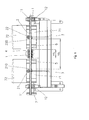
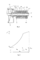
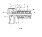
- Exemplary embodiments of the device according to the invention are schematically represented in a drawing, where shows Fig. 1 a view to a part of means of a couple of mutually neighbouring operating units of textile machine in embodiment with one spring, Fig. 2 a detail of mutual position of traversing rod with guide of yarn being wound, magnets and spring in area of dead centre of the reciprocating motion of the traversing rod, Fig. 3 dependence of a course of detachment force of magnets and force of compression spring before attaining the dead centre of reciprocating motion of traversing rod, Fig. 4 . view to a section of means of a couple of mutually neighbouring operating units of textile machine in embodiment with two springs and Fig. 5 detail of mutual position of traversing rod with guide of yarn being wound, magnets and spring in area of dead centre of reciprocating motion of the traversing rod for embodiment with two springs.
- Fig. 1 Exemplary embodiment of the device according to the invention is represented in Fig. 1 , on which there are two neighbouring operating units of a spinning frame.
- frame 1 of the machine along a row of operating units arranged in sections having a certain number of places there is arranged a continuous traversing rod 2 mounted slidably in the slide-way 11 and connected to a known not represented driving mechanism, through which it is brought into a controlled straight-line reciprocating motion and through which the position of dead centres of the traversing rod 2 is controlled.
- traverse guide 21 of yarn for operating unit represented on the LH side
- 22 for operating unit represented on the RH side
- a cylindrical bushing 4 is attached, in detail represented in the Fig. 2 .
- the continuous traversing rod 2 thus passes through the bushing 4 .
- Two cylindrical guidance 43 are slidably mounted in inner cylindric cavity of the bushing 4 between its collars 41, 42 , in whose cavity the compression spiral spring 44 is mounted.
- the collar 42 to the body of bushing 4 is attached in a dismountable manner e.g. by means of a screw 45. This enables to insert the guidance 43 and the spring 44 into a body of the bushing 4.
- the elastically deformable means need not to be only the compression spiral spring 44. It can be of course superseded by another elastically deformable means, e.g. other type of metal spring, possibly a pneumatic spring.
- Mutual arrangement of magnets 5, 210, and 6, 220 is such that the difference of distance vp 1 of mutually adjacent faces of moving magnets 210, 220 and distance vo 1 of mutually averted faces of stationary magnets 5, 6 is a length of basic stroke of the traversing rod 2, at which the spring 44 is permanently constantly prestressed without compression in area of dead centres of the traversing rod 2.
- the real stroke of the traversing rod 2 is greater than the basic stroke.
- the difference of the real stroke and of basic stroke equals to the maximum on machine adjustable stroke of blurring of edges in package. Upon motion of the traversing rod this difference in lengths causes compression of the spring 44 in dead centres of motion of the traversing rod. Compression rate of the spring 44 is variable and corresponds to actual dead centre during the blurring cycle.
- the moving magnets 210, 220 with respect to the traversing rod 2 may be attached displaceably. This is at a greater number of units according to the invention arranged along one traversing rod 2 less advantageous from the point of view of machine adjustment, but it enables to change the length of basic stroke of the traversing rod 2 at the same time preserving a size and course of detachment forces before dead centres of the traversing rod 2.
- a continuous driving shaft 7 of winding mechanism mounted rotatably in bearings 12 and connected to a known not represented drive.
- a driving roller 71 is attached, with whose friction circumference a surface of the bobbin 72 being wound is in contact during yarn 3 winding.
- the bobbin 72 being wound has a cylindrical shape, its rotation axis is parallel with rotation axis of the driving shaft 7.
- the shown exemplary embodiment does not specify number of bushings for a whole one side of the spinning machine.
- Bushing 4 with stationary magnets 5, 6 and to it corresponding couple of moving magnets 210, 220 need not to be arranged in each section of operating units, or vice versa there can be a greater number of them than it corresponds to number of sections.
- a space may be utilised, that is usually available between the neighbouring sections of the machine. This enables an additional installation of the device according to the invention on spinning machines being already in operation. It is obvious that in cases when a greater number of bushings 4 positioned on one traversing rod 2 is utilised, some bushing 4 may be positioned at the end of the traversing rod 2.
- Fig. 3 represents dependence of a course of detachment force F of magnets 5 and 210 , and a force of compression spring 44 on position x of traversing rod 2 in area of dead centre of its straight-line reciprocating motion.
- This position is given by setting of regulation mechanism which in a known manner controls a change in position of dead centres of the traversing rod 2 upon winding the yarn 3, through which overlapping of package in dead centres i.e. blurring is achieved.
- the spring 44 In idle mode of the device the spring 44 is mounted in bushing 4 with prestress F 1 .
- the spring 44 has a flat linear characteristics, the magnets 5, 210 do not practically approach mutually, but owing to the weak spring 44 in the second phase of motion of the traversing rod 2 on the LH side situated guidance 43 upon compression of the spring 44 is being displaced with respect to the body of of the bushing 4 to the right.
- Detachment force increases on the track d 12 , from the value F 1 in position x 1 to value F 2 in position x 2 in linear manner and gradually.
- the distance d m between magnets at prestress F 1 is given by equilibrium of forces between the magnet and magnet with spring. During compression of the spring the force increases only at minimum and so the resultant gap between magnets d m also decreases slightly, it does not change practically.
- Fig. 4 and the detailed Fig. 5 represent alternative embodiment of the device according to the invention, which comprises two bushings 8 attached to frame 1 of the machine axially with the traversing rod 2 and mutually in a mirror view to the left and to the right in neighbourhood of the traverse guide 21 of yarn of the operating unit represented on the LH side.
- the bushings 8 on mutually averted sides have the fixed faces 81 and on mutually adjacent sides they have collars 82.
- the cylindrical guidance 83 In bushings 8 from the side of collar 82 always is slidably mounted the cylindrical guidance 83, in whose cavity the compression spiral spring 84 is mounted, whose second side leans against the fixed face 81 of the bushing 8.
- the collar 82 to body of the bushing 8 is attached in a dismountable manner e.g.
- a longer ring moving magnet 200 represented schematically under axis of the traversing rod 2.
- a longer ring moving magnet 200 represented schematically under axis of the traversing rod 2.
- two ring moving magnets 210, 220 are attached to the traversing rod 2 in area of traverse guide 21 in exemplary embodiment.
- the moving magnet 200, or moving magnets 210, 220 to the respective stationary magnets 5, 6 are adjacent by the identical poles, through which practically create cooperating couples of mutually repelling magnets, similarly as it is at embodiment represented in Fig. 1 .
- Mutual arrangement of magnets 5, 6, 200 (possibly 210, 220 ) is such, that the difference in distance vp 2 of mutually adjacent faces of stationary magnets 5, 6 and distance vo 2 of averted faces of moving magnet 220 (possibly of mutually averted faces of moving magnets 210, 220) represents length of basic stroke of the traversing rod 2, at which the springs 84 are permanently constantly prestressed without compression in area of dead centres of the traversing rod 2.
- the real stroke of the traversing rod 2 is greater than the basic stroke.
- the difference of the real stroke and of basic stroke equals to the maximum on machine adjustable stroke of blurring of edges in package. Upon motion of the traversing rod this difference in lengths causes compression of the spring 84 in dead centres of motion of the traversing rod.
- Compression rate of the spring 84 is variable and corresponds to actual dead centre during the blurring cycle.
- the moving magnets 210, 220 with respect to the traversing rod 2 may be attached displaceably analogically with the above mentioned embodiment from Fig. 1 .
- the size and course of detachment forces of magnets 5, 210 in combination with flat characteristics of the spring 44, 84 enable to achieve a high degree of energy accumulation on a short track d 02 before the dead centre of the traversing rod 2, with a low difference of final forces F 1 , F 2 at variable track d 02 in stroke of the traversing rod 2.
- Positioning of accumulators along a whole traversing rod enables to eliminate impact of longitudinal oscillation of the traversing rod, thus enables to achieve highly accurate positions in dead centres of guides attached to the traversing rod 2 and an ideal blurring, thus the quality of package being formed.
- the device according to the invention is simple in its structure. This fact enables to install them on more places along the traversing rod 2.
- the exemplary embodiments are cited with the goal to explain perfectly method and device according to the invention, at the same time their meaning is not a limiting one.
Landscapes
- Chemical & Material Sciences (AREA)
- Chemical Kinetics & Catalysis (AREA)
- Engineering & Computer Science (AREA)
- Textile Engineering (AREA)
- Spinning Or Twisting Of Yarns (AREA)
- Winding Filamentary Materials (AREA)
Applications Claiming Priority (1)
| Application Number | Priority Date | Filing Date | Title |
|---|---|---|---|
| CZ20110553A CZ303167B6 (cs) | 2011-09-06 | 2011-09-06 | Zpusob a zarízení k rozvádení príze na textilních strojích |
Publications (3)
| Publication Number | Publication Date |
|---|---|
| EP2567918A2 true EP2567918A2 (de) | 2013-03-13 |
| EP2567918A3 EP2567918A3 (de) | 2013-11-13 |
| EP2567918B1 EP2567918B1 (de) | 2018-01-31 |
Family
ID=46021929
Family Applications (1)
| Application Number | Title | Priority Date | Filing Date |
|---|---|---|---|
| EP12183041.8A Not-in-force EP2567918B1 (de) | 2011-09-06 | 2012-09-05 | Verfahren und Vorrichtung zum Changieren eines Fadens auf einer Textilmaschine |
Country Status (2)
| Country | Link |
|---|---|
| EP (1) | EP2567918B1 (de) |
| CZ (1) | CZ303167B6 (de) |
Cited By (3)
| Publication number | Priority date | Publication date | Assignee | Title |
|---|---|---|---|---|
| CN103586308A (zh) * | 2013-11-13 | 2014-02-19 | 贵州钢绳股份有限公司 | 一种热处理收线防缠绕的装置 |
| CZ304685B6 (cs) * | 2013-12-18 | 2014-08-27 | Technická univerzita v Liberci | Způsob rozvádění příze při jejím navíjení na cívku uloženou v navíjecím ústrojí pracovního místa textilního stroje a zařízení k jeho provádění |
| CN108217321A (zh) * | 2018-03-05 | 2018-06-29 | 广东理工学院 | 弹射式导线咀总承及导线咀系统 |
Citations (3)
| Publication number | Priority date | Publication date | Assignee | Title |
|---|---|---|---|---|
| CZ232397A3 (cs) | 1997-07-21 | 1999-02-17 | Václav Ing. Šafář | Zařízení pro navíjení příze na bezvřetenových dopřádacích strojích |
| CZ2007214A3 (cs) | 2007-03-22 | 2008-10-01 | Rieter Cz A.S. | Zarízení k rozvádení príze na textilních strojích |
| CZ300588B6 (cs) | 2006-05-22 | 2009-06-24 | Technická univerzita v Liberci | Zpusob rozvádení príze pri navíjení príze na cívku a zarízení k provádení tohoto zpusobu |
Family Cites Families (8)
| Publication number | Priority date | Publication date | Assignee | Title |
|---|---|---|---|---|
| WO1999031000A1 (de) * | 1997-12-17 | 1999-06-24 | Barmag Ag | Changiereinrichtung zum verlegen eines fadens |
| DE29909105U1 (de) * | 1999-05-25 | 1999-07-22 | Textilma Ag, Hergiswil | Fadenfördervorrichtung |
| DE10133604A1 (de) * | 2001-07-13 | 2003-02-06 | Zinser Textilmaschinen Gmbh | Verfahren und Vorrichtung zum Hin- und Herbewegen von Luntenführern |
| CN2591002Y (zh) * | 2002-12-04 | 2003-12-10 | 陆峻峰 | 槽筒式络筒机断纱自停及定长装置 |
| DE10332399A1 (de) * | 2003-07-17 | 2005-02-03 | Saurer Gmbh & Co. Kg | Energiespeicher für einen Fingerfadenführer einer Kreuzspulen herstellenden Textilmaschine |
| CZ294639B6 (cs) * | 2003-12-02 | 2005-02-16 | Jindřich Strmiska | Způsob navíjení kuželového křížem soukaného návinu cívky zejména na bezvřetenovém dopřádacím stroji nebo skacím stroji a zařízení k provádění tohoto způsobu |
| DE102006053135A1 (de) * | 2006-11-11 | 2008-05-15 | Oerlikon Textile Gmbh & Co. Kg | Fadenchangiervorrichtung für eine Kreuzspulen herstellende Textilmaschine |
| DE102008000601A1 (de) * | 2007-03-22 | 2008-09-25 | Rieter Cz A.S. | Garnchangiereinrichtung auf den Textilmaschinen |
-
2011
- 2011-09-06 CZ CZ20110553A patent/CZ303167B6/cs not_active IP Right Cessation
-
2012
- 2012-09-05 EP EP12183041.8A patent/EP2567918B1/de not_active Not-in-force
Patent Citations (3)
| Publication number | Priority date | Publication date | Assignee | Title |
|---|---|---|---|---|
| CZ232397A3 (cs) | 1997-07-21 | 1999-02-17 | Václav Ing. Šafář | Zařízení pro navíjení příze na bezvřetenových dopřádacích strojích |
| CZ300588B6 (cs) | 2006-05-22 | 2009-06-24 | Technická univerzita v Liberci | Zpusob rozvádení príze pri navíjení príze na cívku a zarízení k provádení tohoto zpusobu |
| CZ2007214A3 (cs) | 2007-03-22 | 2008-10-01 | Rieter Cz A.S. | Zarízení k rozvádení príze na textilních strojích |
Cited By (3)
| Publication number | Priority date | Publication date | Assignee | Title |
|---|---|---|---|---|
| CN103586308A (zh) * | 2013-11-13 | 2014-02-19 | 贵州钢绳股份有限公司 | 一种热处理收线防缠绕的装置 |
| CZ304685B6 (cs) * | 2013-12-18 | 2014-08-27 | Technická univerzita v Liberci | Způsob rozvádění příze při jejím navíjení na cívku uloženou v navíjecím ústrojí pracovního místa textilního stroje a zařízení k jeho provádění |
| CN108217321A (zh) * | 2018-03-05 | 2018-06-29 | 广东理工学院 | 弹射式导线咀总承及导线咀系统 |
Also Published As
| Publication number | Publication date |
|---|---|
| CZ2011553A3 (cs) | 2012-05-09 |
| CZ303167B6 (cs) | 2012-05-09 |
| EP2567918B1 (de) | 2018-01-31 |
| EP2567918A3 (de) | 2013-11-13 |
Similar Documents
| Publication | Publication Date | Title |
|---|---|---|
| EP2765102B1 (de) | Verfahren zur Verteilung von aufgewickeltem Garn und Vorrichtung zur Durchführung des Verfahrens | |
| EP2567918B1 (de) | Verfahren und Vorrichtung zum Changieren eines Fadens auf einer Textilmaschine | |
| US6904745B2 (en) | Thread-guiding device for open-end spinning frames | |
| CN103541074A (zh) | 纺纱机伺服驱动卷绕横动装置 | |
| CN101580983A (zh) | 倍捻机的智能防叠松边装置及其方法 | |
| CN101104487A (zh) | 用于制造具有调整横动程的筒管的高频丝线导向装置 | |
| CN203112232U (zh) | 用于使纺织机器上的纱线往复的设备 | |
| EP2432722A1 (de) | Changiereinrichtung | |
| US6053449A (en) | Yarn winding apparatus with spindle support | |
| CN101318599B (zh) | 纺织机上用于纱线往复运动的装置 | |
| CN201592928U (zh) | 自动络筒机的张力控制装置 | |
| CN104724543B (zh) | 用于使纱在其卷绕在线筒上期间横动的方法和装置 | |
| EP1498378B1 (de) | Energiespeicher für einen Fingerfadenführer einer Kreuzspulen herstellenden Textilmaschine | |
| EP2562112B1 (de) | Vorrichtung zum Traversieren von auf einer Spule aufgewickeltem Garn | |
| EP0925391A1 (de) | Topfspinnvorrichtung | |
| CN201089670Y (zh) | 卷绕张力控制装置 | |
| CN102837991A (zh) | 指形导纱器 | |
| CN101535159A (zh) | 制造交叉卷绕筒的纺织机用的纱线横动装置 | |
| WO2017101892A1 (en) | Method and a device for winding yarn on a bobbin on yarn manufacturing textile machines | |
| CN101100770A (zh) | 倍捻机的智能防叠松边装置 | |
| DE102008000601A1 (de) | Garnchangiereinrichtung auf den Textilmaschinen | |
| CN108238494B (zh) | 纱筒成型横动驱动装置 | |
| CZ22834U1 (cs) | Zařízení k rozvádění příze na textilních strojích | |
| US3352505A (en) | Textile apparatus | |
| CN203048308U (zh) | 收卷机 |
Legal Events
| Date | Code | Title | Description |
|---|---|---|---|
| PUAI | Public reference made under article 153(3) epc to a published international application that has entered the european phase |
Free format text: ORIGINAL CODE: 0009012 |
|
| AK | Designated contracting states |
Kind code of ref document: A2 Designated state(s): AL AT BE BG CH CY CZ DE DK EE ES FI FR GB GR HR HU IE IS IT LI LT LU LV MC MK MT NL NO PL PT RO RS SE SI SK SM TR |
|
| AX | Request for extension of the european patent |
Extension state: BA ME |
|
| PUAL | Search report despatched |
Free format text: ORIGINAL CODE: 0009013 |
|
| AK | Designated contracting states |
Kind code of ref document: A3 Designated state(s): AL AT BE BG CH CY CZ DE DK EE ES FI FR GB GR HR HU IE IS IT LI LT LU LV MC MK MT NL NO PL PT RO RS SE SI SK SM TR |
|
| AX | Request for extension of the european patent |
Extension state: BA ME |
|
| RIC1 | Information provided on ipc code assigned before grant |
Ipc: B65H 54/28 20060101AFI20131010BHEP Ipc: B65H 54/38 20060101ALI20131010BHEP |
|
| 17P | Request for examination filed |
Effective date: 20140428 |
|
| RBV | Designated contracting states (corrected) |
Designated state(s): AL AT BE BG CH CY CZ DE DK EE ES FI FR GB GR HR HU IE IS IT LI LT LU LV MC MK MT NL NO PL PT RO RS SE SI SK SM TR |
|
| 17Q | First examination report despatched |
Effective date: 20150810 |
|
| STAA | Information on the status of an ep patent application or granted ep patent |
Free format text: STATUS: EXAMINATION IS IN PROGRESS |
|
| GRAP | Despatch of communication of intention to grant a patent |
Free format text: ORIGINAL CODE: EPIDOSNIGR1 |
|
| STAA | Information on the status of an ep patent application or granted ep patent |
Free format text: STATUS: GRANT OF PATENT IS INTENDED |
|
| INTG | Intention to grant announced |
Effective date: 20170822 |
|
| RIN1 | Information on inventor provided before grant (corrected) |
Inventor name: VALTERA, JAN Inventor name: BERAN, JAROSLAV |
|
| GRAS | Grant fee paid |
Free format text: ORIGINAL CODE: EPIDOSNIGR3 |
|
| GRAA | (expected) grant |
Free format text: ORIGINAL CODE: 0009210 |
|
| STAA | Information on the status of an ep patent application or granted ep patent |
Free format text: STATUS: THE PATENT HAS BEEN GRANTED |
|
| AK | Designated contracting states |
Kind code of ref document: B1 Designated state(s): AL AT BE BG CH CY CZ DE DK EE ES FI FR GB GR HR HU IE IS IT LI LT LU LV MC MK MT NL NO PL PT RO RS SE SI SK SM TR |
|
| REG | Reference to a national code |
Ref country code: GB Ref legal event code: FG4D Ref country code: CH Ref legal event code: EP |
|
| REG | Reference to a national code |
Ref country code: AT Ref legal event code: REF Ref document number: 967164 Country of ref document: AT Kind code of ref document: T Effective date: 20180215 |
|
| REG | Reference to a national code |
Ref country code: IE Ref legal event code: FG4D |
|
| REG | Reference to a national code |
Ref country code: DE Ref legal event code: R096 Ref document number: 602012042524 Country of ref document: DE |
|
| REG | Reference to a national code |
Ref country code: NL Ref legal event code: MP Effective date: 20180131 |
|
| REG | Reference to a national code |
Ref country code: LT Ref legal event code: MG4D |
|
| REG | Reference to a national code |
Ref country code: AT Ref legal event code: MK05 Ref document number: 967164 Country of ref document: AT Kind code of ref document: T Effective date: 20180131 |
|
| PG25 | Lapsed in a contracting state [announced via postgrant information from national office to epo] |
Ref country code: LT Free format text: LAPSE BECAUSE OF FAILURE TO SUBMIT A TRANSLATION OF THE DESCRIPTION OR TO PAY THE FEE WITHIN THE PRESCRIBED TIME-LIMIT Effective date: 20180131 Ref country code: NL Free format text: LAPSE BECAUSE OF FAILURE TO SUBMIT A TRANSLATION OF THE DESCRIPTION OR TO PAY THE FEE WITHIN THE PRESCRIBED TIME-LIMIT Effective date: 20180131 Ref country code: FI Free format text: LAPSE BECAUSE OF FAILURE TO SUBMIT A TRANSLATION OF THE DESCRIPTION OR TO PAY THE FEE WITHIN THE PRESCRIBED TIME-LIMIT Effective date: 20180131 Ref country code: NO Free format text: LAPSE BECAUSE OF FAILURE TO SUBMIT A TRANSLATION OF THE DESCRIPTION OR TO PAY THE FEE WITHIN THE PRESCRIBED TIME-LIMIT Effective date: 20180430 Ref country code: ES Free format text: LAPSE BECAUSE OF FAILURE TO SUBMIT A TRANSLATION OF THE DESCRIPTION OR TO PAY THE FEE WITHIN THE PRESCRIBED TIME-LIMIT Effective date: 20180131 Ref country code: HR Free format text: LAPSE BECAUSE OF FAILURE TO SUBMIT A TRANSLATION OF THE DESCRIPTION OR TO PAY THE FEE WITHIN THE PRESCRIBED TIME-LIMIT Effective date: 20180131 |
|
| PG25 | Lapsed in a contracting state [announced via postgrant information from national office to epo] |
Ref country code: RS Free format text: LAPSE BECAUSE OF FAILURE TO SUBMIT A TRANSLATION OF THE DESCRIPTION OR TO PAY THE FEE WITHIN THE PRESCRIBED TIME-LIMIT Effective date: 20180131 Ref country code: GR Free format text: LAPSE BECAUSE OF FAILURE TO SUBMIT A TRANSLATION OF THE DESCRIPTION OR TO PAY THE FEE WITHIN THE PRESCRIBED TIME-LIMIT Effective date: 20180501 Ref country code: SE Free format text: LAPSE BECAUSE OF FAILURE TO SUBMIT A TRANSLATION OF THE DESCRIPTION OR TO PAY THE FEE WITHIN THE PRESCRIBED TIME-LIMIT Effective date: 20180131 Ref country code: AT Free format text: LAPSE BECAUSE OF FAILURE TO SUBMIT A TRANSLATION OF THE DESCRIPTION OR TO PAY THE FEE WITHIN THE PRESCRIBED TIME-LIMIT Effective date: 20180131 Ref country code: IS Free format text: LAPSE BECAUSE OF FAILURE TO SUBMIT A TRANSLATION OF THE DESCRIPTION OR TO PAY THE FEE WITHIN THE PRESCRIBED TIME-LIMIT Effective date: 20180531 Ref country code: LV Free format text: LAPSE BECAUSE OF FAILURE TO SUBMIT A TRANSLATION OF THE DESCRIPTION OR TO PAY THE FEE WITHIN THE PRESCRIBED TIME-LIMIT Effective date: 20180131 Ref country code: BG Free format text: LAPSE BECAUSE OF FAILURE TO SUBMIT A TRANSLATION OF THE DESCRIPTION OR TO PAY THE FEE WITHIN THE PRESCRIBED TIME-LIMIT Effective date: 20180430 Ref country code: PL Free format text: LAPSE BECAUSE OF FAILURE TO SUBMIT A TRANSLATION OF THE DESCRIPTION OR TO PAY THE FEE WITHIN THE PRESCRIBED TIME-LIMIT Effective date: 20180131 |
|
| PG25 | Lapsed in a contracting state [announced via postgrant information from national office to epo] |
Ref country code: AL Free format text: LAPSE BECAUSE OF FAILURE TO SUBMIT A TRANSLATION OF THE DESCRIPTION OR TO PAY THE FEE WITHIN THE PRESCRIBED TIME-LIMIT Effective date: 20180131 Ref country code: RO Free format text: LAPSE BECAUSE OF FAILURE TO SUBMIT A TRANSLATION OF THE DESCRIPTION OR TO PAY THE FEE WITHIN THE PRESCRIBED TIME-LIMIT Effective date: 20180131 Ref country code: IT Free format text: LAPSE BECAUSE OF FAILURE TO SUBMIT A TRANSLATION OF THE DESCRIPTION OR TO PAY THE FEE WITHIN THE PRESCRIBED TIME-LIMIT Effective date: 20180131 Ref country code: EE Free format text: LAPSE BECAUSE OF FAILURE TO SUBMIT A TRANSLATION OF THE DESCRIPTION OR TO PAY THE FEE WITHIN THE PRESCRIBED TIME-LIMIT Effective date: 20180131 |
|
| REG | Reference to a national code |
Ref country code: DE Ref legal event code: R097 Ref document number: 602012042524 Country of ref document: DE |
|
| PG25 | Lapsed in a contracting state [announced via postgrant information from national office to epo] |
Ref country code: SK Free format text: LAPSE BECAUSE OF FAILURE TO SUBMIT A TRANSLATION OF THE DESCRIPTION OR TO PAY THE FEE WITHIN THE PRESCRIBED TIME-LIMIT Effective date: 20180131 Ref country code: SM Free format text: LAPSE BECAUSE OF FAILURE TO SUBMIT A TRANSLATION OF THE DESCRIPTION OR TO PAY THE FEE WITHIN THE PRESCRIBED TIME-LIMIT Effective date: 20180131 Ref country code: DK Free format text: LAPSE BECAUSE OF FAILURE TO SUBMIT A TRANSLATION OF THE DESCRIPTION OR TO PAY THE FEE WITHIN THE PRESCRIBED TIME-LIMIT Effective date: 20180131 Ref country code: CZ Free format text: LAPSE BECAUSE OF FAILURE TO SUBMIT A TRANSLATION OF THE DESCRIPTION OR TO PAY THE FEE WITHIN THE PRESCRIBED TIME-LIMIT Effective date: 20180131 |
|
| PLBE | No opposition filed within time limit |
Free format text: ORIGINAL CODE: 0009261 |
|
| STAA | Information on the status of an ep patent application or granted ep patent |
Free format text: STATUS: NO OPPOSITION FILED WITHIN TIME LIMIT |
|
| 26N | No opposition filed |
Effective date: 20181102 |
|
| PG25 | Lapsed in a contracting state [announced via postgrant information from national office to epo] |
Ref country code: SI Free format text: LAPSE BECAUSE OF FAILURE TO SUBMIT A TRANSLATION OF THE DESCRIPTION OR TO PAY THE FEE WITHIN THE PRESCRIBED TIME-LIMIT Effective date: 20180131 |
|
| REG | Reference to a national code |
Ref country code: DE Ref legal event code: R119 Ref document number: 602012042524 Country of ref document: DE |
|
| PG25 | Lapsed in a contracting state [announced via postgrant information from national office to epo] |
Ref country code: MC Free format text: LAPSE BECAUSE OF FAILURE TO SUBMIT A TRANSLATION OF THE DESCRIPTION OR TO PAY THE FEE WITHIN THE PRESCRIBED TIME-LIMIT Effective date: 20180131 |
|
| REG | Reference to a national code |
Ref country code: CH Ref legal event code: PL |
|
| GBPC | Gb: european patent ceased through non-payment of renewal fee |
Effective date: 20180905 |
|
| REG | Reference to a national code |
Ref country code: BE Ref legal event code: MM Effective date: 20180930 |
|
| REG | Reference to a national code |
Ref country code: IE Ref legal event code: MM4A |
|
| PG25 | Lapsed in a contracting state [announced via postgrant information from national office to epo] |
Ref country code: LU Free format text: LAPSE BECAUSE OF NON-PAYMENT OF DUE FEES Effective date: 20180905 |
|
| PG25 | Lapsed in a contracting state [announced via postgrant information from national office to epo] |
Ref country code: DE Free format text: LAPSE BECAUSE OF NON-PAYMENT OF DUE FEES Effective date: 20190402 Ref country code: IE Free format text: LAPSE BECAUSE OF NON-PAYMENT OF DUE FEES Effective date: 20180905 |
|
| PG25 | Lapsed in a contracting state [announced via postgrant information from national office to epo] |
Ref country code: LI Free format text: LAPSE BECAUSE OF NON-PAYMENT OF DUE FEES Effective date: 20180930 Ref country code: CH Free format text: LAPSE BECAUSE OF NON-PAYMENT OF DUE FEES Effective date: 20180930 Ref country code: FR Free format text: LAPSE BECAUSE OF NON-PAYMENT OF DUE FEES Effective date: 20180930 Ref country code: BE Free format text: LAPSE BECAUSE OF NON-PAYMENT OF DUE FEES Effective date: 20180930 |
|
| PG25 | Lapsed in a contracting state [announced via postgrant information from national office to epo] |
Ref country code: GB Free format text: LAPSE BECAUSE OF NON-PAYMENT OF DUE FEES Effective date: 20180905 |
|
| PG25 | Lapsed in a contracting state [announced via postgrant information from national office to epo] |
Ref country code: MT Free format text: LAPSE BECAUSE OF NON-PAYMENT OF DUE FEES Effective date: 20180905 |
|
| PG25 | Lapsed in a contracting state [announced via postgrant information from national office to epo] |
Ref country code: TR Free format text: LAPSE BECAUSE OF FAILURE TO SUBMIT A TRANSLATION OF THE DESCRIPTION OR TO PAY THE FEE WITHIN THE PRESCRIBED TIME-LIMIT Effective date: 20180131 |
|
| PG25 | Lapsed in a contracting state [announced via postgrant information from national office to epo] |
Ref country code: PT Free format text: LAPSE BECAUSE OF FAILURE TO SUBMIT A TRANSLATION OF THE DESCRIPTION OR TO PAY THE FEE WITHIN THE PRESCRIBED TIME-LIMIT Effective date: 20180131 Ref country code: HU Free format text: LAPSE BECAUSE OF FAILURE TO SUBMIT A TRANSLATION OF THE DESCRIPTION OR TO PAY THE FEE WITHIN THE PRESCRIBED TIME-LIMIT; INVALID AB INITIO Effective date: 20120905 |
|
| PG25 | Lapsed in a contracting state [announced via postgrant information from national office to epo] |
Ref country code: CY Free format text: LAPSE BECAUSE OF FAILURE TO SUBMIT A TRANSLATION OF THE DESCRIPTION OR TO PAY THE FEE WITHIN THE PRESCRIBED TIME-LIMIT Effective date: 20180131 Ref country code: MK Free format text: LAPSE BECAUSE OF NON-PAYMENT OF DUE FEES Effective date: 20180131 |