EP2567686A2 - Schutzgitter, insbesondere für Krankenbett, und Montageverfahren eines solchen Schutzgitters - Google Patents
Schutzgitter, insbesondere für Krankenbett, und Montageverfahren eines solchen Schutzgitters Download PDFInfo
- Publication number
- EP2567686A2 EP2567686A2 EP12183617A EP12183617A EP2567686A2 EP 2567686 A2 EP2567686 A2 EP 2567686A2 EP 12183617 A EP12183617 A EP 12183617A EP 12183617 A EP12183617 A EP 12183617A EP 2567686 A2 EP2567686 A2 EP 2567686A2
- Authority
- EP
- European Patent Office
- Prior art keywords
- bed
- panel
- barrier
- section
- support arm
- Prior art date
- Legal status (The legal status is an assumption and is not a legal conclusion. Google has not performed a legal analysis and makes no representation as to the accuracy of the status listed.)
- Granted
Links
Images


Classifications
-
- A—HUMAN NECESSITIES
- A61—MEDICAL OR VETERINARY SCIENCE; HYGIENE
- A61G—TRANSPORT, PERSONAL CONVEYANCES, OR ACCOMMODATION SPECIALLY ADAPTED FOR PATIENTS OR DISABLED PERSONS; OPERATING TABLES OR CHAIRS; CHAIRS FOR DENTISTRY; FUNERAL DEVICES
- A61G7/00—Beds specially adapted for nursing; Devices for lifting patients or disabled persons
- A61G7/05—Parts, details or accessories of beds
- A61G7/0507—Side-rails
- A61G7/0508—Side-rails characterised by a particular connection mechanism
- A61G7/0509—Side-rails characterised by a particular connection mechanism sliding or pivoting downwards
-
- A—HUMAN NECESSITIES
- A61—MEDICAL OR VETERINARY SCIENCE; HYGIENE
- A61G—TRANSPORT, PERSONAL CONVEYANCES, OR ACCOMMODATION SPECIALLY ADAPTED FOR PATIENTS OR DISABLED PERSONS; OPERATING TABLES OR CHAIRS; CHAIRS FOR DENTISTRY; FUNERAL DEVICES
- A61G7/00—Beds specially adapted for nursing; Devices for lifting patients or disabled persons
- A61G7/05—Parts, details or accessories of beds
- A61G7/0507—Side-rails
- A61G7/0512—Side-rails characterised by customised length
- A61G7/0513—Side-rails characterised by customised length covering particular sections of the bed, e.g. one or more partial side-rail sections along the bed
-
- A—HUMAN NECESSITIES
- A61—MEDICAL OR VETERINARY SCIENCE; HYGIENE
- A61G—TRANSPORT, PERSONAL CONVEYANCES, OR ACCOMMODATION SPECIALLY ADAPTED FOR PATIENTS OR DISABLED PERSONS; OPERATING TABLES OR CHAIRS; CHAIRS FOR DENTISTRY; FUNERAL DEVICES
- A61G7/00—Beds specially adapted for nursing; Devices for lifting patients or disabled persons
- A61G7/05—Parts, details or accessories of beds
- A61G7/0507—Side-rails
- A61G7/0518—Side-rails quickly removable
-
- A—HUMAN NECESSITIES
- A61—MEDICAL OR VETERINARY SCIENCE; HYGIENE
- A61G—TRANSPORT, PERSONAL CONVEYANCES, OR ACCOMMODATION SPECIALLY ADAPTED FOR PATIENTS OR DISABLED PERSONS; OPERATING TABLES OR CHAIRS; CHAIRS FOR DENTISTRY; FUNERAL DEVICES
- A61G7/00—Beds specially adapted for nursing; Devices for lifting patients or disabled persons
- A61G7/002—Beds specially adapted for nursing; Devices for lifting patients or disabled persons having adjustable mattress frame
- A61G7/012—Beds specially adapted for nursing; Devices for lifting patients or disabled persons having adjustable mattress frame raising or lowering of the whole mattress frame
Definitions
- the invention relates to the field of medical beds, and more particularly to barriers for medical beds.
- Medical beds are used both in hospitals, nursing homes, and patients' homes.
- Medical beds have been developed to meet the specific needs of patients, depending on the pathologies they present. Thus, medical beds are intended to relieve patients by facilitating for example the change of position, the dispensation of care or taking medication.
- Medical beds also preferably allow easier access to the patient by the staff providing the care.
- the beds may further include barriers, preventing the patient from falling.
- the barriers are generally placed on either side of the sleeping surface, and may extend over all or part of the length of the bed.
- the first type is the simple barrier, extending over the entire length of the bed.
- the document DE 20 2004 017 406 (BOCK) describes an example of such a barrier.
- the second type is the three-quarter barrier, extending over only a portion of the length of the bed.
- the third type is the half-barrier that allows to use two barrier panels, or half-barrier, independently.
- each panel is mounted on one side of the bed, and can for example be lowered while leaving the other panel in place.
- half-barriers are particularly used in hospitals.
- HILLROM presents an example of such a barrier, comprising two panels, placed on each side of the bed. Each panel is fixed on the bed in a specific position, and is retractable by rotation about a longitudinal axis.
- the document EP 1 970 038 (SCHELL) describes a barrier operating on a principle similar to that of the document US 2006/0195984 supra.
- HILLROM The document US 2008/0127415 (HILLROM) describes a barrier comprising two panels fixed independently of one another on the bed, retractable by rotation about a transverse axis.
- the barrier panels are conventionally fixed with a spacing, and are not intended to be removed, the barriers in two panels of the state of the art being integrated into the frame of the bed , to be fixed permanently on the bed.
- a first object of the invention is to provide a bed barrier comprising two independent panels, which can be easily removed. of the bed and assembly again while respecting a determined spacing between the panels.
- a second object of the invention is to provide a bed barrier comprising two panels, the barrier can be easily mounted and disassembled from the bed.
- a third object of the invention is to provide an easily transportable bed barrier.
- a fourth object of the invention is to provide a removable bed barrier that disassembles and mounts with minimal effort.
- a fifth object of the invention is to provide a removable bed barrier facilitating access to the patient, while giving the patient autonomy to get out of bed.
- the invention proposes a bed barrier, in particular a medical bed, comprising a support arm provided with fixing means on a spar of the bed, the barrier also comprising a first panel, referred to as a front panel, in connection with with the support arm, the support arm further having a front section and a rear section.
- the barrier comprises a second panel said rear panel and in that the front panel is in connection with the front section of the arm and the rear panel is in connection with the rear section of the arm.
- the barrier thus formed makes it possible to combine the advantages of a barrier with those of two half-barriers, while respecting the barrier standards for hospital beds.
- the raised position of the front panel ensures the safety of a patient lying on the bed, while the retracted position allows medical personnel to access the patient on the bed and provide the necessary care.
- the raised position of the back panel ensures the safety of a patient lying on the bed, while the retracted position allows the patient to get out of bed while keeping the front panel in the raised position.
- the fastening means are clamping jaws, allowing a single operator to easily assemble and dismount the barrier without tools.
- the front panel is mounted on a first jaw integral with the front section of the support arm, the rear panel being mounted on two jaws integral with the rear section of the support arm.
- the front panel is mounted on a first jaw integral with the front section of the support arm, the rear panel being mounted on a single jaw secured to the rear section of the support arm.
- the barrier In the deployed position, the barrier is then used on the bed.
- the folded position facilitates both storage and transportation by reducing the size of the barrier.
- the front section is rotated about a first axis on a first end portion of a spacer and the rear section is rotated about a second axis, parallel to the first axis, on a second end portion. of the spacer.
- the spacer thus makes it possible to fold the portions of the arm towards one another, being substantially parallel to one another, without the sections overlapping.
- the invention provides a bed, in particular a medical bed, comprising an upper frame defining a sleeping surface and comprising a spar, and comprising a barrier as described above fixed on the spar.
- the functions of the bed can thus be adapted to the needs of the patient, by mounting or dismounting the barrier of the bed.
- a bed barrier 1 comprising two panels 2, 3, called front panel 2 and rear panel 3, connected to a support arm 4.
- Per panel it is designated a guardrail element of the barrier, preventing a patient of the bed from falling.
- the panels 2, 3 can be solid panels, perforated panels, lattice panels, or panels formed of bars
- the front section 5 abuts the rear section 6.
- the support arm 4 comprises a spacer 9 connecting the front section and the rear section. More specifically, the front section 5 is pivotally mounted on a first end portion of the spacer 9 relative to a first axis and the rear section 6 is pivotally mounted on the second end portion 11 of the spacer 9 relative to a second axis parallel to the first axis.
- the spacer 9 thus allows, when the barrier 1 is in the deployed position, to keep the two sections 5, 6 at the same height relative to their axes of rotation on the spacer 9.
- the two sections 5, 6 may be substantially parallel to each other, despite the presence of the panels 2, 3 carried by the sections 5, 6.
- the front panel 2 is in connection with the front section 5 of the support arm 4 while the rear panel 3 is in connection with the rear section 6 of the support arm 4.
- connection with here refers to the characteristic that there is at least one bond between two bodies, in this case between a panel 2, 3 and a section 5, 6.
- the front panel 2 comprises a first link 12 on the front section 5 and the rear panel 3 comprises a second link 13 and a third link 14 on the rear section 6, the third link 14 being closer to the second end 8 of the support arm 4 than the second link 13.
- the number of links of each panel 2, 3 on a section 5, 6 of the support arm 4 may however be adapted according to the design needs.
- each panel 2, 3 is in connection with a section 5, 6 distinct from the support arm 4, the connection of the front panel 2 to the front section 5 of the support arm 4 is separated from the connection of the panel 3 rearward on the rear section 6 of the support arm 4, that is to say a distance determined during the design of the barrier 1 can be measured between each link of the front panel 2 on the support arm 4 and each rear panel link 3 on the support arm 4, measured along the support arm 4 when the barrier 1 is in the deployed position.
- the two panels 2, 3 are not in contact with each other, and a spacing in the direction of the support arm 4 in deployed position can be measured, corresponding to the distance between the first link 12 and the second link 13.
- the barrier 1 further comprises means 15 for attachment to a beam 37 of the bed, carried by the support arm 4.
- the fixing means 15 are integral with the support arm 4, and the panels 2, 3 are in connection with the fixing means 15.
- the fixing means 15 are removable means, that is to say that they can be easily disassembled and assembled on the bed, preferably without tools.
- the fixing means 15 are in the form of jaws 16 adjustable by means of a handle 17 that can be manually operated.
- the blocking of the barrier 1 on the bed can thus be obtained by clamping the jaws 16.
- the mounting of the barrier 1 on the bed will be described with greater precision later.
- each panel 2, 3 is for example in the form of a substantially planar element, that is to say that it has larger dimensions in two directions than those in the third direction. It can thus for example be a solid panel, or a trellis.
- each panel 2, 3 comprises two uprights 18 connected by at least one bar 19.
- the uprights 18 are connected by a series of parallel bars 19, for example three bars 19.
- Each upright 18 is in the form of a bent tube, comprising a straight portion.
- the front panel 2 comprises an upright 18 of which a lower end portion 21 is pivotally mounted on the front section 5 of the support arm 4 about an axis parallel to the transverse direction Y2 of the front panel 2 to form the first link 12 while the two uprights 18 of the rear panel 3 have a lower end portion 21, both of which are pivotally mounted on the rear section 6 of the support arm 4 about axes parallel to the transverse direction Y3 of the rear panel 3 to form respectively the second connection 13 and the third link 14.
- each link 12, 13, 14 is carried by a jaw 16 integral with the support arm 4, two jaws 16 being fixed on the rear section 6 and a jaw 16 being fixed on the front section 5.
- a single jaw 16 fixed on the rear section 6 may suffice, so that a connection, for example the third link 14, of the rear panel 3 on the arm is then directly carried out on the rear section 6 of the arm 4.
- the two uprights 18 of the rear panel 3 are then respectively mounted on one of the jaws 16 of the rear section 6, each pivoting about an axis parallel to the transverse direction Y3 of the rear panel 3, to form the second connection 13 and the third link 14.
- a single upright 18 of the front panel 2 is mounted on the jaw 16 of the front section 5, pivoting about an axis parallel to the transverse direction Y2, to form the first link 12.
- the lower end portion 21 of the second 18 amount of the front panel 2 is also mounted on a fourth jaw 16, which may however not be secured to the support arm 4.
- the links 12, 13, 14 of the panels 2, 3 on the support arm 4 are shown in FIG. figure 2 by the transverse axis of rotation of the panels 2, 3 on the jaws 16.
- the spacing between the first link 12 and the second link 13 may advantageously be determined so that the panels 2, 3 do not overlap and the amount 18 of the front panel 2 mounted on the first link 12 is at a distance from the post 18 of the adjacent rear panel 3, mounted on the second link 13.
- the bar 19 connecting the two uprights 18 must advantageously be substantially parallel to the longitudinal direction X2, X3.
- the jaws 16 must be aligned in the longitudinal direction X2, X3.
- the straight portions 20 of the two uprights 18 of each panel 2, 3 are arranged so as to be substantially parallel to each other.
- each of the two panels 2, 3 can be manipulated to be put in the position raised or in the retracted position without the position of the other panel being influenced.
- the barrier 1 comprises means 22 for blocking each panel 2, 3 in the raised position.
- one of the uprights 18 comprises a tongue 23 provided with an opening 24 and the corresponding jaw 16, that is to say the jaw 16 on which is mounted the amount 18 considered, comprises also an opening 25, for example threaded.
- the two openings 24, 25 are in register, and an indexing finger 26 is inserted into the two openings 24, 25.
- the finger 26 may comprise a threaded portion cooperating with tapping the opening 24 on the jaw 16 to lock the finger 26.
- the bed 27 comprises a lower frame 28, which can be mounted on wheels, and an upper frame 29 carrying a bed base 30 to define a surface 31 of coating.
- Means 32 for adjusting the height of the bed base 30 with respect to the lower frame 28, for example a crossbar system, can be interposed between the lower frame 28 and the upper frame 29.
- the bed 27 has a region 33 of head, corresponding to the portion of the bed base 30 intended to support in particular the head and the torso of a patient, and a region 34 of feet, corresponding to the portion of the bed base 30 intended to support in particular the legs and feet of the patient.
- Means for raising the head portion of the bed base 30 relative to the foot portion, and vice versa, may be provided on the bed 27.
- Bed 27 may also include a head panel and a foot panel 36.
- the upper frame 29 includes in particular two longitudinal members 37 extending on each side of the bed 27 along its length, for example between the head panel 35 and the foot panel 36.
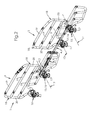
- Barrier 1 is brought to the place of assembly in the folded position ( figure 3 ), so that the jaws 16 connected to the front panel 2 face a spar 37.
- the jaws 16 of the front panel 2 are then placed on the beam 37, so as to be able to position the barrier 1 by sliding along the spar 37. It is then possible for example to put the panel 2 before abutting against the panel 35. head.
- the jaws 16 are then tightened by means of the handles 17, to block the front section 5 of the support arm 4 on the spar 37 (FIG. figure 4 ).
- the jaw 16 carried by the front panel 2 which is not integral with the support arm 4 is the jaw placed closest to the head panel.
- Such an arrangement advantageously makes it possible, when the barrier 1 is assembled on the spar 37, to leave the spar portion 37 immediately adjacent to the panel 35. head, corresponding to the portion of spar that will line the patient's head lying on the bed. Other equipment necessary for patient care may then be placed near the patient's head and bust.
- the barrier 1 is already positioned on the spar 37 of the bed 27.
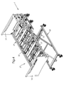
- the rear section 6 of the support arm 4 can, however, still pivot relative to the blocked front section 5 ( figure 5 ).
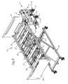
- the barrier 1 is then placed in the extended position, so that the support arm 4 is substantially parallel to the spar 37 and that the jaws 16 of the rear panel 3 can be placed and then tightened on the spar 37 of the bed 27 ( figure 6 ).
- the jaws 16 may be integral with the spar, and the support arm 4 is attached to the jaws for locking. Means for indexing the jaws 16 on the support arm 4 may be provided for this purpose.
- the barrier 1 thus assembled on the bed 27 can be dismounted easily, simply by loosening the jaws 16, then stored and stored in the folded position.
- a fixed spacing between the two panels 2, 3 can be determined, given by the position of the links 12, 13, 14 of the front panel 2 and the rear panel 3 on the support arm 4, in order to meet the requirements of security.
- an operator assembling the barrier 1 on the bed 27 does not need to determine itself this distance, at the risk of going against the norms.
- the retracted position of the panels 2, 3 makes it possible to fold them as close as possible to the spar 37, so as to release the sides of the sleeping surface 31 and facilitate both the access to the patient by the staff and the patient's exit from the patient. bed.
- the panels 2, 3 extend above the spar 37, bordering the surface 31 of the coating, to prevent the patient from falling.
- each panel 2, 3 is independent of the other. Indeed, it is for example possible to put the front panel 2 in the raised position and the rear panel 3 in the retracted position, for example to let the patient out of the bed 27 alone ( figure 7 ), the front panel 2 being available for the patient to use as support.
- the jaws 16 of the rear panel 3 may be loosened to put the barrier 1 in the folded position to achieve the same result. It is also possible to put the front panel 2 in the retracted position and the rear panel 3 in the raised position ( figure 8 ), for example to let the staff have access to the patient's head while ensuring the safety of the patient. It is however possible to put the two panels 2, 3 at the same time in the retracted position ( figure 9 ).
- the position of the barrier 1 on the spar 37 is for example determined by the length of the support arm 4 in the deployed position.
- the length of the beds can be standardized, so that for a given length of the support arm 4 in the deployed position, the abutment of the front panel 2 against the head panel 35 sets the other distances of the barrier 1 with respect to Bed panels 27 to meet safety requirements.
- a second barrier 1 can be assembled on the second spar 37 of the bed 27, so as to frame on either side the surface 31 of coating by the panels 2, 3 in the raised position.
- the barrier 1 thus formed offers the advantages of half-barriers, while avoiding the disadvantages of assembly and disassembly.
- the barrier 1 can easily be mounted on the bed 27, in the manner of an accessory, that is to say without affecting the design of the bed 27.
- the bed 27 can then be manufactured in series, so as to reduce manufacturing costs, and barrier 1 only to be installed when needed.
- the barrier 1 in the folded position, has a minimum size, so that it can be easily transported and stored.
- jaws 16 as fastening means allows a quick assembly, without tools, reducing the efforts of the operator.
Landscapes
- Health & Medical Sciences (AREA)
- Nursing (AREA)
- Life Sciences & Earth Sciences (AREA)
- Animal Behavior & Ethology (AREA)
- General Health & Medical Sciences (AREA)
- Public Health (AREA)
- Veterinary Medicine (AREA)
- Invalid Beds And Related Equipment (AREA)
Applications Claiming Priority (1)
| Application Number | Priority Date | Filing Date | Title |
|---|---|---|---|
| FR1157978A FR2979818B1 (fr) | 2011-09-08 | 2011-09-08 | Barriere de lit, notamment de lit medical, et procede de montage d'une telle barriere |
Publications (3)
| Publication Number | Publication Date |
|---|---|
| EP2567686A2 true EP2567686A2 (de) | 2013-03-13 |
| EP2567686A3 EP2567686A3 (de) | 2014-10-08 |
| EP2567686B1 EP2567686B1 (de) | 2017-06-14 |
Family
ID=46762986
Family Applications (1)
| Application Number | Title | Priority Date | Filing Date |
|---|---|---|---|
| EP12183617.5A Not-in-force EP2567686B1 (de) | 2011-09-08 | 2012-09-07 | Schutzgitter, insbesondere für Krankenbett, und Montageverfahren eines solchen Schutzgitters |
Country Status (2)
| Country | Link |
|---|---|
| EP (1) | EP2567686B1 (de) |
| FR (1) | FR2979818B1 (de) |
Cited By (3)
| Publication number | Priority date | Publication date | Assignee | Title |
|---|---|---|---|---|
| GB2542875A (en) * | 2016-04-18 | 2017-04-05 | Accora Ltd | Bed frame |
| CN109771153A (zh) * | 2019-03-19 | 2019-05-21 | 田雪莲 | 一种急诊科病人转移用病床 |
| EP3964186A1 (de) * | 2020-09-08 | 2022-03-09 | Hermann Bock GmbH | Seitengitter für ein bett |
Families Citing this family (2)
| Publication number | Priority date | Publication date | Assignee | Title |
|---|---|---|---|---|
| FR3067927B1 (fr) | 2017-06-26 | 2019-08-16 | Winncare France | Montant telescopique de barriere de lit et lit medical comprenant une telle barriere |
| FR3167541A1 (fr) | 2024-10-21 | 2026-04-24 | Winncare France | Lit médicalisé comprenant un chariot de transport et deux barrières latérales maintenues déployées frontalement sur le chariot |
Citations (4)
| Publication number | Priority date | Publication date | Assignee | Title |
|---|---|---|---|---|
| DE202004017406U1 (de) | 2004-11-09 | 2005-01-27 | Hermann Bock Gmbh | Vorrichtung zur Anordnung eines Seitengitters an einem Bett |
| US20060195984A1 (en) | 2005-03-07 | 2006-09-07 | Reza Hakamiun | Siderail for a hospital bed |
| US20080127415A1 (en) | 2004-03-12 | 2008-06-05 | Ruschke Jeffrey A | Variable Height Siderail for a Bed |
| EP1970038A1 (de) | 2007-03-13 | 2008-09-17 | Schell Industries | Bett mit kompakter zusammenklappbarer Sicherheitsbarriere |
Family Cites Families (5)
| Publication number | Priority date | Publication date | Assignee | Title |
|---|---|---|---|---|
| US354880A (en) * | 1886-12-28 | Safety attachment for scaffolds | ||
| US3248744A (en) * | 1964-12-14 | 1966-05-03 | Clyde B Hutt | Folding side guard attachment for hospital bed |
| US6389622B1 (en) * | 2000-08-03 | 2002-05-21 | Chiou-Feng Her | Hospital bed |
| TWM334708U (en) * | 2007-07-03 | 2008-06-21 | Optima Healthcare Inc | Handrail mechanism of bed frame |
| FR2934774B1 (fr) * | 2008-08-05 | 2010-09-17 | Hill Rom Sas | Lit de malade a barrieres. |
-
2011
- 2011-09-08 FR FR1157978A patent/FR2979818B1/fr not_active Expired - Fee Related
-
2012
- 2012-09-07 EP EP12183617.5A patent/EP2567686B1/de not_active Not-in-force
Patent Citations (4)
| Publication number | Priority date | Publication date | Assignee | Title |
|---|---|---|---|---|
| US20080127415A1 (en) | 2004-03-12 | 2008-06-05 | Ruschke Jeffrey A | Variable Height Siderail for a Bed |
| DE202004017406U1 (de) | 2004-11-09 | 2005-01-27 | Hermann Bock Gmbh | Vorrichtung zur Anordnung eines Seitengitters an einem Bett |
| US20060195984A1 (en) | 2005-03-07 | 2006-09-07 | Reza Hakamiun | Siderail for a hospital bed |
| EP1970038A1 (de) | 2007-03-13 | 2008-09-17 | Schell Industries | Bett mit kompakter zusammenklappbarer Sicherheitsbarriere |
Cited By (4)
| Publication number | Priority date | Publication date | Assignee | Title |
|---|---|---|---|---|
| GB2542875A (en) * | 2016-04-18 | 2017-04-05 | Accora Ltd | Bed frame |
| GB2542875B (en) * | 2016-04-18 | 2017-10-25 | Accora Ltd | Bed frame |
| CN109771153A (zh) * | 2019-03-19 | 2019-05-21 | 田雪莲 | 一种急诊科病人转移用病床 |
| EP3964186A1 (de) * | 2020-09-08 | 2022-03-09 | Hermann Bock GmbH | Seitengitter für ein bett |
Also Published As
| Publication number | Publication date |
|---|---|
| FR2979818A1 (fr) | 2013-03-15 |
| FR2979818B1 (fr) | 2017-01-06 |
| EP2567686B1 (de) | 2017-06-14 |
| EP2567686A3 (de) | 2014-10-08 |
Similar Documents
| Publication | Publication Date | Title |
|---|---|---|
| EP2567686B1 (de) | Schutzgitter, insbesondere für Krankenbett, und Montageverfahren eines solchen Schutzgitters | |
| EP2029081B1 (de) | Operationstisch-führungsvorrichtung aus führungsarmen, die lösbar am operationstisch befestigt werden, und operationstisch mit diesen armen | |
| EP2116217B1 (de) | Bett mit faltbarem Bettrahmen | |
| WO2009156660A2 (fr) | Perfectionnement aux paravents de protection contre les emissions de rayonnements ionisants | |
| EP2210577B1 (de) | Bettrost | |
| EP0365455A1 (de) | Transportvorrichtung für Patienten | |
| FR3073734B1 (fr) | Lit compact configure pour adopter une configuration chariot facilitant son transport | |
| FR2937359A1 (fr) | Ensemble de lisse et sous-lisse solidaires pour echafaudage, procede de montage et echafaudage obtenu. | |
| EP2695591B1 (de) | Patientenbett mit erleichterter Montage, und Montageverfahren eines solchen Betts | |
| EP2450017B1 (de) | Verfahren zur Bettmontage | |
| FR2976791A1 (fr) | Barriere de lit escamotable | |
| FR3012511A1 (fr) | Echelle equipee d'un stabilisateur demontable en deux parties | |
| EP3141152B1 (de) | Zusammenklappbare konpakte tisch, besonders für schienenfahrzeug | |
| EP1721550B1 (de) | Krankenbett mit vollständiger Seitenlehne | |
| FR2794643A1 (fr) | Chaise pliante destinee au transport d'une personne | |
| WO2021013484A1 (fr) | Dispositif de levage et de transport d'une personne | |
| FR2908804A1 (fr) | Garde-corps d'echafaudage a montage en securite | |
| FR2947849A1 (fr) | Jambe d'appui ou de stabilisation telescopique et dispositif comprenant une telle jambe | |
| FR2661088A1 (fr) | Perfectionnements aux fauteuils roulants pour handicapes. | |
| FR2990848A1 (fr) | Chariot de brancard muni de barrieres indexees multipositions | |
| FR2934774A1 (fr) | Lit de malade a barrieres. | |
| FR2919479A1 (fr) | Lit medicalise avec barriere retractable | |
| FR2711522A1 (fr) | Lit médical à barrière de sécurité. | |
| EP0580456B1 (de) | Gerüst | |
| FR2861584A1 (fr) | Dispositif de suspension d'une personne handicapee |
Legal Events
| Date | Code | Title | Description |
|---|---|---|---|
| PUAI | Public reference made under article 153(3) epc to a published international application that has entered the european phase |
Free format text: ORIGINAL CODE: 0009012 |
|
| AK | Designated contracting states |
Kind code of ref document: A2 Designated state(s): AL AT BE BG CH CY CZ DE DK EE ES FI FR GB GR HR HU IE IS IT LI LT LU LV MC MK MT NL NO PL PT RO RS SE SI SK SM TR |
|
| AX | Request for extension of the european patent |
Extension state: BA ME |
|
| RIC1 | Information provided on ipc code assigned before grant |
Ipc: A61G 7/05 20060101AFI20140429BHEP Ipc: A61G 7/012 20060101ALN20140429BHEP |
|
| PUAL | Search report despatched |
Free format text: ORIGINAL CODE: 0009013 |
|
| AK | Designated contracting states |
Kind code of ref document: A3 Designated state(s): AL AT BE BG CH CY CZ DE DK EE ES FI FR GB GR HR HU IE IS IT LI LT LU LV MC MK MT NL NO PL PT RO RS SE SI SK SM TR |
|
| AX | Request for extension of the european patent |
Extension state: BA ME |
|
| RIC1 | Information provided on ipc code assigned before grant |
Ipc: A61G 7/05 20060101AFI20140904BHEP Ipc: A61G 7/012 20060101ALN20140904BHEP |
|
| 17P | Request for examination filed |
Effective date: 20141203 |
|
| RBV | Designated contracting states (corrected) |
Designated state(s): AL AT BE BG CH CY CZ DE DK EE ES FI FR GB GR HR HU IE IS IT LI LT LU LV MC MK MT NL NO PL PT RO RS SE SI SK SM TR |
|
| RIC1 | Information provided on ipc code assigned before grant |
Ipc: A61G 7/05 20060101AFI20161116BHEP Ipc: A61G 7/012 20060101ALN20161116BHEP |
|
| GRAP | Despatch of communication of intention to grant a patent |
Free format text: ORIGINAL CODE: EPIDOSNIGR1 |
|
| RAP1 | Party data changed (applicant data changed or rights of an application transferred) |
Owner name: MEDICATLANTIC |
|
| INTG | Intention to grant announced |
Effective date: 20170213 |
|
| GRAS | Grant fee paid |
Free format text: ORIGINAL CODE: EPIDOSNIGR3 |
|
| GRAA | (expected) grant |
Free format text: ORIGINAL CODE: 0009210 |
|
| AK | Designated contracting states |
Kind code of ref document: B1 Designated state(s): AL AT BE BG CH CY CZ DE DK EE ES FI FR GB GR HR HU IE IS IT LI LT LU LV MC MK MT NL NO PL PT RO RS SE SI SK SM TR |
|
| REG | Reference to a national code |
Ref country code: GB Ref legal event code: FG4D Free format text: NOT ENGLISH |
|
| REG | Reference to a national code |
Ref country code: CH Ref legal event code: EP Ref country code: AT Ref legal event code: REF Ref document number: 900285 Country of ref document: AT Kind code of ref document: T Effective date: 20170615 |
|
| REG | Reference to a national code |
Ref country code: IE Ref legal event code: FG4D Free format text: LANGUAGE OF EP DOCUMENT: FRENCH |
|
| REG | Reference to a national code |
Ref country code: DE Ref legal event code: R096 Ref document number: 602012033377 Country of ref document: DE |
|
| REG | Reference to a national code |
Ref country code: FR Ref legal event code: PLFP Year of fee payment: 6 |
|
| REG | Reference to a national code |
Ref country code: NL Ref legal event code: MP Effective date: 20170614 |
|
| REG | Reference to a national code |
Ref country code: LT Ref legal event code: MG4D |
|
| PG25 | Lapsed in a contracting state [announced via postgrant information from national office to epo] |
Ref country code: NO Free format text: LAPSE BECAUSE OF FAILURE TO SUBMIT A TRANSLATION OF THE DESCRIPTION OR TO PAY THE FEE WITHIN THE PRESCRIBED TIME-LIMIT Effective date: 20170914 Ref country code: GR Free format text: LAPSE BECAUSE OF FAILURE TO SUBMIT A TRANSLATION OF THE DESCRIPTION OR TO PAY THE FEE WITHIN THE PRESCRIBED TIME-LIMIT Effective date: 20170915 Ref country code: LT Free format text: LAPSE BECAUSE OF FAILURE TO SUBMIT A TRANSLATION OF THE DESCRIPTION OR TO PAY THE FEE WITHIN THE PRESCRIBED TIME-LIMIT Effective date: 20170614 Ref country code: ES Free format text: LAPSE BECAUSE OF FAILURE TO SUBMIT A TRANSLATION OF THE DESCRIPTION OR TO PAY THE FEE WITHIN THE PRESCRIBED TIME-LIMIT Effective date: 20170614 Ref country code: HR Free format text: LAPSE BECAUSE OF FAILURE TO SUBMIT A TRANSLATION OF THE DESCRIPTION OR TO PAY THE FEE WITHIN THE PRESCRIBED TIME-LIMIT Effective date: 20170614 Ref country code: FI Free format text: LAPSE BECAUSE OF FAILURE TO SUBMIT A TRANSLATION OF THE DESCRIPTION OR TO PAY THE FEE WITHIN THE PRESCRIBED TIME-LIMIT Effective date: 20170614 |
|
| REG | Reference to a national code |
Ref country code: AT Ref legal event code: MK05 Ref document number: 900285 Country of ref document: AT Kind code of ref document: T Effective date: 20170614 |
|
| PG25 | Lapsed in a contracting state [announced via postgrant information from national office to epo] |
Ref country code: RS Free format text: LAPSE BECAUSE OF FAILURE TO SUBMIT A TRANSLATION OF THE DESCRIPTION OR TO PAY THE FEE WITHIN THE PRESCRIBED TIME-LIMIT Effective date: 20170614 Ref country code: LV Free format text: LAPSE BECAUSE OF FAILURE TO SUBMIT A TRANSLATION OF THE DESCRIPTION OR TO PAY THE FEE WITHIN THE PRESCRIBED TIME-LIMIT Effective date: 20170614 Ref country code: SE Free format text: LAPSE BECAUSE OF FAILURE TO SUBMIT A TRANSLATION OF THE DESCRIPTION OR TO PAY THE FEE WITHIN THE PRESCRIBED TIME-LIMIT Effective date: 20170614 Ref country code: NL Free format text: LAPSE BECAUSE OF FAILURE TO SUBMIT A TRANSLATION OF THE DESCRIPTION OR TO PAY THE FEE WITHIN THE PRESCRIBED TIME-LIMIT Effective date: 20170614 Ref country code: BG Free format text: LAPSE BECAUSE OF FAILURE TO SUBMIT A TRANSLATION OF THE DESCRIPTION OR TO PAY THE FEE WITHIN THE PRESCRIBED TIME-LIMIT Effective date: 20170914 |
|
| PG25 | Lapsed in a contracting state [announced via postgrant information from national office to epo] |
Ref country code: CZ Free format text: LAPSE BECAUSE OF FAILURE TO SUBMIT A TRANSLATION OF THE DESCRIPTION OR TO PAY THE FEE WITHIN THE PRESCRIBED TIME-LIMIT Effective date: 20170614 Ref country code: RO Free format text: LAPSE BECAUSE OF FAILURE TO SUBMIT A TRANSLATION OF THE DESCRIPTION OR TO PAY THE FEE WITHIN THE PRESCRIBED TIME-LIMIT Effective date: 20170614 Ref country code: AT Free format text: LAPSE BECAUSE OF FAILURE TO SUBMIT A TRANSLATION OF THE DESCRIPTION OR TO PAY THE FEE WITHIN THE PRESCRIBED TIME-LIMIT Effective date: 20170614 Ref country code: SK Free format text: LAPSE BECAUSE OF FAILURE TO SUBMIT A TRANSLATION OF THE DESCRIPTION OR TO PAY THE FEE WITHIN THE PRESCRIBED TIME-LIMIT Effective date: 20170614 Ref country code: EE Free format text: LAPSE BECAUSE OF FAILURE TO SUBMIT A TRANSLATION OF THE DESCRIPTION OR TO PAY THE FEE WITHIN THE PRESCRIBED TIME-LIMIT Effective date: 20170614 |
|
| PG25 | Lapsed in a contracting state [announced via postgrant information from national office to epo] |
Ref country code: SM Free format text: LAPSE BECAUSE OF FAILURE TO SUBMIT A TRANSLATION OF THE DESCRIPTION OR TO PAY THE FEE WITHIN THE PRESCRIBED TIME-LIMIT Effective date: 20170614 Ref country code: IT Free format text: LAPSE BECAUSE OF FAILURE TO SUBMIT A TRANSLATION OF THE DESCRIPTION OR TO PAY THE FEE WITHIN THE PRESCRIBED TIME-LIMIT Effective date: 20170614 Ref country code: IS Free format text: LAPSE BECAUSE OF FAILURE TO SUBMIT A TRANSLATION OF THE DESCRIPTION OR TO PAY THE FEE WITHIN THE PRESCRIBED TIME-LIMIT Effective date: 20171014 Ref country code: PL Free format text: LAPSE BECAUSE OF FAILURE TO SUBMIT A TRANSLATION OF THE DESCRIPTION OR TO PAY THE FEE WITHIN THE PRESCRIBED TIME-LIMIT Effective date: 20170614 |
|
| REG | Reference to a national code |
Ref country code: DE Ref legal event code: R097 Ref document number: 602012033377 Country of ref document: DE |
|
| REG | Reference to a national code |
Ref country code: DE Ref legal event code: R119 Ref document number: 602012033377 Country of ref document: DE |
|
| PLBE | No opposition filed within time limit |
Free format text: ORIGINAL CODE: 0009261 |
|
| STAA | Information on the status of an ep patent application or granted ep patent |
Free format text: STATUS: NO OPPOSITION FILED WITHIN TIME LIMIT |
|
| PG25 | Lapsed in a contracting state [announced via postgrant information from national office to epo] |
Ref country code: DK Free format text: LAPSE BECAUSE OF FAILURE TO SUBMIT A TRANSLATION OF THE DESCRIPTION OR TO PAY THE FEE WITHIN THE PRESCRIBED TIME-LIMIT Effective date: 20170614 |
|
| REG | Reference to a national code |
Ref country code: CH Ref legal event code: PL |
|
| 26N | No opposition filed |
Effective date: 20180315 |
|
| GBPC | Gb: european patent ceased through non-payment of renewal fee |
Effective date: 20170914 |
|
| PG25 | Lapsed in a contracting state [announced via postgrant information from national office to epo] |
Ref country code: MC Free format text: LAPSE BECAUSE OF FAILURE TO SUBMIT A TRANSLATION OF THE DESCRIPTION OR TO PAY THE FEE WITHIN THE PRESCRIBED TIME-LIMIT Effective date: 20170614 |
|
| REG | Reference to a national code |
Ref country code: FR Ref legal event code: CD Owner name: WINNCARE FRANCE, FR Effective date: 20180517 |
|
| REG | Reference to a national code |
Ref country code: IE Ref legal event code: MM4A |
|
| REG | Reference to a national code |
Ref country code: BE Ref legal event code: MM Effective date: 20170930 |
|
| PG25 | Lapsed in a contracting state [announced via postgrant information from national office to epo] |
Ref country code: LU Free format text: LAPSE BECAUSE OF NON-PAYMENT OF DUE FEES Effective date: 20170907 |
|
| PG25 | Lapsed in a contracting state [announced via postgrant information from national office to epo] |
Ref country code: LI Free format text: LAPSE BECAUSE OF NON-PAYMENT OF DUE FEES Effective date: 20170930 Ref country code: CH Free format text: LAPSE BECAUSE OF NON-PAYMENT OF DUE FEES Effective date: 20170930 Ref country code: IE Free format text: LAPSE BECAUSE OF NON-PAYMENT OF DUE FEES Effective date: 20170907 Ref country code: DE Free format text: LAPSE BECAUSE OF NON-PAYMENT OF DUE FEES Effective date: 20180404 Ref country code: GB Free format text: LAPSE BECAUSE OF NON-PAYMENT OF DUE FEES Effective date: 20170914 |
|
| PG25 | Lapsed in a contracting state [announced via postgrant information from national office to epo] |
Ref country code: SI Free format text: LAPSE BECAUSE OF FAILURE TO SUBMIT A TRANSLATION OF THE DESCRIPTION OR TO PAY THE FEE WITHIN THE PRESCRIBED TIME-LIMIT Effective date: 20170614 Ref country code: BE Free format text: LAPSE BECAUSE OF NON-PAYMENT OF DUE FEES Effective date: 20170930 |
|
| REG | Reference to a national code |
Ref country code: FR Ref legal event code: PLFP Year of fee payment: 7 |
|
| PG25 | Lapsed in a contracting state [announced via postgrant information from national office to epo] |
Ref country code: MT Free format text: LAPSE BECAUSE OF FAILURE TO SUBMIT A TRANSLATION OF THE DESCRIPTION OR TO PAY THE FEE WITHIN THE PRESCRIBED TIME-LIMIT Effective date: 20170614 |
|
| PG25 | Lapsed in a contracting state [announced via postgrant information from national office to epo] |
Ref country code: HU Free format text: LAPSE BECAUSE OF FAILURE TO SUBMIT A TRANSLATION OF THE DESCRIPTION OR TO PAY THE FEE WITHIN THE PRESCRIBED TIME-LIMIT; INVALID AB INITIO Effective date: 20120907 |
|
| PG25 | Lapsed in a contracting state [announced via postgrant information from national office to epo] |
Ref country code: CY Free format text: LAPSE BECAUSE OF NON-PAYMENT OF DUE FEES Effective date: 20170614 |
|
| PG25 | Lapsed in a contracting state [announced via postgrant information from national office to epo] |
Ref country code: MK Free format text: LAPSE BECAUSE OF FAILURE TO SUBMIT A TRANSLATION OF THE DESCRIPTION OR TO PAY THE FEE WITHIN THE PRESCRIBED TIME-LIMIT Effective date: 20170614 |
|
| PG25 | Lapsed in a contracting state [announced via postgrant information from national office to epo] |
Ref country code: TR Free format text: LAPSE BECAUSE OF FAILURE TO SUBMIT A TRANSLATION OF THE DESCRIPTION OR TO PAY THE FEE WITHIN THE PRESCRIBED TIME-LIMIT Effective date: 20170614 |
|
| PG25 | Lapsed in a contracting state [announced via postgrant information from national office to epo] |
Ref country code: PT Free format text: LAPSE BECAUSE OF FAILURE TO SUBMIT A TRANSLATION OF THE DESCRIPTION OR TO PAY THE FEE WITHIN THE PRESCRIBED TIME-LIMIT Effective date: 20170614 |
|
| PG25 | Lapsed in a contracting state [announced via postgrant information from national office to epo] |
Ref country code: AL Free format text: LAPSE BECAUSE OF FAILURE TO SUBMIT A TRANSLATION OF THE DESCRIPTION OR TO PAY THE FEE WITHIN THE PRESCRIBED TIME-LIMIT Effective date: 20170614 |
|
| PGFP | Annual fee paid to national office [announced via postgrant information from national office to epo] |
Ref country code: FR Payment date: 20230915 Year of fee payment: 12 |
|
| PG25 | Lapsed in a contracting state [announced via postgrant information from national office to epo] |
Ref country code: FR Free format text: LAPSE BECAUSE OF NON-PAYMENT OF DUE FEES Effective date: 20240930 |