EP2567686A2 - Bed rail, especially of a medical bed, and method for mounting such a rail - Google Patents
Bed rail, especially of a medical bed, and method for mounting such a rail Download PDFInfo
- Publication number
- EP2567686A2 EP2567686A2 EP12183617A EP12183617A EP2567686A2 EP 2567686 A2 EP2567686 A2 EP 2567686A2 EP 12183617 A EP12183617 A EP 12183617A EP 12183617 A EP12183617 A EP 12183617A EP 2567686 A2 EP2567686 A2 EP 2567686A2
- Authority
- EP
- European Patent Office
- Prior art keywords
- bed
- section
- panel
- barrier
- support arm
- Prior art date
- Legal status (The legal status is an assumption and is not a legal conclusion. Google has not performed a legal analysis and makes no representation as to the accuracy of the status listed.)
- Granted
Links
- 238000000034 method Methods 0.000 title claims abstract description 6
- 230000004888 barrier function Effects 0.000 claims description 85
- 125000006850 spacer group Chemical group 0.000 claims description 10
- 239000011248 coating agent Substances 0.000 claims description 4
- 238000000576 coating method Methods 0.000 claims description 4
- 230000000903 blocking effect Effects 0.000 description 2
- 239000007787 solid Substances 0.000 description 2
- 229940079593 drug Drugs 0.000 description 1
- 239000003814 drug Substances 0.000 description 1
- 238000004519 manufacturing process Methods 0.000 description 1
- 230000000474 nursing effect Effects 0.000 description 1
- 230000007170 pathology Effects 0.000 description 1
- 230000036515 potency Effects 0.000 description 1
- 230000001105 regulatory effect Effects 0.000 description 1
- 238000010079 rubber tapping Methods 0.000 description 1
Images


Classifications
-
- A—HUMAN NECESSITIES
- A61—MEDICAL OR VETERINARY SCIENCE; HYGIENE
- A61G—TRANSPORT, PERSONAL CONVEYANCES, OR ACCOMMODATION SPECIALLY ADAPTED FOR PATIENTS OR DISABLED PERSONS; OPERATING TABLES OR CHAIRS; CHAIRS FOR DENTISTRY; FUNERAL DEVICES
- A61G7/00—Beds specially adapted for nursing; Devices for lifting patients or disabled persons
- A61G7/05—Parts, details or accessories of beds
- A61G7/0507—Side-rails
- A61G7/0508—Side-rails characterised by a particular connection mechanism
- A61G7/0509—Side-rails characterised by a particular connection mechanism sliding or pivoting downwards
-
- A—HUMAN NECESSITIES
- A61—MEDICAL OR VETERINARY SCIENCE; HYGIENE
- A61G—TRANSPORT, PERSONAL CONVEYANCES, OR ACCOMMODATION SPECIALLY ADAPTED FOR PATIENTS OR DISABLED PERSONS; OPERATING TABLES OR CHAIRS; CHAIRS FOR DENTISTRY; FUNERAL DEVICES
- A61G7/00—Beds specially adapted for nursing; Devices for lifting patients or disabled persons
- A61G7/05—Parts, details or accessories of beds
- A61G7/0507—Side-rails
- A61G7/0512—Side-rails characterised by customised length
- A61G7/0513—Side-rails characterised by customised length covering particular sections of the bed, e.g. one or more partial side-rail sections along the bed
-
- A—HUMAN NECESSITIES
- A61—MEDICAL OR VETERINARY SCIENCE; HYGIENE
- A61G—TRANSPORT, PERSONAL CONVEYANCES, OR ACCOMMODATION SPECIALLY ADAPTED FOR PATIENTS OR DISABLED PERSONS; OPERATING TABLES OR CHAIRS; CHAIRS FOR DENTISTRY; FUNERAL DEVICES
- A61G7/00—Beds specially adapted for nursing; Devices for lifting patients or disabled persons
- A61G7/05—Parts, details or accessories of beds
- A61G7/0507—Side-rails
- A61G7/0518—Side-rails quickly removable
-
- A—HUMAN NECESSITIES
- A61—MEDICAL OR VETERINARY SCIENCE; HYGIENE
- A61G—TRANSPORT, PERSONAL CONVEYANCES, OR ACCOMMODATION SPECIALLY ADAPTED FOR PATIENTS OR DISABLED PERSONS; OPERATING TABLES OR CHAIRS; CHAIRS FOR DENTISTRY; FUNERAL DEVICES
- A61G7/00—Beds specially adapted for nursing; Devices for lifting patients or disabled persons
- A61G7/002—Beds specially adapted for nursing; Devices for lifting patients or disabled persons having adjustable mattress frame
- A61G7/012—Beds specially adapted for nursing; Devices for lifting patients or disabled persons having adjustable mattress frame raising or lowering of the whole mattress frame
Definitions
- the invention relates to the field of medical beds, and more particularly to barriers for medical beds.
- Medical beds are used both in hospitals, nursing homes, and patients' homes.
- Medical beds have been developed to meet the specific needs of patients, depending on the pathologies they present. Thus, medical beds are intended to relieve patients by facilitating for example the change of position, the dispensation of care or taking medication.
- Medical beds also preferably allow easier access to the patient by the staff providing the care.
- the beds may further include barriers, preventing the patient from falling.
- the barriers are generally placed on either side of the sleeping surface, and may extend over all or part of the length of the bed.
- the first type is the simple barrier, extending over the entire length of the bed.
- the document DE 20 2004 017 406 (BOCK) describes an example of such a barrier.
- the second type is the three-quarter barrier, extending over only a portion of the length of the bed.
- the third type is the half-barrier that allows to use two barrier panels, or half-barrier, independently.
- each panel is mounted on one side of the bed, and can for example be lowered while leaving the other panel in place.
- half-barriers are particularly used in hospitals.
- HILLROM presents an example of such a barrier, comprising two panels, placed on each side of the bed. Each panel is fixed on the bed in a specific position, and is retractable by rotation about a longitudinal axis.
- the document EP 1 970 038 (SCHELL) describes a barrier operating on a principle similar to that of the document US 2006/0195984 supra.
- HILLROM The document US 2008/0127415 (HILLROM) describes a barrier comprising two panels fixed independently of one another on the bed, retractable by rotation about a transverse axis.
- the barrier panels are conventionally fixed with a spacing, and are not intended to be removed, the barriers in two panels of the state of the art being integrated into the frame of the bed , to be fixed permanently on the bed.
- a first object of the invention is to provide a bed barrier comprising two independent panels, which can be easily removed. of the bed and assembly again while respecting a determined spacing between the panels.
- a second object of the invention is to provide a bed barrier comprising two panels, the barrier can be easily mounted and disassembled from the bed.
- a third object of the invention is to provide an easily transportable bed barrier.
- a fourth object of the invention is to provide a removable bed barrier that disassembles and mounts with minimal effort.
- a fifth object of the invention is to provide a removable bed barrier facilitating access to the patient, while giving the patient autonomy to get out of bed.
- the invention proposes a bed barrier, in particular a medical bed, comprising a support arm provided with fixing means on a spar of the bed, the barrier also comprising a first panel, referred to as a front panel, in connection with with the support arm, the support arm further having a front section and a rear section.
- the barrier comprises a second panel said rear panel and in that the front panel is in connection with the front section of the arm and the rear panel is in connection with the rear section of the arm.
- the barrier thus formed makes it possible to combine the advantages of a barrier with those of two half-barriers, while respecting the barrier standards for hospital beds.
- the raised position of the front panel ensures the safety of a patient lying on the bed, while the retracted position allows medical personnel to access the patient on the bed and provide the necessary care.
- the raised position of the back panel ensures the safety of a patient lying on the bed, while the retracted position allows the patient to get out of bed while keeping the front panel in the raised position.
- the fastening means are clamping jaws, allowing a single operator to easily assemble and dismount the barrier without tools.
- the front panel is mounted on a first jaw integral with the front section of the support arm, the rear panel being mounted on two jaws integral with the rear section of the support arm.
- the front panel is mounted on a first jaw integral with the front section of the support arm, the rear panel being mounted on a single jaw secured to the rear section of the support arm.
- the barrier In the deployed position, the barrier is then used on the bed.
- the folded position facilitates both storage and transportation by reducing the size of the barrier.
- the front section is rotated about a first axis on a first end portion of a spacer and the rear section is rotated about a second axis, parallel to the first axis, on a second end portion. of the spacer.
- the spacer thus makes it possible to fold the portions of the arm towards one another, being substantially parallel to one another, without the sections overlapping.
- the invention provides a bed, in particular a medical bed, comprising an upper frame defining a sleeping surface and comprising a spar, and comprising a barrier as described above fixed on the spar.
- the functions of the bed can thus be adapted to the needs of the patient, by mounting or dismounting the barrier of the bed.
- a bed barrier 1 comprising two panels 2, 3, called front panel 2 and rear panel 3, connected to a support arm 4.
- Per panel it is designated a guardrail element of the barrier, preventing a patient of the bed from falling.
- the panels 2, 3 can be solid panels, perforated panels, lattice panels, or panels formed of bars
- the front section 5 abuts the rear section 6.
- the support arm 4 comprises a spacer 9 connecting the front section and the rear section. More specifically, the front section 5 is pivotally mounted on a first end portion of the spacer 9 relative to a first axis and the rear section 6 is pivotally mounted on the second end portion 11 of the spacer 9 relative to a second axis parallel to the first axis.
- the spacer 9 thus allows, when the barrier 1 is in the deployed position, to keep the two sections 5, 6 at the same height relative to their axes of rotation on the spacer 9.
- the two sections 5, 6 may be substantially parallel to each other, despite the presence of the panels 2, 3 carried by the sections 5, 6.
- the front panel 2 is in connection with the front section 5 of the support arm 4 while the rear panel 3 is in connection with the rear section 6 of the support arm 4.
- connection with here refers to the characteristic that there is at least one bond between two bodies, in this case between a panel 2, 3 and a section 5, 6.
- the front panel 2 comprises a first link 12 on the front section 5 and the rear panel 3 comprises a second link 13 and a third link 14 on the rear section 6, the third link 14 being closer to the second end 8 of the support arm 4 than the second link 13.
- the number of links of each panel 2, 3 on a section 5, 6 of the support arm 4 may however be adapted according to the design needs.
- each panel 2, 3 is in connection with a section 5, 6 distinct from the support arm 4, the connection of the front panel 2 to the front section 5 of the support arm 4 is separated from the connection of the panel 3 rearward on the rear section 6 of the support arm 4, that is to say a distance determined during the design of the barrier 1 can be measured between each link of the front panel 2 on the support arm 4 and each rear panel link 3 on the support arm 4, measured along the support arm 4 when the barrier 1 is in the deployed position.
- the two panels 2, 3 are not in contact with each other, and a spacing in the direction of the support arm 4 in deployed position can be measured, corresponding to the distance between the first link 12 and the second link 13.
- the barrier 1 further comprises means 15 for attachment to a beam 37 of the bed, carried by the support arm 4.
- the fixing means 15 are integral with the support arm 4, and the panels 2, 3 are in connection with the fixing means 15.
- the fixing means 15 are removable means, that is to say that they can be easily disassembled and assembled on the bed, preferably without tools.
- the fixing means 15 are in the form of jaws 16 adjustable by means of a handle 17 that can be manually operated.
- the blocking of the barrier 1 on the bed can thus be obtained by clamping the jaws 16.
- the mounting of the barrier 1 on the bed will be described with greater precision later.
- each panel 2, 3 is for example in the form of a substantially planar element, that is to say that it has larger dimensions in two directions than those in the third direction. It can thus for example be a solid panel, or a trellis.
- each panel 2, 3 comprises two uprights 18 connected by at least one bar 19.
- the uprights 18 are connected by a series of parallel bars 19, for example three bars 19.
- Each upright 18 is in the form of a bent tube, comprising a straight portion.
- the front panel 2 comprises an upright 18 of which a lower end portion 21 is pivotally mounted on the front section 5 of the support arm 4 about an axis parallel to the transverse direction Y2 of the front panel 2 to form the first link 12 while the two uprights 18 of the rear panel 3 have a lower end portion 21, both of which are pivotally mounted on the rear section 6 of the support arm 4 about axes parallel to the transverse direction Y3 of the rear panel 3 to form respectively the second connection 13 and the third link 14.
- each link 12, 13, 14 is carried by a jaw 16 integral with the support arm 4, two jaws 16 being fixed on the rear section 6 and a jaw 16 being fixed on the front section 5.
- a single jaw 16 fixed on the rear section 6 may suffice, so that a connection, for example the third link 14, of the rear panel 3 on the arm is then directly carried out on the rear section 6 of the arm 4.
- the two uprights 18 of the rear panel 3 are then respectively mounted on one of the jaws 16 of the rear section 6, each pivoting about an axis parallel to the transverse direction Y3 of the rear panel 3, to form the second connection 13 and the third link 14.
- a single upright 18 of the front panel 2 is mounted on the jaw 16 of the front section 5, pivoting about an axis parallel to the transverse direction Y2, to form the first link 12.
- the lower end portion 21 of the second 18 amount of the front panel 2 is also mounted on a fourth jaw 16, which may however not be secured to the support arm 4.
- the links 12, 13, 14 of the panels 2, 3 on the support arm 4 are shown in FIG. figure 2 by the transverse axis of rotation of the panels 2, 3 on the jaws 16.
- the spacing between the first link 12 and the second link 13 may advantageously be determined so that the panels 2, 3 do not overlap and the amount 18 of the front panel 2 mounted on the first link 12 is at a distance from the post 18 of the adjacent rear panel 3, mounted on the second link 13.
- the bar 19 connecting the two uprights 18 must advantageously be substantially parallel to the longitudinal direction X2, X3.
- the jaws 16 must be aligned in the longitudinal direction X2, X3.
- the straight portions 20 of the two uprights 18 of each panel 2, 3 are arranged so as to be substantially parallel to each other.
- each of the two panels 2, 3 can be manipulated to be put in the position raised or in the retracted position without the position of the other panel being influenced.
- the barrier 1 comprises means 22 for blocking each panel 2, 3 in the raised position.
- one of the uprights 18 comprises a tongue 23 provided with an opening 24 and the corresponding jaw 16, that is to say the jaw 16 on which is mounted the amount 18 considered, comprises also an opening 25, for example threaded.
- the two openings 24, 25 are in register, and an indexing finger 26 is inserted into the two openings 24, 25.
- the finger 26 may comprise a threaded portion cooperating with tapping the opening 24 on the jaw 16 to lock the finger 26.
- the bed 27 comprises a lower frame 28, which can be mounted on wheels, and an upper frame 29 carrying a bed base 30 to define a surface 31 of coating.
- Means 32 for adjusting the height of the bed base 30 with respect to the lower frame 28, for example a crossbar system, can be interposed between the lower frame 28 and the upper frame 29.
- the bed 27 has a region 33 of head, corresponding to the portion of the bed base 30 intended to support in particular the head and the torso of a patient, and a region 34 of feet, corresponding to the portion of the bed base 30 intended to support in particular the legs and feet of the patient.
- Means for raising the head portion of the bed base 30 relative to the foot portion, and vice versa, may be provided on the bed 27.
- Bed 27 may also include a head panel and a foot panel 36.
- the upper frame 29 includes in particular two longitudinal members 37 extending on each side of the bed 27 along its length, for example between the head panel 35 and the foot panel 36.
- Barrier 1 is brought to the place of assembly in the folded position ( figure 3 ), so that the jaws 16 connected to the front panel 2 face a spar 37.
- the jaws 16 of the front panel 2 are then placed on the beam 37, so as to be able to position the barrier 1 by sliding along the spar 37. It is then possible for example to put the panel 2 before abutting against the panel 35. head.
- the jaws 16 are then tightened by means of the handles 17, to block the front section 5 of the support arm 4 on the spar 37 (FIG. figure 4 ).
- the jaw 16 carried by the front panel 2 which is not integral with the support arm 4 is the jaw placed closest to the head panel.
- Such an arrangement advantageously makes it possible, when the barrier 1 is assembled on the spar 37, to leave the spar portion 37 immediately adjacent to the panel 35. head, corresponding to the portion of spar that will line the patient's head lying on the bed. Other equipment necessary for patient care may then be placed near the patient's head and bust.
- the barrier 1 is already positioned on the spar 37 of the bed 27.
- the rear section 6 of the support arm 4 can, however, still pivot relative to the blocked front section 5 ( figure 5 ).
- the barrier 1 is then placed in the extended position, so that the support arm 4 is substantially parallel to the spar 37 and that the jaws 16 of the rear panel 3 can be placed and then tightened on the spar 37 of the bed 27 ( figure 6 ).
- the jaws 16 may be integral with the spar, and the support arm 4 is attached to the jaws for locking. Means for indexing the jaws 16 on the support arm 4 may be provided for this purpose.
- the barrier 1 thus assembled on the bed 27 can be dismounted easily, simply by loosening the jaws 16, then stored and stored in the folded position.
- a fixed spacing between the two panels 2, 3 can be determined, given by the position of the links 12, 13, 14 of the front panel 2 and the rear panel 3 on the support arm 4, in order to meet the requirements of security.
- an operator assembling the barrier 1 on the bed 27 does not need to determine itself this distance, at the risk of going against the norms.
- the retracted position of the panels 2, 3 makes it possible to fold them as close as possible to the spar 37, so as to release the sides of the sleeping surface 31 and facilitate both the access to the patient by the staff and the patient's exit from the patient. bed.
- the panels 2, 3 extend above the spar 37, bordering the surface 31 of the coating, to prevent the patient from falling.
- each panel 2, 3 is independent of the other. Indeed, it is for example possible to put the front panel 2 in the raised position and the rear panel 3 in the retracted position, for example to let the patient out of the bed 27 alone ( figure 7 ), the front panel 2 being available for the patient to use as support.
- the jaws 16 of the rear panel 3 may be loosened to put the barrier 1 in the folded position to achieve the same result. It is also possible to put the front panel 2 in the retracted position and the rear panel 3 in the raised position ( figure 8 ), for example to let the staff have access to the patient's head while ensuring the safety of the patient. It is however possible to put the two panels 2, 3 at the same time in the retracted position ( figure 9 ).
- the position of the barrier 1 on the spar 37 is for example determined by the length of the support arm 4 in the deployed position.
- the length of the beds can be standardized, so that for a given length of the support arm 4 in the deployed position, the abutment of the front panel 2 against the head panel 35 sets the other distances of the barrier 1 with respect to Bed panels 27 to meet safety requirements.
- a second barrier 1 can be assembled on the second spar 37 of the bed 27, so as to frame on either side the surface 31 of coating by the panels 2, 3 in the raised position.
- the barrier 1 thus formed offers the advantages of half-barriers, while avoiding the disadvantages of assembly and disassembly.
- the barrier 1 can easily be mounted on the bed 27, in the manner of an accessory, that is to say without affecting the design of the bed 27.
- the bed 27 can then be manufactured in series, so as to reduce manufacturing costs, and barrier 1 only to be installed when needed.
- the barrier 1 in the folded position, has a minimum size, so that it can be easily transported and stored.
- jaws 16 as fastening means allows a quick assembly, without tools, reducing the efforts of the operator.
Abstract
Description
L'invention a trait au domaine des lits médicaux, et plus particulièrement aux barrières pour lits médicaux.The invention relates to the field of medical beds, and more particularly to barriers for medical beds.
Les lits médicaux sont employés aussi bien en milieu hospitalier, maison de retraite médicalisée, qu'aux domiciles des patients.Medical beds are used both in hospitals, nursing homes, and patients' homes.
Les lits médicaux ont été développés pour répondre à des besoins spécifiques de patients, en fonction des pathologies qu'ils présentent. Ainsi, les lits médicaux ont pour vocation de soulager les patients en leur facilitant par exemple le changement de position, la dispense de soins ou encore la prise de médicaments.Medical beds have been developed to meet the specific needs of patients, depending on the pathologies they present. Thus, medical beds are intended to relieve patients by facilitating for example the change of position, the dispensation of care or taking medication.
Les lits médicaux permettent également, de préférence, de faciliter l'accès au patient par le personnel qui prodigue les soins.Medical beds also preferably allow easier access to the patient by the staff providing the care.
Ainsi, les lits médicaux comprennent tout un équipement offrant différentes fonctionnalités pour s'adapter au patient, par exemple:
- des roulettes pour faciliter le déplacement du lit,
- un système d'élévation du sommier, pour aider le patient à monter et à descendre du lit,
- une potence sur laquelle le patient peut tirer pour se repositionner seul,
- un système permettant de relever le dossier, les pieds, ou le dossier et les pieds, du sommier.
- casters to facilitate moving the bed,
- a mattress lift system, to help the patient get on and off the bed,
- a stem on which the patient can pull to reposition themselves alone,
- a system to raise the backrest, feet, or backrest and feet, of the bed.
Les lits peuvent en outre comprendre des barrières, empêchant la chute du patient. Les barrières sont généralement placées de part et d'autre de la surface de couchage, et peuvent s'étendre sur tout ou partie de la longueur du lit.The beds may further include barriers, preventing the patient from falling. The barriers are generally placed on either side of the sleeping surface, and may extend over all or part of the length of the bed.
Trois types de barrières se rencontrent en général.Three types of barriers are generally encountered.
Le premier type est la barrière simple, s'étendant sur toute la longueur du lit. Le document
Il est connu de rapporter ce type de barrière sur le lit, selon que le patient à qui est destiné le lit en a besoin ou non.It is known to report this type of barrier on the bed, depending on whether the patient who is intended for the bed needs it or not.
Le deuxième type est la barrière trois quart, s'étendant sur une partie seulement de la longueur du lit.The second type is the three-quarter barrier, extending over only a portion of the length of the bed.
Le troisième type est la demi-barrière qui permet d'utiliser deux panneaux de barrière, ou demi-barrière, de manière indépendante. Plus précisément, chaque panneau est monté sur un côté du lit, et peut par exemple être baissé tout en laissant l'autre panneau en place. Ainsi, il est par exemple possible de baisser le panneau de barrière placé au niveau de la tête du patient tout en laissant en place le panneau placé au niveau des pieds. L'accès au patient pour lui prodiguer les soins est alors plus aisé, tout en conservant une sécurité vis-à-vis des chutes. De même, il est possible de baisser le panneau pieds et de laisser en place le panneau de tête, de sorte que le patient peut sortir du lit tout en s'aidant du panneau de tête.The third type is the half-barrier that allows to use two barrier panels, or half-barrier, independently. Specifically, each panel is mounted on one side of the bed, and can for example be lowered while leaving the other panel in place. Thus, it is for example possible to lower the barrier panel placed at the patient's head while leaving in place the panel placed at the level of the feet. Access to the patient to provide care is then easier, while maintaining a safety vis-à-vis the falls. Similarly, it is possible to lower the feet panel and leave in place the head panel, so that the patient can get out of bed while using the head board.
Ainsi, les demi-barrières sont-elles particulièrement utilisées en milieu hospitalier.Thus, half-barriers are particularly used in hospitals.
Il existe différentes barrières présentant deux panneaux, tête et pieds, qui peuvent être escamotés par rapport au plan de couchage sur le lit indépendamment l'un de l'autre.There are different barriers having two panels, head and feet, which can be retracted relative to the sleeping surface on the bed independently of one another.
Le document
Le document
Le document
Il existe des exigences normatives, par exemple données par la norme CEI 60601-2-52, réglant l'écartement entre les demi barrières. Pour obtenir un lit conforme aux normes, les panneaux de barrière sont ainsi conventionnellement fixés avec un écartement, et n'ont pas pour vocation d'être retirés, les barrières en deux panneaux de l'état de la technique étant intégrées au bâti du lit, pour être fixées de manière définitive sur le lit.There are normative requirements, for example given by the IEC 60601-2-52 standard, regulating the spacing between the half barriers. To obtain a bed conforming to the standards, the barrier panels are conventionally fixed with a spacing, and are not intended to be removed, the barriers in two panels of the state of the art being integrated into the frame of the bed , to be fixed permanently on the bed.
Un premier objet de l'invention est de proposer une barrière de lit comportant deux panneaux indépendants, qui peut être aisément retirée du lit et assemblée de nouveau tout en respectant un écartement déterminé entre les panneaux.A first object of the invention is to provide a bed barrier comprising two independent panels, which can be easily removed. of the bed and assembly again while respecting a determined spacing between the panels.
Un deuxième objet de l'invention est de proposer une barrière de lit comprenant deux panneaux, la barrière pouvant être aisément montée et démontée du lit.A second object of the invention is to provide a bed barrier comprising two panels, the barrier can be easily mounted and disassembled from the bed.
Un troisième objet de l'invention est de proposer une barrière de lit aisément transportable.A third object of the invention is to provide an easily transportable bed barrier.
Un quatrième objet de l'invention est de proposer une barrière de lit amovible qui se démonte et se monte avec un minimum d'effort.A fourth object of the invention is to provide a removable bed barrier that disassembles and mounts with minimal effort.
Un cinquième objet de l'invention est de proposer une barrière de lit amovible facilitant l'accès au patient, tout en conférant au patient une autonomie pour sortir du lit.A fifth object of the invention is to provide a removable bed barrier facilitating access to the patient, while giving the patient autonomy to get out of bed.
Selon un premier aspect, l'invention propose une barrière de lit, notamment de lit médical, comprenant un bras de support muni de moyens de fixation sur un longeron du lit, la barrière comprenant en outre un premier panneau, dit panneau avant, en liaison avec le bras de support, le bras de support présentant en outre une section avant et une section arrière. La barrière comprend un deuxième panneau dit panneau arrière et en ce que le panneau avant est en liaison avec la section avant du bras et le panneau arrière est en liaison avec la section arrière du bras.According to a first aspect, the invention proposes a bed barrier, in particular a medical bed, comprising a support arm provided with fixing means on a spar of the bed, the barrier also comprising a first panel, referred to as a front panel, in connection with with the support arm, the support arm further having a front section and a rear section. The barrier comprises a second panel said rear panel and in that the front panel is in connection with the front section of the arm and the rear panel is in connection with the rear section of the arm.
La barrière ainsi formée permet de combiner les avantages d'une barrière rapportée avec ceux de deux demi-barrières, tout en respectant les normes en matière de barrière pour lits médicalisés.The barrier thus formed makes it possible to combine the advantages of a barrier with those of two half-barriers, while respecting the barrier standards for hospital beds.
Selon un mode de réalisation, le panneau avant comprend deux montants parallèles, chacun monté pivotant sur la section avant du bras de support, les deux montants étant reliés par au moins un barreau monté pivotant sur chaque montant, le panneau avant étant déformable selon un parallélogramme déformable entre :
- une position relevée dans laquelle les montants sont perpendiculaires au barreau,
- une position escamotée dans laquelle les montants sont parallèles au barreau.
- a raised position in which the uprights are perpendicular to the bar,
- a retracted position in which the amounts are parallel to the bar.
La position relevée du panneau avant permet de garantir la sécurité d'un patient étendu sur le lit, tandis que la position escamotée permet au personnel médical d'avoir accès au patient sur le lit et de lui prodiguer les soins nécessaires.The raised position of the front panel ensures the safety of a patient lying on the bed, while the retracted position allows medical personnel to access the patient on the bed and provide the necessary care.
Egalement, le panneau arrière peut comprendre deux montants parallèles, chacun monté pivotant sur la section arrière du bras de support, les deux montants étant reliés par au moins un barreau monté pivotant sur chaque montant, le panneau arrière étant déformable selon un parallélogramme déformable entre :
- une position relevée dans laquelle les montants sont perpendiculaires au barreau,
- une position escamotée dans laquelle les montants sont parallèles au barreau.
- a raised position in which the uprights are perpendicular to the bar,
- a retracted position in which the amounts are parallel to the bar.
La position relevée du panneau arrière permet de garantir la sécurité d'un patient étendu sur le lit, tandis que la position escamotée permet au patient de sortir du lit tout en conservant le panneau avant en position relevée.The raised position of the back panel ensures the safety of a patient lying on the bed, while the retracted position allows the patient to get out of bed while keeping the front panel in the raised position.
De préférence, les moyens de fixation sont des mâchoires à serrage, permettant à un unique opérateur de monter et de démonter aisément la barrière sans outils.Preferably, the fastening means are clamping jaws, allowing a single operator to easily assemble and dismount the barrier without tools.
Ainsi, par exemple, le panneau avant est monté sur une première mâchoire solidaire de la section avant du bras de support, le panneau arrière étant monté sur deux mâchoires solidaires de la section arrière du bras de support.Thus, for example, the front panel is mounted on a first jaw integral with the front section of the support arm, the rear panel being mounted on two jaws integral with the rear section of the support arm.
En variante, le panneau avant est monté sur une première mâchoire solidaire de la section avant du bras de support, le panneau arrière étant monté sur une unique mâchoire solidaire de la section arrière du bras de support.Alternatively, the front panel is mounted on a first jaw integral with the front section of the support arm, the rear panel being mounted on a single jaw secured to the rear section of the support arm.
Selon un mode préféré de réalisation, la section avant du bras de support est en liaison pivot avec la section arrière du bras de support, de sorte que le bras de support peut prendre deux positions :
- une position déployée, dans laquelle la section avant est dans le prolongement de la section arrière,
- une position pliée, dans laquelle la section avant est rabattue contre la section arrière.
- an extended position, in which the front section is in the extension of the rear section,
- a folded position, in which the front section is folded against the rear section.
En position déployée, la barrière est alors utilisée sur le lit. La position pliée facilite à la fois le stockage et le transport en diminuant l'encombrement de la barrière.In the deployed position, the barrier is then used on the bed. The folded position facilitates both storage and transportation by reducing the size of the barrier.
Par exemple, la section avant est montée en rotation autour d'un premier axe sur une première portion extrême d'une entretoise et la section arrière est montée en rotation autour d'un deuxième axe, parallèle au premier axe, sur une deuxième portion extrême de l'entretoise.For example, the front section is rotated about a first axis on a first end portion of a spacer and the rear section is rotated about a second axis, parallel to the first axis, on a second end portion. of the spacer.
L'entretoise permet ainsi de rabattre les portions du bras l'une vers l'autre, en étant sensiblement parallèle l'une à l'autre, sans que les sections ne se recouvrent.The spacer thus makes it possible to fold the portions of the arm towards one another, being substantially parallel to one another, without the sections overlapping.
Selon un deuxième aspect, l'invention propose un procédé de montage d'une barrière de lit comme décrite ci-dessus sur un lit comprenant au moins un longeron, le procédé comprenant les étapes suivantes :
- mise en position pliée de la barrière de lit,
- fixation de la section avant du bras sur le longeron,
- mise en position déployée de la barrière de lit,
- fixation de la section arrière du bras sur le longeron.
- placing in the folded position of the bed barrier,
- fixing the front section of the arm on the spar,
- placing in the deployed position of the bed barrier,
- attaching the rear section of the arm to the spar.
En fixant dans un premier temps la section avant, puis dans un deuxième temps la section arrière, le montage est facilité car le nombre de fixations à mettre en oeuvre en même temps sur le longeron du lit est diminué.By first fixing the front section, then in a second time the rear section, the assembly is facilitated because the number of fasteners to be implemented at the same time on the spar of the bed is reduced.
Selon un troisième aspect, l'invention propose un lit, en particulier lit médical, comprenant un cadre supérieur définissant une surface de couchage et comprenant un longeron, et comprenant une barrière telle que décrite ci-dessus fixée sur le longeron.According to a third aspect, the invention provides a bed, in particular a medical bed, comprising an upper frame defining a sleeping surface and comprising a spar, and comprising a barrier as described above fixed on the spar.
Les fonctions du lit peuvent ainsi s'adapter au besoin du patient, en montant ou en démontant la barrière du lit.The functions of the bed can thus be adapted to the needs of the patient, by mounting or dismounting the barrier of the bed.
D'autres objets et avantages de l'invention apparaîtront à la lumière de la description faite ci-après en référence aux dessins annexés dans lesquels :
- la
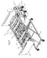
figure 1 est une vue en perspective d'une barrière de lit comprenant deux panneaux, dans une position pliée ; - la
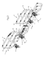
figure 2 est une vue en perspective de la barrière de lafigure 1 dans une position déployée ; - la
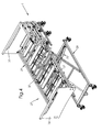
figure 3 est une vue en perspective d'un lit, notamment un lit médical et de la barrière de lafigure 1 , dans une première position d'assemblage ; - la
figure 4 est une vue similaire à celle de lafigure 3 , le lit et la barrière étant dans une deuxième position d'assemblage ; - la
figure 5 est une vue similaire à celle de lafigure 4 , le lit et la barrière étant dans une troisième position d'assemblage ; - la
figure 6 est une vue similaire à celle de lafigure 5 , le lit et la barrière étant dans une quatrième, et dernière position d'assemblage ; - la
figure 7 est une vue similaire à celle de lafigure 6 , la barrière comprenant un panneau dans une position escamotée ; - la
figure 8 est une vue similaire à celle de lafigure 7 , dans laquelle l'autre panneau est dans une position escamotée ; - la
figure 9 est une vue similaire à celle desfigures 7 et8 , dans laquelle les deux panneaux sont dans une position escamotée.
- the
figure 1 is a perspective view of a bed barrier comprising two panels, in a folded position; - the
figure 2 is a perspective view of the barrier of thefigure 1 in a deployed position; - the
figure 3 is a perspective view of a bed, including a medical bed and the barrier of thefigure 1 in a first assembly position; - the
figure 4 is a view similar to that of thefigure 3 the bed and the barrier being in a second assembly position; - the
figure 5 is a view similar to that of thefigure 4 the bed and the barrier being in a third assembly position; - the
figure 6 is a view similar to that of thefigure 5 , the bed and the barrier being in a fourth, and last assembly position; - the
figure 7 is a view similar to that of thefigure 6 the barrier comprising a panel in a retracted position; - the
figure 8 is a view similar to that of thefigure 7 wherein the other panel is in a retracted position; - the
figure 9 is a view similar to that offigures 7 and8 wherein both panels are in a retracted position.
Sur les
Par panneau, il est désigné un élément garde-corps de la barrière, empêchant un patient du lit de tomber.Per panel, it is designated a guardrail element of the barrier, preventing a patient of the bed from falling.
Ainsi, les panneaux 2, 3 peuvent être des panneaux pleins, des panneaux ajourés, des panneaux en treillis, ou encore des panneaux formés de barreauxThus, the
Le bras 4 de support comprend deux sections 5, 6, appelées section 5 avant et section 6 arrière, distinctes l'une de l'autre. La section 5 avant s'étend à partir d'une première 7 extrémité du bras 4 de support et est prolongée par la section 6 arrière jusqu'à la deuxième 8 extrémité du bras 4 de support. De préférence, comme il sera vu plus loin, la section 5 avant est en liaison pivot avec la section 6 arrière, de sorte que la barrière 1 peut prendre deux positions :
- une position déployée dans laquelle la section 5 avant est sensiblement dans le prolongement de la
section 6 arrière (figure 2 ), et - une position pliée, dans laquelle la section 5 avant est rabattue contre la
section 6 arrière (figure 1 ).
- an extended position in which the front section 5 is substantially in the extension of the rear section 6 (
figure 2 ), and - a folded position, in which the front section is folded against the rear section 6 (
figure 1 ).
De préférence, en position déployée, la section 5 avant est aboutée à la section 6 arrière.Preferably, in the deployed position, the front section 5 abuts the
Selon le mode de réalisation préféré, le bras 4 de support comprend une entretoise 9 reliant la section 5 avant et la section 6 arrière. Plus précisément, la section 5 avant est montée pivotante sur une première portion 10 extrême de l'entretoise 9 par rapport à un premier axe et la section 6 arrière est montée pivotante sur la deuxième portion 11 extrême de l'entretoise 9 par rapport à un deuxième axe parallèle au premier axe.According to the preferred embodiment, the support arm 4 comprises a
L'entretoise 9 permet ainsi, lorsque la barrière 1 est en position déployée, de conserver les deux sections 5, 6 à une même hauteur par rapport à leurs axes de rotation sur l'entretoise 9. En outre, en position pliée, les deux sections 5, 6 peuvent être sensiblement parallèles l'une à l'autre, malgré la présence des panneaux 2, 3 portés par les sections 5, 6.The
Le panneau 2 avant est en liaison avec la section 5 avant du bras 4 de support tandis que le panneau 3 arrière est en liaison avec la section 6 arrière du bras 4 de support.The front panel 2 is in connection with the front section 5 of the support arm 4 while the
L'expression « en liaison avec » désigne ici la caractéristique selon laquelle il existe au moins une liaison entre deux corps, en l'occurrence entre un panneau 2, 3 et une section 5, 6.The term "connected with" here refers to the characteristic that there is at least one bond between two bodies, in this case between a
Plus précisément, selon un mode de réalisation préféré, le panneau 2 avant comprend une première liaison 12 sur la section 5 avant et le panneau 3 arrière comprend une deuxième liaison 13 et une troisième liaison 14 sur la section 6 arrière, la troisième liaison 14 étant plus proche de la deuxième extrémité 8 du bras 4 de support que la deuxième liaison 13. Le nombre de liaisons de chaque panneau 2, 3 sur une section 5, 6 du bras 4 de support pourra cependant être adapté selon les besoins de conception.More specifically, according to a preferred embodiment, the front panel 2 comprises a
De part le fait que chaque panneau 2, 3 est en liaison avec une section 5, 6 distincte du bras 4 de support, la liaison du panneau 2 avant sur la section 5 avant du bras 4 de support est écartée de la liaison du panneau 3 arrière sur la section 6 arrière du bras 4 de support, c'est-à-dire qu'une distance déterminée lors de la conception de la barrière 1 peut être mesurée entre chaque liaison du panneau 2 avant sur le bras 4 de support et chaque liaison du panneau 3 arrière sur le bras 4 de support, mesurée le long du bras 4 de support lorsque la barrière 1 est en position déployée.Due to the fact that each
Par exemple, selon un mode de réalisation préféré, lorsque la barrière 1 est en position déployée, les deux panneaux 2, 3 ne sont pas en contact l'un avec l'autre, et un écartement selon la direction du bras 4 de support en position déployée peut être mesuré, correspondant à la distance entre la première liaison 12 et la deuxième liaison 13.For example, according to a preferred embodiment, when the
La barrière 1 comprend en outre des moyens 15 de fixation sur un longeron 37 du lit, portés par le bras 4 de support. Selon un mode de réalisation préféré, les moyens 15 de fixation sont solidaires du bras 4 de support, et les panneaux 2, 3 sont en liaison avec les moyens 15 de fixation. Avantageusement, les moyens 15 de fixation sont des moyens amovibles, c'est-à-dire qu'ils peuvent être aisément démontés et assemblés sur le lit, de préférence sans outils.The
Par exemple, les moyens 15 de fixation se présentent sous la forme de mâchoires 16 ajustables au moyen d'une poignée 17 pouvant être actionnée manuellement. Le blocage de la barrière 1 sur le lit peut ainsi être obtenu par serrage des mâchoires 16. Le montage de la barrière 1 sur le lit sera décrit avec plus de précision plus loin.For example, the fixing means 15 are in the form of
Plus précisément, chaque panneau 2, 3 se présente par exemple sous la forme d'un élément sensiblement plan, c'est-à-dire qu'il présente des dimensions plus importantes dans deux directions que celles dans la troisième direction. Il peut ainsi par exemple être un panneau plein, ou un treillis.More specifically, each
Selon un mode de réalisation préféré, chaque panneau 2, 3 comprend deux montants 18 reliés par au moins un barreau 19. En pratique, les montants 18 sont reliés par une série de barreaux 19 parallèles, par exemple trois barreaux 19.According to a preferred embodiment, each
Pour la suite de la description, il est défini pour chaque panneau 2, 3 une direction Z verticale et une direction X longitudinale, comprises dans le plan du panneau, et une direction Y transversale, perpendiculaire au plan du panneau 2, 3. A des fins de simplification On notera :
- X2, Y2 et Z2 les directions définies sur le panneau 2 avant,
- X3, Y3 et Z3 les directions définies sur le panneau 3 arrière.
- X2, Y2 and Z2 the directions defined on the front panel 2,
- X3, Y3 and Z3 the directions defined on the
rear panel 3.
Chaque montant 18 se présente sous la forme d'un tube cintré, comprenant une portion 20 droite. Le panneau 2 avant comprend un montant 18 dont une portion 21 extrême inférieure est montée pivotante sur la section 5 avant du bras 4 de support autour d'un axe parallèle à la direction Y2 transversale du panneau 2 avant pour former la première liaison 12 tandis que les deux montants 18 du panneau 3 arrière présentent une portion 21 extrême inférieure, toutes les deux montées pivotantes sur la section 6 arrière du bras 4 de support autour d'axes parallèles à la direction Y3 transversale du panneau 3 arrière pour former respectivement la deuxième liaison 13 et la troisième liaison 14.Each
Plus précisément, selon un mode de réalisation, chaque liaison 12, 13, 14 est portée par une mâchoire 16 solidaire du bras 4 de support, deux mâchoires 16 étant fixées sur la section 6 arrière et une mâchoire 16 étant fixée sur la section 5 avant. Cependant, une seule mâchoire 16 fixée sur la section 6 arrière pourra suffire, de sorte qu'une liaison, par exemple la troisième liaison 14, du panneau 3 arrière sur le bras est alors directement réalisée sur la section 6 arrière du bras 4.More specifically, according to one embodiment, each
Les deux montants 18 du panneau 3 arrière sont alors montés respectivement sur une des mâchoires 16 de la section 6 arrière, pivotant chacun autour d'un axe parallèle à la direction Y3 transversale du panneau 3 arrière, pour former la deuxième liaison 13 et la troisième liaison 14.The two
Un seul montant 18 du panneau 2 avant est monté sur la mâchoire 16 de la section 5 avant, pivotant autour d'un axe parallèle à la direction Y2 transversale, pour former la première liaison 12. De préférence, la portion 21 extrême inférieure du deuxième montant 18 du panneau 2 avant est également montée sur une quatrième mâchoire 16, laquelle peut toutefois ne pas être solidaire du bras 4 de support.A
Les liaisons 12, 13, 14 des panneaux 2, 3 sur le bras 4 de support sont représentées en
L'écartement entre la première liaison 12 et la deuxième liaison 13 pourra avantageusement être déterminé de sorte que les panneaux 2, 3 ne se chevauchent pas et que le montant 18 du panneau 2 avant monté sur la première liaison 12 soit à distance du montant 18 du panneau 3 arrière adjacent, monté sur la deuxième liaison 13.The spacing between the
De plus, pour chaque panneau 2, 3, le barreau 19 reliant les deux montants 18 doit avantageusement être sensiblement parallèle à la direction X2, X3 longitudinale. De même, pour chaque panneau 2, 3, les mâchoires 16 doivent être alignées selon la direction X2, X3 longitudinale. Enfin, pour chaque panneau 2, 3, les portions 20 droites des deux montants 18 de chaque panneau 2, 3 sont disposées de manière à être sensiblement parallèles entre elles.In addition, for each
Ainsi, chaque panneau 2, 3 est déformable par rotation des montants 18 sur les barreaux 19 et sur les mâchoires 16, selon un parallélogramme déformable formé d'une part par les deux montants 18 et d'autre part par les barreaux 19 et l'alignement des mâchoires 16, entre deux positions :
- une position relevée, dans laquelle la
portion 20 droite des montants 18 est sensiblement perpendiculaire aux barreaux 19 (en traits pleins sur lafigure 2 ), c'est-à-dire sensiblement parallèle à la direction Z2, Z3 verticale ; - une position escamotée, dans laquelle la
portion 20 droite des montants 18 est sensiblement parallèle aux barreaux 19 (en traits discontinus sur lafigure 2 ), c'est-à-dire sensiblement parallèle à la direction X2, X3 longitudinale.
- a raised position, in which the right portion of the
uprights 18 is substantially perpendicular to the bars 19 (in solid lines on thefigure 2 ), that is to say substantially parallel to the vertical direction Z2, Z3; - a retracted position, in which the right portion of the
uprights 18 is substantially parallel to the bars 19 (in broken lines on thefigure 2 ), that is to say substantially parallel to the longitudinal direction X2, X3.
De par l'indépendance de la liaison du panneau 2 avant sur le bras 4 de support par rapport à la liaison du panneau 3 arrière sur le bras 4 de support, chacun des deux panneaux 2, 3 peut être manipulé pour être mis dans la position relevée ou dans la position escamotée sans que la position de l'autre panneau n'en soit influencée.Due to the independence of the connection of the front panel 2 on the support arm 4 with respect to the connection of the
Avantageusement, la barrière 1 comprend des moyens 22 pour bloquer chaque panneau 2, 3 en position relevée. A cet effet pour chaque panneau 2, 3, un des montants 18 comprend une languette 23 munie d'une ouverture 24 et la mâchoire 16 correspondante, c'est-à-dire la mâchoire 16 sur laquelle est monté le montant 18 considéré, comprend également une ouverture 25, par exemple taraudée. Lorsque le panneau 2, 3 est en position relevée, les deux ouvertures 24, 25 sont mises en coïncidence, et un doigt 26 d'indexage est inséré dans les deux ouvertures 24, 25. Le doigt 26 peut comprendre une portion filetée, coopérant avec le taraudage de l'ouverture 24 sur la mâchoire 16 pour bloquer le doigt 26.Advantageously, the
Il est maintenant décrit le montage de la barrière 1 selon le mode de réalisation préféré sur un lit 27, notamment un lit médical, en référence aux
Le lit 27 comprend un cadre 28 inférieur, qui peut être monté sur roulettes, et un cadre 29 supérieur portant un sommier 30 pour définir une surface 31 de couchage. Des moyens 32 pour régler la hauteur du sommier 30 par rapport au cadre 28 inférieur, par exemple un système à croisillons, peuvent être interposés entre le cadre 28 inférieur et le cadre 29 supérieur.The
Le lit 27 présente une région 33 de tête, correspondant à la portion du sommier 30 destinée à supporter notamment la tête et le torse d'un patient, et une région 34 de pieds, correspondant à la portion du sommier 30 destinée à supporter notamment les jambes et les pieds du patient. Des moyens pour soulever la portion de tête du sommier 30 par rapport à la portion de pieds, et inversement, peuvent être prévus sur le lit 27.The
Le lit 27 peut également comprendre un panneau 35 de tête et un panneau 36 de pieds.
Le cadre 29 supérieur comprend notamment deux longerons 37 s'étendant de chaque côté du lit 27, sur sa longueur, par exemple entre le panneau 35 de tête et le panneau 36 de pieds.The
La barrière 1 est amenée sur le lieu du montage en position pliée (
Les mâchoires 16 du panneau 2 avant sont alors posées sur le longeron 37, de manière à pouvoir positionner la barrière 1 par glissement le long du longeron 37. Il est alors possible par exemple de mettre le panneau 2 avant en butée contre le panneau 35 de tête. Les mâchoires 16 sont ensuite serrées au moyen des poignées 17, pour bloquer la section 5 avant du bras 4 de support sur le longeron 37 (
Ainsi, la mâchoire 16 portée par le panneau 2 avant qui n'est pas solidaire du bras 4 de support est la mâchoire placée au plus près du panneau 35 de tête. Une telle disposition permet avantageusement, lorsque la barrière 1 est assemblée sur le longeron 37, de laisser libre la portion de longeron 37 immédiatement à proximité du panneau 35 de tête, correspondant à la portion de longeron qui bordera la tête du patient allongé sur le lit. D'autres équipements nécessaires aux soins du patient pourront alors être disposés à proximité de la tête et du buste du patient.Thus, the
A ce stade, la barrière 1 est déjà positionnée sur le longeron 37 du lit 27. La section 6 arrière du bras 4 de support peut toutefois encore pivoter par rapport à la section 5 avant bloquée (
La barrière 1 est alors mise en position déployée, de manière à ce que le bras 4 de support soit sensiblement parallèle au longeron 37 et que les mâchoires 16 du panneau 3 arrière puissent être posées puis serrées sur le longeron 37 du lit 27 (
La rotation des sections 5, 6 du bras 4 de support l'une par rapport à l'autre permet ainsi de fixer les mâchoires 16 deux à deux, au lieu d'avoir à fixer les quatre ne même temps, de sorte que l'assemblage est facilité.The rotation of the
En variante, les mâchoires 16 peuvent être solidaires du longeron, et le bras 4 de support est rapporté sur les mâchoires pour le blocage. Des moyens d'indexage des mâchoires 16 sur le bras 4 de support pourront être prévus à cet effet.Alternatively, the
La barrière 1 ainsi assemblée sur le lit 27 peut être démontée aisément, simplement en desserrant les mâchoires 16, puis rangée et stockée en position pliée.The
En outre, un écartement fixe entre les deux panneaux 2, 3 peut être déterminé, donné par la position des liaisons 12, 13, 14 du panneau 2 avant et du panneau 3 arrière sur le 4 bras de support, afin de répondre aux exigences de sécurité. Ainsi, un opérateur assemblant la barrière 1 sur le lit 27 n'a-t-il pas besoin de déterminer lui-même cette distance, au risque d'aller à l'encontre des normes.In addition, a fixed spacing between the two
La position escamotée des panneaux 2, 3 permet de les rabattre au plus près du longeron 37, de manière à libérer les côtés de la surface 31 de couchage et faciliter à la fois l'accès au patient par le personnel et la sortie du patient du lit.The retracted position of the
Au contraire, en position relevée, les panneaux 2, 3 s'étendent au-dessus du longeron 37, bordant la surface 31 de couchage, pour éviter au patient de chuter.On the contrary, in the raised position, the
Comme indiqué précédemment, chaque panneau 2, 3 est indépendant de l'autre. En effet, il est par exemple possible de mettre le panneau 2 avant en position relevée et le panneau 3 arrière en position escamotée, par exemple pour laisser le patient sortir seul du lit 27 (
La position de la barrière 1 sur le longeron 37 est par exemple déterminée par la longueur du bras 4 de support en position déployée. En effet, la longueur des lits peut être standardisée, de sorte que pour une longueur donnée du bras 4 de support en position déployée, la butée du panneau 2 avant contre le panneau 35 de tête fixe les autres distances de la barrière 1 par rapport aux panneaux du lit 27 pour répondre aux exigences de sécurité.The position of the
De la même manière, une deuxième barrière 1 pourra être assemblée sur le deuxième longeron 37 du lit 27, de manière à encadrer de part et d'autre la surface 31 de couchage par les panneaux 2, 3 en position relevée.In the same way, a
La barrière 1 ainsi formée permet d'offrir les avantages des demi-barrières, tout en évitant les inconvénients de montage et de démontage.The
En effet, en offrant un écartement prédéterminé entre les panneaux 2, 3, un opérateur n'a pas besoin de mesurer lui-même la position des panneaux 2, 3 pour répondre aux exigences de sécurité et aux normes.Indeed, by providing a predetermined spacing between the
La barrière 1 peut aisément être montée sur le lit 27, à la manière d'un accessoire, c'est-à-dire sans influer sur la conception du lit 27. Le lit 27 peut alors être fabriqué en série, de manière à réduire les coûts de fabrication, et la barrière 1 n'y être montée qu'en cas de besoin.The
En outre, en position pliée, la barrière 1 présente un encombrement minimum, de sorte qu'elle peut être facilement transportée et stockée.In addition, in the folded position, the
L'utilisation de mâchoires 16 comme moyens 15 de fixation permet un assemblage rapide, sans outils, diminuant les efforts de l'opérateur.The use of
Claims (10)
Applications Claiming Priority (1)
| Application Number | Priority Date | Filing Date | Title |
|---|---|---|---|
| FR1157978A FR2979818B1 (en) | 2011-09-08 | 2011-09-08 | BED BARRIER, IN PARTICULAR A MEDICAL BED, AND METHOD OF MOUNTING SUCH A BARRIER |
Publications (3)
| Publication Number | Publication Date |
|---|---|
| EP2567686A2 true EP2567686A2 (en) | 2013-03-13 |
| EP2567686A3 EP2567686A3 (en) | 2014-10-08 |
| EP2567686B1 EP2567686B1 (en) | 2017-06-14 |
Family
ID=46762986
Family Applications (1)
| Application Number | Title | Priority Date | Filing Date |
|---|---|---|---|
| EP12183617.5A Active EP2567686B1 (en) | 2011-09-08 | 2012-09-07 | Bed rail, especially of a medical bed, and method for mounting such a rail |
Country Status (2)
| Country | Link |
|---|---|
| EP (1) | EP2567686B1 (en) |
| FR (1) | FR2979818B1 (en) |
Cited By (3)
| Publication number | Priority date | Publication date | Assignee | Title |
|---|---|---|---|---|
| GB2542875A (en) * | 2016-04-18 | 2017-04-05 | Accora Ltd | Bed frame |
| CN109771153A (en) * | 2019-03-19 | 2019-05-21 | 田雪莲 | A kind of emergency department's patient transfer hospital bed |
| EP3964186A1 (en) * | 2020-09-08 | 2022-03-09 | Hermann Bock GmbH | Side rail for a bed |
Families Citing this family (1)
| Publication number | Priority date | Publication date | Assignee | Title |
|---|---|---|---|---|
| FR3067927B1 (en) | 2017-06-26 | 2019-08-16 | Winncare France | TELESCOPIC AMOUNT OF BED BARRIER AND MEDICAL BED COMPRISING SUCH A BARRIER |
Citations (4)
| Publication number | Priority date | Publication date | Assignee | Title |
|---|---|---|---|---|
| DE202004017406U1 (en) | 2004-11-09 | 2005-01-27 | Hermann Bock Gmbh | Hospital bed, comprising railing to be swiveled around element positioned under frame and to be stored underneath when not in use |
| US20060195984A1 (en) | 2005-03-07 | 2006-09-07 | Reza Hakamiun | Siderail for a hospital bed |
| US20080127415A1 (en) | 2004-03-12 | 2008-06-05 | Ruschke Jeffrey A | Variable Height Siderail for a Bed |
| EP1970038A1 (en) | 2007-03-13 | 2008-09-17 | Schell Industries | Bed with compact collapsible security barrier |
Family Cites Families (5)
| Publication number | Priority date | Publication date | Assignee | Title |
|---|---|---|---|---|
| US354880A (en) * | 1886-12-28 | Safety attachment for scaffolds | ||
| US3248744A (en) * | 1964-12-14 | 1966-05-03 | Clyde B Hutt | Folding side guard attachment for hospital bed |
| US6389622B1 (en) * | 2000-08-03 | 2002-05-21 | Chiou-Feng Her | Hospital bed |
| TWM334708U (en) * | 2007-07-03 | 2008-06-21 | Optima Healthcare Inc | Handrail mechanism of bed frame |
| FR2934774B1 (en) * | 2008-08-05 | 2010-09-17 | Hill Rom Sas | BED OF SICK WITH BARRIERS. |
-
2011
- 2011-09-08 FR FR1157978A patent/FR2979818B1/en active Active
-
2012
- 2012-09-07 EP EP12183617.5A patent/EP2567686B1/en active Active
Patent Citations (4)
| Publication number | Priority date | Publication date | Assignee | Title |
|---|---|---|---|---|
| US20080127415A1 (en) | 2004-03-12 | 2008-06-05 | Ruschke Jeffrey A | Variable Height Siderail for a Bed |
| DE202004017406U1 (en) | 2004-11-09 | 2005-01-27 | Hermann Bock Gmbh | Hospital bed, comprising railing to be swiveled around element positioned under frame and to be stored underneath when not in use |
| US20060195984A1 (en) | 2005-03-07 | 2006-09-07 | Reza Hakamiun | Siderail for a hospital bed |
| EP1970038A1 (en) | 2007-03-13 | 2008-09-17 | Schell Industries | Bed with compact collapsible security barrier |
Cited By (4)
| Publication number | Priority date | Publication date | Assignee | Title |
|---|---|---|---|---|
| GB2542875A (en) * | 2016-04-18 | 2017-04-05 | Accora Ltd | Bed frame |
| GB2542875B (en) * | 2016-04-18 | 2017-10-25 | Accora Ltd | Bed frame |
| CN109771153A (en) * | 2019-03-19 | 2019-05-21 | 田雪莲 | A kind of emergency department's patient transfer hospital bed |
| EP3964186A1 (en) * | 2020-09-08 | 2022-03-09 | Hermann Bock GmbH | Side rail for a bed |
Also Published As
| Publication number | Publication date |
|---|---|
| FR2979818B1 (en) | 2017-01-06 |
| FR2979818A1 (en) | 2013-03-15 |
| EP2567686B1 (en) | 2017-06-14 |
| EP2567686A3 (en) | 2014-10-08 |
Similar Documents
| Publication | Publication Date | Title |
|---|---|---|
| EP2567686B1 (en) | Bed rail, especially of a medical bed, and method for mounting such a rail | |
| EP0900037A1 (en) | Chair consisting of interlocking elements | |
| EP2116217B1 (en) | Bed with foldable bed base | |
| EP1721550B1 (en) | Patient bed with a complete side rail | |
| WO2009156660A2 (en) | Improvement to screens for protection against ionising radiation emissions | |
| FR2908804A1 (en) | Fixed or rolling scaffolding guardrail, has operating handle articulated towards end of guardrail opposite to hook, where horizontal distance provided between inner edge of hooks is greater than distance between exterior of rod and post | |
| EP2216464B1 (en) | Modular platform | |
| FR2937359A1 (en) | SOLIDARY SCALE AND SUBLIND ASSEMBLY FOR SCAFFOLDING, METHOD OF MOUNTING AND SCAFFOLDING OBTAINED | |
| FR2794643A1 (en) | Folding chair for carrying a disabled person e.g. in emergency situation has seat and back frames and hinged front and rear supports | |
| FR3012511A1 (en) | SCALE EQUIPPED WITH A TWO-PART DISABLED STABILIZER | |
| FR2990847A1 (en) | Ambulatory stretcher for supporting patient in hospital, has hanger including two portions slidably mounted in two tubes of body of barrier, respectively, where length of barrier is regulated by displacement of hanger compared to body | |
| FR2789302A1 (en) | Modular gurney for transporting patients has rigid tube sections with honeycomb panels between assembled to form gurney | |
| FR3073734B1 (en) | COMPACT BED CONFIGURE TO ADOPT A CONFIGURATION TROLLEY FACILITATING ITS TRANSPORT | |
| FR2817720A1 (en) | MULTI-POSITION ARMCHAIR | |
| FR2711522A1 (en) | Invalid bed with safety barrier | |
| FR2698327A1 (en) | Automatic folding mechanism for seats or benches e.g. for use in motor vehicles - includes two rear feet extending from seatback frame, each foot secured to vehicle floor by release mechanisms and also hinged to seat frame, with links hingeably connecting seat frame front region to floor | |
| EP2695591B1 (en) | Hospital bed with easy installation and method for installing such a bed | |
| EP0580456B1 (en) | Scaffolding | |
| EP3806803B1 (en) | Means for transporting persons with reduced mobility comprising a device for connecting to an iv pole, associated connection assembly | |
| FR2947849A1 (en) | Support leg for e.g. rapid scaffold, in building site, has blocking system occupying sliding position in which teeth are at distance from tubes and blocking position in which teeth are supported against one tube | |
| FR2928384A1 (en) | Protection barrier forming assembly for protecting person crossing railway track, has rails and support that are compatible with imposed clearance for passage of train on track or adjacent track, in lying position | |
| EP2835126B1 (en) | Locomotion assistance device | |
| FR2873916A1 (en) | Knee-joint supporting and mobilizing device for surgical operation of knee, has rod mounted free in rotation along horizontal plate and rotated around its axis by rod driving mechanism activatable to incline footplates so as to bend thigh | |
| FR2891444A1 (en) | Combined body support and tray, e.g. for handicapped person, has tray designed to fold or move away for easier access | |
| FR3111563A1 (en) | TROLLEY FOR BLOOD TAKING OR INJECTION |
Legal Events
| Date | Code | Title | Description |
|---|---|---|---|
| PUAI | Public reference made under article 153(3) epc to a published international application that has entered the european phase |
Free format text: ORIGINAL CODE: 0009012 |
|
| AK | Designated contracting states |
Kind code of ref document: A2 Designated state(s): AL AT BE BG CH CY CZ DE DK EE ES FI FR GB GR HR HU IE IS IT LI LT LU LV MC MK MT NL NO PL PT RO RS SE SI SK SM TR |
|
| AX | Request for extension of the european patent |
Extension state: BA ME |
|
| RIC1 | Information provided on ipc code assigned before grant |
Ipc: A61G 7/05 20060101AFI20140429BHEP Ipc: A61G 7/012 20060101ALN20140429BHEP |
|
| PUAL | Search report despatched |
Free format text: ORIGINAL CODE: 0009013 |
|
| AK | Designated contracting states |
Kind code of ref document: A3 Designated state(s): AL AT BE BG CH CY CZ DE DK EE ES FI FR GB GR HR HU IE IS IT LI LT LU LV MC MK MT NL NO PL PT RO RS SE SI SK SM TR |
|
| AX | Request for extension of the european patent |
Extension state: BA ME |
|
| RIC1 | Information provided on ipc code assigned before grant |
Ipc: A61G 7/05 20060101AFI20140904BHEP Ipc: A61G 7/012 20060101ALN20140904BHEP |
|
| 17P | Request for examination filed |
Effective date: 20141203 |
|
| RBV | Designated contracting states (corrected) |
Designated state(s): AL AT BE BG CH CY CZ DE DK EE ES FI FR GB GR HR HU IE IS IT LI LT LU LV MC MK MT NL NO PL PT RO RS SE SI SK SM TR |
|
| RIC1 | Information provided on ipc code assigned before grant |
Ipc: A61G 7/05 20060101AFI20161116BHEP Ipc: A61G 7/012 20060101ALN20161116BHEP |
|
| GRAP | Despatch of communication of intention to grant a patent |
Free format text: ORIGINAL CODE: EPIDOSNIGR1 |
|
| RAP1 | Party data changed (applicant data changed or rights of an application transferred) |
Owner name: MEDICATLANTIC |
|
| INTG | Intention to grant announced |
Effective date: 20170213 |
|
| GRAS | Grant fee paid |
Free format text: ORIGINAL CODE: EPIDOSNIGR3 |
|
| GRAA | (expected) grant |
Free format text: ORIGINAL CODE: 0009210 |
|
| AK | Designated contracting states |
Kind code of ref document: B1 Designated state(s): AL AT BE BG CH CY CZ DE DK EE ES FI FR GB GR HR HU IE IS IT LI LT LU LV MC MK MT NL NO PL PT RO RS SE SI SK SM TR |
|
| REG | Reference to a national code |
Ref country code: GB Ref legal event code: FG4D Free format text: NOT ENGLISH |
|
| REG | Reference to a national code |
Ref country code: CH Ref legal event code: EP Ref country code: AT Ref legal event code: REF Ref document number: 900285 Country of ref document: AT Kind code of ref document: T Effective date: 20170615 |
|
| REG | Reference to a national code |
Ref country code: IE Ref legal event code: FG4D Free format text: LANGUAGE OF EP DOCUMENT: FRENCH |
|
| REG | Reference to a national code |
Ref country code: DE Ref legal event code: R096 Ref document number: 602012033377 Country of ref document: DE |
|
| REG | Reference to a national code |
Ref country code: FR Ref legal event code: PLFP Year of fee payment: 6 |
|
| REG | Reference to a national code |
Ref country code: NL Ref legal event code: MP Effective date: 20170614 |
|
| REG | Reference to a national code |
Ref country code: LT Ref legal event code: MG4D |
|
| PG25 | Lapsed in a contracting state [announced via postgrant information from national office to epo] |
Ref country code: NO Free format text: LAPSE BECAUSE OF FAILURE TO SUBMIT A TRANSLATION OF THE DESCRIPTION OR TO PAY THE FEE WITHIN THE PRESCRIBED TIME-LIMIT Effective date: 20170914 Ref country code: GR Free format text: LAPSE BECAUSE OF FAILURE TO SUBMIT A TRANSLATION OF THE DESCRIPTION OR TO PAY THE FEE WITHIN THE PRESCRIBED TIME-LIMIT Effective date: 20170915 Ref country code: LT Free format text: LAPSE BECAUSE OF FAILURE TO SUBMIT A TRANSLATION OF THE DESCRIPTION OR TO PAY THE FEE WITHIN THE PRESCRIBED TIME-LIMIT Effective date: 20170614 Ref country code: ES Free format text: LAPSE BECAUSE OF FAILURE TO SUBMIT A TRANSLATION OF THE DESCRIPTION OR TO PAY THE FEE WITHIN THE PRESCRIBED TIME-LIMIT Effective date: 20170614 Ref country code: HR Free format text: LAPSE BECAUSE OF FAILURE TO SUBMIT A TRANSLATION OF THE DESCRIPTION OR TO PAY THE FEE WITHIN THE PRESCRIBED TIME-LIMIT Effective date: 20170614 Ref country code: FI Free format text: LAPSE BECAUSE OF FAILURE TO SUBMIT A TRANSLATION OF THE DESCRIPTION OR TO PAY THE FEE WITHIN THE PRESCRIBED TIME-LIMIT Effective date: 20170614 |
|
| REG | Reference to a national code |
Ref country code: AT Ref legal event code: MK05 Ref document number: 900285 Country of ref document: AT Kind code of ref document: T Effective date: 20170614 |
|
| PG25 | Lapsed in a contracting state [announced via postgrant information from national office to epo] |
Ref country code: RS Free format text: LAPSE BECAUSE OF FAILURE TO SUBMIT A TRANSLATION OF THE DESCRIPTION OR TO PAY THE FEE WITHIN THE PRESCRIBED TIME-LIMIT Effective date: 20170614 Ref country code: LV Free format text: LAPSE BECAUSE OF FAILURE TO SUBMIT A TRANSLATION OF THE DESCRIPTION OR TO PAY THE FEE WITHIN THE PRESCRIBED TIME-LIMIT Effective date: 20170614 Ref country code: SE Free format text: LAPSE BECAUSE OF FAILURE TO SUBMIT A TRANSLATION OF THE DESCRIPTION OR TO PAY THE FEE WITHIN THE PRESCRIBED TIME-LIMIT Effective date: 20170614 Ref country code: NL Free format text: LAPSE BECAUSE OF FAILURE TO SUBMIT A TRANSLATION OF THE DESCRIPTION OR TO PAY THE FEE WITHIN THE PRESCRIBED TIME-LIMIT Effective date: 20170614 Ref country code: BG Free format text: LAPSE BECAUSE OF FAILURE TO SUBMIT A TRANSLATION OF THE DESCRIPTION OR TO PAY THE FEE WITHIN THE PRESCRIBED TIME-LIMIT Effective date: 20170914 |
|
| PG25 | Lapsed in a contracting state [announced via postgrant information from national office to epo] |
Ref country code: CZ Free format text: LAPSE BECAUSE OF FAILURE TO SUBMIT A TRANSLATION OF THE DESCRIPTION OR TO PAY THE FEE WITHIN THE PRESCRIBED TIME-LIMIT Effective date: 20170614 Ref country code: RO Free format text: LAPSE BECAUSE OF FAILURE TO SUBMIT A TRANSLATION OF THE DESCRIPTION OR TO PAY THE FEE WITHIN THE PRESCRIBED TIME-LIMIT Effective date: 20170614 Ref country code: AT Free format text: LAPSE BECAUSE OF FAILURE TO SUBMIT A TRANSLATION OF THE DESCRIPTION OR TO PAY THE FEE WITHIN THE PRESCRIBED TIME-LIMIT Effective date: 20170614 Ref country code: SK Free format text: LAPSE BECAUSE OF FAILURE TO SUBMIT A TRANSLATION OF THE DESCRIPTION OR TO PAY THE FEE WITHIN THE PRESCRIBED TIME-LIMIT Effective date: 20170614 Ref country code: EE Free format text: LAPSE BECAUSE OF FAILURE TO SUBMIT A TRANSLATION OF THE DESCRIPTION OR TO PAY THE FEE WITHIN THE PRESCRIBED TIME-LIMIT Effective date: 20170614 |
|
| PG25 | Lapsed in a contracting state [announced via postgrant information from national office to epo] |
Ref country code: SM Free format text: LAPSE BECAUSE OF FAILURE TO SUBMIT A TRANSLATION OF THE DESCRIPTION OR TO PAY THE FEE WITHIN THE PRESCRIBED TIME-LIMIT Effective date: 20170614 Ref country code: IT Free format text: LAPSE BECAUSE OF FAILURE TO SUBMIT A TRANSLATION OF THE DESCRIPTION OR TO PAY THE FEE WITHIN THE PRESCRIBED TIME-LIMIT Effective date: 20170614 Ref country code: IS Free format text: LAPSE BECAUSE OF FAILURE TO SUBMIT A TRANSLATION OF THE DESCRIPTION OR TO PAY THE FEE WITHIN THE PRESCRIBED TIME-LIMIT Effective date: 20171014 Ref country code: PL Free format text: LAPSE BECAUSE OF FAILURE TO SUBMIT A TRANSLATION OF THE DESCRIPTION OR TO PAY THE FEE WITHIN THE PRESCRIBED TIME-LIMIT Effective date: 20170614 |
|
| REG | Reference to a national code |
Ref country code: DE Ref legal event code: R097 Ref document number: 602012033377 Country of ref document: DE |
|
| REG | Reference to a national code |
Ref country code: DE Ref legal event code: R119 Ref document number: 602012033377 Country of ref document: DE |
|
| PLBE | No opposition filed within time limit |
Free format text: ORIGINAL CODE: 0009261 |
|
| STAA | Information on the status of an ep patent application or granted ep patent |
Free format text: STATUS: NO OPPOSITION FILED WITHIN TIME LIMIT |
|
| PG25 | Lapsed in a contracting state [announced via postgrant information from national office to epo] |
Ref country code: DK Free format text: LAPSE BECAUSE OF FAILURE TO SUBMIT A TRANSLATION OF THE DESCRIPTION OR TO PAY THE FEE WITHIN THE PRESCRIBED TIME-LIMIT Effective date: 20170614 |
|
| REG | Reference to a national code |
Ref country code: CH Ref legal event code: PL |
|
| 26N | No opposition filed |
Effective date: 20180315 |
|
| GBPC | Gb: european patent ceased through non-payment of renewal fee |
Effective date: 20170914 |
|
| PG25 | Lapsed in a contracting state [announced via postgrant information from national office to epo] |
Ref country code: MC Free format text: LAPSE BECAUSE OF FAILURE TO SUBMIT A TRANSLATION OF THE DESCRIPTION OR TO PAY THE FEE WITHIN THE PRESCRIBED TIME-LIMIT Effective date: 20170614 |
|
| REG | Reference to a national code |
Ref country code: FR Ref legal event code: CD Owner name: WINNCARE FRANCE, FR Effective date: 20180517 |
|
| REG | Reference to a national code |
Ref country code: IE Ref legal event code: MM4A |
|
| REG | Reference to a national code |
Ref country code: BE Ref legal event code: MM Effective date: 20170930 |
|
| PG25 | Lapsed in a contracting state [announced via postgrant information from national office to epo] |
Ref country code: LU Free format text: LAPSE BECAUSE OF NON-PAYMENT OF DUE FEES Effective date: 20170907 |
|
| PG25 | Lapsed in a contracting state [announced via postgrant information from national office to epo] |
Ref country code: LI Free format text: LAPSE BECAUSE OF NON-PAYMENT OF DUE FEES Effective date: 20170930 Ref country code: CH Free format text: LAPSE BECAUSE OF NON-PAYMENT OF DUE FEES Effective date: 20170930 Ref country code: IE Free format text: LAPSE BECAUSE OF NON-PAYMENT OF DUE FEES Effective date: 20170907 Ref country code: DE Free format text: LAPSE BECAUSE OF NON-PAYMENT OF DUE FEES Effective date: 20180404 Ref country code: GB Free format text: LAPSE BECAUSE OF NON-PAYMENT OF DUE FEES Effective date: 20170914 |
|
| PG25 | Lapsed in a contracting state [announced via postgrant information from national office to epo] |
Ref country code: SI Free format text: LAPSE BECAUSE OF FAILURE TO SUBMIT A TRANSLATION OF THE DESCRIPTION OR TO PAY THE FEE WITHIN THE PRESCRIBED TIME-LIMIT Effective date: 20170614 Ref country code: BE Free format text: LAPSE BECAUSE OF NON-PAYMENT OF DUE FEES Effective date: 20170930 |
|
| REG | Reference to a national code |
Ref country code: FR Ref legal event code: PLFP Year of fee payment: 7 |
|
| PG25 | Lapsed in a contracting state [announced via postgrant information from national office to epo] |
Ref country code: MT Free format text: LAPSE BECAUSE OF FAILURE TO SUBMIT A TRANSLATION OF THE DESCRIPTION OR TO PAY THE FEE WITHIN THE PRESCRIBED TIME-LIMIT Effective date: 20170614 |
|
| PG25 | Lapsed in a contracting state [announced via postgrant information from national office to epo] |
Ref country code: HU Free format text: LAPSE BECAUSE OF FAILURE TO SUBMIT A TRANSLATION OF THE DESCRIPTION OR TO PAY THE FEE WITHIN THE PRESCRIBED TIME-LIMIT; INVALID AB INITIO Effective date: 20120907 |
|
| PG25 | Lapsed in a contracting state [announced via postgrant information from national office to epo] |
Ref country code: CY Free format text: LAPSE BECAUSE OF NON-PAYMENT OF DUE FEES Effective date: 20170614 |
|
| PG25 | Lapsed in a contracting state [announced via postgrant information from national office to epo] |
Ref country code: MK Free format text: LAPSE BECAUSE OF FAILURE TO SUBMIT A TRANSLATION OF THE DESCRIPTION OR TO PAY THE FEE WITHIN THE PRESCRIBED TIME-LIMIT Effective date: 20170614 |
|
| PG25 | Lapsed in a contracting state [announced via postgrant information from national office to epo] |
Ref country code: TR Free format text: LAPSE BECAUSE OF FAILURE TO SUBMIT A TRANSLATION OF THE DESCRIPTION OR TO PAY THE FEE WITHIN THE PRESCRIBED TIME-LIMIT Effective date: 20170614 |
|
| PG25 | Lapsed in a contracting state [announced via postgrant information from national office to epo] |
Ref country code: PT Free format text: LAPSE BECAUSE OF FAILURE TO SUBMIT A TRANSLATION OF THE DESCRIPTION OR TO PAY THE FEE WITHIN THE PRESCRIBED TIME-LIMIT Effective date: 20170614 |
|
| PG25 | Lapsed in a contracting state [announced via postgrant information from national office to epo] |
Ref country code: AL Free format text: LAPSE BECAUSE OF FAILURE TO SUBMIT A TRANSLATION OF THE DESCRIPTION OR TO PAY THE FEE WITHIN THE PRESCRIBED TIME-LIMIT Effective date: 20170614 |
|
| PGFP | Annual fee paid to national office [announced via postgrant information from national office to epo] |
Ref country code: FR Payment date: 20230915 Year of fee payment: 12 |