EP2567395B1 - Système et procédé permettant d'extraire un échantillon d'une surface - Google Patents
Système et procédé permettant d'extraire un échantillon d'une surface Download PDFInfo
- Publication number
- EP2567395B1 EP2567395B1 EP11778447.0A EP11778447A EP2567395B1 EP 2567395 B1 EP2567395 B1 EP 2567395B1 EP 11778447 A EP11778447 A EP 11778447A EP 2567395 B1 EP2567395 B1 EP 2567395B1
- Authority
- EP
- European Patent Office
- Prior art keywords
- sample
- collecting
- liquid
- hydrophobic
- porous material
- Prior art date
- Legal status (The legal status is an assumption and is not a legal conclusion. Google has not performed a legal analysis and makes no representation as to the accuracy of the status listed.)
- Active
Links
Images


Classifications
-
- G—PHYSICS
- G01—MEASURING; TESTING
- G01N—INVESTIGATING OR ANALYSING MATERIALS BY DETERMINING THEIR CHEMICAL OR PHYSICAL PROPERTIES
- G01N1/00—Sampling; Preparing specimens for investigation
- G01N1/28—Preparing specimens for investigation including physical details of (bio-)chemical methods covered elsewhere, e.g. G01N33/50, C12Q
- G01N1/40—Concentrating samples
- G01N1/4055—Concentrating samples by solubility techniques
-
- B—PERFORMING OPERATIONS; TRANSPORTING
- B01—PHYSICAL OR CHEMICAL PROCESSES OR APPARATUS IN GENERAL
- B01L—CHEMICAL OR PHYSICAL LABORATORY APPARATUS FOR GENERAL USE
- B01L3/00—Containers or dishes for laboratory use, e.g. laboratory glassware; Droppers
- B01L3/50—Containers for the purpose of retaining a material to be analysed, e.g. test tubes
- B01L3/502—Containers for the purpose of retaining a material to be analysed, e.g. test tubes with fluid transport, e.g. in multi-compartment structures
- B01L3/5027—Containers for the purpose of retaining a material to be analysed, e.g. test tubes with fluid transport, e.g. in multi-compartment structures by integrated microfluidic structures, i.e. dimensions of channels and chambers are such that surface tension forces are important, e.g. lab-on-a-chip
- B01L3/502715—Containers for the purpose of retaining a material to be analysed, e.g. test tubes with fluid transport, e.g. in multi-compartment structures by integrated microfluidic structures, i.e. dimensions of channels and chambers are such that surface tension forces are important, e.g. lab-on-a-chip characterised by interfacing components, e.g. fluidic, electrical, optical or mechanical interfaces
-
- G—PHYSICS
- G01—MEASURING; TESTING
- G01N—INVESTIGATING OR ANALYSING MATERIALS BY DETERMINING THEIR CHEMICAL OR PHYSICAL PROPERTIES
- G01N1/00—Sampling; Preparing specimens for investigation
- G01N1/02—Devices for withdrawing samples
- G01N2001/028—Sampling from a surface, swabbing, vaporising
-
- H—ELECTRICITY
- H01—ELECTRIC ELEMENTS
- H01J—ELECTRIC DISCHARGE TUBES OR DISCHARGE LAMPS
- H01J49/00—Particle spectrometers or separator tubes
Definitions
- the applicant's teachings relate to an apparatus and method for extracting a sample from a surface for analysis by mass spectrometry.
- Solvent extraction by various means is yet another technique which includes bouncing nebulized droplets off a surface (DESI), establishing a liquid junction on a surface confined by surface tension forces (SSP), or by forming a mechanical seal on the surface to confine the liquid such as would be achieved with "o"-rings ( Van Berkel, G.J.; Pasilis, S. P.; Ovchinnikova, O. "Established and Emerging Atmospheric Pressure Surface Sampling/Ionization Techniques for Mass Spectrometry.” J. Mass Spectrom., 2008, 43, 1161-1180 ).
- Patent publication WO 2005/036132 A2 describes method and devices for concentration and purification of analytes for chemical analysis matrix-assisted laser desorption/ionization (MALDI) mass spectroscopy (MS). Such method and devices provide an improved system for preparation, separation, concentration and formatting of samples for chemical analysis.
- the devices comprise a capture membrane where analytes become bound. Such capture membrane may be allowed to dry and then is separated from the device in order to be attached to a conductive MALDI sample plate
- Patent publication US 2003/ 0193020 A1 describes an automated electrospray-based sampling system and method for analysis which obtains samples from surface array spots having analytes.
- an automatic position system is provided for translating a probe relative to the spots to permit sampling of any spot, preferably said probe being a surface contact probe, where the probe forms an enclosing seal along the periphery of the array spot surface, more preferably said enclosing seal being an o-ring.
- Ionization of the desorbed analytes is typically achieved by some variation of either chemical ionization or electrospray ionization by all of the above mentioned techniques.
- Liquid extraction desorption techniques are the least destructive to analyte molecules because the amount of energy deposited into the system is minimized.
- An extraction solvent is brought in contact with a surface in order to dissolve the sample adhering to the surface.
- Hydrophilic surfaces as the one used in US 2003/ 0193020 A1 , will adsorb, dissipate, and retain hydrophilic solvents not allowing the analytes to be effectively removed and ionized for mass spectrometric detection.
- hydrophilic solid materials used for the sampling and storage of aqueous based samples such as biological fluids and environmental samples.
- Cellulose or paper based substrates are widely used because of their adsorptive properties and chemical stability in the dry state. Hydrophilic surfaces such as these are very difficult to directly analyze with a mass spectrometer by liquid extraction desorption techniques because the liquid remains in the paper. Indirect analysis can be done but it adds extra tests in the process and is laborious and time consuming.
- the region of the paper that contains the sample is physically excised followed by addition of large volumes of solvent, filtration and centrifugation steps. Also, when high spatial resolution is required physical excision can blur the boundaries. Summary
- a system for extracting a sample is provided as recited in claim 1, and a method of extracting a sample is provided as recited in claim 14.
- This disclosure comprises embodiments, some of which are embodiments of the invention as claimed.
- a system is provided for extracting a sample from a sample surface.
- a sample is provided, and a sample surface receives the sample which is deposited on the sample surface.
- a hydrophobic material is applied to the sample surface and one or more devices are configured to dispense a liquid on the sample, the liquid dissolving the sample to form a dissolved sample material, and the one or more devices are configured to extract the dissolved sample material from the sample surface.
- the sample surface comprises an absorptive layer which can be a hydrophilic material.
- the absorptive layer can be selected from a group consisting of paper, fabric, porous ceramic material and a combination thereof.
- a substrate provides mechanical support to the absorptive layer.
- the hydrophobic material is selected from a group consisting of silicone, fluorinated alkane, and waxes. The hydrophobic material is embedded in the porous sample collection material to form a hydrophobic barrier peripheral to the sample and can define patterns in the absorptive layer forming sample wells prior to depositing the sample.
- the system further comprises additional hydrophobic barriers and moats to contain overflow of the sample from the sample wells.
- a hydrophobic layer can form over the region of the absorptive layer containing the sample.
- the hydrophobic material can comprise a solid phase at 293.15 K.
- the sample can be embedded in the absorptive layer, and it can comprise a biological material, such as blood or tissue.
- the liquid can comprise a solvent that dissolves the sample.
- the one or more devices can comprise a liquid extraction surface sampling probe or a robotic arm configured to move a pipette tip to and away from the sample.
- Said liquid extraction surface sampling probe for applying the extraction liquid to said surface of the porous sample collection material, and for applying negative pressure to said surface of the porous sample collection material for withdrawing extraction liquid containing extracted sample from said surface of the porous sample collection material through the liquid extraction surface sampling probe, said liquid extraction surface sampling probe being able to disperse the liquid containing extracted sample into an ionization source, so as to ionize the extracted dissolved sample material downstream of the porous material and the liquid extraction surface sampling probe.
- the one or more devices can comprise providing a charged pneumatically generated spray to create charged droplets that can extract the dissolved sample material from the sample surface.
- the system further comprises ionizing the extracted dissolved sample material with an electrospray ionization device, an atmospheric chemical ionization device, an inductively coupled plasma ionization device, or an atmospheric photo ionization device.
- the ionized dissolved sample material can be analyzed by a mass spectrometer.
- a method for extracting a sample from a sample surface.
- a sample is provided, and a sample surface receives the sample which is deposited on the sample surface.
- a hydrophobic material is applied to the sample surface and one or more devices are configured to dispense a liquid on the sample, the liquid dissolving the sample to form a dissolved sample material, and the one or more devices are configured to extract the dissolved sample material from the sample surface.
- the sample surface comprises an absorptive layer which can be a hydrophilic material.
- the absorptive layer can be selected from a group consisting of paper, fabric, porous ceramic material and a combination thereof.
- a substrate provides mechanical support to the absorptive layer.
- the hydrophobic material is selected from a group consisting of silicone, fluorinated alkane, and waxes.
- the hydrophobic material is embedded in the porous sample collection material to form a hydrophobic barrier peripheral to the sample and can define patterns in the absorptive layer forming sample wells prior to depositing the sample.
- the method further comprises additional hydrophobic barriers and moats to contain overflow of the sample from the sample wells.
- a hydrophobic layer can form over the region of the absorptive layer containing the sample.
- the hydrophobic material can comprise a solid phase at 293.15 K.
- the sample can be embedded in the absorptive layer, and it can comprise a biological material, such as blood or tissue.
- the liquid can comprise a solvent that dissolves the sample.
- the one or more devices can comprise a liquid extraction surface sampling probe or a robotic arm configured to move a pipette tip to and away from the sample. Said liquid extraction surface sampling probe for applying the extraction liquid to said surface of the porous sample collection material, and for applying negative pressure to said surface of the porous sample collection material for withdrawing extraction liquid containing extracted sample from said surface of the porous sample collection material through the liquid extraction surface sampling probe, said liquid extraction surface sampling probe being able to disperse the liquid containing extracted sample into an ionization source.
- the method of the present invention further comprises the step of ionizing the extracted dissolved sample material downstream of the porous material and the liquid extraction surface sampling probe.
- the one or more devices can comprise providing a charged pneumatically generated spray to create charged droplets that can extract the dissolved sample material from the sample surface.
- the method further comprises ionizing the extracted dissolved sample material with an electrospray ionization device, an atmospheric chemical ionization device, an inductively coupled plasma ionization device, or an atmospheric photo ionization device.
- the ionized dissolved sample material can be analyzed by a mass spectrometer.
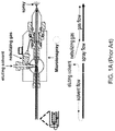
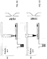
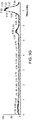
- FIG. 1A schematically illustrates a cross-sectional view of a prior art microionspray device including a liquid microjunction surface sampling probe and the fluid paths in the microionspray device.
- FIG. 1B a cross-sectional view of a proximal end of a prior art liquid microjunction surface sampling probe is shown.
- a proximal end of the liquid microjunction surface sampling probe is brought in proximity to a surface of a sample.
- the distance between the proximal end of the liquid microjunction surface sampling probe and the surface of the sample is maintained at a distance that enables formation of a liquid microjunction interface.
- the distance can be typically from 20 microns to 50 microns.
- a liquid which is referred to as an eluting solvent or an eluent, is pumped toward a surface of a sample through an annulus of a solvent delivery capillary located within a probe or an "emitter.”
- the liquid flow toward the sample is referred to as solvent flow.
- the sample can be any material that can be dissolved in the eluting solvent.
- the sample can be a thin tissue section having a thickness from 5 microns to 100 microns.
- the sample can be mounted to a substrate such as a glass slide.
- the eluting solvent can form a liquid microjunction with the surface of the sample, which is effected by holding the proximal end of the liquid microjunction surface sampling probe within a distance sufficient to maintain the liquid microjunction interface from the sample surface.
- FIG. 1B shows a set of dimensions for a proximal end of a coaxial liquid microjunction surface sampling probe.
- the eluting solvent is continuously fed to the periphery of a microjunction interface.
- a surface is an absorbent layer, i.e., as in the case of a piece of paper or a piece of fabric in which the sample, such as blood is embedded
- the eluting solvent is continuously absorbed at the periphery of the microjunction interface, disrupting the microjunction and making retrieval or extraction of the liquid and sample from the surface impossible as the eluate spreads throughout the surface.
- Hydrophobic surfaces will promote the formation of surface tension barriers at the interface of hydrophilic solvents. In this situation, provided the surface is not excessively hydrophobic preventing any penetration of the solvent, the droplets will maintain their integrity held intact by surface tension at the edges and still allow sufficient contact at and below the surface to extract sample. However, in order to allow the extraction solvent and the surface on which the sample is deposited to be effectively separated they must have dissimilar properties.
- the applicant's teachings relate to the desorption and dissolution of a sample from a surface by liquid extraction mechanisms.
- the applicant's teachings can allow for the direct analysis of a wide variety of surfaces with a wide variety of solvents and, in particular, can allow for the direct analysis of hydrophobic surfaces with hydrophilic solvents.
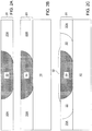
- a sample surface for depositing a sample on the sample surface comprises an absorptive layer 20 that can have an absorptive portion 20A.
- the sample can be embedded in the absorptive portion 20A.
- the absorptive portion 20A can be free of foreign material and can comprise a layer that can absorb a fluid.
- the sample can be deposited and can be embedded on the absorptive portion 20A of the absorptive layer 20 of the sample surface, as shown in region 30 of FIG. 2A .
- 2A can be prepared, for example, by providing a pristine absorptive layer consisting of the foreign-material-free absorptive portion 20A. Upon exposure of a portion of the foreign-material-free absorptive portion 20A to a sample material in the form of a fluid, the fluid can be absorbed or adsorbed to the foreign-material-free absorptive portion 20A, forming the sample region 30 comprising the fluid.
- the absorptive layer 20 since the pristine absorptive layer as provided has a porous structure before formation of the sample region 30, the absorptive layer 20, comprising the sample region 30 and the foreign-material-free absorptive portion 20A, also include a porous structure which can allow the sample material to be adsorbed in the sample region 30.
- the absorptive layer 20 can comprise a piece of paper, a piece of cloth, a porous ceramic material, or a combination thereof.
- the absorptive layer 20 can comprise, but is not limited to, a hydrophilic material.
- the thickness of the absorptive layer 20 can be, for example, from about 100 microns to about 10 mm, although as will be appreciated by those of skill in the art, lesser and greater thicknesses can also be employed.
- the absorptive layer 20 can be disposed on a top surface of a substrate 10.
- the substrate 10 can be a structure that provides mechanical support to the absorptive layer 20. As such, use of the substrate 10 is optional when the absorptive layer 20 alone provides sufficient mechanical support during subsequent analysis of the sample region 30. If the absorptive layer 20 does not provide sufficient mechanical strength to withstand subsequent analysis on the sample region 30, for example, as in the case of a thin paper tissue including a sample material, the substrate 10 can provide mechanical support to the absorptive layer 20.
- the top surface of the substrate 10 can contact the back side surface of the absorptive layer 20.
- the top surface of the substrate can be a hydrophobic surface.
- the combination of the absorptive layer 20 and the substrate 10 is herein referred to as a sample assembly (10, 20).
- the substrate 10 can include a metallic material, an insulator material, or any other rigid material provided that the substrate 10 can provide sufficient mechanical support during subsequent analysis of the embedded sample material in the sample region by liquid extraction methods.
- the sample region 30 can be formed within the absorptive layer 20 prior to bringing the absorptive layer 20 into contact with the substrate 10.
- the absorptive layer 20 can be brought into contact with the substrate prior to formation of the sample region 30 by exposure to a sample material.
- a hydrophobic material is applied to the absorptive layer 20, of the sample surface, which contains the sample 30.
- the hydrophobic material can be applied by spray coating around and on top of the sample region 30.
- the hydrophobic material can be applied to the entirety of the absorptive layer 20, for example, by immersion or by spin coating.
- a hydrophobic material can be applied, for example, by spraying or dipping onto an absorptive layer having regions where samples have been previously deposited, which may include, but is not limited to, a biological sample or a chemical sample.
- the hydrophobic material is embedded throughout the absorptive layer around the sample region to form a hydrophobic barrier peripheral to the sample preventing lateral diffusion of the extraction solvent and sample.
- the portion of the hydrophobic material applied over the sample region can form a thin and thus porous hydrophobic layer. Liquid extraction of the analyte molecules in the sample can occur through the porous hydrophobic barrier but the liquid is confined by the continuous hydrophobic barrier peripheral to the sample.
- the hydrophobic material is impregnated into the adsorptive layer prior to adding the sample.
- Patterned regions of hydrophobic barriers and undercoatings surrounding hydrophilic adsorptive areas for samples can confine the extraction liquid in a similar fashion to a non-patterned approach.
- the sample assembly (10, 20) can be dried to allow volatile components of the sprayed material to evaporate.
- the drying period for example, can be, but is not limited to, from about 1 minute to about 24 hours.
- the applied hydrophobic material can form a hydrophobic peripheral portion 22, which can comprise a hydrophobic material which can be embedded and can laterally confine the sample region 30.
- the entire periphery of the sample region 30 can be laterally surrounded by the hydrophobic peripheral portion 20.
- hydrophobic peripheral portion 22 can be formed as the applied hydrophobic material can be embedded in an absorptive portion 20A contacting the sample region 30.
- the absorptive portion 20 A can be substantially free of foreign material or it can comprise low foreign material.
- a hydrophobic layer 32 can be formed over the sample region 30.
- the hydrophobic layer 32 can be much thinner than the hydrophobic barrier 22 formed in the adsorbent material where no sample is present because sample has already saturated the adsorptive material.
- the thinness of layer 32 can be thinner than the thick deeply penetrating barrier formed at 22 because he sample has already saturated this area of the adsorptive material.
- the hydrophobic layer 32 can comprise the same material as the embedded hydrophobic material in the hydrophobic peripheral portion 22 but because it is much thinner, it has a degree of porosity allowing the solvent to penetrate into the sample while maintaining the property of preventing rapid and uncontrolled diffusion of the liquid throughout the adsorbent layer.
- the treatment of the absorptive layer 20 by application of the hydrophobic material can reduce the wettability of the surface of the absorptive layer 20 so that an extraction liquid or sprayed droplets do not diffuse into the non-sample portion of the layer.
- the hydrophobic peripheral portion 22 immediately adjacent to the sample can inhibit the radial elution of analyte and extraction solvent from the sample region 30 within the absorptive layer 20.
- the treatment of the absorptive layer 20 does not disrupt the spatial distribution of the embedded sample material within the sample region 30.
- the treatment of the absorptive layer 20 can allow the embedded sample material within the sample region 30 to be dissolved and extracted from the surface of the absorptive layer 20 during the operation of a liquid extraction.
- the treatment of the absorptive layer 20 does not contribute to a detrimental matrix effect, i.e., it does not result in ion suppression or inhibit analyte extraction from the surface.
- An example of a suitable hydrophobic material that can be applied to the absorptive layer 20 of the sample surface can be silicone.
- a commercially available source of silicone can be a silicone spray that can typically be employed as a lubricant or as a water proofing agent.
- silicone forms the hydrophobic peripheral portion 22 and the hydrophobic layer 32, which can impart hydrophobic character to the surface and the ability to form a stable liquid/solid interface.
- the thin silicone layer over the sample can have a degree of porosity allowing the extraction solvent to penetrate, dissolve the sample, and be withdrawn without dispersing and diffusing throughout the absorbent layer.
- the thick layer at 22 can be impermeable to the extraction solvent.
- Commercially available silicone sprays can include, but are not limited to, Carfa Magic TrioTM and Kiwi Camp DryTM.
- suitable hydrophobic materials that can be applied to the absorptive layer 20 of the sample surface are alkanes and fluorinated alkanes.
- Alkanes and fluorinated alkanes in the form of solids, liquids, or aerosols are often referred to as waxes, and can be applied to the surface by melting, painting, or spraying.
- Materials of this type can provide the option to pattern the adsorptive material defining regions that can comprise sample wells where samples can be deposited.
- the volume of the adsorptive sample well to be extracted by liquid can be controlled, and the extracted sample can be directly analyzed by atmospheric pressure ionization mass spectrometry.
- reagents that can form a chemical bond instead of forming a physical association can also be employed provided that such reagents can form the hydrophobic peripheral portion 22 and optionally the hydrophobic layer 32 to render at least a portion of the top surface of the absorptive layer 20 hydrophobic.
- the hydrophobic material can be in a solid phase at the operating temperature of the liquid extraction surface sampling probe.
- the hydrophobic material can be in a solid phase at 293.15 K, i.e., at room temperature.
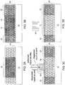
- FIG. 3A a schematic cross-sectional view of the sample assembly (10, 20) is shown prior to application of a hydrophobic material.
- the sample can be added to the adsorptive material in region 30. This step corresponds to the processing step of FIG. 2B .
- the porosity of the absorptive layer 20 is schematically illustrated by circles.
- the embedded sample material of the sample region 30 can be located between structural units, such as a fiber, of the absorptive layer 30.
- the embedded sample material of the sample region 30 can permeate into each structural unit, such as a fiber, of the absorptive layer 30.
- FIG. 3B a schematic cross-sectional view of the sample assembly (10, 20) is shown after application of a hydrophobic material. This step corresponds to the processing step of FIG. 2C .
- a thin, porous hydrophobic layer 32 can cover the sample.
- At least one device 40 is brought to the top surface of the sample assembly (10, 20).
- the at least one device 40 is configured to dispense a liquid onto the sample assembly and to extract the liquid from the sample assembly.
- the thin hydrophobic layer can allow solvent to penetrate and be extracted but inhibits excessive spreading across the surface.
- the at least one device 40 is a single device that dispenses and extracts the liquid.
- At least one device 40 is a liquid extraction surface sampling probe.
- the liquid extraction surface sampling probe can be brought into proximity with the sample region 30.
- a liquid can be fed to the sample region 30, for example, through an annular capillary.
- the liquid can be a solvent that can be capable of dissolving the sample embedded in region 30.
- the liquid is referred to as an eluting solvent or an eluent.
- the liquid in the sample region 30 can dissolve the embedded sample in region 30.
- the sample region 30 during the dissolution of the embedded material by the presence of the liquid is herein referred to as a dissolving sample region 34.
- the liquid that passes through an inner capillary and pulled away from the dissolving sample region 34 forms a stream of eluate.
- the composition of the eluate can comprise the liquid of the eluent and the dissolved material that originates from the embedded sample material forming a dissolved sample material.
- the liquid microjunction surface sampling probe can be configured to provide the stream of eluate while maintaining a liquid microjunction interface between a proximal surface of the liquid microjunction surface sampling probe and the thin hydrophobic layer covering the sample in the absorptive layer 20.
- the proximal surface of the liquid microjunction surface sampling probe can be the end surface of the housing or the outer tube that surrounds the annular capillary that can be placed close to the surface of the absorptive layer 20 during the extraction step.
- the liquid microjunction interface can be formed between the liquid extraction surface sampling probe and the top surface of the absorptive layer 20 over the dissolving sample region 34.
- the liquid extraction surface sampling probe can be a sealing surface sampling probe (SSSP).
- the liquid extraction surface sampling probe can include at least one inlet (not shown) for letting in the liquid, the stream of eluent, and an outlet (not shown) for letting out the stream of eluate.
- the inlet can be contiguously connected to the annular capillary through which the eluent can flow toward the absorptive layer 20.
- the outlet can be contiguously connected to the inner capillary through which the stream of eluate can flow.
- the end of the inner capillary can be the outlet dispensing into an atmospheric pressure ionization source of a mass spectrometer.
- At least one device 40 can be configured to dispense a liquid onto the sample assembly and also withdraw the dissolved sample material from the sample assembly.
- At least one device can be configured to pneumatically generate a stream of charged droplets onto the sample assembly, similar to the device shown in FIG. 1A .
- the high velocity charged droplets can momentarily contact the sample material on or embedded in the sample surface and can dissolve the sample material.
- the charged droplets can extract, in a fashion similar to the microliquid junction, the dissolved sample material from the sample surface and can rebound from the sample surface into an ionization device.
- the absorptive layer 20 can include an analyzed area 31 laterally contacting the hydrophobic peripheral portion 22.
- the extent of the lateral diffusion of the liquid can be limited by the hydrophobic peripheral portion 22 that laterally surrounds or otherwise laterally confines the liquid within the dissolving sample region 34 during the extraction operation. Therefore, once the extraction operation is complete, the entirety of the analyzed area can be substantially free of any foreign material, i.e. can have substantially the same composition as the original material of the absorptive layer 20 before the sample region 30 is formed therein.
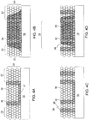
- a sample well 35 can be formed within the adsorptive material before the sample is added, for example, by patterning layers of wax into side barriers 36 and a bottom barrier 37 as shown in FIG 4A .
- sample When sample is added to the well, it can fill to a constant volume as shown in FIG 4B and excess sample can spill over the barrier spreading into adjacent adsorptive areas.
- a constant analysis volume can be obtained when excess sample is available and accurate pipetting of sample is not practical.
- an additional hydrophobic barrier 38 can surround the sampling area creating an adsorptive moat 39.
- FIG 4D in various embodiments according to the applicant's teachings, when excess sample overflows out of the sample well 30, it can be contained and prevented from spreading to other regions of the adsorptive paper by the moat 39.
- the at least one device 40 in FIGS. 3C and 3D can be replaced with a set of devices configured to dispense a liquid onto a sample assembly and to extract or retrieve the liquid from the sample assembly.
- a plurality of sample assemblies can be analyzed sequentially in various embodiments.
- the at least one device can dispense a liquid onto a sample assembly and extract the liquid from the sample assembly simultaneously or with a time interval between the dispensation and the extraction. Further, the at least one device can dispense a liquid onto the sample assembly continuously or intermittently. Likewise, the at least one device can extract the liquid from the sample assembly continuously or intermittently.
- At least one exposed well can be filled with a liquid, which can be an extraction solvent, to be used for the extraction of dissolved materials from a sample region in the sample assembly.
- a liquid which can be an extraction solvent
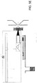
- the robotic arm picks up a conductive pipette tip and moves the tip to a position above the well containing the extraction solvent as shown in FIG. 5A .
- the tip can be lowered into the well, and the liquid can be aspirated into the tip as shown in FIG. 5B .
- the pipette tip can be positioned above the sample region of the sample assembly (which corresponds to the sample region 30 in FIG. 2C ) to be sampled.
- a specific volume of the liquid can be dispensed onto the sample from the tip.
- the liquid can be dispensed without breaking a liquid junction between the pipette tip and surface of the sample region of the sample assembly as shown in FIG. 5C .
- the liquid can be confined within the sample region; see the sample region 30 in FIG. 2C , due to the presence of the hydrophobic peripheral portion 22 without being absorbed into a foreign-material-free absorptive portion 20A (See FIG. 2C ).
- the diameter of such a liquid junction can be on the order of the dimension of the pipette tip, which is typically about 1 mm in diameter.
- the distance between the tip and the surface, and the volumes aspirated and dispensed can be optimized for each individual surface.
- the solution containing a dissolved sample material subsequently can be aspirated back into the tip of the pipette as shown in FIG. 5D .
- the collected liquid, the sample solution can be sprayed through a nanospray nozzle as shown in FIG. 5E . If a mass spectrometer is provided at the nozzle of the nanospray, the mass spectrometric response of the analyte of interest can be collected, for example, using selected reaction monitoring (SRM).
- SRM selected reaction monitoring
- the robotic arm can withdraw from the well and engage the pipette tip to the back of a nanospray chip, which is an electrospray ionization (ESI) chip.
- ESI electrospray ionization
- This chip contains microfabricated nozzles to generate nanoelectrospray ionization of liquid samples at flow rates of 20-500 nl/min.
- the nanoelectrospray can be initiated by applying the appropriate high voltage to the pipette tip and gas pressure on the liquid. If necessary, each nozzle and pipette tip can be used only once to eliminate any possibility of sample-to-sample carryover.
- the mechanical components of the at least one device 40 of this embodiment are described in Vilmoz Kertesz and Gary J.
- an absorptive layer coated with a hydrophobic material according to the applicant's teachings is compared to an untreated surface.
- Absorbed water droplets on an untreated hydrophilic high performance thin layer chromatography normal phase (HPTLC) plate are shown as two blurred spots on the left side and unabsorbed water droplets on a hydrophobic-coating treated normal phase HPTLC plate treated with a hydrophobic coating are shown as two water droplets in the middle.
- the material that provides the hydrophobic coating in this example is silicone.
- the sample region corresponds to the area including the writing "OBMS” and "ORNL.”
- the hydrophobic coating renders the surface of the hydrophobic-coating treated normal phase HPTLC plate hydrophobic so that the water droplets ball up on the surface instead of being absorbed in the HPTLC plate as shown in the untreated plate.
- a second example of a hydrophobic-coating-treated absorptive layer is shown, which is a hydrophobic-coating treated absorbent cleaning tissue (KimWipes®) including several sample regions.
- the formation of hydrophobic coating peripheral portions and the hydrophobic layers renders the surface of the treated absorbent cleaning tissue hydrophobic.
- the hydrophobic coating peripheral portions on the hydrophobic-coating-treated absorbent cleaning tissue laterally confine the embedded sample material after a liquid is applied to the sample regions, thereby enabling the liquid extraction surface sampling probe to collect all of the embedded sample material without loss due to lateral outward diffusion within the absorbent cleaning tissue.
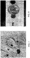
- FIG. 8 a third example of a hydrophobic-coating-treated absorptive layer according to the applicant's teachings is shown, which is a hydrophobic-coating treated blood spot paper.
- Blood spot paper has been widely used for analysis of blood samples. Due to the absorptive nature of the blood spot paper, however, subjecting an embedded material in a blood spot paper without hydrophobic treatment results in lateral outward diffusion of the embedded material when a liquid is applied, for example, in an attempt to generate an eluate employing a liquid extraction surface sampling probe.
- the hydrophobic-coating treatment on the blood spot paper renders the surface of the blood spot paper hydrophobic as illustrated by the hydrophobic-coating-treated absorptive layer in FIG. 8 .
- the hydrophobic-coating-treated blood spot paper can be subjected to analysis by employing a liquid extraction surface sampling probe without the loss of the embedded sample material, i.e., the blood sample, due to lateral outward diffusion within the blood spot paper.
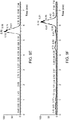
- FIGS. 9A - 9G are time-dependent readouts at various m/z settings from a liquid microjunction surface sample probe scan of a post-development treated normal phase HPTLC plate obtained from chromatography on a sample of a goldenseal root extract.
- the goldenseal root extract is a popular herbal product derived from the goldenseal plant.
- the goldenseal root extract includes many chemicals such as berberine, hydrasitine, and hydrastinine.
- a high performance thin layer chromatography (HPTLC) run was performed on the goldenseal root extract employing a normal phase HPTLC plate, which is hydrophilic.
- the normal phase HPTLC plate was subsequently treated with a hydrophobic coating according the methods of the applicant's teachings so that the surface of the normal phase HPTLC plate became hydrophobic.
- Each band of the normal phase HPTLC was subjected to analysis by a liquid extraction surface sampling probe.
- the eluate from each band was subjected to mass spectroscopy and a time dependent reading was taken at a predetermined m/z setting corresponding to the expected composition of each band.
- FIG. 9A shows the time-dependent readout at the m/z setting of 190 from the first liquid extraction surface sampling run on the first band.
- the x-axis of FIG. 9A is the time in minutes from the initiation of the first liquid extraction surface sampling run, and the y-axis is the intensity of the peak in arbitrary units as detected by the mass spectrometer.
- the m/z setting of 190 corresponds to hydrastinine, a compound of the goldenseal root extract.
- FIG. 9B shows the time-dependent readout at the m/z setting of 384 from the second liquid extraction surface sampling run on the second band.
- the x-axis of FIG. 9B is the time in minutes from the initiation of the second liquid extraction surface sampling run, and the y-axis is the intensity of the peak in arbitrary units as detected by the mass spectrometer.
- the m/z setting of 384 corresponds to hydrastine, a compound of the goldenseal root extract.
- FIG. 9C shows the time-dependent readout at the m/z setting of 338 from the third liquid extraction surface sampling run on the third band.
- the x-axis of FIG. 9C is the time in minutes from the initiation of the third liquid extraction surface sampling run, and the y-axis is the intensity of the peak in arbitrary units as detected by the mass spectrometer.
- the m/z setting of 338 corresponds to jatrorrhizine, a compound of the goldenseal root extract.
- FIG. 9D shows the time-dependent readout at the m/z setting of 352 from the fourth liquid extraction surface sampling run on the fourth band.
- the x-axis of FIG. 9D is the time in minutes from the initiation of the fourth liquid extraction surface sampling run, and the y-axis is the intensity of the peak in arbitrary units as detected by the mass spectrometer.
- the m/z setting of 352 corresponds to berberastine, a compound of the goldenseal root extract.
- FIG. 9E shows the time-dependent readout at the m/z setting of 336 from the fifth liquid extraction surface sampling run on the fifth band.
- the x-axis of FIG. 9E is the time in minutes from the initiation of the fifth liquid extraction surface sampling run, and the y-axis is the intensity of the peak in arbitrary units as detected by the mass spectrometer.
- the m/z setting of 336 corresponds to berberine, a compound of the goldenseal root extract.
- FIG. 9F shows the time-dependent readout at the m/z setting of 370 from the sixth liquid extraction surface sampling run on the sixth band.
- the x-axis of FIG. 9F is the time in minutes from the initiation of the sixth liquid extraction surface sampling run, and the y-axis is the intensity of the peak in arbitrary units as detected by the mass spectrometer.
- the m/z setting of 370 corresponds to Mapline, a compound of the goldenseal root extract.
- FIG. 9G shows the time-dependent readout at the m/z setting of 340 from the seventh liquid extraction surface sampling run on the seventh band.
- the x-axis of FIG. 9G is the time in minutes from the initiation of the seventh liquid extraction surface sampling run, and the y-axis is the intensity of the peak in arbitrary units as detected by the mass spectrometer.
- the m/z setting of 340 corresponds to tetrahydrobeberine, a compound of the goldenseal root extract.
- each liquid extraction surface sampling run on a band in the hydrophobic-coating-treated normal phase HPTLC plate extracted the chemical of the band successfully without extracting materials of another band or contaminating another band by pushing out the material of the band outward.
- the containment of the liquid, i.e., the eluting solvent within each sample area of an individual band can be effected by the presence of the hydrophobic peripheral portions around each band.
- the hydrophobic coating method of the applicant's teachings can be employed in combination with a liquid extraction surface sampling probe to provide enhanced sensitivity, reduced sample loss, and elimination of contamination of other sample regions when multiple sample regions are present on the same absorptive layer.
Landscapes
- Physics & Mathematics (AREA)
- Health & Medical Sciences (AREA)
- Life Sciences & Earth Sciences (AREA)
- Chemical & Material Sciences (AREA)
- Analytical Chemistry (AREA)
- Biochemistry (AREA)
- General Health & Medical Sciences (AREA)
- General Physics & Mathematics (AREA)
- Immunology (AREA)
- Pathology (AREA)
- Sampling And Sample Adjustment (AREA)
- Other Investigation Or Analysis Of Materials By Electrical Means (AREA)
- Automatic Analysis And Handling Materials Therefor (AREA)
Claims (28)
- Système pour extraire un échantillon d'une surface d'échantillon à l'aide d'un liquide, comprenant :un dispositif pour collecter un échantillon comprenant- une couche absorbante (20) constituée par la surface d'échantillon et comprenant un matériau poreux pour collecter un échantillon, ledit matériau poreux pour collecter un échantillon étant capable d'absorber l'échantillon de telle sorte que l'échantillon pénètre sous la surface du matériau poreux pour collecter un échantillon, une région d'échantillon (30) pour collecter un échantillon et des parties périphériques (22) du matériau poreux pour collecter un échantillon définissant des régions barrières pour contenir un flux de liquide d'extraction d'échantillon autour de la région d'échantillon (30) ; et- un matériau hydrophobe imprégné dans le matériau poreux pour collecter un échantillon dans les parties périphériques (22) pour contenir le flux de liquide d'extraction d'échantillon,caractérisé en ce quele matériau hydrophobe est incorporé dans le matériau poreux pour collecter un échantillon afin de former une barrière hydrophobe périphérique à l'échantillon, et il définit des motifs dans le matériau poreux pour collecter un échantillon, formant des puits d'échantillon ;- une sonde d'échantillonnage de surface par extraction liquide pour appliquer le liquide d'extraction à la surface du matériau poreux pour collecter un échantillon, et pour prélever un liquide d'extraction contenant un échantillon extrait de la surface du matériau poreux pour collecter un échantillon par le biais de la sonde d'échantillonnage de surface par extraction liquide, ladite sonde d'échantillonnage de surface par extraction liquide étant apte à disperser le liquide contenant un échantillon extrait dans une source d'ionisation, afin d'ioniser le matériau d'échantillon extrait dissous en aval du matériau poreux et de la sonde d'échantillonnage de surface par extraction liquide.
- Système selon la revendication 1, dans lequel le matériau poreux pour collecter un échantillon comprend un matériau hydrophile.
- Système selon la revendication 1, dans lequel le matériau poreux pour collecter un échantillon est choisi dans un groupe consistant en du papier, du tissu, un matériau céramique poreux et une combinaison de ceux-ci.
- Système selon la revendication 1, dans lequel un substrat procure un support mécanique au matériau poreux pour collecter un échantillon.
- Système selon la revendication 1, dans lequel le matériau hydrophobe est choisi dans un groupe consistant en du silicone, un alcane fluoré et des cires.
- Système selon la revendication 1 comprenant en outre des barrières hydrophobes et des fossés supplémentaires pour contenir le débordement de l'échantillon provenant des puits d'échantillon.
- Système selon la revendication 1, dans lequel le matériau hydrophobe comprend une phase solide à 293,15 K.
- Système selon la revendication 1, dans lequel le matériau poreux pour collecter un échantillon est apte à collecter un échantillon comprenant un matériau biologique.
- Système selon la revendication 8, dans lequel le matériau poreux pour collecter un échantillon est apte à collecter un échantillon comprenant du sang.
- Système selon la revendication 1, dans lequel la sonde d'échantillonnage est apte à appliquer un liquide comprenant un solvant qui dissout l'échantillon.
- Système selon la revendication 1, dans lequel un dispositif pour ioniser le matériau d'échantillon dissous est choisi dans le groupe consistant en un dispositif d'ionisation par pulvérisation électrique, un dispositif d'ionisation chimique atmosphérique, un dispositif d'ionisation par plasma à couplage inductif et un dispositif de photo ionisation atmosphérique.
- Système selon la revendication 11, dans lequel la sonde d'échantillonnage de surface par extraction liquide est apte à disperser le liquide contenant un échantillon extrait dans une source d'ionisation d'un spectromètre de masse.
- Procédé d'extraction d'un échantillon d'un échantillon ayant une surface, le procédé comprenant les étapes consistant à :fournir un dispositif pour collecter un échantillon comprenant une couche absorbante (20) comprenant un matériau poreux pour collecter un échantillon et une région d'échantillon (30) pour collecter un échantillon ;fournir des parties périphériques (22) définissant des régions barrières autour de la région d'échantillon dans le matériau pour collecter un échantillon en appliquant un matériau hydrophobe au matériau poreux pour collecter un échantillon autour de la région d'échantillon afin d'empêcher l'écoulement du liquide d'extraction et de l'échantillon à travers les régions barrières, le matériau hydrophobe étant incorporé dans le matériau poreux pour collecter un échantillon afin de former une barrière hydrophobe périphérique à la région d'échantillon et définissant des motifs dans le matériau poreux pour collecter un échantillon en formant des puits d'échantillon ;déposer un échantillon dans la région d'échantillon à la surface du matériau poreux pour collecter un échantillon, l'échantillon pénétrant sous la surface du matériau poreux pour collecter un échantillon ;distribuer un liquide d'extraction d'échantillon sur la surface du matériau pour collecter un échantillon avec une sonde d'échantillonnage de surfaces par extraction liquide afin de dissoudre l'échantillon pour former un matériau d'échantillon dissous, les régions barrières inhibant la propagation du liquide d'extraction à travers le matériau poreux pour collecter un échantillon ;extraire le matériau d'échantillon dissous de la surface d'échantillon avec la sonde d'échantillonnage de surfaces par extraction liquide par le biais de la sonde d'échantillonnage de surfaces par extraction liquide, le liquide d'extraction comprenant l'échantillon extrait prélevé du matériau poreux pour collecter un échantillon par le biais de la sonde d'échantillonnage de surface par extraction liquide, ladite sonde d'échantillonnage de surface par extraction liquide étant apte à disperser le liquide contenant l'échantillon extrait dans une source d'ionisation ; etcomprenant en outre l'étape consistant à ioniser le matériau d'échantillon extrait dissous en aval du matériau poreux et de la sonde d'échantillonnage de surface.
- Procédé selon la revendication 13, dans lequel le matériau poreux pour collecter un échantillon comprend un matériau hydrophile.
- Procédé selon la revendication 13, dans lequel le matériau poreux pour collecter un échantillon est choisi dans un groupe consistant en du papier, du tissu, un matériau céramique poreux et une combinaison de ceux-ci.
- Procédé selon la revendication 13, dans lequel un support mécanique est fourni par un substrat au matériau poreux pour collecter un échantillon.
- Procédé selon la revendication 13, dans lequel le matériau hydrophobe est choisi dans un groupe consistant en du silicone, un alcane fluoré et des cires.
- Procédé selon la revendication 13, comprenant en outre l'étape consistant à fournir des barrières hydrophobes et des fossés supplémentaires pour contenir le débordement de l'échantillon provenant des puits d'échantillon.
- Procédé selon la revendication 13, dans lequel une couche hydrophobe est prévue sur la région du matériau poreux pour collecter un échantillon contenant l'échantillon.
- Procédé selon la revendication 13, dans lequel le matériau hydrophobe comprend une phase solide à 293,15 K.
- Procédé selon la revendication 13, dans lequel l'échantillon comprend un matériau biologique.
- Procédé selon la revendication 21, dans lequel l'échantillon comprend du sang.
- Procédé selon la revendication 13, dans lequel le liquide comprend un solvant qui qui dissout l'échantillon.
- Procédé selon la revendication 13, dans lequel un dispositif pour ioniser le matériau d'échantillon dissous est choisi dans le groupe consistant en un dispositif d'ionisation par pulvérisation électrique, un dispositif d'ionisation chimique atmosphérique, un dispositif d'ionisation par plasma à couplage inductif et un dispositif de photo ionisation atmosphérique.
- Procédé selon la revendication 24, dans lequel le matériau d'échantillon dissous ionisé est analysé par un spectromètre de masse.
- Système selon la revendication 1, dans lequel des régions barrières définissent des régions barrières latérales et une région barrière inférieure connectée.
- Système selon la revendication 26, dans lequel les région barrière latérales des puits sont entourées de matériau poreux pour prélever un échantillon non enrobé afin de définir une région de débordement.
- Système selon la revendication 27, dans lequel la région de débordement est entourée d'une région barrières définissant des parois de fossé pour confiner les solvants débordant d'un puits d'échantillon à l'intérieur de la région de débordement.
Applications Claiming Priority (2)
| Application Number | Priority Date | Filing Date | Title |
|---|---|---|---|
| US33248610P | 2010-05-07 | 2010-05-07 | |
| PCT/US2011/035604 WO2011140492A2 (fr) | 2010-05-07 | 2011-05-06 | Système et procédé permettant d'extraire un échantillon d'une surface |
Publications (3)
| Publication Number | Publication Date |
|---|---|
| EP2567395A2 EP2567395A2 (fr) | 2013-03-13 |
| EP2567395A4 EP2567395A4 (fr) | 2017-12-27 |
| EP2567395B1 true EP2567395B1 (fr) | 2019-12-18 |
Family
ID=44904512
Family Applications (1)
| Application Number | Title | Priority Date | Filing Date |
|---|---|---|---|
| EP11778447.0A Active EP2567395B1 (fr) | 2010-05-07 | 2011-05-06 | Système et procédé permettant d'extraire un échantillon d'une surface |
Country Status (6)
| Country | Link |
|---|---|
| US (1) | US9063047B2 (fr) |
| EP (1) | EP2567395B1 (fr) |
| JP (1) | JP5819943B2 (fr) |
| CN (1) | CN103038857B (fr) |
| CA (1) | CA2798638C (fr) |
| WO (1) | WO2011140492A2 (fr) |
Families Citing this family (31)
| Publication number | Priority date | Publication date | Assignee | Title |
|---|---|---|---|---|
| US8791411B2 (en) * | 2008-05-06 | 2014-07-29 | Massachusetts Institute Of Technology | Method and apparatus for a porous electrospray emitter |
| US10125052B2 (en) | 2008-05-06 | 2018-11-13 | Massachusetts Institute Of Technology | Method of fabricating electrically conductive aerogels |
| US8324593B2 (en) * | 2008-05-06 | 2012-12-04 | Massachusetts Institute Of Technology | Method and apparatus for a porous metal electrospray emitter |
| US8785881B2 (en) | 2008-05-06 | 2014-07-22 | Massachusetts Institute Of Technology | Method and apparatus for a porous electrospray emitter |
| CA2798413A1 (fr) * | 2010-06-10 | 2011-12-15 | Western Michigan University Research Foundation | Dispositif de collecte de matieres sur des surfaces |
| US10308377B2 (en) | 2011-05-03 | 2019-06-04 | Massachusetts Institute Of Technology | Propellant tank and loading for electrospray thruster |
| ES2922304T3 (es) * | 2012-12-20 | 2022-09-13 | Merck Patent Gmbh | Método y dispositivo para llevar a cabo cromatografía en capa fina |
| WO2014169982A1 (fr) * | 2013-04-17 | 2014-10-23 | Merck Patent Gmbh | Plaque de chromatographie sur couche mince, procédé de fabrication d'une telle plaque, ainsi que procédé de réalisation d'une séparation par chromatographie sur couche mince |
| US9358556B2 (en) | 2013-05-28 | 2016-06-07 | Massachusetts Institute Of Technology | Electrically-driven fluid flow and related systems and methods, including electrospinning and electrospraying systems and methods |
| WO2015070352A1 (fr) * | 2013-11-15 | 2015-05-21 | Smiths Detection Montreal Inc. | Source d'ions pour ionisation de surface apci concentrique, guide d'ions et procédé d'utilisation associé |
| JP5971289B2 (ja) * | 2014-08-20 | 2016-08-17 | 株式会社 イアス | 基板局所の自動分析装置及び分析方法 |
| US9390901B2 (en) | 2014-10-31 | 2016-07-12 | Ut-Battelle, Llc | System and method for liquid extraction electrospray-assisted sample transfer to solution for chemical analysis |
| US10060838B2 (en) | 2015-04-09 | 2018-08-28 | Ut-Battelle, Llc | Capture probe |
| US9632066B2 (en) | 2015-04-09 | 2017-04-25 | Ut-Battelle, Llc | Open port sampling interface |
| US10041866B2 (en) * | 2015-04-24 | 2018-08-07 | University Of South Carolina | Reproducible sample preparation method for quantitative stain detection |
| WO2017038709A1 (fr) | 2015-09-03 | 2017-03-09 | 浜松ホトニクス株式会社 | Procédé de désorption/ionisation laser assistée par surface, procédé de spectrométrie de masse et dispositif de spectrométrie de masse |
| CN109789420B (zh) | 2016-09-02 | 2021-09-24 | 得克萨斯大学体系董事会 | 收集探针及其使用方法 |
| US10141855B2 (en) | 2017-04-12 | 2018-11-27 | Accion Systems, Inc. | System and method for power conversion |
| US20210343515A1 (en) * | 2017-06-08 | 2021-11-04 | Board Of Regents, The University Of Texas System | Systems and methods for microarray droplet ionization analysis |
| AU2018373391A1 (en) | 2017-11-27 | 2020-06-11 | Board Of Regents, The University Of Texas System | Minimally invasive collection probe and methods for the use thereof |
| US11125657B2 (en) | 2018-01-30 | 2021-09-21 | Ut-Battelle, Llc | Sampling probe |
| EP3973182A4 (fr) | 2019-05-21 | 2023-06-28 | Accion Systems, Inc. | Appareil d'émission par électronébulisation |
| CN110729169B (zh) * | 2019-10-15 | 2022-01-18 | 宁波谱秀医疗设备有限责任公司 | 一种便携式质谱仪 |
| CN110729170B (zh) * | 2019-10-17 | 2022-04-26 | 浙江品玉精密科技有限公司 | 一种离子源 |
| CN110729168B (zh) * | 2019-10-17 | 2022-04-26 | 南京品生医疗科技有限公司 | 一种小型质谱仪 |
| CN111208190B (zh) * | 2020-01-10 | 2021-05-18 | 中国科学院深圳先进技术研究院 | 一种采样头、采样系统、质谱成像装置和采样方法 |
| CN111199863B (zh) * | 2020-01-10 | 2021-07-16 | 中国科学院深圳先进技术研究院 | 一种采样系统、质谱分析装置、采样方法和质谱分析方法 |
| CN111208191B (zh) * | 2020-01-10 | 2021-05-18 | 中国科学院深圳先进技术研究院 | 一种采样头、采样系统、质谱成像装置和采样方法 |
| JP2022024306A (ja) * | 2020-07-15 | 2022-02-09 | キオクシア株式会社 | 分析装置および分析方法 |
| GB202100096D0 (en) * | 2021-01-05 | 2021-02-17 | Micromass Ltd | Sample Analysis |
| CN113252381A (zh) * | 2021-05-27 | 2021-08-13 | 大连海事大学 | 一种对大面积表面的溶解法取样装置 |
Family Cites Families (65)
| Publication number | Priority date | Publication date | Assignee | Title |
|---|---|---|---|---|
| GB1272409A (en) | 1969-07-26 | 1972-04-26 | Kuibyshevsky Awiazionny | Eddy-currents transducer for checking surfaces of metal articles |
| GB1451599A (en) * | 1972-07-04 | 1976-10-06 | Wellcome Found | Biological reagent |
| US4132527A (en) * | 1974-01-09 | 1979-01-02 | Shionogi & Co., Ltd. | Diagnostic compositions, diagnosing instruments, and methods of manufacturing same |
| US4865199A (en) * | 1985-07-12 | 1989-09-12 | John Zimmer | Disposable combination cup and base |
| DE3779334D1 (de) * | 1986-02-12 | 1992-07-02 | Erez Forensic Technology Ltd | Verfahren und testsatz zur drogenbestimmung. |
| US4745809A (en) | 1986-08-12 | 1988-05-24 | Grumman Aerospace Corporation | Composite analyzer tester |
| US4726487A (en) * | 1986-10-17 | 1988-02-23 | George Mitri | Disposable beverage container |
| DE4200497A1 (de) | 1992-01-10 | 1993-07-15 | Bayer Ag | Verfahren und vorrichtung zur schnellen identifizierung von kunststoffen mit hilfe der massenspektrometrie |
| DE4207074A1 (de) | 1992-03-06 | 1993-09-09 | Lang Volker | Pipetiervorrichtung fuer chemische analyseautomaten mit besonderer eignung zur probenentnahme aus kapillaren |
| US5205473A (en) * | 1992-03-19 | 1993-04-27 | Design By Us Company | Recyclable corrugated beverage container and holder |
| US5271798A (en) | 1993-03-29 | 1993-12-21 | Micron Technology, Inc. | Method for selective removal of a material from a wafer's alignment marks |
| JPH07159293A (ja) | 1993-12-10 | 1995-06-23 | Sony Corp | 表面分析方法及び表面分析装置 |
| JP3348634B2 (ja) | 1996-09-19 | 2002-11-20 | 日本鋼管株式会社 | レーザ気化分析方法 |
| US5783938A (en) | 1997-02-24 | 1998-07-21 | Contamination Studies Laboratories, Inc. | Method and apparatus for the quantitative measurement of the corrosivity effect of residues present on the surface of electronic circuit assemblies |
| JPH11304666A (ja) * | 1998-04-24 | 1999-11-05 | Hitachi Ltd | 試料ハンドリングツールおよびその使用方法 |
| US6140639A (en) | 1998-05-29 | 2000-10-31 | Vanderbilt University | System and method for on-line coupling of liquid capillary separations with matrix-assisted laser desorption/ionization mass spectrometry |
| CA2366625C (fr) * | 1999-03-22 | 2008-01-22 | Analytica Of Branford, Inc. | Spectrometrie de masse en mode electrospray et apci permettant d'effectuer une analyse par injection de flux |
| US6290863B1 (en) | 1999-07-31 | 2001-09-18 | Micron Technology, Inc. | Method and apparatus for etch of a specific subarea of a semiconductor work object |
| WO2001032245A1 (fr) | 1999-11-03 | 2001-05-10 | Cornell Research Foundation, Inc. | Dispositif miniature de transfert de fluide |
| IL133115A0 (en) | 1999-11-24 | 2001-03-19 | Yeda Res & Dev | Method for micropatterning of surfaces |
| US6495824B1 (en) * | 2000-03-13 | 2002-12-17 | Bechtel Bwxt Idaho, Llc | Ion mobility spectrometer, spectrometer analyte detection and identification verification system, and method |
| JP4927287B2 (ja) | 2000-03-31 | 2012-05-09 | マイクロニックス、インコーポレーテッド | タンパク質の結晶化のマイクロ流動体装置 |
| US6569384B2 (en) | 2000-08-21 | 2003-05-27 | Ut-Battelle, Llc | Tissue-based water quality biosensors for detecting chemical warfare agents |
| CA2444524A1 (fr) * | 2001-04-17 | 2002-10-24 | Ista, S.P.A. | Procedes de detection par spectrometrie de masse et quantification de proteines cibles specifiques dans des echantillons biologiques complexes |
| JP2003035671A (ja) | 2001-07-25 | 2003-02-07 | Kawasaki Steel Corp | レーザ多段励起発光分光分析方法及びその装置 |
| US6995024B2 (en) * | 2001-08-27 | 2006-02-07 | Sri International | Method and apparatus for electrostatic dispensing of microdroplets |
| US6864480B2 (en) * | 2001-12-19 | 2005-03-08 | Sau Lan Tang Staats | Interface members and holders for microfluidic array devices |
| US7459127B2 (en) * | 2002-02-26 | 2008-12-02 | Siemens Healthcare Diagnostics Inc. | Method and apparatus for precise transfer and manipulation of fluids by centrifugal and/or capillary forces |
| WO2003083130A2 (fr) | 2002-03-28 | 2003-10-09 | The Johns Hopkins University | Detection de parasites du paludisme par spectrometrie de masse |
| US6803566B2 (en) | 2002-04-16 | 2004-10-12 | Ut-Battelle, Llc | Sampling probe for microarray read out using electrospray mass spectrometry |
| US7901939B2 (en) | 2002-05-09 | 2011-03-08 | University Of Chicago | Method for performing crystallization and reactions in pressure-driven fluid plugs |
| WO2004005553A1 (fr) * | 2002-07-10 | 2004-01-15 | Massachusetts Institute Of Technology | Appareil et procede permettant d'isoler un acide nucleique d'un echantillon |
| US20040023410A1 (en) | 2002-08-05 | 2004-02-05 | Catherine Stacey | Method and apparatus for continuous sample deposition on sample support plates for liquid chromatography-matrix-assisted laser desorption/ionization mass spectrometry |
| EP2722869A1 (fr) * | 2002-10-29 | 2014-04-23 | Target Discovery, Inc. | Procede permittant d'accroitre l'efficacie d'Ionisation en spectrosopie de masse |
| US7034854B2 (en) | 2002-11-12 | 2006-04-25 | Nanoink, Inc. | Methods and apparatus for ink delivery to nanolithographic probe systems |
| JP3915677B2 (ja) | 2002-11-29 | 2007-05-16 | 日本電気株式会社 | 質量分析用チップおよびこれを用いたレーザー脱離イオン化飛行時間型質量分析装置、質量分析システム |
| EP2340890B1 (fr) * | 2003-04-03 | 2016-10-19 | Fluidigm Corporation | Procédé pour réaliser PCR numérique |
| CA2541536A1 (fr) * | 2003-10-10 | 2005-04-21 | Protein Discovery, Inc. | Procedes et dispositifs pour concentration et epuration d'analytes en vue d'une analyse chimique incluant une spectrometrie de masse (ms) a desorption-ionisation par impact laser assistee par matrice (maldi) |
| US20050178959A1 (en) * | 2004-02-18 | 2005-08-18 | Viorica Lopez-Avila | Methods and compositions for assessing a sample by maldi mass spectrometry |
| US20050276937A1 (en) * | 2004-06-14 | 2005-12-15 | Sports Media, Inc. | Container and method of making a container |
| US8679420B2 (en) * | 2004-07-22 | 2014-03-25 | Immunostics, Inc. | Fecal sampling device and method |
| JP2006059641A (ja) | 2004-08-19 | 2006-03-02 | Nissan Motor Co Ltd | 二次電池用電極、および、これを用いた二次電池 |
| DE102004048380A1 (de) | 2004-10-01 | 2006-04-13 | Forschungszentrum Jülich GmbH | Verfahren und Vorrichtung zur quantitativen Elementanalysen in der Laserablations-ICP-MS mittels direkter on-line Lösungskalibration |
| AU2005334566A1 (en) * | 2005-07-19 | 2007-01-25 | Attogenix Biosystems Pte Ltd. | Device for processing a biological and/or chemical sample and method of using the same |
| US20070046934A1 (en) | 2005-08-26 | 2007-03-01 | New Wave Research, Inc. | Multi-function laser induced breakdown spectroscopy and laser ablation material analysis system and method |
| US7548818B2 (en) * | 2005-12-07 | 2009-06-16 | Mds Analytical Technologies | Automated analysis of complex matrices using mass spectrometer |
| US20090301227A1 (en) * | 2005-12-08 | 2009-12-10 | Wataru Hattori | Liquid Contact Structure, Structure for Controlling Movement of Liquid and Method of Controlling Movement of Liquid |
| BRPI0709176A2 (pt) * | 2006-03-24 | 2011-06-28 | Phenomenome Discoveries Inc | biomarcadores úteis para diagnosticar o cáncer de próstata e seus métodos |
| US20070224697A1 (en) | 2006-03-24 | 2007-09-27 | Bruker Daltonics, Inc. | Means and method for analyzing samples by mass spectrometry |
| WO2007130629A1 (fr) * | 2006-05-05 | 2007-11-15 | Perkinelmer Las, Inc | Analyse quantitative par spectromÉtrie de masse d'Échantillons dÉposÉs sur une surface |
| US7619217B2 (en) | 2006-05-26 | 2009-11-17 | Purdue Research Foundation | High power laser induced acoustic desorption probe |
| WO2007140961A1 (fr) * | 2006-06-06 | 2007-12-13 | Roche Diagnostics Gmbh | Hémolyse différentielle de tout un prélèvement sanguin |
| WO2008038507A1 (fr) * | 2006-09-26 | 2008-04-03 | Olympus Corporation | Substrat et procédé de réaction d'un liquide réactif |
| JPWO2008038812A1 (ja) * | 2006-09-28 | 2010-01-28 | 株式会社島津製作所 | マトリックス支援レーザー脱離イオン化質量分析用サンプル調製法及びマトリックス支援レーザー脱離イオン化質量分析法 |
| US7718958B2 (en) | 2006-11-17 | 2010-05-18 | National Sun Yat-Sen University | Mass spectroscopic reaction-monitoring method |
| DE102006056929B4 (de) | 2006-12-04 | 2010-09-02 | Bruker Daltonik Gmbh | Massenspektrometrie mit Laser-Ablation |
| US7955486B2 (en) | 2007-02-20 | 2011-06-07 | The Board Of Trustees Of The University Of Illinois | Electrochemical deposition platform for nanostructure fabrication |
| TW200842359A (en) | 2007-04-30 | 2008-11-01 | Univ Nat Sun Yat Sen | A method of mass spectrometry to combine electrospray ionization with laser-induced acoustic desorption |
| US7525105B2 (en) | 2007-05-03 | 2009-04-28 | Thermo Finnigan Llc | Laser desorption—electrospray ion (ESI) source for mass spectrometers |
| US20090263440A1 (en) * | 2008-04-22 | 2009-10-22 | Yvette Kathrynn Kendall | Disposable containers and utensils for sanitizing |
| US20100224013A1 (en) * | 2009-03-05 | 2010-09-09 | Van Berkel Gary J | Method and system for formation and withdrawal of a sample from a surface to be analyzed |
| CN102414778B (zh) * | 2009-04-30 | 2016-03-16 | 普度研究基金会 | 使用潮湿的多孔材料产生离子 |
| US8124414B2 (en) * | 2009-11-05 | 2012-02-28 | Battelle Energy Alliance, Llc | Taggants, method for forming a taggant, and a method for detecting an object |
| US20110259205A1 (en) * | 2010-04-26 | 2011-10-27 | Delorme Kevin Sj | Beverage Pod |
| US8506073B2 (en) * | 2011-03-04 | 2013-08-13 | Brother International Corporation | Image transfer sheet with inkjet printed image and methods of making and using |
-
2011
- 2011-05-06 CA CA2798638A patent/CA2798638C/fr active Active
- 2011-05-06 CN CN201180033036.4A patent/CN103038857B/zh active Active
- 2011-05-06 WO PCT/US2011/035604 patent/WO2011140492A2/fr active Application Filing
- 2011-05-06 US US13/102,606 patent/US9063047B2/en active Active
- 2011-05-06 EP EP11778447.0A patent/EP2567395B1/fr active Active
- 2011-05-06 JP JP2013509308A patent/JP5819943B2/ja active Active
Non-Patent Citations (1)
| Title |
|---|
| None * |
Also Published As
| Publication number | Publication date |
|---|---|
| US20110284735A1 (en) | 2011-11-24 |
| JP5819943B2 (ja) | 2015-11-24 |
| WO2011140492A3 (fr) | 2012-01-26 |
| CA2798638A1 (fr) | 2011-11-10 |
| US9063047B2 (en) | 2015-06-23 |
| WO2011140492A2 (fr) | 2011-11-10 |
| EP2567395A4 (fr) | 2017-12-27 |
| CA2798638C (fr) | 2016-01-05 |
| CN103038857A (zh) | 2013-04-10 |
| JP2013526700A (ja) | 2013-06-24 |
| CN103038857B (zh) | 2016-01-20 |
| EP2567395A2 (fr) | 2013-03-13 |
Similar Documents
| Publication | Publication Date | Title |
|---|---|---|
| EP2567395B1 (fr) | Système et procédé permettant d'extraire un échantillon d'une surface | |
| US8546752B2 (en) | Solid-phase extraction (SPE) tips and methods of use | |
| Venter et al. | Mechanisms of real-time, proximal sample processing during ambient ionization mass spectrometry | |
| Jin et al. | Multi-residue detection of pesticides in juice and fruit wine: A review of extraction and detection methods | |
| Liu et al. | Development, characterization, and application of paper spray ionization | |
| JP2013526700A5 (fr) | ||
| US5580434A (en) | Interface apparatus for capillary electrophoresis to a matrix-assisted-laser-desorption-ionization mass spectrometer | |
| US6414306B1 (en) | TLC/MALDI carrier plate and method for using same | |
| Deng et al. | Strategies for coupling solid-phase microextraction with mass spectrometry | |
| US7125580B2 (en) | Method for preparing a solid phase microextraction device using aerogel | |
| US20200360918A1 (en) | Multipin solid phase microextraction device | |
| Lin et al. | Paper spray-MS for bioanalysis | |
| US8294087B2 (en) | Mechanical holder for surface analysis | |
| US7665374B2 (en) | Surface-coated solid-phase microextraction device | |
| US20120053065A1 (en) | Device for high spatial resolution chemical analysis of a sample and method of high spatial resolution chemical analysis | |
| US6674070B2 (en) | On-line and off-line deposition of liquid samples for matrix assisted laser desorption ionization-time of flight (MALDI-TOF) mass spectroscopy | |
| EP3815128B1 (fr) | Sonde d'échantillonnage et interface d'échantillonnage pour spectrométrie de masse | |
| JP2022540800A (ja) | Pdms粒状コーティングバイアル | |
| JP2001281117A (ja) | 試料調製装置及び試料調製装置形成方法 | |
| Kucherenko et al. | Recent advances in the preparation of adsorbent layers for thin‐layer chromatography combined with matrix‐assisted laser desorption/ionization mass‐spectrometric detection | |
| JP2021526290A (ja) | 質量分析計のためのサンプリングインターフェース | |
| CN114502942A (zh) | 用于在质谱法系统和方法中使用的具有内部取样的取样探针 | |
| WO1993001885A1 (fr) | Structure pour application directe d'un echantillon sur une feuille chromatographique en couche mince | |
| US20240087867A1 (en) | Method and device for sample introduction for mass spectrometry | |
| Mirabelli | Direct Coupling of SPME to Mass Spectrometry |
Legal Events
| Date | Code | Title | Description |
|---|---|---|---|
| PUAI | Public reference made under article 153(3) epc to a published international application that has entered the european phase |
Free format text: ORIGINAL CODE: 0009012 |
|
| 17P | Request for examination filed |
Effective date: 20121107 |
|
| AK | Designated contracting states |
Kind code of ref document: A2 Designated state(s): AL AT BE BG CH CY CZ DE DK EE ES FI FR GB GR HR HU IE IS IT LI LT LU LV MC MK MT NL NO PL PT RO RS SE SI SK SM TR |
|
| DAX | Request for extension of the european patent (deleted) | ||
| A4 | Supplementary search report drawn up and despatched |
Effective date: 20171127 |
|
| RIC1 | Information provided on ipc code assigned before grant |
Ipc: B01L 3/00 20060101ALI20171121BHEP Ipc: H01J 49/00 20060101AFI20171121BHEP Ipc: G01N 1/40 20060101ALI20171121BHEP Ipc: G01N 1/02 20060101ALI20171121BHEP |
|
| STAA | Information on the status of an ep patent application or granted ep patent |
Free format text: STATUS: EXAMINATION IS IN PROGRESS |
|
| 17Q | First examination report despatched |
Effective date: 20190129 |
|
| GRAP | Despatch of communication of intention to grant a patent |
Free format text: ORIGINAL CODE: EPIDOSNIGR1 |
|
| STAA | Information on the status of an ep patent application or granted ep patent |
Free format text: STATUS: GRANT OF PATENT IS INTENDED |
|
| INTG | Intention to grant announced |
Effective date: 20190705 |
|
| GRAS | Grant fee paid |
Free format text: ORIGINAL CODE: EPIDOSNIGR3 |
|
| GRAA | (expected) grant |
Free format text: ORIGINAL CODE: 0009210 |
|
| STAA | Information on the status of an ep patent application or granted ep patent |
Free format text: STATUS: THE PATENT HAS BEEN GRANTED |
|
| AK | Designated contracting states |
Kind code of ref document: B1 Designated state(s): AL AT BE BG CH CY CZ DE DK EE ES FI FR GB GR HR HU IE IS IT LI LT LU LV MC MK MT NL NO PL PT RO RS SE SI SK SM TR |
|
| REG | Reference to a national code |
Ref country code: GB Ref legal event code: FG4D |
|
| REG | Reference to a national code |
Ref country code: CH Ref legal event code: EP |
|
| REG | Reference to a national code |
Ref country code: DE Ref legal event code: R096 Ref document number: 602011064103 Country of ref document: DE |
|
| REG | Reference to a national code |
Ref country code: IE Ref legal event code: FG4D |
|
| REG | Reference to a national code |
Ref country code: AT Ref legal event code: REF Ref document number: 1215518 Country of ref document: AT Kind code of ref document: T Effective date: 20200115 |
|
| REG | Reference to a national code |
Ref country code: NL Ref legal event code: MP Effective date: 20191218 |
|
| PG25 | Lapsed in a contracting state [announced via postgrant information from national office to epo] |
Ref country code: GR Free format text: LAPSE BECAUSE OF FAILURE TO SUBMIT A TRANSLATION OF THE DESCRIPTION OR TO PAY THE FEE WITHIN THE PRESCRIBED TIME-LIMIT Effective date: 20200319 Ref country code: LT Free format text: LAPSE BECAUSE OF FAILURE TO SUBMIT A TRANSLATION OF THE DESCRIPTION OR TO PAY THE FEE WITHIN THE PRESCRIBED TIME-LIMIT Effective date: 20191218 Ref country code: LV Free format text: LAPSE BECAUSE OF FAILURE TO SUBMIT A TRANSLATION OF THE DESCRIPTION OR TO PAY THE FEE WITHIN THE PRESCRIBED TIME-LIMIT Effective date: 20191218 Ref country code: SE Free format text: LAPSE BECAUSE OF FAILURE TO SUBMIT A TRANSLATION OF THE DESCRIPTION OR TO PAY THE FEE WITHIN THE PRESCRIBED TIME-LIMIT Effective date: 20191218 Ref country code: NO Free format text: LAPSE BECAUSE OF FAILURE TO SUBMIT A TRANSLATION OF THE DESCRIPTION OR TO PAY THE FEE WITHIN THE PRESCRIBED TIME-LIMIT Effective date: 20200318 Ref country code: BG Free format text: LAPSE BECAUSE OF FAILURE TO SUBMIT A TRANSLATION OF THE DESCRIPTION OR TO PAY THE FEE WITHIN THE PRESCRIBED TIME-LIMIT Effective date: 20200318 Ref country code: FI Free format text: LAPSE BECAUSE OF FAILURE TO SUBMIT A TRANSLATION OF THE DESCRIPTION OR TO PAY THE FEE WITHIN THE PRESCRIBED TIME-LIMIT Effective date: 20191218 |
|
| REG | Reference to a national code |
Ref country code: LT Ref legal event code: MG4D |
|
| PG25 | Lapsed in a contracting state [announced via postgrant information from national office to epo] |
Ref country code: RS Free format text: LAPSE BECAUSE OF FAILURE TO SUBMIT A TRANSLATION OF THE DESCRIPTION OR TO PAY THE FEE WITHIN THE PRESCRIBED TIME-LIMIT Effective date: 20191218 Ref country code: HR Free format text: LAPSE BECAUSE OF FAILURE TO SUBMIT A TRANSLATION OF THE DESCRIPTION OR TO PAY THE FEE WITHIN THE PRESCRIBED TIME-LIMIT Effective date: 20191218 |
|
| PG25 | Lapsed in a contracting state [announced via postgrant information from national office to epo] |
Ref country code: AL Free format text: LAPSE BECAUSE OF FAILURE TO SUBMIT A TRANSLATION OF THE DESCRIPTION OR TO PAY THE FEE WITHIN THE PRESCRIBED TIME-LIMIT Effective date: 20191218 |
|
| PG25 | Lapsed in a contracting state [announced via postgrant information from national office to epo] |
Ref country code: NL Free format text: LAPSE BECAUSE OF FAILURE TO SUBMIT A TRANSLATION OF THE DESCRIPTION OR TO PAY THE FEE WITHIN THE PRESCRIBED TIME-LIMIT Effective date: 20191218 Ref country code: EE Free format text: LAPSE BECAUSE OF FAILURE TO SUBMIT A TRANSLATION OF THE DESCRIPTION OR TO PAY THE FEE WITHIN THE PRESCRIBED TIME-LIMIT Effective date: 20191218 Ref country code: CZ Free format text: LAPSE BECAUSE OF FAILURE TO SUBMIT A TRANSLATION OF THE DESCRIPTION OR TO PAY THE FEE WITHIN THE PRESCRIBED TIME-LIMIT Effective date: 20191218 Ref country code: RO Free format text: LAPSE BECAUSE OF FAILURE TO SUBMIT A TRANSLATION OF THE DESCRIPTION OR TO PAY THE FEE WITHIN THE PRESCRIBED TIME-LIMIT Effective date: 20191218 Ref country code: PT Free format text: LAPSE BECAUSE OF FAILURE TO SUBMIT A TRANSLATION OF THE DESCRIPTION OR TO PAY THE FEE WITHIN THE PRESCRIBED TIME-LIMIT Effective date: 20200513 |
|
| PG25 | Lapsed in a contracting state [announced via postgrant information from national office to epo] |
Ref country code: SK Free format text: LAPSE BECAUSE OF FAILURE TO SUBMIT A TRANSLATION OF THE DESCRIPTION OR TO PAY THE FEE WITHIN THE PRESCRIBED TIME-LIMIT Effective date: 20191218 Ref country code: IS Free format text: LAPSE BECAUSE OF FAILURE TO SUBMIT A TRANSLATION OF THE DESCRIPTION OR TO PAY THE FEE WITHIN THE PRESCRIBED TIME-LIMIT Effective date: 20200418 Ref country code: SM Free format text: LAPSE BECAUSE OF FAILURE TO SUBMIT A TRANSLATION OF THE DESCRIPTION OR TO PAY THE FEE WITHIN THE PRESCRIBED TIME-LIMIT Effective date: 20191218 |
|
| REG | Reference to a national code |
Ref country code: DE Ref legal event code: R097 Ref document number: 602011064103 Country of ref document: DE |
|
| REG | Reference to a national code |
Ref country code: AT Ref legal event code: MK05 Ref document number: 1215518 Country of ref document: AT Kind code of ref document: T Effective date: 20191218 |
|
| PLBE | No opposition filed within time limit |
Free format text: ORIGINAL CODE: 0009261 |
|
| STAA | Information on the status of an ep patent application or granted ep patent |
Free format text: STATUS: NO OPPOSITION FILED WITHIN TIME LIMIT |
|
| PG25 | Lapsed in a contracting state [announced via postgrant information from national office to epo] |
Ref country code: ES Free format text: LAPSE BECAUSE OF FAILURE TO SUBMIT A TRANSLATION OF THE DESCRIPTION OR TO PAY THE FEE WITHIN THE PRESCRIBED TIME-LIMIT Effective date: 20191218 Ref country code: DK Free format text: LAPSE BECAUSE OF FAILURE TO SUBMIT A TRANSLATION OF THE DESCRIPTION OR TO PAY THE FEE WITHIN THE PRESCRIBED TIME-LIMIT Effective date: 20191218 |
|
| 26N | No opposition filed |
Effective date: 20200921 |
|
| PG25 | Lapsed in a contracting state [announced via postgrant information from national office to epo] |
Ref country code: SI Free format text: LAPSE BECAUSE OF FAILURE TO SUBMIT A TRANSLATION OF THE DESCRIPTION OR TO PAY THE FEE WITHIN THE PRESCRIBED TIME-LIMIT Effective date: 20191218 Ref country code: AT Free format text: LAPSE BECAUSE OF FAILURE TO SUBMIT A TRANSLATION OF THE DESCRIPTION OR TO PAY THE FEE WITHIN THE PRESCRIBED TIME-LIMIT Effective date: 20191218 |
|
| PG25 | Lapsed in a contracting state [announced via postgrant information from national office to epo] |
Ref country code: CH Free format text: LAPSE BECAUSE OF NON-PAYMENT OF DUE FEES Effective date: 20200531 Ref country code: LI Free format text: LAPSE BECAUSE OF NON-PAYMENT OF DUE FEES Effective date: 20200531 Ref country code: MC Free format text: LAPSE BECAUSE OF FAILURE TO SUBMIT A TRANSLATION OF THE DESCRIPTION OR TO PAY THE FEE WITHIN THE PRESCRIBED TIME-LIMIT Effective date: 20191218 Ref country code: IT Free format text: LAPSE BECAUSE OF FAILURE TO SUBMIT A TRANSLATION OF THE DESCRIPTION OR TO PAY THE FEE WITHIN THE PRESCRIBED TIME-LIMIT Effective date: 20191218 |
|
| PG25 | Lapsed in a contracting state [announced via postgrant information from national office to epo] |
Ref country code: PL Free format text: LAPSE BECAUSE OF FAILURE TO SUBMIT A TRANSLATION OF THE DESCRIPTION OR TO PAY THE FEE WITHIN THE PRESCRIBED TIME-LIMIT Effective date: 20191218 |
|
| REG | Reference to a national code |
Ref country code: BE Ref legal event code: MM Effective date: 20200531 |
|
| PG25 | Lapsed in a contracting state [announced via postgrant information from national office to epo] |
Ref country code: LU Free format text: LAPSE BECAUSE OF NON-PAYMENT OF DUE FEES Effective date: 20200506 |
|
| PG25 | Lapsed in a contracting state [announced via postgrant information from national office to epo] |
Ref country code: IE Free format text: LAPSE BECAUSE OF NON-PAYMENT OF DUE FEES Effective date: 20200506 |
|
| PG25 | Lapsed in a contracting state [announced via postgrant information from national office to epo] |
Ref country code: BE Free format text: LAPSE BECAUSE OF NON-PAYMENT OF DUE FEES Effective date: 20200531 |
|
| PG25 | Lapsed in a contracting state [announced via postgrant information from national office to epo] |
Ref country code: TR Free format text: LAPSE BECAUSE OF FAILURE TO SUBMIT A TRANSLATION OF THE DESCRIPTION OR TO PAY THE FEE WITHIN THE PRESCRIBED TIME-LIMIT Effective date: 20191218 Ref country code: MT Free format text: LAPSE BECAUSE OF FAILURE TO SUBMIT A TRANSLATION OF THE DESCRIPTION OR TO PAY THE FEE WITHIN THE PRESCRIBED TIME-LIMIT Effective date: 20191218 Ref country code: CY Free format text: LAPSE BECAUSE OF FAILURE TO SUBMIT A TRANSLATION OF THE DESCRIPTION OR TO PAY THE FEE WITHIN THE PRESCRIBED TIME-LIMIT Effective date: 20191218 |
|
| PG25 | Lapsed in a contracting state [announced via postgrant information from national office to epo] |
Ref country code: MK Free format text: LAPSE BECAUSE OF FAILURE TO SUBMIT A TRANSLATION OF THE DESCRIPTION OR TO PAY THE FEE WITHIN THE PRESCRIBED TIME-LIMIT Effective date: 20191218 |
|
| P01 | Opt-out of the competence of the unified patent court (upc) registered |
Effective date: 20230606 |
|
| PGFP | Annual fee paid to national office [announced via postgrant information from national office to epo] |
Ref country code: FR Payment date: 20230420 Year of fee payment: 13 Ref country code: DE Payment date: 20230419 Year of fee payment: 13 |
|
| PGFP | Annual fee paid to national office [announced via postgrant information from national office to epo] |
Ref country code: GB Payment date: 20230420 Year of fee payment: 13 |