EP2567129B1 - Multi-mode pressure relief valve - Google Patents
Multi-mode pressure relief valve Download PDFInfo
- Publication number
- EP2567129B1 EP2567129B1 EP11715798.2A EP11715798A EP2567129B1 EP 2567129 B1 EP2567129 B1 EP 2567129B1 EP 11715798 A EP11715798 A EP 11715798A EP 2567129 B1 EP2567129 B1 EP 2567129B1
- Authority
- EP
- European Patent Office
- Prior art keywords
- piston
- valve
- valve stem
- pressure
- stem
- Prior art date
- Legal status (The legal status is an assumption and is not a legal conclusion. Google has not performed a legal analysis and makes no representation as to the accuracy of the status listed.)
- Active
Links
Images


Classifications
-
- F—MECHANICAL ENGINEERING; LIGHTING; HEATING; WEAPONS; BLASTING
- F16—ENGINEERING ELEMENTS AND UNITS; GENERAL MEASURES FOR PRODUCING AND MAINTAINING EFFECTIVE FUNCTIONING OF MACHINES OR INSTALLATIONS; THERMAL INSULATION IN GENERAL
- F16K—VALVES; TAPS; COCKS; ACTUATING-FLOATS; DEVICES FOR VENTING OR AERATING
- F16K15/00—Check valves
- F16K15/02—Check valves with guided rigid valve members
- F16K15/025—Check valves with guided rigid valve members the valve being loaded by a spring
-
- F—MECHANICAL ENGINEERING; LIGHTING; HEATING; WEAPONS; BLASTING
- F16—ENGINEERING ELEMENTS AND UNITS; GENERAL MEASURES FOR PRODUCING AND MAINTAINING EFFECTIVE FUNCTIONING OF MACHINES OR INSTALLATIONS; THERMAL INSULATION IN GENERAL
- F16K—VALVES; TAPS; COCKS; ACTUATING-FLOATS; DEVICES FOR VENTING OR AERATING
- F16K17/00—Safety valves; Equalising valves, e.g. pressure relief valves
- F16K17/02—Safety valves; Equalising valves, e.g. pressure relief valves opening on surplus pressure on one side; closing on insufficient pressure on one side
- F16K17/04—Safety valves; Equalising valves, e.g. pressure relief valves opening on surplus pressure on one side; closing on insufficient pressure on one side spring-loaded
- F16K17/06—Safety valves; Equalising valves, e.g. pressure relief valves opening on surplus pressure on one side; closing on insufficient pressure on one side spring-loaded with special arrangements for adjusting the opening pressure
- F16K17/065—Safety valves; Equalising valves, e.g. pressure relief valves opening on surplus pressure on one side; closing on insufficient pressure on one side spring-loaded with special arrangements for adjusting the opening pressure with differential piston
-
- B—PERFORMING OPERATIONS; TRANSPORTING
- B05—SPRAYING OR ATOMISING IN GENERAL; APPLYING FLUENT MATERIALS TO SURFACES, IN GENERAL
- B05C—APPARATUS FOR APPLYING FLUENT MATERIALS TO SURFACES, IN GENERAL
- B05C5/00—Apparatus in which liquid or other fluent material is projected, poured or allowed to flow on to the surface of the work
- B05C5/02—Apparatus in which liquid or other fluent material is projected, poured or allowed to flow on to the surface of the work the liquid or other fluent material being discharged through an outlet orifice by pressure, e.g. from an outlet device in contact or almost in contact, with the work
-
- Y—GENERAL TAGGING OF NEW TECHNOLOGICAL DEVELOPMENTS; GENERAL TAGGING OF CROSS-SECTIONAL TECHNOLOGIES SPANNING OVER SEVERAL SECTIONS OF THE IPC; TECHNICAL SUBJECTS COVERED BY FORMER USPC CROSS-REFERENCE ART COLLECTIONS [XRACs] AND DIGESTS
- Y10—TECHNICAL SUBJECTS COVERED BY FORMER USPC
- Y10T—TECHNICAL SUBJECTS COVERED BY FORMER US CLASSIFICATION
- Y10T137/00—Fluid handling
- Y10T137/7722—Line condition change responsive valves
- Y10T137/7758—Pilot or servo controlled
- Y10T137/7762—Fluid pressure type
- Y10T137/7769—Single acting fluid servo
- Y10T137/777—Spring biased
-
- Y—GENERAL TAGGING OF NEW TECHNOLOGICAL DEVELOPMENTS; GENERAL TAGGING OF CROSS-SECTIONAL TECHNOLOGIES SPANNING OVER SEVERAL SECTIONS OF THE IPC; TECHNICAL SUBJECTS COVERED BY FORMER USPC CROSS-REFERENCE ART COLLECTIONS [XRACs] AND DIGESTS
- Y10—TECHNICAL SUBJECTS COVERED BY FORMER USPC
- Y10T—TECHNICAL SUBJECTS COVERED BY FORMER US CLASSIFICATION
- Y10T137/00—Fluid handling
- Y10T137/7722—Line condition change responsive valves
- Y10T137/7837—Direct response valves [i.e., check valve type]
- Y10T137/7904—Reciprocating valves
- Y10T137/7905—Plural biasing means
-
- Y—GENERAL TAGGING OF NEW TECHNOLOGICAL DEVELOPMENTS; GENERAL TAGGING OF CROSS-SECTIONAL TECHNOLOGIES SPANNING OVER SEVERAL SECTIONS OF THE IPC; TECHNICAL SUBJECTS COVERED BY FORMER USPC CROSS-REFERENCE ART COLLECTIONS [XRACs] AND DIGESTS
- Y10—TECHNICAL SUBJECTS COVERED BY FORMER USPC
- Y10T—TECHNICAL SUBJECTS COVERED BY FORMER US CLASSIFICATION
- Y10T137/00—Fluid handling
- Y10T137/7722—Line condition change responsive valves
- Y10T137/7837—Direct response valves [i.e., check valve type]
- Y10T137/7904—Reciprocating valves
- Y10T137/7922—Spring biased
- Y10T137/7923—With means to protect spring from fluid
-
- Y—GENERAL TAGGING OF NEW TECHNOLOGICAL DEVELOPMENTS; GENERAL TAGGING OF CROSS-SECTIONAL TECHNOLOGIES SPANNING OVER SEVERAL SECTIONS OF THE IPC; TECHNICAL SUBJECTS COVERED BY FORMER USPC CROSS-REFERENCE ART COLLECTIONS [XRACs] AND DIGESTS
- Y10—TECHNICAL SUBJECTS COVERED BY FORMER USPC
- Y10T—TECHNICAL SUBJECTS COVERED BY FORMER US CLASSIFICATION
- Y10T137/00—Fluid handling
- Y10T137/7722—Line condition change responsive valves
- Y10T137/7837—Direct response valves [i.e., check valve type]
- Y10T137/7904—Reciprocating valves
- Y10T137/7922—Spring biased
- Y10T137/7929—Spring coaxial with valve
Definitions
- the present invention relates to a multi-mode valve. More particularly, the present invention relates to a multi-mode pressure relief valve for use in pressurized hot-melt adhesive systems.
- Pressurized hot-melt adhesive systems are in use in a multitude of production facilities, in countless industries. For example, these system are used to seal cartons and containers for commercial products ranging from soda-pop to breakfast cereals to tools and consumables.
- a pressure relief valve is provided to protect against failure of the equipment in the event of an abnormally high pressure situation.
- this protection is provided by a mechanical pressure relief valve that vents high pressure to the tank or reservoir that supplies the adhesive.
- This function maybe provided by a separate mechanical adhesive bypass valve, and/or by adjusting the pump speed dynamically with the parent machine line speed.
- each of these functions requires the use of a separate valve.
- These individual components each require maintenance, testing and the like in order to assure that they function properly.
- a single component requires repair (or maintenance), it can adversely affect operation, not only of the adhesive system but of the parent line operation.
- such a valve has minimal moving parts. More desirably, such a valve is controlled by the pneumatic circuit of the adhesive system in which it is installed.
- GB 747,667 , DE 664,962 , FR 1561787 and EP 1479955 each disclose a pressure relief valve having an adjustable relief pressure controlled by a pneumatically- or hydraulically-operated piston.
- a multi-mode pressure relief valve defined in the accompanying claims.
- a multi-mode pressure relief valve carries out the pressure relief, zero-state and line speed following functions in a holt-melt adhesive application system.
- the valve has minimal moving parts and is preferably controlled by the pneumatic circuit of the adhesive system in which it is installed.
- the valve has a body having a fluid inlet port and a fluid outlet port that define a fluid chamber.
- the body includes a seat at the fluid chamber between the inlet port and the outlet port.
- the body further includes a compressed gas inlet port and defines a compressed gas chamber in flow communication with the gas inlet port. The compressed gas chamber and the fluid chamber are isolated from one another.
- a piston is disposed in the compressed gas chamber and is configured for reciprocating movement in the chamber.
- the piston has a spring receiving region.
- a valve stem is movable within the fluid chamber between an open condition in which flow communication is established between the inlet port and the outlet port and a closed position to stop flow through the valve.
- the valve stem has a spring receiving region.
- a spring such as a coil spring, is disposed between the valve stem and the piston. The spring urges the piston into the compressed gas chamber toward the gas inlet and urges the valve stem into the fluid chamber to the closed position.
- the valve is operable in at least three modes.
- the valve In an operating mode, the valve is in the open condition, the valve stem is spaced from the piston, and the piston applies a pressure on the valve stem, through the spring.
- the piston pressure is balanced by fluid pressure exerting a force on the valve stem.
- valve In a zero-state mode, the valve is in the open condition, the valve stem is spaced from the piston and the spring is in a relaxed state. The piston applies no pressure on the valve stem.
- valve stem in the open condition with the valve stem contacting the piston.
- the spring is in a compressed state due to the fluid pressure of fluid entering the inlet exerting a force on the valve stem and gas pressure on the piston.
- the valve body defines a space between the piston and the valve stem.
- the space is open to the environs to prevent influence from the compressed gas or the fluid on the valve operation or function.
- the piston has a piston face opposing the valve stem and the valve stem includes a shoulder portion for contacting the piston face when the valve is in the relief mode.
- the valve includes a piston stop surface that prevents the piston face from contacting the valve stem shoulder portion when in the operating mode and the zero state mode.
- a stem guide is annularly disposed about the valve stem, positioned in the valve body.
- the piston stop surface is formed on the stem guide.
- the valve can also operate in a maximum pressure mode, which is an operating state, in which the valve stem may be in the open condition, the valve stem is spaced from the piston, and the piston face rests on the piston stop surface.
- the piston applies a pressure on the valve stem through the spring and the valve stem shoulder portion is spaced from the piston face.
- the spring is disposed, at least in part in the space.
- the piston can be cup-shaped, with the spring receiving region positioned in the cup.
- the valve includes a valve seat in the fluid chamber between the fluid inlet port and the fluid outlet port.
- the stem engages the seat to close the valve.
- the adhesive system 10 includes an adhesive supply, such at the illustrated tank 14, which contains a specified volume of adhesive maintained at a temperature that allows for transport or conveyance of the adhesive. In a typical operation, the tank temperature is maintained about 50°F lower than the adhesive application temperature. A present system has the tank temperature maintained at about 300°F.
- the object can be, for example, a carton or container for commercial products ranging from soda-pop to breakfast cereals to tools and consumables.
- the adhesive is dispensed at the desired temperature and at a desired flow rate to control the application of the adhesive to the object. The flow rate is determined so that the adhesive flows onto the object without affecting or slowing the production line speed, but is applied in a sufficient volume to effect the adhesive process.
- a pump 18 supplies the adhesive to the applicator heads 16.
- the adhesive is supplied at relatively high pressures, as high as 1000-1100 psi.
- a filter 20 can be provided to filter the adhesive prior to routing to the applicator heads 16, and various pressure and temperature monitors 22 can be provided in the system 10.
- the overall operation of the production line (not shown) and the adhesive system 10 is carried out using a pneumatic control system, pneumatic supply being shown generally at 24.
- pneumatic control system pneumatic supply being shown generally at 24.
- Such systems are sufficiently versatile to allow for controlling the valves needed for operation, as well the other components within the system.
- the pressure of the pneumatic system is used to control the overall production (packaging) operation. In these system, the speed of production is controlled by the pneumatic system 24 pressure.
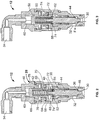
- the present multi-mode pressure relief valve 12 which is shown in the operating condition, is illustrated in FIG. 2 .
- the valve 12 is positioned in a branch line 26 along the adhesive flow path, between the pump 18 and the filter 20. In this manner, system 10 pressure is controlled by returning a portion or all of the fluid flow from the pump 18 back to the tank 12 through the discharge side branch line 27 from the valve 12.
- the valve 12 includes a valve body 28 having an adhesive inlet port 30 and an adhesive outlet port 32.
- the inlet and outlet 30, 32 are shown in transverse relation to each other, but it will be appreciated by those skilled in the art that the configuration of the inlet 30 and outlet 32 can be varied.
- An adhesive flow path F is defined between the inlet 30 and outlet 32.
- the valve 12 also includes a compressed gas (air) inlet 34 isolated from the adhesive inlet 30 and outlet 32.
- the body 28 thus defines an adhesive chamber 36 between the adhesive inlet 30 and outlet 32.
- a present body 28 is formed as two parts - a main body 38 and a cap 40 that are threaded together, with a seal 42 between the parts.
- a valve stem 44 is positioned in the body 28 to move into and out of the adhesive flow path F.
- a valve seat 46 is an annular element on which the stem 44 seats to permit or isolate the flow of adhesive. As seen in FIG. 2 , when the stem 44 moves off of the seat 46, flow of adhesive is established between the inlet 30 and the outlet 32.
- the stem 44 includes an annular recess 48 in which a spring 50 (described below) resides and which defines an annular shoulder 52.
- a stem guide 54 is positioned in the body 28 to guide the stem 44 as it moves between the open ( FIG. 1 ) and closed ( FIG. 3 ) positions.
- the guide 54 maintains the stem 44 positioned in the valve 12 and guides the stem 44 as it moves to open and close the valve 12.
- a stem seal 56 is positioned between the stem 44 and the guide 54 to prevent the flow of adhesive around the stem 44 and into the "clean" areas of the valve body 28.
- the seal 56 can be of the packed-type seal with a spring to assure good contact and isolation between the stem 44, the body 28 and guide 54.
- the valve 12 includes a piston 58 in the body 28, opposite of the seat 46.
- the spring 50 positioned between the piston 58 and stem 44.
- a compressed gas (or air) chamber 60 is defined between the air inlet 34 and a top 62 of the piston 58.
- the piston 58 is positioned to move within the air chamber 60 toward and away from the valve stem 44.
- the piston 58 is an inverted U-shaped or cup-shaped reciprocating member and includes a seal 64 to prevent the leakage of air around the periphery of the piston 58.
- a region around the cup-shaped portion 66 defines a piston face 68.
- the spring 50 is positioned between the stem 44 and the piston 58 and resides in the cup portion 66 of the piston 58.
- the spring 50 is held in place about the stem 44 by a post or finger 70 extending from the end of the stem 44, about which the spring 50 is positioned, and resides in the stem annular recess 48.
- the spring 50 is shown as a coil spring, those skilled in the art will appreciated that the spring can be of a number of different types, such as Belleville washers or the like and that such other constructions are within the scope of the present invention.
- a space 72 between the bottom of the piston 58 and the top of the valve stem 44 is open to the environs. In this manner, pressure either from the adhesive side (chamber 36) or air side (chamber 60) that may escape around their respective seals, does not adversely affect the operation of the valve, and does not influence the valve operation or function.
- valve 12 there is an adhesive-side 36 to air-side 60 pressure ratio of 14:1 at which the pressures are balanced. That is, for each 1 psi of air pressure the system provides 14 psi of adhesive pressure.
- the valve 12 ratio can, of course, be configured as desired for a particular adhesive system or control system.
- the valve 12 includes a piston stop surface 74 on the stem guide 54.
- the stop surface 74 prevents over travel of the piston 58 (see FIGS. 3 and 5 ) in the event that air pressure is greater than a maximum setting and to prevent shut-off when the adhesive pressure is greater than a minimum threshold. It provides a physical stop for movement of the piston 58.
- the valve 12 also includes a free clearance, indicated at 76, for zero-state operation (described in more detail below) relative to the normal or operating condition to allow the piston 58 to move fully up into the air chamber 60 (as seen in FIG. 4 ).
- the valve 12 has at least three and preferably four operating conditions or states.
- FIG. 2 shows the valve 12 in a normal operating condition. Adhesive pressure is exerted on the stem 44 urging the valve 12 open, while air pressure is exerted on the piston 58, urging the piston 58 and spring 50 to close the valve 12 (stem 44). The air pressure and adhesive pressure are in balance and the valve 12 remains open to permit the flow of adhesive.
- valve 12 When it is desired to de-pressurize the adhesive system 10 (to dump system pressure, for example, for system 10 maintenance), the valve 12 is in the zero-state condition as seen in FIG. 4 .
- the air pressure is reduced to or close to zero, and the piston 58 moves fully up in the body 28 toward the air inlet 34.
- the piston 58 moves into the free clearance or zero-state condition space 76 and rests against an upper piston stop 78 in the valve body 28.
- the stem 44 likewise moves up against a reduced spring 50 force to open the valve 12 and drops or dumps the pressure in the adhesive supply system 10.
- FIG. 5 illustrates a maximum operating condition.
- the air supply pressure is at a maximum with the piston 58 resting on the stop surface 74, and with the stem 44 being urged upward to open the valve 12 by fluid pressure on the stem 44.
- the stem 44 is spaced from the piston 58 (that is, there is no contact between the stem annular shoulder 52 and the piston face 68) and thus the stem 44 can move, as by adhesive pressure, up toward the piston 58 to allow adhesive flow, and/or to prevent over-pressurization with the stem 44 moving up, against the piston face 68, into the pressure relief condition.
- the present multi-mode valve 12 replaces three presently used valves, namely a pressure relief valve, a zero-state device (valve) and a line speed following valve.
- the present multi-mode valve 12 performs all three functions. That is, the zero-state condition is provided by isolating air flow to the valve 12, and thus allowing the valve 12 to go to full open; pressure relief is provided by allowing pressure against the stem 44, to open the valve 12, regardless of the air-side pressure 60 acting on the piston 58; and, line speed following is provided in the normal operating to maximum pressure conditions, by a balance of the air-side 60 pressure acting on the piston 58 and the counter-balancing adhesive-side 36 pressure acting on the valve stem 44.
- the present valve 12 advantageously provides these operating and safety modes in a single compact component with a minimum number of moving parts.
Landscapes
- Engineering & Computer Science (AREA)
- General Engineering & Computer Science (AREA)
- Mechanical Engineering (AREA)
- Safety Valves (AREA)
Applications Claiming Priority (2)
| Application Number | Priority Date | Filing Date | Title |
|---|---|---|---|
| US12/775,360 US8726934B2 (en) | 2010-05-06 | 2010-05-06 | Multi-mode pressure relief valve |
| PCT/US2011/031275 WO2011139464A1 (en) | 2010-05-06 | 2011-04-05 | Multi-mode pressure relief valve |
Publications (2)
| Publication Number | Publication Date |
|---|---|
| EP2567129A1 EP2567129A1 (en) | 2013-03-13 |
| EP2567129B1 true EP2567129B1 (en) | 2021-06-30 |
Family
ID=44303370
Family Applications (1)
| Application Number | Title | Priority Date | Filing Date |
|---|---|---|---|
| EP11715798.2A Active EP2567129B1 (en) | 2010-05-06 | 2011-04-05 | Multi-mode pressure relief valve |
Country Status (6)
| Country | Link |
|---|---|
| US (1) | US8726934B2 (enExample) |
| EP (1) | EP2567129B1 (enExample) |
| JP (1) | JP5864544B2 (enExample) |
| CN (1) | CN102884349B (enExample) |
| BR (1) | BR112012027663B1 (enExample) |
| WO (1) | WO2011139464A1 (enExample) |
Families Citing this family (6)
| Publication number | Priority date | Publication date | Assignee | Title |
|---|---|---|---|---|
| US9328835B2 (en) | 2012-10-23 | 2016-05-03 | Hamilton Sundstrand Corporation | High pressure relief valve piston |
| US10550945B2 (en) | 2013-04-25 | 2020-02-04 | Ohio University | Emergency shutdown valves with bypass features |
| US9708872B2 (en) | 2013-06-19 | 2017-07-18 | Wwt North America Holdings, Inc | Clean out sub |
| DE102013014673A1 (de) * | 2013-09-04 | 2015-03-05 | Hydac Fluidtechnik Gmbh | Lasthalteventil |
| WO2015143431A2 (en) * | 2014-03-21 | 2015-09-24 | Parker-Hannifin Corporation | Lubrication/bleeder fitting |
| CN112555474B (zh) * | 2020-12-03 | 2023-05-16 | 重庆红江机械有限责任公司 | 一种机械式滑油控制安全阀组件 |
Family Cites Families (18)
| Publication number | Priority date | Publication date | Assignee | Title |
|---|---|---|---|---|
| US1623431A (en) * | 1920-07-03 | 1927-04-05 | Vincen P Mcvoy | Combined cylinder cock and relief valve |
| DE664962C (de) | 1936-12-06 | 1938-09-13 | Schweizerische Lokomotiv | UEberdruckventil fuer die Druckmittelleitungen von OElschaltkupplungen |
| GB747667A (en) | 1953-03-19 | 1956-04-11 | Hindmarch Thomas | Pressure relief valve |
| US2944564A (en) * | 1959-05-29 | 1960-07-12 | Jr Thomas M Pettey | Pressure relief valve with remote calibration change |
| FR1561787A (enExample) | 1967-05-10 | 1969-03-28 | ||
| FR2343179A1 (fr) * | 1976-03-05 | 1977-09-30 | Poclain Sa | Clapet de decharge tare et dispositif de reglage a distance de tarages |
| EP0101523B1 (de) * | 1982-08-19 | 1986-04-16 | Vickers Systems GmbH | Druckbegrenzungsanordnung |
| JPH0731288Y2 (ja) * | 1989-03-10 | 1995-07-19 | 株式会社小松製作所 | 可変圧力制御弁 |
| JPH0475277U (enExample) * | 1990-11-09 | 1992-06-30 | ||
| US5651436A (en) * | 1995-04-20 | 1997-07-29 | Midwest Brake Bond Company | Brake and clutch control system |
| US5692537A (en) * | 1995-09-22 | 1997-12-02 | Western Atlas International, Inc. | Adjustable hydraulic control valve module |
| JPH1172172A (ja) * | 1997-06-20 | 1999-03-16 | Hitachi Constr Mach Co Ltd | バランスピストン型リリーフ弁 |
| US6318406B1 (en) * | 2000-03-14 | 2001-11-20 | Tyco Flow Control, Inc. | Pilot operated relief valve |
| US6837266B2 (en) * | 2002-03-25 | 2005-01-04 | Permco, Inc. | Remotely actuated multiple pressure direct acting relief valve |
| DE10312672A1 (de) * | 2003-02-26 | 2004-09-09 | Bosch Rexroth Ag | Direktgesteuertes Druckbegrenzungsventil |
| US6991000B2 (en) | 2003-05-20 | 2006-01-31 | Nordson Corporation | Manifold having integrated pressure relief valve |
| KR100764119B1 (ko) * | 2004-02-25 | 2007-10-08 | 볼보 컨스트럭션 이키프먼트 홀딩 스웨덴 에이비 | 파일럿 포펫형 릴리프 밸브 |
| CN2859143Y (zh) * | 2005-04-22 | 2007-01-17 | 郑银光 | 压力控制装置 |
-
2010
- 2010-05-06 US US12/775,360 patent/US8726934B2/en active Active
-
2011
- 2011-04-05 CN CN201180022546.1A patent/CN102884349B/zh active Active
- 2011-04-05 EP EP11715798.2A patent/EP2567129B1/en active Active
- 2011-04-05 WO PCT/US2011/031275 patent/WO2011139464A1/en not_active Ceased
- 2011-04-05 BR BR112012027663-8A patent/BR112012027663B1/pt active IP Right Grant
- 2011-04-05 JP JP2013509077A patent/JP5864544B2/ja active Active
Non-Patent Citations (1)
| Title |
|---|
| None * |
Also Published As
| Publication number | Publication date |
|---|---|
| EP2567129A1 (en) | 2013-03-13 |
| CN102884349B (zh) | 2015-02-25 |
| BR112012027663B1 (pt) | 2020-10-27 |
| WO2011139464A1 (en) | 2011-11-10 |
| US8726934B2 (en) | 2014-05-20 |
| JP2013525714A (ja) | 2013-06-20 |
| CN102884349A (zh) | 2013-01-16 |
| BR112012027663A2 (pt) | 2016-08-16 |
| US20110272044A1 (en) | 2011-11-10 |
| JP5864544B2 (ja) | 2016-02-17 |
Similar Documents
| Publication | Publication Date | Title |
|---|---|---|
| EP2567129B1 (en) | Multi-mode pressure relief valve | |
| EP2347158B1 (en) | Valves having removable internal actuation mechanisms | |
| RU2579427C2 (ru) | Устройство штока клапана и плунжера клапана для использования в регуляторах текучей среды | |
| CA2633009C (en) | Dome-loaded pressure regulator | |
| RU2558487C2 (ru) | Устройство для увеличения усиления привода с блокирующим устройством | |
| CA2917479A1 (en) | Internal relief valve apparatus for use with loading regulators | |
| WO2010005641A2 (en) | Pressure relief valves | |
| US4566476A (en) | Flow control device | |
| KR20090013239A (ko) | 유체 압력 조절기 | |
| WO2016003684A1 (en) | Ball valve and method of operating the same | |
| KR102242231B1 (ko) | 유량 제어 장치 및 유량 제어 장치의 유량 제어 방법 | |
| JP2013127317A (ja) | 自閉式停止弁に用いられる流れ制御アクチュエータ装置 | |
| KR101470310B1 (ko) | 수충격 방지용 밸브개폐장치 | |
| US20120000552A1 (en) | Fluid pressure control device | |
| EP3014167A2 (en) | A pressurised container valve | |
| WO2013033053A1 (en) | Hydraulic seal assembly for a thermoplastic material dispensing valve assembly | |
| CA3115433A1 (en) | Slam-shut safety assembly for providing redundant safety shutoff | |
| US6220280B1 (en) | Pilot operated relief valve with system isolating pilot valve from process media | |
| JP2007514159A (ja) | タンクに収容された液体又はダクトを流れる流体の圧力の検査装置 | |
| CN109931425B (zh) | 一种防漏排空装置 | |
| JP4336564B2 (ja) | リリーフ機構を備えた流量設定器 | |
| KR20180022957A (ko) | 밸브 장치 | |
| US20130146166A1 (en) | Auto shutoff device |
Legal Events
| Date | Code | Title | Description |
|---|---|---|---|
| PUAI | Public reference made under article 153(3) epc to a published international application that has entered the european phase |
Free format text: ORIGINAL CODE: 0009012 |
|
| 17P | Request for examination filed |
Effective date: 20121112 |
|
| AK | Designated contracting states |
Kind code of ref document: A1 Designated state(s): AL AT BE BG CH CY CZ DE DK EE ES FI FR GB GR HR HU IE IS IT LI LT LU LV MC MK MT NL NO PL PT RO RS SE SI SK SM TR |
|
| DAX | Request for extension of the european patent (deleted) | ||
| RAP1 | Party data changed (applicant data changed or rights of an application transferred) |
Owner name: ILLINOIS TOOL WORKS INC. |
|
| STAA | Information on the status of an ep patent application or granted ep patent |
Free format text: STATUS: EXAMINATION IS IN PROGRESS |
|
| RIN1 | Information on inventor provided before grant (corrected) |
Inventor name: BOLYARD, EDWARD, W. |
|
| 17Q | First examination report despatched |
Effective date: 20180322 |
|
| GRAP | Despatch of communication of intention to grant a patent |
Free format text: ORIGINAL CODE: EPIDOSNIGR1 |
|
| STAA | Information on the status of an ep patent application or granted ep patent |
Free format text: STATUS: GRANT OF PATENT IS INTENDED |
|
| INTG | Intention to grant announced |
Effective date: 20200731 |
|
| RIC1 | Information provided on ipc code assigned before grant |
Ipc: F16K 17/06 20060101AFI20200720BHEP Ipc: F16K 15/02 20060101ALI20200720BHEP |
|
| RIN1 | Information on inventor provided before grant (corrected) |
Inventor name: BOLYARD, EDWARD, W. |
|
| GRAJ | Information related to disapproval of communication of intention to grant by the applicant or resumption of examination proceedings by the epo deleted |
Free format text: ORIGINAL CODE: EPIDOSDIGR1 |
|
| STAA | Information on the status of an ep patent application or granted ep patent |
Free format text: STATUS: EXAMINATION IS IN PROGRESS |
|
| INTC | Intention to grant announced (deleted) | ||
| GRAP | Despatch of communication of intention to grant a patent |
Free format text: ORIGINAL CODE: EPIDOSNIGR1 |
|
| STAA | Information on the status of an ep patent application or granted ep patent |
Free format text: STATUS: GRANT OF PATENT IS INTENDED |
|
| INTG | Intention to grant announced |
Effective date: 20210120 |
|
| GRAS | Grant fee paid |
Free format text: ORIGINAL CODE: EPIDOSNIGR3 |
|
| GRAA | (expected) grant |
Free format text: ORIGINAL CODE: 0009210 |
|
| STAA | Information on the status of an ep patent application or granted ep patent |
Free format text: STATUS: THE PATENT HAS BEEN GRANTED |
|
| AK | Designated contracting states |
Kind code of ref document: B1 Designated state(s): AL AT BE BG CH CY CZ DE DK EE ES FI FR GB GR HR HU IE IS IT LI LT LU LV MC MK MT NL NO PL PT RO RS SE SI SK SM TR |
|
| REG | Reference to a national code |
Ref country code: GB Ref legal event code: FG4D Ref country code: CH Ref legal event code: EP |
|
| REG | Reference to a national code |
Ref country code: AT Ref legal event code: REF Ref document number: 1406638 Country of ref document: AT Kind code of ref document: T Effective date: 20210715 |
|
| REG | Reference to a national code |
Ref country code: DE Ref legal event code: R096 Ref document number: 602011071270 Country of ref document: DE |
|
| REG | Reference to a national code |
Ref country code: IE Ref legal event code: FG4D |
|
| REG | Reference to a national code |
Ref country code: LT Ref legal event code: MG9D |
|
| PG25 | Lapsed in a contracting state [announced via postgrant information from national office to epo] |
Ref country code: FI Free format text: LAPSE BECAUSE OF FAILURE TO SUBMIT A TRANSLATION OF THE DESCRIPTION OR TO PAY THE FEE WITHIN THE PRESCRIBED TIME-LIMIT Effective date: 20210630 Ref country code: BG Free format text: LAPSE BECAUSE OF FAILURE TO SUBMIT A TRANSLATION OF THE DESCRIPTION OR TO PAY THE FEE WITHIN THE PRESCRIBED TIME-LIMIT Effective date: 20210930 Ref country code: HR Free format text: LAPSE BECAUSE OF FAILURE TO SUBMIT A TRANSLATION OF THE DESCRIPTION OR TO PAY THE FEE WITHIN THE PRESCRIBED TIME-LIMIT Effective date: 20210630 |
|
| REG | Reference to a national code |
Ref country code: NL Ref legal event code: MP Effective date: 20210630 |
|
| REG | Reference to a national code |
Ref country code: AT Ref legal event code: MK05 Ref document number: 1406638 Country of ref document: AT Kind code of ref document: T Effective date: 20210630 |
|
| PG25 | Lapsed in a contracting state [announced via postgrant information from national office to epo] |
Ref country code: LV Free format text: LAPSE BECAUSE OF FAILURE TO SUBMIT A TRANSLATION OF THE DESCRIPTION OR TO PAY THE FEE WITHIN THE PRESCRIBED TIME-LIMIT Effective date: 20210630 Ref country code: GR Free format text: LAPSE BECAUSE OF FAILURE TO SUBMIT A TRANSLATION OF THE DESCRIPTION OR TO PAY THE FEE WITHIN THE PRESCRIBED TIME-LIMIT Effective date: 20211001 Ref country code: RS Free format text: LAPSE BECAUSE OF FAILURE TO SUBMIT A TRANSLATION OF THE DESCRIPTION OR TO PAY THE FEE WITHIN THE PRESCRIBED TIME-LIMIT Effective date: 20210630 Ref country code: SE Free format text: LAPSE BECAUSE OF FAILURE TO SUBMIT A TRANSLATION OF THE DESCRIPTION OR TO PAY THE FEE WITHIN THE PRESCRIBED TIME-LIMIT Effective date: 20210630 Ref country code: NO Free format text: LAPSE BECAUSE OF FAILURE TO SUBMIT A TRANSLATION OF THE DESCRIPTION OR TO PAY THE FEE WITHIN THE PRESCRIBED TIME-LIMIT Effective date: 20210930 |
|
| PG25 | Lapsed in a contracting state [announced via postgrant information from national office to epo] |
Ref country code: SK Free format text: LAPSE BECAUSE OF FAILURE TO SUBMIT A TRANSLATION OF THE DESCRIPTION OR TO PAY THE FEE WITHIN THE PRESCRIBED TIME-LIMIT Effective date: 20210630 Ref country code: SM Free format text: LAPSE BECAUSE OF FAILURE TO SUBMIT A TRANSLATION OF THE DESCRIPTION OR TO PAY THE FEE WITHIN THE PRESCRIBED TIME-LIMIT Effective date: 20210630 Ref country code: EE Free format text: LAPSE BECAUSE OF FAILURE TO SUBMIT A TRANSLATION OF THE DESCRIPTION OR TO PAY THE FEE WITHIN THE PRESCRIBED TIME-LIMIT Effective date: 20210630 Ref country code: CZ Free format text: LAPSE BECAUSE OF FAILURE TO SUBMIT A TRANSLATION OF THE DESCRIPTION OR TO PAY THE FEE WITHIN THE PRESCRIBED TIME-LIMIT Effective date: 20210630 Ref country code: ES Free format text: LAPSE BECAUSE OF FAILURE TO SUBMIT A TRANSLATION OF THE DESCRIPTION OR TO PAY THE FEE WITHIN THE PRESCRIBED TIME-LIMIT Effective date: 20210630 Ref country code: PT Free format text: LAPSE BECAUSE OF FAILURE TO SUBMIT A TRANSLATION OF THE DESCRIPTION OR TO PAY THE FEE WITHIN THE PRESCRIBED TIME-LIMIT Effective date: 20211102 Ref country code: NL Free format text: LAPSE BECAUSE OF FAILURE TO SUBMIT A TRANSLATION OF THE DESCRIPTION OR TO PAY THE FEE WITHIN THE PRESCRIBED TIME-LIMIT Effective date: 20210630 Ref country code: RO Free format text: LAPSE BECAUSE OF FAILURE TO SUBMIT A TRANSLATION OF THE DESCRIPTION OR TO PAY THE FEE WITHIN THE PRESCRIBED TIME-LIMIT Effective date: 20210630 Ref country code: AT Free format text: LAPSE BECAUSE OF FAILURE TO SUBMIT A TRANSLATION OF THE DESCRIPTION OR TO PAY THE FEE WITHIN THE PRESCRIBED TIME-LIMIT Effective date: 20210630 |
|
| PG25 | Lapsed in a contracting state [announced via postgrant information from national office to epo] |
Ref country code: PL Free format text: LAPSE BECAUSE OF FAILURE TO SUBMIT A TRANSLATION OF THE DESCRIPTION OR TO PAY THE FEE WITHIN THE PRESCRIBED TIME-LIMIT Effective date: 20210630 |
|
| REG | Reference to a national code |
Ref country code: DE Ref legal event code: R097 Ref document number: 602011071270 Country of ref document: DE |
|
| PG25 | Lapsed in a contracting state [announced via postgrant information from national office to epo] |
Ref country code: DK Free format text: LAPSE BECAUSE OF FAILURE TO SUBMIT A TRANSLATION OF THE DESCRIPTION OR TO PAY THE FEE WITHIN THE PRESCRIBED TIME-LIMIT Effective date: 20210630 |
|
| PLBE | No opposition filed within time limit |
Free format text: ORIGINAL CODE: 0009261 |
|
| STAA | Information on the status of an ep patent application or granted ep patent |
Free format text: STATUS: NO OPPOSITION FILED WITHIN TIME LIMIT |
|
| PG25 | Lapsed in a contracting state [announced via postgrant information from national office to epo] |
Ref country code: AL Free format text: LAPSE BECAUSE OF FAILURE TO SUBMIT A TRANSLATION OF THE DESCRIPTION OR TO PAY THE FEE WITHIN THE PRESCRIBED TIME-LIMIT Effective date: 20210630 |
|
| 26N | No opposition filed |
Effective date: 20220331 |
|
| REG | Reference to a national code |
Ref country code: CH Ref legal event code: PL |
|
| REG | Reference to a national code |
Ref country code: BE Ref legal event code: MM Effective date: 20220430 |
|
| PG25 | Lapsed in a contracting state [announced via postgrant information from national office to epo] |
Ref country code: MC Free format text: LAPSE BECAUSE OF FAILURE TO SUBMIT A TRANSLATION OF THE DESCRIPTION OR TO PAY THE FEE WITHIN THE PRESCRIBED TIME-LIMIT Effective date: 20210630 Ref country code: LU Free format text: LAPSE BECAUSE OF NON-PAYMENT OF DUE FEES Effective date: 20220405 Ref country code: LI Free format text: LAPSE BECAUSE OF NON-PAYMENT OF DUE FEES Effective date: 20220430 Ref country code: CH Free format text: LAPSE BECAUSE OF NON-PAYMENT OF DUE FEES Effective date: 20220430 |
|
| PG25 | Lapsed in a contracting state [announced via postgrant information from national office to epo] |
Ref country code: BE Free format text: LAPSE BECAUSE OF NON-PAYMENT OF DUE FEES Effective date: 20220430 |
|
| PG25 | Lapsed in a contracting state [announced via postgrant information from national office to epo] |
Ref country code: LT Free format text: LAPSE BECAUSE OF FAILURE TO SUBMIT A TRANSLATION OF THE DESCRIPTION OR TO PAY THE FEE WITHIN THE PRESCRIBED TIME-LIMIT Effective date: 20210630 Ref country code: IE Free format text: LAPSE BECAUSE OF NON-PAYMENT OF DUE FEES Effective date: 20220405 |
|
| P01 | Opt-out of the competence of the unified patent court (upc) registered |
Effective date: 20230606 |
|
| PG25 | Lapsed in a contracting state [announced via postgrant information from national office to epo] |
Ref country code: HU Free format text: LAPSE BECAUSE OF FAILURE TO SUBMIT A TRANSLATION OF THE DESCRIPTION OR TO PAY THE FEE WITHIN THE PRESCRIBED TIME-LIMIT; INVALID AB INITIO Effective date: 20110405 |
|
| PG25 | Lapsed in a contracting state [announced via postgrant information from national office to epo] |
Ref country code: MK Free format text: LAPSE BECAUSE OF FAILURE TO SUBMIT A TRANSLATION OF THE DESCRIPTION OR TO PAY THE FEE WITHIN THE PRESCRIBED TIME-LIMIT Effective date: 20210630 Ref country code: CY Free format text: LAPSE BECAUSE OF FAILURE TO SUBMIT A TRANSLATION OF THE DESCRIPTION OR TO PAY THE FEE WITHIN THE PRESCRIBED TIME-LIMIT Effective date: 20210630 |
|
| PG25 | Lapsed in a contracting state [announced via postgrant information from national office to epo] |
Ref country code: TR Free format text: LAPSE BECAUSE OF FAILURE TO SUBMIT A TRANSLATION OF THE DESCRIPTION OR TO PAY THE FEE WITHIN THE PRESCRIBED TIME-LIMIT Effective date: 20210630 |
|
| PG25 | Lapsed in a contracting state [announced via postgrant information from national office to epo] |
Ref country code: MT Free format text: LAPSE BECAUSE OF FAILURE TO SUBMIT A TRANSLATION OF THE DESCRIPTION OR TO PAY THE FEE WITHIN THE PRESCRIBED TIME-LIMIT Effective date: 20210630 |
|
| PGFP | Annual fee paid to national office [announced via postgrant information from national office to epo] |
Ref country code: DE Payment date: 20250429 Year of fee payment: 15 |
|
| PGFP | Annual fee paid to national office [announced via postgrant information from national office to epo] |
Ref country code: GB Payment date: 20250428 Year of fee payment: 15 |
|
| PGFP | Annual fee paid to national office [announced via postgrant information from national office to epo] |
Ref country code: IT Payment date: 20250422 Year of fee payment: 15 |
|
| PGFP | Annual fee paid to national office [announced via postgrant information from national office to epo] |
Ref country code: FR Payment date: 20250425 Year of fee payment: 15 |