EP2567129B1 - Multi-mode pressure relief valve - Google Patents
Multi-mode pressure relief valve Download PDFInfo
- Publication number
- EP2567129B1 EP2567129B1 EP11715798.2A EP11715798A EP2567129B1 EP 2567129 B1 EP2567129 B1 EP 2567129B1 EP 11715798 A EP11715798 A EP 11715798A EP 2567129 B1 EP2567129 B1 EP 2567129B1
- Authority
- EP
- European Patent Office
- Prior art keywords
- piston
- valve
- valve stem
- pressure
- stem
- Prior art date
- Legal status (The legal status is an assumption and is not a legal conclusion. Google has not performed a legal analysis and makes no representation as to the accuracy of the status listed.)
- Active
Links
- 239000012530 fluid Substances 0.000 claims description 30
- 238000004891 communication Methods 0.000 claims description 5
- 239000000853 adhesive Substances 0.000 description 50
- 230000001070 adhesive effect Effects 0.000 description 50
- 238000004519 manufacturing process Methods 0.000 description 7
- 238000012423 maintenance Methods 0.000 description 4
- 239000004831 Hot glue Substances 0.000 description 3
- 230000008901 benefit Effects 0.000 description 3
- 230000002411 adverse Effects 0.000 description 2
- 235000015496 breakfast cereal Nutrition 0.000 description 2
- 238000000034 method Methods 0.000 description 2
- 238000012986 modification Methods 0.000 description 2
- 230000004048 modification Effects 0.000 description 2
- 238000010276 construction Methods 0.000 description 1
- 230000000694 effects Effects 0.000 description 1
- 239000003292 glue Substances 0.000 description 1
- 239000012943 hotmelt Substances 0.000 description 1
- 238000009434 installation Methods 0.000 description 1
- 238000002955 isolation Methods 0.000 description 1
- 230000007935 neutral effect Effects 0.000 description 1
- 238000012354 overpressurization Methods 0.000 description 1
- 238000004806 packaging method and process Methods 0.000 description 1
- 230000008569 process Effects 0.000 description 1
- 230000008439 repair process Effects 0.000 description 1
- 230000000284 resting effect Effects 0.000 description 1
- 238000012360 testing method Methods 0.000 description 1
Images


Classifications
-
- F—MECHANICAL ENGINEERING; LIGHTING; HEATING; WEAPONS; BLASTING
- F16—ENGINEERING ELEMENTS AND UNITS; GENERAL MEASURES FOR PRODUCING AND MAINTAINING EFFECTIVE FUNCTIONING OF MACHINES OR INSTALLATIONS; THERMAL INSULATION IN GENERAL
- F16K—VALVES; TAPS; COCKS; ACTUATING-FLOATS; DEVICES FOR VENTING OR AERATING
- F16K15/00—Check valves
- F16K15/02—Check valves with guided rigid valve members
- F16K15/025—Check valves with guided rigid valve members the valve being loaded by a spring
-
- F—MECHANICAL ENGINEERING; LIGHTING; HEATING; WEAPONS; BLASTING
- F16—ENGINEERING ELEMENTS AND UNITS; GENERAL MEASURES FOR PRODUCING AND MAINTAINING EFFECTIVE FUNCTIONING OF MACHINES OR INSTALLATIONS; THERMAL INSULATION IN GENERAL
- F16K—VALVES; TAPS; COCKS; ACTUATING-FLOATS; DEVICES FOR VENTING OR AERATING
- F16K17/00—Safety valves; Equalising valves, e.g. pressure relief valves
- F16K17/02—Safety valves; Equalising valves, e.g. pressure relief valves opening on surplus pressure on one side; closing on insufficient pressure on one side
- F16K17/04—Safety valves; Equalising valves, e.g. pressure relief valves opening on surplus pressure on one side; closing on insufficient pressure on one side spring-loaded
- F16K17/06—Safety valves; Equalising valves, e.g. pressure relief valves opening on surplus pressure on one side; closing on insufficient pressure on one side spring-loaded with special arrangements for adjusting the opening pressure
- F16K17/065—Safety valves; Equalising valves, e.g. pressure relief valves opening on surplus pressure on one side; closing on insufficient pressure on one side spring-loaded with special arrangements for adjusting the opening pressure with differential piston
-
- B—PERFORMING OPERATIONS; TRANSPORTING
- B05—SPRAYING OR ATOMISING IN GENERAL; APPLYING FLUENT MATERIALS TO SURFACES, IN GENERAL
- B05C—APPARATUS FOR APPLYING FLUENT MATERIALS TO SURFACES, IN GENERAL
- B05C5/00—Apparatus in which liquid or other fluent material is projected, poured or allowed to flow on to the surface of the work
- B05C5/02—Apparatus in which liquid or other fluent material is projected, poured or allowed to flow on to the surface of the work the liquid or other fluent material being discharged through an outlet orifice by pressure, e.g. from an outlet device in contact or almost in contact, with the work
-
- Y—GENERAL TAGGING OF NEW TECHNOLOGICAL DEVELOPMENTS; GENERAL TAGGING OF CROSS-SECTIONAL TECHNOLOGIES SPANNING OVER SEVERAL SECTIONS OF THE IPC; TECHNICAL SUBJECTS COVERED BY FORMER USPC CROSS-REFERENCE ART COLLECTIONS [XRACs] AND DIGESTS
- Y10—TECHNICAL SUBJECTS COVERED BY FORMER USPC
- Y10T—TECHNICAL SUBJECTS COVERED BY FORMER US CLASSIFICATION
- Y10T137/00—Fluid handling
- Y10T137/7722—Line condition change responsive valves
- Y10T137/7758—Pilot or servo controlled
- Y10T137/7762—Fluid pressure type
- Y10T137/7769—Single acting fluid servo
- Y10T137/777—Spring biased
-
- Y—GENERAL TAGGING OF NEW TECHNOLOGICAL DEVELOPMENTS; GENERAL TAGGING OF CROSS-SECTIONAL TECHNOLOGIES SPANNING OVER SEVERAL SECTIONS OF THE IPC; TECHNICAL SUBJECTS COVERED BY FORMER USPC CROSS-REFERENCE ART COLLECTIONS [XRACs] AND DIGESTS
- Y10—TECHNICAL SUBJECTS COVERED BY FORMER USPC
- Y10T—TECHNICAL SUBJECTS COVERED BY FORMER US CLASSIFICATION
- Y10T137/00—Fluid handling
- Y10T137/7722—Line condition change responsive valves
- Y10T137/7837—Direct response valves [i.e., check valve type]
- Y10T137/7904—Reciprocating valves
- Y10T137/7905—Plural biasing means
-
- Y—GENERAL TAGGING OF NEW TECHNOLOGICAL DEVELOPMENTS; GENERAL TAGGING OF CROSS-SECTIONAL TECHNOLOGIES SPANNING OVER SEVERAL SECTIONS OF THE IPC; TECHNICAL SUBJECTS COVERED BY FORMER USPC CROSS-REFERENCE ART COLLECTIONS [XRACs] AND DIGESTS
- Y10—TECHNICAL SUBJECTS COVERED BY FORMER USPC
- Y10T—TECHNICAL SUBJECTS COVERED BY FORMER US CLASSIFICATION
- Y10T137/00—Fluid handling
- Y10T137/7722—Line condition change responsive valves
- Y10T137/7837—Direct response valves [i.e., check valve type]
- Y10T137/7904—Reciprocating valves
- Y10T137/7922—Spring biased
- Y10T137/7923—With means to protect spring from fluid
-
- Y—GENERAL TAGGING OF NEW TECHNOLOGICAL DEVELOPMENTS; GENERAL TAGGING OF CROSS-SECTIONAL TECHNOLOGIES SPANNING OVER SEVERAL SECTIONS OF THE IPC; TECHNICAL SUBJECTS COVERED BY FORMER USPC CROSS-REFERENCE ART COLLECTIONS [XRACs] AND DIGESTS
- Y10—TECHNICAL SUBJECTS COVERED BY FORMER USPC
- Y10T—TECHNICAL SUBJECTS COVERED BY FORMER US CLASSIFICATION
- Y10T137/00—Fluid handling
- Y10T137/7722—Line condition change responsive valves
- Y10T137/7837—Direct response valves [i.e., check valve type]
- Y10T137/7904—Reciprocating valves
- Y10T137/7922—Spring biased
- Y10T137/7929—Spring coaxial with valve
Landscapes
- Engineering & Computer Science (AREA)
- General Engineering & Computer Science (AREA)
- Mechanical Engineering (AREA)
- Safety Valves (AREA)
Description
- The present invention relates to a multi-mode valve. More particularly, the present invention relates to a multi-mode pressure relief valve for use in pressurized hot-melt adhesive systems.
- Pressurized hot-melt adhesive systems are in use in a multitude of production facilities, in countless industries. For example, these system are used to seal cartons and containers for commercial products ranging from soda-pop to breakfast cereals to tools and consumables.
- In pressurized hot-melt systems a pressure relief valve is provided to protect against failure of the equipment in the event of an abnormally high pressure situation. Typically this protection is provided by a mechanical pressure relief valve that vents high pressure to the tank or reservoir that supplies the adhesive.
- It is also desirable to have the ability to quickly reduce the pressure within the system to a zero-pressure condition (known as zero-state). This is desirable for maintenance of the system, for emergency-stop situations, or the like. A mechanical pressure relief is not suitable for this purpose. As such, a separate pneumatic actuated valve is often provided for this function. Pneumatic operation allows the valve to be quickly deenergized to reduce system pressure. This, however, requires the use of a pneumatic circuit, actuator and other components.
- Further, in some installations it is desirable to have the ability to adjust the adhesive pressure curve to match production speed requirements. This function maybe provided by a separate mechanical adhesive bypass valve, and/or by adjusting the pump speed dynamically with the parent machine line speed.
- While this method functions well, often the adhesive pressure cannot be reduced quickly enough during a parent machine line stop. The result is excessive glue application on the final products.
- As will be understood, each of these functions requires the use of a separate valve. These individual components each require maintenance, testing and the like in order to assure that they function properly. In addition, there is an initial capital cost associated with each. And, if a single component requires repair (or maintenance), it can adversely affect operation, not only of the adhesive system but of the parent line operation.
- Accordingly, there is a need to reduce the number of components (valves) needed to carry out the pressure relief, zero-state and line speed following functions in a holt-melt adhesive application system. Desirably, such a valve has minimal moving parts. More desirably, such a valve is controlled by the pneumatic circuit of the adhesive system in which it is installed.
-
GB 747,667 DE 664,962 ,FR 1561787 EP 1479955 each disclose a pressure relief valve having an adjustable relief pressure controlled by a pneumatically- or hydraulically-operated piston. - In accordance with the present invention, there is provided a multi-mode pressure relief valve defined in the accompanying claims. A multi-mode pressure relief valve carries out the pressure relief, zero-state and line speed following functions in a holt-melt adhesive application system. The valve has minimal moving parts and is preferably controlled by the pneumatic circuit of the adhesive system in which it is installed.
- The valve has a body having a fluid inlet port and a fluid outlet port that define a fluid chamber. The body includes a seat at the fluid chamber between the inlet port and the outlet port. The body further includes a compressed gas inlet port and defines a compressed gas chamber in flow communication with the gas inlet port. The compressed gas chamber and the fluid chamber are isolated from one another.
- A piston is disposed in the compressed gas chamber and is configured for reciprocating movement in the chamber. The piston has a spring receiving region.
- A valve stem is movable within the fluid chamber between an open condition in which flow communication is established between the inlet port and the outlet port and a closed position to stop flow through the valve. The valve stem has a spring receiving region.
- A spring, such as a coil spring, is disposed between the valve stem and the piston. The spring urges the piston into the compressed gas chamber toward the gas inlet and urges the valve stem into the fluid chamber to the closed position.
- The valve is operable in at least three modes. In an operating mode, the valve is in the open condition, the valve stem is spaced from the piston, and the piston applies a pressure on the valve stem, through the spring. The piston pressure is balanced by fluid pressure exerting a force on the valve stem.
- In a zero-state mode, the valve is in the open condition, the valve stem is spaced from the piston and the spring is in a relaxed state. The piston applies no pressure on the valve stem.
- And, in a relief mode, the valve stem is in the open condition with the valve stem contacting the piston. The spring is in a compressed state due to the fluid pressure of fluid entering the inlet exerting a force on the valve stem and gas pressure on the piston.
- The valve body defines a space between the piston and the valve stem. The space is open to the environs to prevent influence from the compressed gas or the fluid on the valve operation or function.
- In a present valve, the piston has a piston face opposing the valve stem and the valve stem includes a shoulder portion for contacting the piston face when the valve is in the relief mode. The valve includes a piston stop surface that prevents the piston face from contacting the valve stem shoulder portion when in the operating mode and the zero state mode.
- A stem guide is annularly disposed about the valve stem, positioned in the valve body. The piston stop surface is formed on the stem guide.
- The valve can also operate in a maximum pressure mode, which is an operating state, in which the valve stem may be in the open condition, the valve stem is spaced from the piston, and the piston face rests on the piston stop surface. The piston applies a pressure on the valve stem through the spring and the valve stem shoulder portion is spaced from the piston face.
- The spring is disposed, at least in part in the space. The piston can be cup-shaped, with the spring receiving region positioned in the cup.
- The valve includes a valve seat in the fluid chamber between the fluid inlet port and the fluid outlet port. The stem engages the seat to close the valve.
- These and other features and advantages of the present invention will be apparent from the following detailed description, in conjunction with the appended claims.
- The benefits and advantages of the present invention will become more readily apparent to those of ordinary skill in the relevant art after reviewing the following detailed description and accompanying drawings, wherein:
-
FIG. 1 is a schematic illustration of an adhesive system having a multi-mode pressure relief valve embodying the principles of the present invention; -
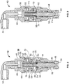
FIG. 2 is a cross-sectional view of the valve in the neutral or operating condition; -
FIG. 3 is a cross-sectional view of the valve in the maximum pressure relief condition; -
FIG. 4 is a cross-sectional view of the valve in the zero-state condition; and -
FIG. 5 is a cross-sectional view of the valve in the maximum pressure condition. - While the present invention is susceptible of embodiment in various forms, there are shown in the drawings and will hereinafter be described several preferred embodiments with the understanding that the present disclosure is to be considered an exemplification of the invention and is not intended to limit the invention to the specific embodiments illustrated.
- It should be further understood that the title of this section of the specification, namely, "Detailed Description of the Invention," relates to a requirement of the United States Patent and Trademark Office, and does not imply, nor should be inferred to limit the subject matter disclosed herein.
- Referring now to the figures and in particular to
FIG. 1 , there is shown a schematic illustration of a hot meltadhesive system 10 having a multi-modepressure relief valve 12 in accordance with the principles of the present invention. Theadhesive system 10 includes an adhesive supply, such at the illustratedtank 14, which contains a specified volume of adhesive maintained at a temperature that allows for transport or conveyance of the adhesive. In a typical operation, the tank temperature is maintained about 50°F lower than the adhesive application temperature. A present system has the tank temperature maintained at about 300°F. - An
adhesive dispenser head 16, four shown, heats the adhesive to an operating or application temperature (for example, about 350°F) at which the adhesive is discharged onto the desired object. It will be appreciated that the object can be, for example, a carton or container for commercial products ranging from soda-pop to breakfast cereals to tools and consumables. The adhesive is dispensed at the desired temperature and at a desired flow rate to control the application of the adhesive to the object. The flow rate is determined so that the adhesive flows onto the object without affecting or slowing the production line speed, but is applied in a sufficient volume to effect the adhesive process. - A
pump 18 supplies the adhesive to the applicator heads 16. In present systems, the adhesive is supplied at relatively high pressures, as high as 1000-1100 psi. Afilter 20 can be provided to filter the adhesive prior to routing to the applicator heads 16, and various pressure and temperature monitors 22 can be provided in thesystem 10. - The overall operation of the production line (not shown) and the
adhesive system 10 is carried out using a pneumatic control system, pneumatic supply being shown generally at 24. Such systems are sufficiently versatile to allow for controlling the valves needed for operation, as well the other components within the system. In certain production line systems, the pressure of the pneumatic system is used to control the overall production (packaging) operation. In these system, the speed of production is controlled by thepneumatic system 24 pressure. - The present multi-mode
pressure relief valve 12, which is shown in the operating condition, is illustrated inFIG. 2 . Referring briefly again toFIG. 1 , thevalve 12 is positioned in abranch line 26 along the adhesive flow path, between thepump 18 and thefilter 20. In this manner,system 10 pressure is controlled by returning a portion or all of the fluid flow from thepump 18 back to thetank 12 through the dischargeside branch line 27 from thevalve 12. - Referring back to
FIG. 2 , thevalve 12 includes avalve body 28 having anadhesive inlet port 30 and anadhesive outlet port 32. The inlet andoutlet inlet 30 andoutlet 32 can be varied. An adhesive flow path F is defined between theinlet 30 andoutlet 32. Thevalve 12 also includes a compressed gas (air)inlet 34 isolated from theadhesive inlet 30 andoutlet 32. Thebody 28 thus defines anadhesive chamber 36 between theadhesive inlet 30 andoutlet 32. Apresent body 28 is formed as two parts - amain body 38 and acap 40 that are threaded together, with aseal 42 between the parts. - A
valve stem 44 is positioned in thebody 28 to move into and out of the adhesive flow path F. Avalve seat 46 is an annular element on which thestem 44 seats to permit or isolate the flow of adhesive. As seen inFIG. 2 , when thestem 44 moves off of theseat 46, flow of adhesive is established between theinlet 30 and theoutlet 32. Thestem 44 includes anannular recess 48 in which a spring 50 (described below) resides and which defines anannular shoulder 52. - A
stem guide 54 is positioned in thebody 28 to guide thestem 44 as it moves between the open (FIG. 1 ) and closed (FIG. 3 ) positions. Theguide 54 maintains thestem 44 positioned in thevalve 12 and guides thestem 44 as it moves to open and close thevalve 12. Astem seal 56 is positioned between thestem 44 and theguide 54 to prevent the flow of adhesive around thestem 44 and into the "clean" areas of thevalve body 28. Theseal 56 can be of the packed-type seal with a spring to assure good contact and isolation between thestem 44, thebody 28 andguide 54. - The
valve 12 includes apiston 58 in thebody 28, opposite of theseat 46. Thespring 50 positioned between thepiston 58 andstem 44. A compressed gas (or air)chamber 60 is defined between theair inlet 34 and a top 62 of thepiston 58. Thepiston 58 is positioned to move within theair chamber 60 toward and away from thevalve stem 44. Thepiston 58 is an inverted U-shaped or cup-shaped reciprocating member and includes aseal 64 to prevent the leakage of air around the periphery of thepiston 58. A region around the cup-shapedportion 66 defines apiston face 68. - The
spring 50 is positioned between thestem 44 and thepiston 58 and resides in thecup portion 66 of thepiston 58. Thespring 50 is held in place about thestem 44 by a post orfinger 70 extending from the end of thestem 44, about which thespring 50 is positioned, and resides in the stemannular recess 48. Although thespring 50 is shown as a coil spring, those skilled in the art will appreciated that the spring can be of a number of different types, such as Belleville washers or the like and that such other constructions are within the scope of the present invention. Aspace 72 between the bottom of thepiston 58 and the top of thevalve stem 44 is open to the environs. In this manner, pressure either from the adhesive side (chamber 36) or air side (chamber 60) that may escape around their respective seals, does not adversely affect the operation of the valve, and does not influence the valve operation or function. - It will be appreciated from a study of the figures that the force exerted on the
piston 58 from the air-side 60 pressure, in conjunction with thespring 50 force, counteracts or balances the force exerted on the valve stem 44 from theadhesive side 36 pressure. In apresent valve 12, there is an adhesive-side 36 to air-side 60 pressure ratio of 14:1 at which the pressures are balanced. That is, for each 1 psi of air pressure the system provides 14 psi of adhesive pressure. Thevalve 12 ratio can, of course, be configured as desired for a particular adhesive system or control system. - Various other features of the valve have been included to achieve desired operating characteristics. As best seen in
FIG. 2 , thevalve 12 includes apiston stop surface 74 on thestem guide 54. Thestop surface 74 prevents over travel of the piston 58 (seeFIGS. 3 and5 ) in the event that air pressure is greater than a maximum setting and to prevent shut-off when the adhesive pressure is greater than a minimum threshold. It provides a physical stop for movement of thepiston 58. Referring toFIG. 2 , thevalve 12 also includes a free clearance, indicated at 76, for zero-state operation (described in more detail below) relative to the normal or operating condition to allow thepiston 58 to move fully up into the air chamber 60 (as seen inFIG. 4 ). - The
valve 12 has at least three and preferably four operating conditions or states.FIG. 2 shows thevalve 12 in a normal operating condition. Adhesive pressure is exerted on thestem 44 urging thevalve 12 open, while air pressure is exerted on thepiston 58, urging thepiston 58 andspring 50 to close the valve 12 (stem 44). The air pressure and adhesive pressure are in balance and thevalve 12 remains open to permit the flow of adhesive. - When it is desired to relieve the pressure in the
adhesive system 10, as when the pump discharge pressure is too high, or for example, in a high pressure fault condition, the upward force on thevalve stem 44 will urge thestem 44 up to open thevalve 12, regardless of the air pressure in thesystem 10. This pressure relief condition is shown inFIG. 3 , in which thepiston 58 is shown at maximum air pressure, but the force on the stem 44 (and spring 50) urges thevalve 12 open nevertheless. Even with the high air pressure, it can be seen that thepiston stop surface 74 prevents overtravel of thepiston 58 and allows thestem 44 to rise and thevalve 12 to open. In this condition, the pistonannular shoulder 52 is in contact with thepiston face 68 and thevalve 12 is open even though thepiston 58 is at a maximum downward position. That is, even with thepiston 58 subjected to maximum air-side 60 pressure, there is sufficient physical space between theannular shoulder 52 and thepiston face 68 to allow thestem 44 to rise (until theshoulder 52 contacts the face 68) to relievesystem 10 pressure. - When it is desired to de-pressurize the adhesive system 10 (to dump system pressure, for example, for
system 10 maintenance), thevalve 12 is in the zero-state condition as seen inFIG. 4 . Here, the air pressure is reduced to or close to zero, and thepiston 58 moves fully up in thebody 28 toward theair inlet 34. In this condition, thepiston 58 moves into the free clearance or zero-state condition space 76 and rests against anupper piston stop 78 in thevalve body 28. Thus, thestem 44 likewise moves up against a reducedspring 50 force to open thevalve 12 and drops or dumps the pressure in theadhesive supply system 10. - A last operating condition is shown in
FIG. 5 which illustrates a maximum operating condition. Here, the air supply pressure is at a maximum with thepiston 58 resting on thestop surface 74, and with thestem 44 being urged upward to open thevalve 12 by fluid pressure on thestem 44. Thestem 44 is spaced from the piston 58 (that is, there is no contact between the stemannular shoulder 52 and the piston face 68) and thus thestem 44 can move, as by adhesive pressure, up toward thepiston 58 to allow adhesive flow, and/or to prevent over-pressurization with thestem 44 moving up, against thepiston face 68, into the pressure relief condition. - As set forth above, the present
multi-mode valve 12 replaces three presently used valves, namely a pressure relief valve, a zero-state device (valve) and a line speed following valve. The presentmulti-mode valve 12 performs all three functions. That is, the zero-state condition is provided by isolating air flow to thevalve 12, and thus allowing thevalve 12 to go to full open; pressure relief is provided by allowing pressure against thestem 44, to open thevalve 12, regardless of the air-side pressure 60 acting on thepiston 58; and, line speed following is provided in the normal operating to maximum pressure conditions, by a balance of the air-side 60 pressure acting on thepiston 58 and the counter-balancing adhesive-side 36 pressure acting on thevalve stem 44. Moreover, thepresent valve 12 advantageously provides these operating and safety modes in a single compact component with a minimum number of moving parts. - In the present disclosure, the words "a" or "an" are to be taken to include both the singular and the plural. Conversely, any reference to plural items shall, where appropriate, include the singular. All patents referred to herein, are hereby incorporated herein by reference, whether or not specifically done so within the text of this disclosure.
- From the foregoing it will be observed that numerous modifications and variations can be effectuated without departing from the scope of the novel concepts of the present invention. It is to be understood that no limitation with respect to the specific embodiments illustrated is intended or should be inferred. The disclosure is intended to cover by the appended claims all such modifications as fall within the scope of the claims.
Claims (10)
- A multi-mode pressure relief valve (12), comprising:a body (28) having a fluid inlet port (30) and a fluid outlet port (32) defining a fluid chamber (36) therebetween, the body (28) including a seat (46) at the fluid chamber (36) between the inlet port (30) and the outlet port, the body further having a compressed gas inlet port (34) and defining a compressed gas chamber (60) in flow communication with the compressed gas inlet port (34), the compressed gas chamber (60) and the fluid chamber (36) being isolated from one another;a piston (58) disposed in the compressed gas chamber (60), the piston configured for reciprocating movement in the compressed gas chamber, the piston having a spring receiving region (66);a valve stem (44), the valve stem movable within the fluid chamber (36) between an open condition in which flow communication is established between the inlet port (30) and the outlet port (32) and a closed position in which flow communication is isolated between the inlet port (30) and the outlet port (32), the valve stem (44) having a spring receiving region (48); anda spring (50) disposed between the valve stem (44) and the piston (58), the spring urging the piston into the compressed gas chamber (60) and urging the valve stem (44) into the fluid chamber (36) to the closed position, the body (28) defining a space (72) between the piston (58) and the valve stem (44), the spring (50) being disposed at least in part in the space (72), and the space (72) being open to the environs,wherein the valve (12) is operable in at least three modes,an operating mode in which the valve stem (44) is in the open condition, the valve stem (44) is spaced from the piston (58), and the piston (58) applies a pressure on the valve stem (44), through the spring (50), the pressure being balanced by a fluid pressure of fluid entering the inlet (30) exerting a force on the valve stem (44),a zero-state mode in which the valve stem (44) is in the open condition, the valve stem (44) is spaced from the piston (58), the spring (50) is in a relaxed state, and the piston (58) applies no pressure on the valve stem (44), anda relief mode in which the valve stem (44) is in the open condition, the valve stem (44) contacts the piston (58) and the spring (50) is in a compressed state due to the fluid pressure of fluid entering the inlet (30) exerting a force on the valve stem (44).
- The multi-mode pressure relief valve in accordance with claim 1 wherein the piston (58) has a piston face (68) opposing the valve stem (44) and wherein the valve stem includes a shoulder portion (52) for contacting the piston face (68) when the valve is in the relief mode.
- The pressure relief valve in accordance with claim 2 including a piston stop surface (74), the piston stop surface (74) preventing the piston face (68) from contacting the valve stem shoulder portion (52) when in the operating mode.
- The pressure relief valve in accordance with claim 3 including a stem guide (54) annularly disposed about the valve stem (44) and positioned in the valve body (28), and wherein the piston stop surface (74) is formed on the stem guide (54).
- The pressure relief valve in accordance with claim 4 including a maximum pressure mode in which the valve stem (44) may be in the open condition, the valve stem (44) is spaced from the piston (58), and the piston face (68) rests on the piston stop surface (74), the piston (58) applying a pressure on the valve stem (44) through the spring (50), the valve stem shoulder portion (52) being spaced from the piston face (68).
- The pressure relief valve in accordance with claim 1 wherein the spring is a coil spring (50).
- The pressure relief valve in accordance with claim 1 wherein the piston (58) is cup-shaped, defining a cup (66), and wherein the spring receiving region is positioned in the cup (66).
- The pressure relief valve in accordance with claim 1 including an upper piston stop surface (78).
- The pressure relief valve in accordance with claim 1 including a valve seat (46) in the fluid chamber (36) between the fluid inlet port (30) and the fluid outlet port (32), the valve seat engageable with the valve stem (44) to establish the valve closed position.
- The valve in accordance with claim 1 wherein the piston (58) is captured within the body (28) and is movable between an upper stop surface (78) and a lower stop surface (74), the piston (58) positioned between the upper and lower stop surfaces in the operating mode, positioned on the upper stop surface (78) in the zero-state mode and on the lower stop surface (74) in the relief mode.
Applications Claiming Priority (2)
| Application Number | Priority Date | Filing Date | Title |
|---|---|---|---|
| US12/775,360 US8726934B2 (en) | 2010-05-06 | 2010-05-06 | Multi-mode pressure relief valve |
| PCT/US2011/031275 WO2011139464A1 (en) | 2010-05-06 | 2011-04-05 | Multi-mode pressure relief valve |
Publications (2)
| Publication Number | Publication Date |
|---|---|
| EP2567129A1 EP2567129A1 (en) | 2013-03-13 |
| EP2567129B1 true EP2567129B1 (en) | 2021-06-30 |
Family
ID=44303370
Family Applications (1)
| Application Number | Title | Priority Date | Filing Date |
|---|---|---|---|
| EP11715798.2A Active EP2567129B1 (en) | 2010-05-06 | 2011-04-05 | Multi-mode pressure relief valve |
Country Status (6)
| Country | Link |
|---|---|
| US (1) | US8726934B2 (en) |
| EP (1) | EP2567129B1 (en) |
| JP (1) | JP5864544B2 (en) |
| CN (1) | CN102884349B (en) |
| BR (1) | BR112012027663B1 (en) |
| WO (1) | WO2011139464A1 (en) |
Families Citing this family (6)
| Publication number | Priority date | Publication date | Assignee | Title |
|---|---|---|---|---|
| US9328835B2 (en) | 2012-10-23 | 2016-05-03 | Hamilton Sundstrand Corporation | High pressure relief valve piston |
| US10550945B2 (en) | 2013-04-25 | 2020-02-04 | Ohio University | Emergency shutdown valves with bypass features |
| US9708872B2 (en) | 2013-06-19 | 2017-07-18 | Wwt North America Holdings, Inc | Clean out sub |
| DE102013014673A1 (en) * | 2013-09-04 | 2015-03-05 | Hydac Fluidtechnik Gmbh | Load-holding valve |
| US20170009938A1 (en) * | 2014-03-21 | 2017-01-12 | Parker-Hannifin Corporation | Lubrication/bleeder fitting |
| CN112555474B (en) * | 2020-12-03 | 2023-05-16 | 重庆红江机械有限责任公司 | Mechanical lubricating oil control safety valve assembly |
Family Cites Families (18)
| Publication number | Priority date | Publication date | Assignee | Title |
|---|---|---|---|---|
| US1623431A (en) * | 1920-07-03 | 1927-04-05 | Vincen P Mcvoy | Combined cylinder cock and relief valve |
| DE664962C (en) | 1936-12-06 | 1938-09-13 | Schweizerische Lokomotiv | Pressure relief valve for the pressure medium lines of oil switching clutches |
| GB747667A (en) | 1953-03-19 | 1956-04-11 | Hindmarch Thomas | Pressure relief valve |
| US2944564A (en) * | 1959-05-29 | 1960-07-12 | Jr Thomas M Pettey | Pressure relief valve with remote calibration change |
| FR1561787A (en) | 1967-05-10 | 1969-03-28 | ||
| FR2343179A1 (en) * | 1976-03-05 | 1977-09-30 | Poclain Sa | TARE DISCHARGE VALVE AND REMOTE TARGET ADJUSTMENT DEVICE |
| EP0101523B1 (en) * | 1982-08-19 | 1986-04-16 | Vickers Systems GmbH | Pressure-limiting apparatus |
| JPH0731288Y2 (en) * | 1989-03-10 | 1995-07-19 | 株式会社小松製作所 | Variable pressure control valve |
| JPH0475277U (en) * | 1990-11-09 | 1992-06-30 | ||
| US5651436A (en) * | 1995-04-20 | 1997-07-29 | Midwest Brake Bond Company | Brake and clutch control system |
| US5692537A (en) * | 1995-09-22 | 1997-12-02 | Western Atlas International, Inc. | Adjustable hydraulic control valve module |
| JPH1172172A (en) * | 1997-06-20 | 1999-03-16 | Hitachi Constr Mach Co Ltd | Balance piston type relief valve |
| US6318406B1 (en) * | 2000-03-14 | 2001-11-20 | Tyco Flow Control, Inc. | Pilot operated relief valve |
| US6837266B2 (en) * | 2002-03-25 | 2005-01-04 | Permco, Inc. | Remotely actuated multiple pressure direct acting relief valve |
| DE10312672A1 (en) * | 2003-02-26 | 2004-09-09 | Bosch Rexroth Ag | Direct operated pressure relief valve |
| US6991000B2 (en) | 2003-05-20 | 2006-01-31 | Nordson Corporation | Manifold having integrated pressure relief valve |
| KR100764119B1 (en) * | 2004-02-25 | 2007-10-08 | 볼보 컨스트럭션 이키프먼트 홀딩 스웨덴 에이비 | Pilot poppet type relief valve |
| CN2859143Y (en) * | 2005-04-22 | 2007-01-17 | 郑银光 | Pressure controlling device |
-
2010
- 2010-05-06 US US12/775,360 patent/US8726934B2/en active Active
-
2011
- 2011-04-05 WO PCT/US2011/031275 patent/WO2011139464A1/en active Application Filing
- 2011-04-05 EP EP11715798.2A patent/EP2567129B1/en active Active
- 2011-04-05 BR BR112012027663-8A patent/BR112012027663B1/en active IP Right Grant
- 2011-04-05 JP JP2013509077A patent/JP5864544B2/en active Active
- 2011-04-05 CN CN201180022546.1A patent/CN102884349B/en active Active
Non-Patent Citations (1)
| Title |
|---|
| None * |
Also Published As
| Publication number | Publication date |
|---|---|
| US8726934B2 (en) | 2014-05-20 |
| EP2567129A1 (en) | 2013-03-13 |
| JP2013525714A (en) | 2013-06-20 |
| WO2011139464A1 (en) | 2011-11-10 |
| CN102884349B (en) | 2015-02-25 |
| JP5864544B2 (en) | 2016-02-17 |
| BR112012027663A2 (en) | 2016-08-16 |
| CN102884349A (en) | 2013-01-16 |
| US20110272044A1 (en) | 2011-11-10 |
| BR112012027663B1 (en) | 2020-10-27 |
Similar Documents
| Publication | Publication Date | Title |
|---|---|---|
| EP2567129B1 (en) | Multi-mode pressure relief valve | |
| EP2347158B1 (en) | Valves having removable internal actuation mechanisms | |
| US3113756A (en) | Regulator | |
| CA2633009C (en) | Dome-loaded pressure regulator | |
| RU2558487C2 (en) | Device increasing force of drive with locking device | |
| WO2016073822A1 (en) | Self-aligning valve seal | |
| CA2917479A1 (en) | Internal relief valve apparatus for use with loading regulators | |
| KR102242231B1 (en) | Flow control device and flow control method of flow control device | |
| EP0468621B1 (en) | Pilot valve for control valves and method of operation | |
| JP2008525734A (en) | Pressurized fluid cylinder | |
| KR20090013239A (en) | Fluid pressure regulator | |
| US4566476A (en) | Flow control device | |
| CN110573788A (en) | gas delivery valve and method of use | |
| JP2013127317A (en) | Flow controlled actuator apparatus for use with self-closing stop valve | |
| KR101470310B1 (en) | Valve Operation System for preventing water hammer | |
| EP2751450B1 (en) | Hydraulic seal assembly for a thermoplastic material dispensing valve assembly | |
| WO2014207255A2 (en) | A pressurised container valve | |
| US6220280B1 (en) | Pilot operated relief valve with system isolating pilot valve from process media | |
| JP3027108B2 (en) | Micro valve for fluid delivery device | |
| EP3864330A1 (en) | Slam-shut safety assembly for providing redundant safety shutoff | |
| JP2007514159A (en) | Inspection device for pressure of fluid flowing in liquid or duct stored in tank | |
| CN109931425B (en) | Leak protection emptying devices | |
| KR101970446B1 (en) | Valve device | |
| WO2005019711A1 (en) | Relay valve | |
| US399663A (en) | Pressure-regulator |
Legal Events
| Date | Code | Title | Description |
|---|---|---|---|
| PUAI | Public reference made under article 153(3) epc to a published international application that has entered the european phase |
Free format text: ORIGINAL CODE: 0009012 |
|
| 17P | Request for examination filed |
Effective date: 20121112 |
|
| AK | Designated contracting states |
Kind code of ref document: A1 Designated state(s): AL AT BE BG CH CY CZ DE DK EE ES FI FR GB GR HR HU IE IS IT LI LT LU LV MC MK MT NL NO PL PT RO RS SE SI SK SM TR |
|
| DAX | Request for extension of the european patent (deleted) | ||
| RAP1 | Party data changed (applicant data changed or rights of an application transferred) |
Owner name: ILLINOIS TOOL WORKS INC. |
|
| STAA | Information on the status of an ep patent application or granted ep patent |
Free format text: STATUS: EXAMINATION IS IN PROGRESS |
|
| RIN1 | Information on inventor provided before grant (corrected) |
Inventor name: BOLYARD, EDWARD, W. |
|
| 17Q | First examination report despatched |
Effective date: 20180322 |
|
| GRAP | Despatch of communication of intention to grant a patent |
Free format text: ORIGINAL CODE: EPIDOSNIGR1 |
|
| STAA | Information on the status of an ep patent application or granted ep patent |
Free format text: STATUS: GRANT OF PATENT IS INTENDED |
|
| INTG | Intention to grant announced |
Effective date: 20200731 |
|
| RIC1 | Information provided on ipc code assigned before grant |
Ipc: F16K 17/06 20060101AFI20200720BHEP Ipc: F16K 15/02 20060101ALI20200720BHEP |
|
| RIN1 | Information on inventor provided before grant (corrected) |
Inventor name: BOLYARD, EDWARD, W. |
|
| GRAJ | Information related to disapproval of communication of intention to grant by the applicant or resumption of examination proceedings by the epo deleted |
Free format text: ORIGINAL CODE: EPIDOSDIGR1 |
|
| STAA | Information on the status of an ep patent application or granted ep patent |
Free format text: STATUS: EXAMINATION IS IN PROGRESS |
|
| INTC | Intention to grant announced (deleted) | ||
| GRAP | Despatch of communication of intention to grant a patent |
Free format text: ORIGINAL CODE: EPIDOSNIGR1 |
|
| STAA | Information on the status of an ep patent application or granted ep patent |
Free format text: STATUS: GRANT OF PATENT IS INTENDED |
|
| INTG | Intention to grant announced |
Effective date: 20210120 |
|
| GRAS | Grant fee paid |
Free format text: ORIGINAL CODE: EPIDOSNIGR3 |
|
| GRAA | (expected) grant |
Free format text: ORIGINAL CODE: 0009210 |
|
| STAA | Information on the status of an ep patent application or granted ep patent |
Free format text: STATUS: THE PATENT HAS BEEN GRANTED |
|
| AK | Designated contracting states |
Kind code of ref document: B1 Designated state(s): AL AT BE BG CH CY CZ DE DK EE ES FI FR GB GR HR HU IE IS IT LI LT LU LV MC MK MT NL NO PL PT RO RS SE SI SK SM TR |
|
| REG | Reference to a national code |
Ref country code: GB Ref legal event code: FG4D Ref country code: CH Ref legal event code: EP |
|
| REG | Reference to a national code |
Ref country code: AT Ref legal event code: REF Ref document number: 1406638 Country of ref document: AT Kind code of ref document: T Effective date: 20210715 |
|
| REG | Reference to a national code |
Ref country code: DE Ref legal event code: R096 Ref document number: 602011071270 Country of ref document: DE |
|
| REG | Reference to a national code |
Ref country code: IE Ref legal event code: FG4D |
|
| REG | Reference to a national code |
Ref country code: LT Ref legal event code: MG9D |
|
| PG25 | Lapsed in a contracting state [announced via postgrant information from national office to epo] |
Ref country code: FI Free format text: LAPSE BECAUSE OF FAILURE TO SUBMIT A TRANSLATION OF THE DESCRIPTION OR TO PAY THE FEE WITHIN THE PRESCRIBED TIME-LIMIT Effective date: 20210630 Ref country code: BG Free format text: LAPSE BECAUSE OF FAILURE TO SUBMIT A TRANSLATION OF THE DESCRIPTION OR TO PAY THE FEE WITHIN THE PRESCRIBED TIME-LIMIT Effective date: 20210930 Ref country code: HR Free format text: LAPSE BECAUSE OF FAILURE TO SUBMIT A TRANSLATION OF THE DESCRIPTION OR TO PAY THE FEE WITHIN THE PRESCRIBED TIME-LIMIT Effective date: 20210630 |
|
| REG | Reference to a national code |
Ref country code: NL Ref legal event code: MP Effective date: 20210630 |
|
| REG | Reference to a national code |
Ref country code: AT Ref legal event code: MK05 Ref document number: 1406638 Country of ref document: AT Kind code of ref document: T Effective date: 20210630 |
|
| PG25 | Lapsed in a contracting state [announced via postgrant information from national office to epo] |
Ref country code: LV Free format text: LAPSE BECAUSE OF FAILURE TO SUBMIT A TRANSLATION OF THE DESCRIPTION OR TO PAY THE FEE WITHIN THE PRESCRIBED TIME-LIMIT Effective date: 20210630 Ref country code: GR Free format text: LAPSE BECAUSE OF FAILURE TO SUBMIT A TRANSLATION OF THE DESCRIPTION OR TO PAY THE FEE WITHIN THE PRESCRIBED TIME-LIMIT Effective date: 20211001 Ref country code: RS Free format text: LAPSE BECAUSE OF FAILURE TO SUBMIT A TRANSLATION OF THE DESCRIPTION OR TO PAY THE FEE WITHIN THE PRESCRIBED TIME-LIMIT Effective date: 20210630 Ref country code: SE Free format text: LAPSE BECAUSE OF FAILURE TO SUBMIT A TRANSLATION OF THE DESCRIPTION OR TO PAY THE FEE WITHIN THE PRESCRIBED TIME-LIMIT Effective date: 20210630 Ref country code: NO Free format text: LAPSE BECAUSE OF FAILURE TO SUBMIT A TRANSLATION OF THE DESCRIPTION OR TO PAY THE FEE WITHIN THE PRESCRIBED TIME-LIMIT Effective date: 20210930 |
|
| PG25 | Lapsed in a contracting state [announced via postgrant information from national office to epo] |
Ref country code: SK Free format text: LAPSE BECAUSE OF FAILURE TO SUBMIT A TRANSLATION OF THE DESCRIPTION OR TO PAY THE FEE WITHIN THE PRESCRIBED TIME-LIMIT Effective date: 20210630 Ref country code: SM Free format text: LAPSE BECAUSE OF FAILURE TO SUBMIT A TRANSLATION OF THE DESCRIPTION OR TO PAY THE FEE WITHIN THE PRESCRIBED TIME-LIMIT Effective date: 20210630 Ref country code: EE Free format text: LAPSE BECAUSE OF FAILURE TO SUBMIT A TRANSLATION OF THE DESCRIPTION OR TO PAY THE FEE WITHIN THE PRESCRIBED TIME-LIMIT Effective date: 20210630 Ref country code: CZ Free format text: LAPSE BECAUSE OF FAILURE TO SUBMIT A TRANSLATION OF THE DESCRIPTION OR TO PAY THE FEE WITHIN THE PRESCRIBED TIME-LIMIT Effective date: 20210630 Ref country code: ES Free format text: LAPSE BECAUSE OF FAILURE TO SUBMIT A TRANSLATION OF THE DESCRIPTION OR TO PAY THE FEE WITHIN THE PRESCRIBED TIME-LIMIT Effective date: 20210630 Ref country code: PT Free format text: LAPSE BECAUSE OF FAILURE TO SUBMIT A TRANSLATION OF THE DESCRIPTION OR TO PAY THE FEE WITHIN THE PRESCRIBED TIME-LIMIT Effective date: 20211102 Ref country code: NL Free format text: LAPSE BECAUSE OF FAILURE TO SUBMIT A TRANSLATION OF THE DESCRIPTION OR TO PAY THE FEE WITHIN THE PRESCRIBED TIME-LIMIT Effective date: 20210630 Ref country code: RO Free format text: LAPSE BECAUSE OF FAILURE TO SUBMIT A TRANSLATION OF THE DESCRIPTION OR TO PAY THE FEE WITHIN THE PRESCRIBED TIME-LIMIT Effective date: 20210630 Ref country code: AT Free format text: LAPSE BECAUSE OF FAILURE TO SUBMIT A TRANSLATION OF THE DESCRIPTION OR TO PAY THE FEE WITHIN THE PRESCRIBED TIME-LIMIT Effective date: 20210630 |
|
| PG25 | Lapsed in a contracting state [announced via postgrant information from national office to epo] |
Ref country code: PL Free format text: LAPSE BECAUSE OF FAILURE TO SUBMIT A TRANSLATION OF THE DESCRIPTION OR TO PAY THE FEE WITHIN THE PRESCRIBED TIME-LIMIT Effective date: 20210630 |
|
| REG | Reference to a national code |
Ref country code: DE Ref legal event code: R097 Ref document number: 602011071270 Country of ref document: DE |
|
| PG25 | Lapsed in a contracting state [announced via postgrant information from national office to epo] |
Ref country code: DK Free format text: LAPSE BECAUSE OF FAILURE TO SUBMIT A TRANSLATION OF THE DESCRIPTION OR TO PAY THE FEE WITHIN THE PRESCRIBED TIME-LIMIT Effective date: 20210630 |
|
| PLBE | No opposition filed within time limit |
Free format text: ORIGINAL CODE: 0009261 |
|
| STAA | Information on the status of an ep patent application or granted ep patent |
Free format text: STATUS: NO OPPOSITION FILED WITHIN TIME LIMIT |
|
| PG25 | Lapsed in a contracting state [announced via postgrant information from national office to epo] |
Ref country code: AL Free format text: LAPSE BECAUSE OF FAILURE TO SUBMIT A TRANSLATION OF THE DESCRIPTION OR TO PAY THE FEE WITHIN THE PRESCRIBED TIME-LIMIT Effective date: 20210630 |
|
| 26N | No opposition filed |
Effective date: 20220331 |
|
| REG | Reference to a national code |
Ref country code: CH Ref legal event code: PL |
|
| REG | Reference to a national code |
Ref country code: BE Ref legal event code: MM Effective date: 20220430 |
|
| PG25 | Lapsed in a contracting state [announced via postgrant information from national office to epo] |
Ref country code: MC Free format text: LAPSE BECAUSE OF FAILURE TO SUBMIT A TRANSLATION OF THE DESCRIPTION OR TO PAY THE FEE WITHIN THE PRESCRIBED TIME-LIMIT Effective date: 20210630 Ref country code: LU Free format text: LAPSE BECAUSE OF NON-PAYMENT OF DUE FEES Effective date: 20220405 Ref country code: LI Free format text: LAPSE BECAUSE OF NON-PAYMENT OF DUE FEES Effective date: 20220430 Ref country code: CH Free format text: LAPSE BECAUSE OF NON-PAYMENT OF DUE FEES Effective date: 20220430 |
|
| PG25 | Lapsed in a contracting state [announced via postgrant information from national office to epo] |
Ref country code: BE Free format text: LAPSE BECAUSE OF NON-PAYMENT OF DUE FEES Effective date: 20220430 |
|
| PG25 | Lapsed in a contracting state [announced via postgrant information from national office to epo] |
Ref country code: LT Free format text: LAPSE BECAUSE OF FAILURE TO SUBMIT A TRANSLATION OF THE DESCRIPTION OR TO PAY THE FEE WITHIN THE PRESCRIBED TIME-LIMIT Effective date: 20210630 Ref country code: IE Free format text: LAPSE BECAUSE OF NON-PAYMENT OF DUE FEES Effective date: 20220405 |
|
| P01 | Opt-out of the competence of the unified patent court (upc) registered |
Effective date: 20230606 |
|
| PGFP | Annual fee paid to national office [announced via postgrant information from national office to epo] |
Ref country code: IT Payment date: 20230419 Year of fee payment: 13 Ref country code: FR Payment date: 20230425 Year of fee payment: 13 Ref country code: DE Payment date: 20230427 Year of fee payment: 13 |
|
| PGFP | Annual fee paid to national office [announced via postgrant information from national office to epo] |
Ref country code: GB Payment date: 20230427 Year of fee payment: 13 |
|
| PG25 | Lapsed in a contracting state [announced via postgrant information from national office to epo] |
Ref country code: HU Free format text: LAPSE BECAUSE OF FAILURE TO SUBMIT A TRANSLATION OF THE DESCRIPTION OR TO PAY THE FEE WITHIN THE PRESCRIBED TIME-LIMIT; INVALID AB INITIO Effective date: 20110405 |
|
| PG25 | Lapsed in a contracting state [announced via postgrant information from national office to epo] |
Ref country code: MK Free format text: LAPSE BECAUSE OF FAILURE TO SUBMIT A TRANSLATION OF THE DESCRIPTION OR TO PAY THE FEE WITHIN THE PRESCRIBED TIME-LIMIT Effective date: 20210630 Ref country code: CY Free format text: LAPSE BECAUSE OF FAILURE TO SUBMIT A TRANSLATION OF THE DESCRIPTION OR TO PAY THE FEE WITHIN THE PRESCRIBED TIME-LIMIT Effective date: 20210630 |