EP2562017B1 - Klimaanlagevorrichtung für fahrzeug - Google Patents
Klimaanlagevorrichtung für fahrzeug Download PDFInfo
- Publication number
- EP2562017B1 EP2562017B1 EP11771769.4A EP11771769A EP2562017B1 EP 2562017 B1 EP2562017 B1 EP 2562017B1 EP 11771769 A EP11771769 A EP 11771769A EP 2562017 B1 EP2562017 B1 EP 2562017B1
- Authority
- EP
- European Patent Office
- Prior art keywords
- heat exchanger
- indoor heat
- refrigerant
- flow path
- duct
- Prior art date
- Legal status (The legal status is an assumption and is not a legal conclusion. Google has not performed a legal analysis and makes no representation as to the accuracy of the status listed.)
- Not-in-force
Links
- 238000004378 air conditioning Methods 0.000 title description 2
- 239000003507 refrigerant Substances 0.000 claims description 114
- 238000010438 heat treatment Methods 0.000 claims description 56
- 238000001816 cooling Methods 0.000 claims description 49
- 230000007246 mechanism Effects 0.000 claims description 15
- 238000005192 partition Methods 0.000 claims description 14
- 238000011144 upstream manufacturing Methods 0.000 claims description 7
- 238000010586 diagram Methods 0.000 description 18
- 239000007788 liquid Substances 0.000 description 18
- 239000007789 gas Substances 0.000 description 13
- 238000007791 dehumidification Methods 0.000 description 10
- 230000008859 change Effects 0.000 description 8
- 238000009833 condensation Methods 0.000 description 7
- 230000005494 condensation Effects 0.000 description 7
- 230000004048 modification Effects 0.000 description 7
- 238000012986 modification Methods 0.000 description 7
- XLYOFNOQVPJJNP-UHFFFAOYSA-N water Substances O XLYOFNOQVPJJNP-UHFFFAOYSA-N 0.000 description 7
- 238000004891 communication Methods 0.000 description 4
- FXRLMCRCYDHQFW-UHFFFAOYSA-N 2,3,3,3-tetrafluoropropene Chemical compound FC(=C)C(F)(F)F FXRLMCRCYDHQFW-UHFFFAOYSA-N 0.000 description 3
- 230000000694 effects Effects 0.000 description 3
- 238000001704 evaporation Methods 0.000 description 3
- 239000002918 waste heat Substances 0.000 description 3
- 230000002411 adverse Effects 0.000 description 2
- 230000007423 decrease Effects 0.000 description 2
- 230000006866 deterioration Effects 0.000 description 2
- 230000008020 evaporation Effects 0.000 description 2
- 238000010521 absorption reaction Methods 0.000 description 1
- 230000009471 action Effects 0.000 description 1
- 230000015556 catabolic process Effects 0.000 description 1
- 239000011248 coating agent Substances 0.000 description 1
- 238000000576 coating method Methods 0.000 description 1
- 238000002485 combustion reaction Methods 0.000 description 1
- 230000006835 compression Effects 0.000 description 1
- 238000007906 compression Methods 0.000 description 1
- 238000006731 degradation reaction Methods 0.000 description 1
- 238000006073 displacement reaction Methods 0.000 description 1
- 238000001035 drying Methods 0.000 description 1
- 239000005357 flat glass Substances 0.000 description 1
- 239000000446 fuel Substances 0.000 description 1
- 230000006870 function Effects 0.000 description 1
- 239000010721 machine oil Substances 0.000 description 1
- 238000000034 method Methods 0.000 description 1
- 239000003921 oil Substances 0.000 description 1
- 230000008569 process Effects 0.000 description 1
- 238000005057 refrigeration Methods 0.000 description 1
- 238000004804 winding Methods 0.000 description 1
Images


Classifications
-
- B—PERFORMING OPERATIONS; TRANSPORTING
- B60—VEHICLES IN GENERAL
- B60H—ARRANGEMENTS OF HEATING, COOLING, VENTILATING OR OTHER AIR-TREATING DEVICES SPECIALLY ADAPTED FOR PASSENGER OR GOODS SPACES OF VEHICLES
- B60H1/00—Heating, cooling or ventilating [HVAC] devices
- B60H1/00642—Control systems or circuits; Control members or indication devices for heating, cooling or ventilating devices
- B60H1/00814—Control systems or circuits characterised by their output, for controlling particular components of the heating, cooling or ventilating installation
- B60H1/00878—Control systems or circuits characterised by their output, for controlling particular components of the heating, cooling or ventilating installation the components being temperature regulating devices
- B60H1/00899—Controlling the flow of liquid in a heat pump system
- B60H1/00907—Controlling the flow of liquid in a heat pump system where the flow direction of the refrigerant changes and an evaporator becomes condenser
-
- B—PERFORMING OPERATIONS; TRANSPORTING
- B60—VEHICLES IN GENERAL
- B60H—ARRANGEMENTS OF HEATING, COOLING, VENTILATING OR OTHER AIR-TREATING DEVICES SPECIALLY ADAPTED FOR PASSENGER OR GOODS SPACES OF VEHICLES
- B60H1/00—Heating, cooling or ventilating [HVAC] devices
- B60H1/32—Cooling devices
- B60H1/3204—Cooling devices using compression
- B60H1/3205—Control means therefor
- B60H1/3213—Control means therefor for increasing the efficiency in a vehicle heat pump
-
- B—PERFORMING OPERATIONS; TRANSPORTING
- B60—VEHICLES IN GENERAL
- B60H—ARRANGEMENTS OF HEATING, COOLING, VENTILATING OR OTHER AIR-TREATING DEVICES SPECIALLY ADAPTED FOR PASSENGER OR GOODS SPACES OF VEHICLES
- B60H1/00—Heating, cooling or ventilating [HVAC] devices
- B60H1/00642—Control systems or circuits; Control members or indication devices for heating, cooling or ventilating devices
- B60H1/00814—Control systems or circuits characterised by their output, for controlling particular components of the heating, cooling or ventilating installation
- B60H1/00878—Control systems or circuits characterised by their output, for controlling particular components of the heating, cooling or ventilating installation the components being temperature regulating devices
- B60H1/00899—Controlling the flow of liquid in a heat pump system
-
- B—PERFORMING OPERATIONS; TRANSPORTING
- B60—VEHICLES IN GENERAL
- B60H—ARRANGEMENTS OF HEATING, COOLING, VENTILATING OR OTHER AIR-TREATING DEVICES SPECIALLY ADAPTED FOR PASSENGER OR GOODS SPACES OF VEHICLES
- B60H1/00—Heating, cooling or ventilating [HVAC] devices
- B60H1/00642—Control systems or circuits; Control members or indication devices for heating, cooling or ventilating devices
- B60H1/00814—Control systems or circuits characterised by their output, for controlling particular components of the heating, cooling or ventilating installation
- B60H1/00878—Control systems or circuits characterised by their output, for controlling particular components of the heating, cooling or ventilating installation the components being temperature regulating devices
- B60H2001/00935—Control systems or circuits characterised by their output, for controlling particular components of the heating, cooling or ventilating installation the components being temperature regulating devices comprising four way valves for controlling the fluid direction
-
- B—PERFORMING OPERATIONS; TRANSPORTING
- B60—VEHICLES IN GENERAL
- B60H—ARRANGEMENTS OF HEATING, COOLING, VENTILATING OR OTHER AIR-TREATING DEVICES SPECIALLY ADAPTED FOR PASSENGER OR GOODS SPACES OF VEHICLES
- B60H1/00—Heating, cooling or ventilating [HVAC] devices
- B60H1/32—Cooling devices
- B60H2001/3236—Cooling devices information from a variable is obtained
- B60H2001/3248—Cooling devices information from a variable is obtained related to pressure
- B60H2001/325—Cooling devices information from a variable is obtained related to pressure of the refrigerant at a compressing unit
-
- B—PERFORMING OPERATIONS; TRANSPORTING
- B60—VEHICLES IN GENERAL
- B60H—ARRANGEMENTS OF HEATING, COOLING, VENTILATING OR OTHER AIR-TREATING DEVICES SPECIALLY ADAPTED FOR PASSENGER OR GOODS SPACES OF VEHICLES
- B60H1/00—Heating, cooling or ventilating [HVAC] devices
- B60H1/32—Cooling devices
- B60H2001/3236—Cooling devices information from a variable is obtained
- B60H2001/3255—Cooling devices information from a variable is obtained related to temperature
-
- B—PERFORMING OPERATIONS; TRANSPORTING
- B60—VEHICLES IN GENERAL
- B60H—ARRANGEMENTS OF HEATING, COOLING, VENTILATING OR OTHER AIR-TREATING DEVICES SPECIALLY ADAPTED FOR PASSENGER OR GOODS SPACES OF VEHICLES
- B60H1/00—Heating, cooling or ventilating [HVAC] devices
- B60H1/32—Cooling devices
- B60H2001/3269—Cooling devices output of a control signal
- B60H2001/327—Cooling devices output of a control signal related to a compressing unit
-
- B—PERFORMING OPERATIONS; TRANSPORTING
- B60—VEHICLES IN GENERAL
- B60H—ARRANGEMENTS OF HEATING, COOLING, VENTILATING OR OTHER AIR-TREATING DEVICES SPECIALLY ADAPTED FOR PASSENGER OR GOODS SPACES OF VEHICLES
- B60H1/00—Heating, cooling or ventilating [HVAC] devices
- B60H1/32—Cooling devices
- B60H2001/3269—Cooling devices output of a control signal
- B60H2001/3285—Cooling devices output of a control signal related to an expansion unit
-
- F—MECHANICAL ENGINEERING; LIGHTING; HEATING; WEAPONS; BLASTING
- F25—REFRIGERATION OR COOLING; COMBINED HEATING AND REFRIGERATION SYSTEMS; HEAT PUMP SYSTEMS; MANUFACTURE OR STORAGE OF ICE; LIQUEFACTION SOLIDIFICATION OF GASES
- F25B—REFRIGERATION MACHINES, PLANTS OR SYSTEMS; COMBINED HEATING AND REFRIGERATION SYSTEMS; HEAT PUMP SYSTEMS
- F25B2313/00—Compression machines, plants or systems with reversible cycle not otherwise provided for
- F25B2313/023—Compression machines, plants or systems with reversible cycle not otherwise provided for using multiple indoor units
- F25B2313/0234—Compression machines, plants or systems with reversible cycle not otherwise provided for using multiple indoor units in series arrangements
- F25B2313/02343—Compression machines, plants or systems with reversible cycle not otherwise provided for using multiple indoor units in series arrangements during dehumidification
Definitions
- the present invention relates to a vehicle air conditioner for cooling and heating a cabin, such as disclosed in FR 2 769 263 A1 .
- a heat pump is used for cooling, while the waste heat of the engine is used for heating.
- cooling is performed while circulating air inside the cabin, and heating is performed while introducing less humid outside air thereinto.
- a heat pump When a heat pump is used for heating, it is preferable, from the viewpoint of reducing power consumption, to perform heating while circulating the air inside the cabin rather than introducing outside air.
- the air inside the cabin contains moisture derived from the occupants, if the air inside the cabin is circulated during heating, the moisture may cause fogging of the windows.
- a vehicle air conditioner is required to have a function of dehumidifying the air inside the cabin also during heating.
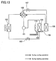
- Patent Literature 1 discloses an air conditioner for an electric vehicle as shown in Fig. 13 .
- This air conditioner includes a compressor 101 driven by an electric motor, an outside heat exchanger 102, an expansion valve 103, a heat absorbing indoor heat exchanger 104, and a four-way valve 105 for forming a loop connecting these components 101 to 104 in this order during a cooling operation.
- a heat releasing indoor heat exchanger 106 and an expansion valve 107 are connected to the other two ports of the four-way valve 105 so as to form another loop.
- Air inside the cabin is supplied to the heat absorbing indoor heat exchanger 104 by a fan 110.
- a high temperature and high pressure gas refrigerant compressed in the compressor 101 is introduced to the heat releasing indoor heat exchanger 106 during a heating operation, and this heat releasing indoor heat exchanger 106 is placed downstream of the heat absorbing indoor heat exchanger 104 in the direction of the air flow formed by the fan 110.
- the gas refrigerant compressed in the compressor 101 flows through the four-way valve 105 in a direction of a solid line arrow, changes to a liquid refrigerant through heat exchange with outside air in the outdoor heat exchanger 102, and then is throttled through the expansion valve 103 and adiabatically expanded.
- the adiabatically expanded liquid refrigerant changes to a gas refrigerant through heat exchanger with cabin circulating air supplied by the fan 110 in the heat absorbing indoor heat exchanger 104, and returns to the compressor 101.
- the gas refrigerant compressed in the compressor 101 flows through the four-way valve 105 in a direction of a dotted line arrow, changes to a liquid refrigerant through heat exchange with cabin circulating air supplied by the fan 110 in the heat releasing indoor heat exchanger 106, while heating the circulating air.
- the liquid refrigerant leaving the heat releasing indoor heat exchanger 106 passes through the expansion valve 107, the four-way valve 105, the outdoor heat exchanger 102, the expansion valve 103, and the heat absorbing indoor heat exchanger 104 in this order and returns to the compressor 101.
- the liquid refrigerant is throttled through the expansion valve 107 and adiabatically expanded, and then changes to a gas refrigerant through heat absorption in the outdoor heat exchanger 102 and in the heat absorbing indoor heat exchanger 104, while cooling the circulating air in the outdoor heat exchanger 102.
- condensation water is generated on the surface of the heat absorbing indoor heat exchanger 104.
- the condensation water drops into a drain pan 108 and is exhausted through a drain pipe 109 to the outside of the cabin.
- the air inside the cabin circulated by the fan 110 is cooled and dehumidified in the heat absorbing indoor heat exchanger 104, but it is heated in the heat releasing indoor heat exchanger 106. This makes it possible to perform heating while dehumidifying the air inside the cabin.
- the present invention has been made to solve the above conventional problems, and it is an object of the present invention to provide a vehicle air conditioner intended to simplify the control during a heating operation and a cooling operation.
- the present invention provides a vehicle air conditioner for cooling and heating a cabin.
- This vehicle air conditioner includes: a heat pump circuit including: a compressor for compressing a refrigerant; an outdoor heat exchanger for performing heat exchange between the refrigerant and air outside the cabin; an expansion mechanism for expanding the refrigerant; and a first indoor heat exchanger and a second indoor heat exchanger each for performing heat exchange between the refrigerant and air blown into the cabin by a fan; and a switching member, provided in the heat pump circuit, for switching a flow direction of the refrigerant in the heat pump circuit between a first direction and a second direction.
- the first direction is a direction in which the refrigerant discharged from the compressor passes through the outdoor heat exchanger, the expansion mechanism, the first indoor heat exchanger, and the second indoor heat exchanger in this order and returns to the compressor
- the second direction is a direction in which the refrigerant discharged from the compressor passes through the first indoor heat exchanger, the expansion mechanism, the outdoor heat exchanger, and the second indoor heat exchanger in this order and returns to the compressor, a duct in which the first indoor heat exchanger and the second indoor heat exchanger are disposed, and through which air inside the cabin and/or air outside the cabin is allowed to flow by the fan; wherein the first indoor heat exchanger and the second indoor heat ex-changer are arranged in a flow direction of the air in the duct, and the second indoor heat exchanger is located upstream of the first indoor heat exchanger.
- both of a cooling operation (in the first direction) and a heating operation (in the second direction) can be performed with a simple configuration to control a single expansion valve.
- Fig. 1 is a diagram showing the configuration of a vehicle air conditioner 10A according to the first embodiment of the present invention.
- This vehicle air conditioner 10A is designed to cool and heat a cabin (not shown), and includes a heat pump circuit 2 for circulating a refrigerant and a controller 5.
- a refrigerant R143a, R410A, HFO-1234yf, CO 2 , or the like can be used.
- the heat pump circuit 2 includes a compressor 11, an outdoor heat exchanger 13, an expansion valve 14, a first indoor heat exchanger 15, and a second indoor heat exchanger 16.
- the heat pump circuit 2 is further provided with a four-way valve 12A, as a switching member.
- the valve 12A switches the flow direction of the refrigerant in the heat pump circuit 2 between the first direction indicated by dotted line arrows and a second direction indicated by solid line arrows.
- the first direction is a direction in which the refrigerant discharged from the compressor 11 passes through the outdoor heat exchanger 13, the expansion valve 14, the first indoor heat exchanger 15, and the second indoor heat exchanger 16 in this order and returns to the compressor 11.
- the second direction is a direction in which the refrigerant discharged from the compressor 11 passes through the first indoor heat exchanger 15, the expansion valve 14, the outdoor heat exchanger 13, and the second indoor heat exchanger 16 in this order and returns to the compressor 11. That is, both of the cooling operation (in the first direction) and the heating operation (in the second direction) can be performed with a simple configuration to control a single expansion valve 14.
- the four-way valve 12A is configured to be shifted between a first position in which a first port 12a is in communication with a second port 12b and a third port 12c is in communication with a fourth port 12d and a second position in which the first port 12a is in communication with the third port 12c and the second port 12b is in communication with the fourth port 12d.
- the four-way valve 12A is shifted to the first position during the cooling operation and to the second position during the heating operation by the controller 5.
- the compressor 11 is designed to be driven by an electric motor (not shown), and compresses a refrigerant drawn through an inlet and discharges the compressed refrigerant through an outlet.
- the outlet of the compressor 11 is connected to the first port 12a of the four-way valve 12A by a first pipe 21.
- the outdoor heat exchanger 13 is placed, for example, in the front of an automobile, and exchanges heat between the refrigerant and outside air (air outside the cabin) supplied by the movement of the vehicle and by the outdoor fan 17.
- the outdoor heat exchanger 13 is connected to the second port 12b of the four-way valve 12A by a second pipe 22.
- the expansion valve 14 is designed to expand the refrigerant, and is one example of the expansion mechanism of the present invention.
- a positive displacement expander for recovering power from an expanding refrigerant, or the like may be used.
- the expansion valve 14 is connected to the outdoor heat exchanger 13 by a third pipe 23.
- the first indoor heat exchanger 15 and the second indoor heat exchanger 16 each exchange heat between the refrigerant and air blown into the cabin by the indoor fan 4.
- the first indoor heat exchanger 15 is connected to the expansion valve 14 by a fourth pipe 24 and to the third port 12c of the four-way valve 12A by a fifth pipe 25.
- the second indoor heat exchanger 16 is connected to the fourth port 12d of the four-way valve 12A by a sixth pipe 26 and to the inlet of the compressor 11 by a seventh pipe 27.
- the seventh pipe 27 is provided with an accumulator 18.
- the first indoor heat exchanger 15 and the second indoor heat exchanger 16 are disposed in a duct 31 through which air inside the cabin is allowed to flow by the indoor fan 4. That is, the air inside the cabin is circulated through the duct 31.
- the duct 31 is provided with a drain pipe 32 for exhausting water that has been separated from the cabin circulating air in the duct 31 to the outside of the cabin.
- All of the air that is allowed to flow through the duct 31 by the indoor fan 4 need not be the air inside the cabin.
- a part or all of the air may be outside air used to ventilate the cabin. The following description is given by taking, as an example, the case where all of the air taken into the duct 31 by the indoor fan 4 and supplied to the first indoor heat exchanger 15 and the second indoor heat exchanger 16 is the air inside the cabin.
- the first indoor heat exchanger 15 and the second indoor heat exchanger 16 are arranged in the flow direction of the air in the duct 31, and the second indoor heat exchanger 16 is located upstream of the first indoor heat exchanger 15.
- Both of the second indoor heat exchanger 16 and the first indoor heat exchanger 15 have a size large enough to fill the space inside the duct 31. Therefore, when the air inside the cabin is taken into the duct 31 by the indoor fan 4, the air comes in contact with the second indoor heat exchanger 16 and then with the first indoor heat exchanger 15.
- the indoor fan 4 may be disposed at the outlet of the duct 31 as shown in Fig. 1 , or may be disposed at the inlet of the duct 31 as shown in Fig. 3 .
- a blower may be used as the indoor fan 4.
- the above-mentioned seventh pipe 27 connecting the second indoor heat exchanger 16 and the inlet of the compressor 11 is provided with a superheat sensor 62 (corresponding to a refrigerant temperature sensor of the present invention) for detecting the temperature of the refrigerant leaving the second indoor heat exchanger 16, and further with a pressure sensor 61 for detecting the pressure of the refrigerant drawn into the compressor 11.
- the superheat sensor 62 is placed inside the duct 31, but it may be placed outside the duct 31.
- the pressure sensor 61 may be provided in the sixth pipe 26.
- the controller 5 is connected to an operation panel (not shown) disposed in the cabin and to the superheat sensor 62 and the pressure sensor 61.
- the controller 5 controls the driving of the outdoor fan 17 and the indoor fan 4, the rotational speed of the compressor 11, and the opening of the expansion valve 14, and shifts the four-way valve 12A.
- the four-way valve 12A is shifted to the second position by the controller 5, and a high temperature and high pressure gas refrigerant compressed in the compressor 11 flows through the four-way valve 12A in the direction of a solid line arrow.
- the gas refrigerant releases heat to the cabin circulating air supplied by the indoor fan 4 and condenses in the first indoor heat exchanger 15, while heating the cabin circulating air.
- the resulting liquid refrigerant is throttled through the expansion valve 14 and adiabatically expanded into a low temperature and low pressure state. Then, the refrigerant absorbs heat from the outside air and a part thereof evaporates in the outdoor heat exchanger 13.
- the refrigerant leaving the outdoor heat exchanger 13 again passes through the four-way valve 12A and enters the second indoor heat exchanger 16.
- the refrigerant absorbs heat from the cabin circulating air supplied by the indoor fan 4 and the remaining part of the liquid refrigerant evaporates, while cooling the cabin circulating air.
- condensation water is generated on the surface of the second indoor heat exchanger 16, and the cabin circulating air is dehumidified.
- the condensation water drops into a drain pan (not shown) disposed in the duct 31 and is exhausted through a drain pipe 32 to the outside of the cabin.
- the gas refrigerant leaving the second indoor heat exchanger 16 is again drawn into the compressor 11.
- the cabin circulating air which is taken into the duct 31 by the indoor fan 4, is dehumidified while passing through the second indoor heat exchanger 16, and then heated while passing through the first indoor heat exchanger 15. This makes it possible to perform heating while dehumidifying the cabin circulating air.
- Fig. 2 shows a Mollier diagram of the vehicle air conditioner 10A of the present embodiment during the heating operation. Each process of the cycle of Fig. 2 is described below.
- a refrigerant in a low temperature and low pressure state is compressed in the compressor 11 to a high temperature and high pressure state (state B).
- the high temperature and high pressure refrigerant changes to a medium temperature and high pressure state (state C).
- the medium temperature and high pressure refrigerant changes to a low temperature and low pressure gas-liquid two phase refrigerant (state D).
- the outdoor heat exchanger 13 While passing through the outdoor heat exchanger 13, the gas-liquid two phase refrigerant absorbs heat and evaporates (state E).
- the refrigerant that has passed through the outdoor heat exchanger 13 takes a quantity of heat corresponding to the latent heat from the air inside the cabin and changes to the state A. That is, the quantity of heat released in the first indoor heat exchanger 15 (i.e., a change from the state B to the state C) can be increased by the quantity of heat corresponding to the latent heat (i.e., a change from the state E to the state A). Therefore, the latent heat of the moisture in the air recovered in the second indoor heat exchanger 16 can be used for heating.
- the four-way valve 12A is shifted to the first position by the controller 5, and a high temperature and high pressure gas refrigerant compressed in the compressor 11 flows through the four-way valve 12A in the direction of a dotted line arrow.
- the gas refrigerant releases heat to the outside air and condenses in the outdoor heat exchanger 13.
- the resulting liquid refrigerant is throttled through the expansion valve 14 and adiabatically expanded into a low temperature and low pressure state. Then, the refrigerant absorbs heat from the cabin circulating air supplied by the indoor fan 4 and a part thereof evaporates in the first indoor heat exchanger 15, while cooling the cabin circulating air.
- the refrigerant leaving the first indoor heat exchanger 15 again passes through the four-way valve 12A and enters the second indoor heat exchanger 16.
- the refrigerant absorbs heat from the cabin circulating air supplied by the indoor fan 4 and the remaining part of the liquid refrigerant evaporates, while cooling the cabin circulating air.
- the refrigerant passes through the first indoor heat exchanger 15, its pressure is reduced by an amount corresponding to the pressure loss therein, and thus the evaporation temperature in the second indoor heat exchanger 16 becomes lower than that in the first indoor heat exchanger 15. Therefore, the cabin circulating air is dehumidified mainly in the second indoor heat exchanger 16.
- the gas refrigerant leaving the second indoor heat exchanger 16 is again drawn into the compressor 11.
- the cabin circulating air which is taken into the duct 31 by the indoor fan 4, is cooled while passing through the second indoor heat exchanger 16 and the first indoor heat exchanger 15.
- the cooling capacity and the efficiency of the refrigeration cycle can be improved.
- the dryness of the refrigerant leaving the second indoor heat exchanger 16 varies with a change in the running speed of the vehicle or a change in the temperature set for the cabin by a user.
- the degree of superheat which is the temperature difference between the temperature of the refrigerant leaving the second indoor heat exchanger 16 and the saturation temperature of the refrigerant at a pressure at which it is drawn into the compressor 11
- a predetermined value for example, 3°C to 5°C
- the degree of superheat is greater than a predetermined value (for example, 5°C to 7°C)
- a predetermined value for example, 5°C to 7°C
- the COP Coefficient of Performance
- the refrigerant circulation amount is the key to the control of the capacity of a heat pump.
- the refrigerant circulation amount depends on the rotational speed of the compressor 11. If the rotational speed of the compressor 11 is excessively high, there is an increased risk that the discharge pressure and the discharge temperature increase beyond the pressure and the temperature low enough to ensure the reliability. That is, if the pressure of the refrigerant discharged from the compressor 11 rises too high, the closed casing and the mechanism constituting the compressor 11 are subjected to load, which may cause damage to these devices. Furthermore, if the temperature of the refrigerant discharged from the compressor 11 rises too high, that temperature may exceed the highest temperature that the insulating coating of the winding of the driving motor of the compressor 11 can withstand.
- the controller 5 controls the rotational speed of the compressor 11 and the opening of the expansion valve 14 in accordance with the degree of superheat and the required capacity depending on the inputs into the operation panel, to maintain the optimum cycle conditions for the heat pump.
- the controller 5 controls, in accordance with the required capacity, the rotational speed of the compressor 11 to such an extent that the discharge temperature from the compressor 11 does not exceed a predetermined temperature (for example, 100°C).
- a predetermined temperature for example, 100°C.
- the upper limit of the rotational speed of the compressor 11 may be predetermined, or a discharge temperature sensor may be provided in the first pipe 21 to monitor the temperature of the refrigerant discharged from the compressor 11.
- the controller 5 has a memory (not shown), and the saturation temperatures corresponding to the pressures of the refrigerant are stored in this memory.
- the controller 5 reads out from the memory a saturation temperature at a pressure detected by the pressure sensor 61, as appropriate, compares the read-out saturation temperature with the refrigerant temperature detected by the superheat sensor 62, and controls the opening of the expansion valve 14 so that the temperature difference between these temperatures coincides with a predetermined degree of superheat.
- the controller 5 allows the temperature of the discharged refrigerant to be maintained at a temperature equal to or lower than a predetermined temperature based on the proper rotational speed of the compressor 11, while maintaining the degree of superheat of the refrigerant drawn into the compressor 11 constant based on the proper opening of the expansion valve 14. As a result, the optimum cycle conditions for the heat pump can be maintained.
- the opening of the expansion valve 14 can be arbitrarily determined from the fully closed position to the fully open position, with the movement of the valve in accordance with the rotation of a stepping motor. If 480 steps are required to change the opening of the expansion valve 14 from the fully closed position to the fully open position, 0 to 480 pulse signals are input to the stepping motor.
- the expansion valve 14 is opened at an initial opening PLS0, which is set in accordance with the required capacity. For example, if the required capacity has three levels, the initial opening PLS0 is set to, for example, 16.7% (80 steps), 20.8% (100 steps), and 25% (120 steps), in accordance with these levels of the required capacity. For five minutes after the start of the operation, the initial opening is maintained, and then the opening is changed by the degree corresponding to the microsteps ⁇ PLS to be moved every 30 seconds, for example.
- the cooling operation and the heating operation can be switched instantaneously only by shifting the four-way valve 12A.
- the cabin circulating air is dehumidified in the second indoor heat exchanger 16 during the heating operation.
- it is dehumidified mainly in the second indoor heat exchanger 16 because the evaporation temperature in the second indoor heat exchanger 16 is lower than that in the first indoor heat exchanger 15, as described above.
- the second indoor heat exchanger 16 always contributes to the dehumidification. Therefore, it is possible to prevent condensation water on the surface of the second indoor heat exchanger 16 from evaporating and thus causing degradation of the in-vehicle environment or fogging of the windshield even when the cooling operation is switched to the heating operation.
- the refrigerant is confined in a flow path including the indoor heat exchanger 106, as a closed space, during the cooling operation.
- the refrigerating machine oil also is trapped therein and the amount of oil required for the compressor cannot be secured, which adversely affects the operation. Therefore, when the outside air temperature rises, the pressure of the confined refrigerant in the flow path increases, which may cause damage to the devices constituting the flow path.
- the present embodiment even if the cooling operation and the heating operation are switched, no such flow path is formed to confine the refrigerant. Therefore, it is possible to prevent the adverse effects of the pressure increase of the refrigerant with an increase in outside air temperature.
- the opening of the two expansion valves 103, 107 must be controlled in addition to the control of the four-way valve 105 to switch the heating operation and the cooling operation. Therefore, complicated control is required, resulting in deterioration in the size, reliability and cost of the air conditioner including the piping system and the expansion valves.
- the cooling operation and the heating operation can be performed with a simple configuration to control a four-way valve and a single expansion mechanism.
- the saturation temperatures corresponding to the pressures of the refrigerant are stored in the memory of the controller 5, and the controller 5 reads out from the memory a saturation temperature at a pressure detected by the pressure sensor 61, but the present invention is not limited to this.
- the fact that the refrigerant is in the gas-liquid two phase state between the expansion valve 14 and the evaporator i.e., the outdoor heat exchanger 13 during the heating operation, and the first indoor heat exchanger 15 during the cooling operation
- the refrigerant is in the gas-liquid two phase state between the expansion valve 14 and the evaporator (i.e., the outdoor heat exchanger 13 during the heating operation, and the first indoor heat exchanger 15 during the cooling operation) may be used to obtain a saturation temperature.
- a first gas-liquid refrigerant temperature sensor 63 is provided in the third pipe 23 connecting the expansion valve 14 and the outdoor heat exchanger 13 and a second gas-liquid refrigerant temperature sensor 64 is provided in the fourth pipe 24 connecting the expansion valve 14 and the first indoor heat exchanger 15.
- the controller 5 can use, as a saturation temperature, a value detected by the first gas-liquid refrigerant temperature sensor 63 during the heating operation, and a value detected by the second gas-liquid refrigerant temperature sensor 64 during the cooling operation.
- a saturation temperature sensor 65 for detecting the temperature of the refrigerant entering the second indoor heat exchanger 16 may be provided in the sixth pipe 26 to use a value detected by the saturation temperature sensor 65 as a saturation temperature.
- the temperature of the evaporator i.e., the outdoor heat exchanger 13 during the heating operation, and the first indoor heat exchanger 15 during the cooling operation
- the temperature of the evaporator also can be used instead of the saturation temperature.
- the first indoor heat exchanger 15 and the second indoor heat exchanger 16 need not necessarily be arranged in the air flow direction in the duct 31.
- they may be arranged in the direction perpendicular to the air flow direction in the duct 31.
- the sixth pipe 26 and the seventh pipe 27 may be connected by a bypass passage 19 provided with an on-off valve 19a to bypass the second indoor heat exchanger 16 so that the on-off valve 19a is opened when no dehumidification is necessary during the heating operation.
- This not only prevents the air from being cooled in the duct 31, but also prevents the pressure of the refrigerant drawn into the compressor 11 from dropping due to the pressure loss in the second indoor heat exchanger 16.
- the bypass passage 19 may connect the second pipe 22 and the seventh pipe 27.
- Fig. 8 is a diagram showing the configuration of a vehicle air conditioner 10B according to the second embodiment of the present invention.
- the same components as those in the first embodiment are designated by the same reference numerals, and no further description is given.
- the four-way valve 12A is shifted to the second position so that the flow direction of the refrigerant flowing in the heat pump circuit 2 is switched to the second direction indicated by solid line arrows
- the four-way valve 12A is shifted to the first position so that the flow direction of the refrigerant flowing in the heat pump circuit 2 is switched to the first direction indicated by dotted line arrows. Therefore, the operation of each device and the flowing manner of the refrigerant are the same as those in the vehicle air conditioner 10A of the first embodiment shown in Fig. 1 .
- the refrigerant R143a, R410A, HFO-1234yf, CO 2 , or the like can be used, as in the first embodiment.
- the second indoor heat exchanger 16 located upstream of the first indoor heat exchanger 15 in the air flow direction in the duct 31 is disposed so that a first flow path 7A passing through the second indoor heat exchanger 16 and a second flow path 7B not passing through the second indoor heat exchanger 16 are layered in the duct 31.
- the second indoor heat exchanger 16 may be disposed on one side of the duct 31 near the wall thereof so that the first indoor heat exchanger 15 is exposed to the upstream side from beside the second indoor heat exchanger 16, in other words, so that some space in which air bypassing the second indoor heat exchanger 16 can flow is formed beside the second indoor heat exchanger 16.
- a portion of the duct 31 surrounding the second indoor heat exchanger 16 may be expanded so that air bypassing the second indoor heat exchanger 16 can flow through the expanded portion.
- the duct 31 has an inner wall consisting of a ceiling, a bottom, and a pair of laterals, the second indoor heat exchanger 16 preferably is placed adjacent to the bottom of the duct 31 away from the ceiling thereof.
- a damper 71 is provided upstream of the second indoor heat exchanger 16 in the duct 31.
- This damper 71 adjusts the ratio between the amount of air flowing through the first flow path 7A leading to the first indoor heat exchanger 15 through the second indoor heat exchanger 16 and the amount of air flowing through the second flow path 7B leading to the first indoor heat exchanger 15 not through the second indoor heat exchanger 16.
- a partition 72 that is flat in the air flow direction in the duct 31 and separates the first flow path 7A and the second flow path 7B is provided in the duct 31.
- the pivot shaft of the damper 71 is mounted at the end of the partition 72 opposite to the first indoor heat exchanger 15.
- the air taken into the duct 31 by the indoor fan 4 is divided by the damper 71 into a stream flowing through the first flow path 7A and a stream flowing through the second flow path 7B.
- the stream of air flowing through the first flow path 7A comes in contact with the second indoor heat exchanger 16 and is cooled and dehumidified. Then, it comes in contact with the first indoor heat exchanger 15 and is heated or cooled.
- the stream of air flowing through the second flow path 7B comes in contact only with the first indoor heat exchanger 15 and is heated or cooled.
- the damper is swung by a servo motor (not shown). It is preferable to control the velocity of the air passing through the second indoor heat exchanger 16 in order to maximize the dehumidification performance of the second indoor heat exchanger 16. Therefore, the proportion of air to be distributed (hereinafter referred to simply as a "proportion of distribution") to the first flow path 7A by the damper 71 is determined according to the air volume of the indoor fan 4. For example, if the operation of the indoor fan 4 has three levels, high, medium and low, the proportion of distribution also is set to three levels, high, medium and low to control the damper angle according to the operation level of the indoor fan 4. For example, high, medium, and low proportions of distribution are 100%, 50%, and 25%, respectively.
- the second flow path 7B is closed when the damper 71 is in the high distribution proportion state, equal amounts of air are allowed to flow through the first flow path 7A and the second flow path 7B when the damper 71 is in the medium distribution proportion state, and the first flow path 7A is semi-closed when the damper 71 is in the low distribution proportion state.
- the damper 71 can adjust, with its angle, the ratio of the amount of air to be brought into contact with the second indoor heat exchanger 16 and the amount of air not to be brought into contact with the second indoor heat exchanger 16. Then, these streams of air are merged downstream of the first indoor heat exchanger 15, and the merged air is blown into the cabin.
- the damper 71 is shifted to the low distribution proportion state when the operation level of the indoor fan 4 is high, to the medium distribution proportion state when the operation level is medium, and to the high distribution proportion state when the operation level is low. Under this control, the velocity of the air passing through the second indoor heat exchanger 16 can be maintained constant.
- a placement of a dehumidification temperature sensor 66 at the outlet of the first flow path 7A to detect the temperature of the air that has passed through the second indoor heat exchanger 16 allows the surface of the second indoor heat exchanger 16 to be controlled to prevent its drying. According to this control, the latent heat of the moisture in the air can be reliably recovered in the second heat exchanger 16 during the heating operation.
- the temperature difference between the temperature of the surface of the second indoor heat exchanger 16 and the temperature of the air detected by the dehumidification temperature sensor 66 may be maintained at a predetermined value (for example, 1°C to 5°C), assuming that the former temperature is equal to the saturation temperature of the refrigerant at a pressure at which it is drawn into the compressor 11.
- Tdh the temperature of the air detected by the dehumidification temperature sensor 66 and Tscsat is the saturation temperature of the refrigerant at a pressure at which it is drawn into the compressor 11 (i.e., the temperature of the refrigerant detected by the first liquid-gas refrigerant temperature sensor 63 or the second liquid-gal refrigerant temperature sensor 64 in the present embodiment)
- Tscsat 5°C
- Tdh 10°C
- ⁇ D -2%
- the cooling operation and the heating operation can be switched instantaneously only by shifting the four-way valve 12A. Furthermore, the dehumidification capacity can be adjusted during each of the cooling operation and the heating operation by using the damper 71 to control the amount of air to be brought into contact with the second indoor heat exchanger 16 and the amount of air not to be brought into contact with the second indoor heat exchanger 16.
- the cooling operation and the heating operation can be performed with a simple configuration to control a four-way valve and a single expansion mechanism.
- the damper 71 is provided on the windward side of the partition 72, but the damper 71 may be provided on the leeward side of the partition 72.
- the partition 72 is provided in the duct 31, but even without the partition 72, the damper 71 can be used to change the ratio between the amount of air flowing through the first flow path 7A and the amount of air flowing through the second flow path 7B. Furthermore, there is no space between the partition 72 and the first indoor heat exchanger 15 in Fig. 8 , but there may be a space for allowing the streams of air to mix therein.
- Fig. 9 is a diagram showing the configuration of a vehicle air conditioner 10C according to the third embodiment of the present invention.
- the same components as those in the first embodiment are designated by the same reference numerals, and no further description is given.
- the four-way valve 12A is shifted to the second position so that the flow direction of the refrigerant in the heat pump circuit 2 is switched to the second direction indicated by solid line arrows
- the four-way valve 12A is shifted to the first position so that the flow direction of the refrigerant in the heat pump circuit 2 is switched to the first direction indicated by dotted line arrows. Therefore, the operation of each device and the flowing manner of the refrigerant are the same as those in the vehicle air conditioner 10A of the first embodiment shown in Fig. 1 .
- the refrigerant R143a, R410A, HFO-1234yf, CO 2 , or the like can be used, as in the first embodiment.
- the first indoor heat exchanger 15 located downstream of the second indoor heat exchanger 16 in the air flow direction in the duct 31 is disposed so that a third flow path 7C passing through the first indoor heat exchanger 15 and a fourth flow path 7D not passing through the first indoor heat exchanger 15 are layered in the duct 31.
- the first indoor heat exchanger 15 may be placed on one side of the duct 31 near the wall thereof so that the second indoor heat exchanger 16 is exposed to the downstream side from beside the first indoor heat exchanger 15, when viewed from the downstream side, in other words, so that some space in which air bypassing the first indoor heat exchanger 15 can flow is formed beside the first indoor heat exchanger 15.
- a portion of the duct 31 surrounding the first indoor heat exchanger 15 may be expanded so that the air bypassing the first indoor heat exchanger 15 can flow through the expanded portion.
- the duct 31 has an inner wall consisting of a ceiling, a bottom and a pair of laterals, the first indoor heat exchanger 15 preferably is placed adjacent to the bottom of the duct 31 away from the ceiling thereof.
- a damper 71 is provided upstream of the first indoor heat exchanger 15 in the duct 31.
- This damper 71 adjusts the ratio between the amount of air flowing through a third flow path 7C leading to the outlet of the duct through the first indoor heat exchanger 15 and the amount of air flowing through a fourth flow path 7D leading to the outlet of the duct not through the first indoor heat exchanger 15.
- a partition 72 that is flat in the air flow direction in the duct 31 and separates the third flow path 7C and the fourth flow path 7D is provided in the duct 31.
- the pivot shaft of the damper 71 is mounted at the end of the partition 72 near the second indoor heat exchanger 16.
- the air taken into the duct 31 by the indoor fan 4 is divided by the damper 71 into a stream flowing through the third flow path 7C and a stream flowing through the fourth flow path 7D.
- the stream of air flowing through the third flow path 7C comes in contact with the second indoor heat exchanger 16 and is cooled and dehumidified. Then, it comes in contact with the first indoor heat exchanger 15 and is heated or cooled.
- the stream of air flowing through the fourth flow path 7D comes in contact only with the second indoor heat exchanger 16 and is cooled and dehumidified.
- the damper 71 is swung by a servo motor (not shown).
- the damper 71 can adjust, with its angle, the ratio of the amount of air to be brought into contact with the first indoor heat exchanger 15 and the amount of air not to be brought into contact with the first indoor heat exchanger 15. Then, these streams of air are merged downstream of the first indoor heat exchanger 15, and the merged air is blown into the cabin.
- An exiting air temperature sensor 67 in Fig. 9 is a sensor for detecting the temperature of the air blown into the cabin from the duct 31.
- the proportion of distribution to the third flow path 7C by the damper 71 is controlled using the servo motor so that the temperature detected by the exiting air temperature sensor 67 becomes equal to Tw (i.e., the temperature of the exiting air required to maintain the cabin temperature at a preset temperature).
- the cooling operation and the heating operation can be switched instantaneously only by shifting the four-way valve 12A. Furthermore, the temperature of the air at the outlet of the duct 31 can be adjusted by using the damper 71 to control the amount of air to be brought into contact with the first indoor heat exchanger 15 and the amount of air not to be brought into contact with the first indoor heat exchanger 15.
- the cooling operation and the heating operation can be performed with a simple configuration to control a four-way valve and a single expansion mechanism.
- Fig. 10 is a diagram showing the configuration of a vehicle air conditioner 10D according to the fourth embodiment of the present invention.
- This vehicle air conditioner 10D has a configuration that combines the vehicle air conditioner 10B of the second embodiment and the vehicle air conditioner 10C of the third embodiment.
- the second indoor heat exchanger 16 is disposed so that a first flow path 7A passing through the second indoor heat exchanger 16 and a second flow path 7B not passing through the second indoor heat exchanger 16 are layered in the duct 31, and the first indoor heat exchanger 15 is disposed so that a third flow path 7C passing through the first indoor heat exchanger 15 and a fourth flow path 7D not passing through the first indoor heat exchanger 15 are layered in the duct 31.
- the specific configurations of these components are the same as those described in the second embodiment and the third embodiment.
- the duct 31 further has a first damper 71A therein for adjusting the ratio between the amount of air flowing through the first flow path 7A and the amount of air flowing through the second flow path 7B, and has a second damper 71B therein for adjusting the ratio between the amount of air flowing through the third flow path 7C and the amount of air flowing through the fourth flow path 7D.
- the pivot shaft of the first damper 71A is mounted at the windward end of a partition 72 for separating the first flow path 7A and the second flow path 7B
- the pivot shaft of the second damper 71B is mounted at the windward end of a partition 72 for separating the third flow path 7C and the fourth flow path 7D.
- the air taken into the duct 31 by the indoor fan 4 is divided by the first damper 71A into a stream flowing through the first flow path 7A and a stream flowing through the second flow path 7B.
- the stream of air flowing through the first flow path 7A comes in contact with the second indoor heat exchanger 16 and is cooled and dehumidified. Then, it is merged with the stream of air flowing through the second flow path 7B.
- the merged air is divided by the second damper 71B into a stream flowing through the third flow path 7C and a stream flowing through the fourth flow path 7D.
- the stream of air flowing through the third flow path 7C comes in contact with the first indoor heat exchanger 15 and is heated or cooled. Then, it is merged with the stream of air flowing through the fourth flow path 7D.
- the merged air is blown from the duct 31 into the cabin.
- the first damper 71A and the second damper 71B are swung by a servo motor (not shown).
- the first damper 71A can adjust, with its angle, the ratio of the amount of air to be brought into contact with the second indoor heat exchanger 16 and the amount of air not to be brought into contact with the second indoor heat exchanger 16.
- the second damper 71B can adjust, with its angle, the ratio of the amount of air to be brought into contact with the first indoor heat exchanger 15 and the amount of air not to be brought into contact with the first indoor heat exchanger 15.
- the four-way valve 12A is shifted to the second position, so that the flow direction of the refrigerant in the heat pump circuit 2 is switched to the second direction indicated by solid line arrows.
- the proportion of distribution to the first flow path 7A by the first damper 71A is minimized (0%), and the proportion of distribution to the third flow path 7C by the second damper 71B is maximized (100%). That is, the air taken into the duct 31 by the indoor fan 4 is brought into contact only with the first indoor heat exchanger 15.
- the proportion of distribution to the third flow path 7C by the second damper 71B is maximized (100%), while the proportion of distribution to the first flow path 7A by the first damper 71A is set to an intermediate value at which an appropriate amount of air is supplied to the second heat exchanger 16.
- both of the proportion of distribution to the first flow path 7A by the first damper 71A and the proportion of distribution to the third flow path 7C by the second damper 71B may be set to an intermediate value.
- the four-way valve 12A is shifted to the first position so that the flow direction of the refrigerant in the heat pump circuit 2 is switched to the first direction indicated by dotted line arrows.
- both of the proportion of distribution to the first flow path 7A by the first damper 71A and the proportion of distribution to the third flow path 7C by the second damper 71B are maximized (100%). That is, the air taken into the duct 31 by the indoor fan 4 is brought into contact with both of the second indoor heat exchanger 16 and the first indoor heat exchanger 15.
- the dehumidification capacity may be enhanced.
- the proportion of distribution to the first flow path 7A by the first damper 71A is set to an intermediate value at which an appropriate amount of air is supplied to the second heat exchanger 16
- the proportion of distribution to the third flow path 7C by the second damper 71B is set to an intermediate value at which an appropriate amount of air is supplied to the first heat exchanger 15.
- either one of the proportion of distribution to the first flow path 7A by the first damper 71A and the proportion of distribution to the third flow path 7C by the second damper 71B may be minimized (0%).
- the angles of the first damper 71A and the second damper 71B may be fixed for the operation mode as described above so that the air conditioning capacity is adjusted by the rotational speed of the compressor 11.
- the angles of the first damper 71A and the second damper 71B also may be changed.
- the angle of the first damper 71A may be adjusted according to the operation level of the indoor fan 4 so that the air passes through the second indoor heat exchanger 16 at a constant velocity, in the same manner as described in the second embodiment.
- the angle of the first damper 71A may be adjusted based on the temperature of the air detected by the dehumidification temperature sensor 66 and on the saturation temperature of the refrigerant at a pressure at which it is drawn into the compressor 11 so that the surface of the second indoor heat exchanger 16 does not dry out, in the same manner as described in the second embodiment.
- the angle of the second damper 71B may be adjusted based on the temperature of the air detected by the exiting air temperature sensor 67, in the same manner as described in the second embodiment.
- the cooling operation and the heating operation can be performed with a simple configuration to control a four-way valve and a single expansion mechanism.
- the second indoor heat exchanger 16 and the first indoor heat exchanger 15 are arranged on the same side of the partitions 72, and the first flow path 7A passing through the second indoor heat exchanger 16 and the third flow path 7C passing through the first indoor heat exchanger 15 form a continuous flow path.
- the arrangement of the second indoor heat exchanger 16 and the first indoor heat exchanger 15 is not limited to this.
- the second indoor heat exchanger 16 and the first indoor heat exchanger 15 may be arranged on the opposite sides of the partitions 72 so that the first flow path 7Apassing through the second indoor heat exchanger 16 and the fourth flow path 7D not passing through the first indoor heat exchanger 15 form a continuous flow path and that the first flow path 7B not passing through the second indoor heat exchanger 16 and the third flow path 7C passing through the first indoor heat exchanger 15 form a continuous flow path.
- the air taken into the duct 31 by the indoor fan 4 is brought into contact with both of the second indoor heat exchanger 16 and the first indoor heat exchanger 15 in parallel. Therefore, the pressure drop of the air passing through the duct 31 and the cooling efficiency can be improved.
- the heating operation or the cooling operation can be performed under appropriate conditions for the required capacity by performing the same control as in the embodiment described above.
- the switching member 12A is used as a switching member, but the switching member of the present invention is not limited to this.
- the switching member may be a circuit 12B in which two three-way valves 121, one connected to the first pipe 21 and the other connected to the sixth pipe 26, are connected to form a loop by a pair of pipes 122, one connected to the second pipe 22 and the other connected to the fifth pipe 25.
- the switching member may be a so-called bridge circuit 12C as shown in Fig. 12B .
- the indoor fan 4 is placed on the leeward side of the duct 31.
- the fan generates no swirl in the air flow on the suction side of the fan. Therefore, less turbulent air can be supplied to the second indoor heat exchanger 16 and the first indoor heat exchanger 15. As a result, the pressure loss is reduced, which reduces the rotational speed of the fan and the power consumption.
- the indoor fan 4 may be placed on the windward side of the duct 31.
- the noise of the fan can be reduced.
- the configuration in which the indoor fan 4 is placed on the windward side of the duct 31 even if condensation occurs on the surface of the indoor fan 4 by a change in the conditions of the air passing through the indoor fan 4, condensation water droplets are prevented from being blown off from the outlet of the duct 31.
- the vehicle air conditioner of the present invention has enhanced dehumidification capacity during the cooling operation to improve comfort and defogs the window glass during the heating operation to ensure clear visibility, it is useful particularly for non-combustion type vehicles such as electric vehicles and fuel cell vehicles.
Landscapes
- Physics & Mathematics (AREA)
- Thermal Sciences (AREA)
- Engineering & Computer Science (AREA)
- Mechanical Engineering (AREA)
- Air-Conditioning For Vehicles (AREA)
Claims (9)
- Fahrzeugklimaanlage (10 A, 10 B, 10 C, 10 D) zum Kühlen und Heizen eines Fahrzeuginnenraums, Folgendes umfassend:einen Wärmepumpenkreislauf (2), der Folgendes einschließt: einen Kompressor (11) zum Komprimieren eines Kältemittels; einen Außenwärmetauscher (13) zum Wärmeaustausch zwischen dem Kältemittel und der Luft außerhalb des Innenraums; einen Expansionsmechanismus (14) zum Expandieren des Kältemittels;und einen ersten Innenwärmetauscher (15) und einen zweiten Innenwärmetauscher (16), jeweils für einen Wärmeaustausch zwischen dem Kältemittel und der Luft, die durch ein Gebläse (4) in den Innenraum geblasen wird; undein Schaltelement (12 A), das in dem Wärmepumpenkreislauf (2) vorgesehen ist, zum Umschalten einer Strömungsrichtung des Kältemittels in dem Wärmepumpenkreislauf (2) zwischen einer ersten Richtung und einer zweiten Richtung,wobei die erste Richtung eine Richtung ist, in der das Kältemittel, das von dem Kompressor (11) abgeführt wird, durch den Außenwärmetauscher (13), den Expansionsmechanismus (14), den ersten Innenwärmetauscher (15) und den zweiten Innenwärmetauscher (16) - in dieser Reihenfolge - hindurchströmt, und zu dem Kompressor (11) zurückgeführt wird, undwobei die zweite Richtung eine Richtung ist, in der das Kältemittel, das von dem Kompressor (11) abgeführt wird, durch den ersten Innenwärmetauscher (15), den Expansionsmechanismus, den Außenwärmetauscher (13) und den zweiten Innenwärmetauscher (16) - in dieser Reihenfolge - hindurchströmt, und zu dem Kompressor (11) zurückgeführt wird;dadurch gekennzeichnet, dass diese Folgendes umfasst:einen Kanal (31), in welchem der erste Innenwärmetauscher (15) und der zweite Innenwärmetauscher (16) angeordnet sind, und durch welchen Luft im Inneren des Innenraums und / oder Luft außerhalb des Innenraums durch das Gebläse (4) ermöglicht wird, zu strömen; worinder erste Innenwärmetauscher (15) und der zweite Innenwärmetauscher (16) in einer Strömungsrichtung der Luft in dem Kanal (31) angeordnet sind, undder zweite Innenwärmetauscher (16) dem ersten Innenwärmetauscher (15) vorgeschaltet ist.
- Fahrzeugklimaanlage nach Anspruch 1, wobei der zweite Innenwärmetauscher (16) so angeordnet ist, dass ein erster Strömungspfad (7 A), der durch den zweiten Innenwärmetauscher (16) hindurchführt, und ein zweiter Strömungspfad (7 B), der nicht durch den zweiten Innenwärmetauscher (16) führt, in dem Kanal (31) geschichtet angeordnet sind.
- Fahrzeugklimaanlage (10 A, 10 B, 10 C, 10 D) nach Anspruch 2, wobei der Kanal (31) eine Luftklappe (71) darin aufweist, zum Einstellen eines Verhältnisses zwischen einer Menge an Luft, die durch den ersten Strömungspfad (7 A) strömt, und einer Menge an Luft, die durch den zweiten Strömungspfad (7 B) strömt.
- Fahrzeugklimaanlage (10 A, 10 B, 10 C, 10 D) nach Anspruch 3, wobei der Kanal (31) eine Trennwand (72) darin aufweist, zur Abtrennung des ersten Strömungspfades (7 A) von dem zweiten Strömungspfad (7 B).
- Fahrzeugklimaanlage (10 A, 10 B, 10 C, 10 D) nach Anspruch 1, wobei der erste Innenwärmetauscher (15) so angeordnet ist, dass ein dritter Strömungspfad (7 C), der durch den ersten Innenwärmetauscher (15) hindurchführt, und ein vierter Strömungspfad (7 D), der nicht durch den ersten Innenwärmetauscher (15) hindurchführt, in dem Kanal (31) geschichtet angeordnet sind.
- Fahrzeugklimaanlage (10 A, 10 B, 10 C, 10 D) nach Anspruch 1, wobei der zweite Innenwärmetauscher (16) so angeordnet ist, dass ein erster Strömungspfad (7 A), der durch den zweiten Innenwärmetauscher (16) hindurchführt, und ein zweiter Strömungspfad (7 B), der nicht durch den zweiten Innenwärmetauscher (16) hindurchführt, in dem Kanal (31) geschichtet angeordnet sind,
der erste Innenwärmetauscher (15) so angeordnet ist, dass ein dritter Strömungspfad (7 C), der durch den ersten Innenwärmetauscher (15) hindurchführt, und ein vierter Strömungspfad (7 D), der nicht durch den ersten Innenwärmetauscher (15) hindurchführt, in dem Kanal (31) geschichtet angeordnet sind, und
der Kanal (31) eine erste Luftklappe (71 A) darin aufweist, zum Einstellen eines Verhältnisses zwischen einer Menge an Luft, die durch den ersten Strömungspfad (7 A) strömt, und einer Menge an Luft, die durch den zweiten Strömungspfad (7 B) strömt, und eine zweite Luftklappe (71 B) darin aufweist, zum Einstellen eines Verhältnisses zwischen einer Menge an Luft, die durch den dritten Strömungspfad (7 C) strömt, und einer Menge an Luft, die durch den vierten Strömungspfad (7 D) strömt. - Fahrzeugklimaanlage (10 A, 10 B, 10 C, 10 D) nach einem der Ansprüche 1 bis 6, welche ferner ein Steuergerät (5) zum Steuern des Schaltelements (12 A) umfasst, um die Strömungsrichtung des Kältemittels in dem Wärmepumpenkreislauf (2) während eines Kühlbetriebs in die erste Richtung, und während eines Heizbetriebs in die zweite Richtung umzuschalten.
- Fahrzeugklimaanlage (10 A, 10 B, 10 C, 10 D) nach Anspruch 7, ferner umfassend einen Kältemitteltemperatursensor (63) zum Erfassen einer Temperatur des Kältemittels, das den zweiten Innenwärmetauscher (16) verlässt, wobei
das Steuergerät (5) den Expansionsmechanismus auf der Grundlage der Temperatur des Kältemittels steuert, welche durch den Kältemitteltemperatursensor (63) detektiert wird. - Fahrzeugklimaanlage (10 A, 10 B, 10 C, 10 D) nach Anspruch 8, wobei
das Steuergerät (5) den Expansionsmechanismus steuert, so dass ein Temperaturunterschied zwischen einer Sättigungstemperatur (Tscsat) des Kältemittels bei einem Druck, bei dem das Kältemittel in den Kompressor (11) gezogen wird, und der Temperatur des Kältemittels, die von dem Kältemitteltemperatursensor (63) detektiert wird, einem vorbestimmten Grad der Überhitzung entspricht.
Applications Claiming Priority (3)
| Application Number | Priority Date | Filing Date | Title |
|---|---|---|---|
| JP2010099467 | 2010-04-23 | ||
| JP2010197070 | 2010-09-02 | ||
| PCT/JP2011/002339 WO2011132429A1 (ja) | 2010-04-23 | 2011-04-21 | 車両用空調装置 |
Publications (3)
| Publication Number | Publication Date |
|---|---|
| EP2562017A1 EP2562017A1 (de) | 2013-02-27 |
| EP2562017A4 EP2562017A4 (de) | 2013-09-25 |
| EP2562017B1 true EP2562017B1 (de) | 2016-02-10 |
Family
ID=44833970
Family Applications (1)
| Application Number | Title | Priority Date | Filing Date |
|---|---|---|---|
| EP11771769.4A Not-in-force EP2562017B1 (de) | 2010-04-23 | 2011-04-21 | Klimaanlagevorrichtung für fahrzeug |
Country Status (5)
| Country | Link |
|---|---|
| US (1) | US9211778B2 (de) |
| EP (1) | EP2562017B1 (de) |
| JP (1) | JP5005122B2 (de) |
| CN (1) | CN102470726B (de) |
| WO (1) | WO2011132429A1 (de) |
Families Citing this family (25)
| Publication number | Priority date | Publication date | Assignee | Title |
|---|---|---|---|---|
| FR2984809B1 (fr) * | 2011-12-23 | 2014-06-13 | Valeo Systemes Thermiques | Dispositif de chauffage et/ou climatisation pour vehicule automobile. |
| EP3222449A1 (de) * | 2012-02-28 | 2017-09-27 | Japan Climate Systems Corporation | Klimaanlage für ein fahrzeug |
| DE102012111672B4 (de) | 2012-04-26 | 2013-12-05 | Visteon Global Technologies, Inc. | Kältemittelkreislauf einer Klimaanlage mit Wärmepumpen- und Nachheizfunktionalität |
| KR101551213B1 (ko) | 2012-08-10 | 2015-09-08 | 엘지전자 주식회사 | 전기자동차의 공기조화기 |
| EP2962878B1 (de) * | 2013-03-29 | 2017-10-25 | Japan Climate Systems Corporation | Klimaanlage für ein fahrzeug |
| CN104180556B (zh) * | 2013-05-22 | 2017-05-31 | 杭州三花研究院有限公司 | 一种热泵空调系统 |
| CN103471303B (zh) * | 2013-09-29 | 2017-01-25 | Tcl空调器(中山)有限公司 | 空调及其防凝露方法 |
| US9702605B2 (en) * | 2013-12-05 | 2017-07-11 | Ford Global Technologies, Llc | Method for adjusting fan and compressor power for a vehicle cabin heating system |
| US10508848B2 (en) * | 2014-03-14 | 2019-12-17 | Mitsubishi Electric Corporation | Refrigeration cycle apparatus |
| KR101413707B1 (ko) * | 2014-04-18 | 2014-07-01 | 주식회사 부성엔지니어링 | 2차 증발기에 의해 폐열 회수 구조를 갖는 히트펌프 시스템 |
| US9822752B2 (en) * | 2014-05-19 | 2017-11-21 | Ford Global Technologies, Llc | Vehicle heating system and method |
| JP6390431B2 (ja) * | 2015-01-07 | 2018-09-19 | 株式会社デンソー | 冷凍サイクル装置 |
| CN107356003B (zh) | 2016-05-10 | 2021-04-20 | 比亚迪股份有限公司 | 热泵空调系统及电动汽车 |
| CN107351624B (zh) * | 2016-05-10 | 2020-08-25 | 比亚迪股份有限公司 | 热泵空调系统及电动汽车 |
| WO2017221351A1 (ja) * | 2016-06-22 | 2017-12-28 | 三菱電機株式会社 | 除湿装置 |
| FR3064945B1 (fr) * | 2017-04-05 | 2019-04-19 | Valeo Systemes Thermiques | Circuit de climatisation inversible indirect de vehicule automobile et procede de gestion en mode degivrage |
| JP2019163761A (ja) * | 2018-03-20 | 2019-09-26 | パナソニックIpマネジメント株式会社 | ガスタービンシステム |
| JP7099899B2 (ja) * | 2018-07-25 | 2022-07-12 | 三菱重工サーマルシステムズ株式会社 | 車両用空調装置 |
| CN110966792B (zh) * | 2018-09-30 | 2021-06-04 | 华为技术有限公司 | 车辆温度管理系统 |
| JP7109671B2 (ja) * | 2019-06-20 | 2022-07-29 | 三菱電機株式会社 | 車両用空調装置 |
| JP2021089118A (ja) * | 2019-12-06 | 2021-06-10 | 東プレ株式会社 | 冷凍装置及び冷凍装置の運転方法 |
| FR3121203B1 (fr) * | 2021-03-23 | 2023-02-10 | Psa Automobiles Sa | Dispositif de climatisation reversible pour vehicule automobile et procede de fonctionnement d’un tel dispositif |
| JP2023028241A (ja) * | 2021-08-19 | 2023-03-03 | パナソニックIpマネジメント株式会社 | 空気調和機 |
| JP2023089557A (ja) * | 2021-12-16 | 2023-06-28 | サンデン・アドバンストテクノロジー株式会社 | 車両用空調装置 |
| CN116215185A (zh) * | 2023-04-12 | 2023-06-06 | 上海松芝酷能汽车技术有限公司 | 乘用车热泵空调系统及控制方法 |
Family Cites Families (26)
| Publication number | Priority date | Publication date | Assignee | Title |
|---|---|---|---|---|
| GB1098367A (en) * | 1965-06-21 | 1968-01-10 | Ncr Co | Method of fabricating magnetic data storage devices |
| JPS5213025B2 (de) | 1971-10-28 | 1977-04-11 | ||
| JPS4885809A (de) * | 1972-02-22 | 1973-11-13 | ||
| JPS6314047A (ja) | 1986-06-28 | 1988-01-21 | 三菱重工業株式会社 | 自動車用空調装置の冷媒流量制御装置 |
| JPH0596940A (ja) * | 1991-10-07 | 1993-04-20 | Matsushita Electric Ind Co Ltd | 電気駆動自動車用空気調和装置 |
| JP3198623B2 (ja) * | 1992-06-12 | 2001-08-13 | 株式会社デンソー | 空気調和装置 |
| JP3486851B2 (ja) * | 1993-05-28 | 2004-01-13 | 株式会社ゼクセルヴァレオクライメートコントロール | 空気調和装置 |
| US5526650A (en) * | 1993-09-21 | 1996-06-18 | Nippondenso Co., Ltd. | Air-conditioning apparatus |
| US5598887A (en) | 1993-10-14 | 1997-02-04 | Sanden Corporation | Air conditioner for vehicles |
| JP3233771B2 (ja) * | 1994-02-25 | 2001-11-26 | サンデン株式会社 | 車両用空気調和装置 |
| JP3410820B2 (ja) * | 1994-07-06 | 2003-05-26 | サンデン株式会社 | 車両用空気調和装置 |
| JPH08258544A (ja) * | 1995-03-22 | 1996-10-08 | Matsushita Electric Ind Co Ltd | 電気自動車用ヒートポンプ冷暖房除湿装置 |
| JPH0966736A (ja) | 1995-06-23 | 1997-03-11 | Denso Corp | 車両用空調装置 |
| JPH10100662A (ja) * | 1996-09-25 | 1998-04-21 | Calsonic Corp | 自動車用空気調和装置 |
| FR2769263B1 (fr) * | 1997-10-08 | 2000-01-07 | Renault | Installation de climatisation et de chauffage pour vehicule automobile |
| US5996360A (en) * | 1997-11-27 | 1999-12-07 | Denso Corporation | Refrigerant cycle system |
| JP2001027455A (ja) * | 1999-05-13 | 2001-01-30 | Denso Corp | ヒートポンプ式空調装置 |
| US6237357B1 (en) * | 1999-06-07 | 2001-05-29 | Mitsubishi Heavy Industries, Ltd. | Vehicular air conditioner using heat pump |
| JP2001030743A (ja) | 1999-07-26 | 2001-02-06 | Mitsubishi Heavy Ind Ltd | 電気自動車用ヒートポンプ式空気調和装置 |
| JP2002240545A (ja) * | 2001-02-20 | 2002-08-28 | Toyota Industries Corp | 車両用空調装置およびその運転方法 |
| DE10126257A1 (de) * | 2001-05-29 | 2002-12-05 | Behr Gmbh & Co | Heiz-/Kühlkreislauf für eine Klimaanlage eines Kraftfahrzeuges, Klimaanlage und Verfahren zur Regelung derselben |
| WO2003057518A1 (de) * | 2002-01-14 | 2003-07-17 | Behr Gmbh & Co. | Heiz-/kühlkreislauf für eine klimaanlage eines kraftfahrzeuges, kliaanlage und verfarhren zur regelung derselben |
| JP2003291625A (ja) * | 2002-03-29 | 2003-10-15 | Calsonic Kansei Corp | 車両用空調装置 |
| JP3966044B2 (ja) * | 2002-04-02 | 2007-08-29 | 株式会社デンソー | 空調装置 |
| JP4505510B2 (ja) | 2007-02-20 | 2010-07-21 | カルソニックカンセイ株式会社 | 車両用空調システム |
| WO2012114767A1 (ja) | 2011-02-24 | 2012-08-30 | パナソニック株式会社 | 車両用空調装置 |
-
2011
- 2011-04-21 WO PCT/JP2011/002339 patent/WO2011132429A1/ja not_active Ceased
- 2011-04-21 CN CN201180002970.XA patent/CN102470726B/zh not_active Expired - Fee Related
- 2011-04-21 US US13/384,684 patent/US9211778B2/en not_active Expired - Fee Related
- 2011-04-21 JP JP2012501063A patent/JP5005122B2/ja not_active Expired - Fee Related
- 2011-04-21 EP EP11771769.4A patent/EP2562017B1/de not_active Not-in-force
Also Published As
| Publication number | Publication date |
|---|---|
| WO2011132429A1 (ja) | 2011-10-27 |
| WO2011132429A9 (ja) | 2011-12-29 |
| JP5005122B2 (ja) | 2012-08-22 |
| US9211778B2 (en) | 2015-12-15 |
| CN102470726B (zh) | 2015-05-13 |
| EP2562017A4 (de) | 2013-09-25 |
| JPWO2011132429A1 (ja) | 2013-07-18 |
| EP2562017A1 (de) | 2013-02-27 |
| CN102470726A (zh) | 2012-05-23 |
| US20120117993A1 (en) | 2012-05-17 |
Similar Documents
| Publication | Publication Date | Title |
|---|---|---|
| EP2562017B1 (de) | Klimaanlagevorrichtung für fahrzeug | |
| US9931905B2 (en) | Air conditioning device for vehicle | |
| EP2679419B1 (de) | Klimaanlagensystem für ein fahrzeug | |
| JP6323489B2 (ja) | ヒートポンプシステム | |
| JP6332560B2 (ja) | 車両用空調装置 | |
| JP5445569B2 (ja) | 車両用空調装置 | |
| JP2011140291A (ja) | 車両用空調装置 | |
| JP2000161809A (ja) | 冷凍サイクル装置 | |
| CN108603702A (zh) | 热泵循环 | |
| JP5316264B2 (ja) | 車両用空調装置 | |
| JP2013203221A (ja) | 車両用の空調装置 | |
| JP7655710B2 (ja) | 空調装置 | |
| JP2018091536A (ja) | 冷凍サイクル装置 | |
| JP5817660B2 (ja) | 冷凍サイクル装置 | |
| JP5884080B2 (ja) | 車両用空調装置 | |
| JP5510374B2 (ja) | 熱交換システム | |
| JP4274886B2 (ja) | ヒートポンプ式空調装置 | |
| JP6544287B2 (ja) | 空調装置 | |
| JP2019100644A (ja) | 冷凍サイクル装置 | |
| JP2012076589A (ja) | 車両用空調装置 | |
| JP5888126B2 (ja) | 車両用空調装置 | |
| JP6897185B2 (ja) | 空調装置 | |
| WO2018003352A1 (ja) | 冷凍サイクル装置 | |
| WO2024214469A1 (ja) | 車両用空調装置 | |
| JP2014000905A (ja) | ヒートポンプサイクル |
Legal Events
| Date | Code | Title | Description |
|---|---|---|---|
| PUAI | Public reference made under article 153(3) epc to a published international application that has entered the european phase |
Free format text: ORIGINAL CODE: 0009012 |
|
| 17P | Request for examination filed |
Effective date: 20121123 |
|
| AK | Designated contracting states |
Kind code of ref document: A1 Designated state(s): AL AT BE BG CH CY CZ DE DK EE ES FI FR GB GR HR HU IE IS IT LI LT LU LV MC MK MT NL NO PL PT RO RS SE SI SK SM TR |
|
| DAX | Request for extension of the european patent (deleted) | ||
| A4 | Supplementary search report drawn up and despatched |
Effective date: 20130827 |
|
| RIC1 | Information provided on ipc code assigned before grant |
Ipc: B60H 1/22 20060101AFI20130821BHEP Ipc: B60H 1/00 20060101ALI20130821BHEP Ipc: B60H 1/32 20060101ALI20130821BHEP |
|
| RAP1 | Party data changed (applicant data changed or rights of an application transferred) |
Owner name: PANASONIC INTELLECTUAL PROPERTY MANAGEMENT CO., LT |
|
| GRAP | Despatch of communication of intention to grant a patent |
Free format text: ORIGINAL CODE: EPIDOSNIGR1 |
|
| INTG | Intention to grant announced |
Effective date: 20150727 |
|
| GRAS | Grant fee paid |
Free format text: ORIGINAL CODE: EPIDOSNIGR3 |
|
| GRAA | (expected) grant |
Free format text: ORIGINAL CODE: 0009210 |
|
| AK | Designated contracting states |
Kind code of ref document: B1 Designated state(s): AL AT BE BG CH CY CZ DE DK EE ES FI FR GB GR HR HU IE IS IT LI LT LU LV MC MK MT NL NO PL PT RO RS SE SI SK SM TR |
|
| REG | Reference to a national code |
Ref country code: GB Ref legal event code: FG4D |
|
| REG | Reference to a national code |
Ref country code: AT Ref legal event code: REF Ref document number: 774463 Country of ref document: AT Kind code of ref document: T Effective date: 20160215 Ref country code: CH Ref legal event code: EP |
|
| REG | Reference to a national code |
Ref country code: IE Ref legal event code: FG4D |
|
| REG | Reference to a national code |
Ref country code: DE Ref legal event code: R096 Ref document number: 602011023260 Country of ref document: DE |
|
| REG | Reference to a national code |
Ref country code: LT Ref legal event code: MG4D |
|
| REG | Reference to a national code |
Ref country code: NL Ref legal event code: MP Effective date: 20160210 |
|
| REG | Reference to a national code |
Ref country code: AT Ref legal event code: MK05 Ref document number: 774463 Country of ref document: AT Kind code of ref document: T Effective date: 20160210 |
|
| PG25 | Lapsed in a contracting state [announced via postgrant information from national office to epo] |
Ref country code: FI Free format text: LAPSE BECAUSE OF FAILURE TO SUBMIT A TRANSLATION OF THE DESCRIPTION OR TO PAY THE FEE WITHIN THE PRESCRIBED TIME-LIMIT Effective date: 20160210 Ref country code: HR Free format text: LAPSE BECAUSE OF FAILURE TO SUBMIT A TRANSLATION OF THE DESCRIPTION OR TO PAY THE FEE WITHIN THE PRESCRIBED TIME-LIMIT Effective date: 20160210 Ref country code: ES Free format text: LAPSE BECAUSE OF FAILURE TO SUBMIT A TRANSLATION OF THE DESCRIPTION OR TO PAY THE FEE WITHIN THE PRESCRIBED TIME-LIMIT Effective date: 20160210 Ref country code: NO Free format text: LAPSE BECAUSE OF FAILURE TO SUBMIT A TRANSLATION OF THE DESCRIPTION OR TO PAY THE FEE WITHIN THE PRESCRIBED TIME-LIMIT Effective date: 20160510 Ref country code: GR Free format text: LAPSE BECAUSE OF FAILURE TO SUBMIT A TRANSLATION OF THE DESCRIPTION OR TO PAY THE FEE WITHIN THE PRESCRIBED TIME-LIMIT Effective date: 20160511 Ref country code: IT Free format text: LAPSE BECAUSE OF FAILURE TO SUBMIT A TRANSLATION OF THE DESCRIPTION OR TO PAY THE FEE WITHIN THE PRESCRIBED TIME-LIMIT Effective date: 20160210 |
|
| PG25 | Lapsed in a contracting state [announced via postgrant information from national office to epo] |
Ref country code: RS Free format text: LAPSE BECAUSE OF FAILURE TO SUBMIT A TRANSLATION OF THE DESCRIPTION OR TO PAY THE FEE WITHIN THE PRESCRIBED TIME-LIMIT Effective date: 20160210 Ref country code: PL Free format text: LAPSE BECAUSE OF FAILURE TO SUBMIT A TRANSLATION OF THE DESCRIPTION OR TO PAY THE FEE WITHIN THE PRESCRIBED TIME-LIMIT Effective date: 20160210 Ref country code: NL Free format text: LAPSE BECAUSE OF FAILURE TO SUBMIT A TRANSLATION OF THE DESCRIPTION OR TO PAY THE FEE WITHIN THE PRESCRIBED TIME-LIMIT Effective date: 20160210 Ref country code: SE Free format text: LAPSE BECAUSE OF FAILURE TO SUBMIT A TRANSLATION OF THE DESCRIPTION OR TO PAY THE FEE WITHIN THE PRESCRIBED TIME-LIMIT Effective date: 20160210 Ref country code: LT Free format text: LAPSE BECAUSE OF FAILURE TO SUBMIT A TRANSLATION OF THE DESCRIPTION OR TO PAY THE FEE WITHIN THE PRESCRIBED TIME-LIMIT Effective date: 20160210 Ref country code: IS Free format text: LAPSE BECAUSE OF FAILURE TO SUBMIT A TRANSLATION OF THE DESCRIPTION OR TO PAY THE FEE WITHIN THE PRESCRIBED TIME-LIMIT Effective date: 20160610 Ref country code: PT Free format text: LAPSE BECAUSE OF FAILURE TO SUBMIT A TRANSLATION OF THE DESCRIPTION OR TO PAY THE FEE WITHIN THE PRESCRIBED TIME-LIMIT Effective date: 20160613 Ref country code: BE Free format text: LAPSE BECAUSE OF NON-PAYMENT OF DUE FEES Effective date: 20160430 Ref country code: LV Free format text: LAPSE BECAUSE OF FAILURE TO SUBMIT A TRANSLATION OF THE DESCRIPTION OR TO PAY THE FEE WITHIN THE PRESCRIBED TIME-LIMIT Effective date: 20160210 Ref country code: AT Free format text: LAPSE BECAUSE OF FAILURE TO SUBMIT A TRANSLATION OF THE DESCRIPTION OR TO PAY THE FEE WITHIN THE PRESCRIBED TIME-LIMIT Effective date: 20160210 |
|
| PG25 | Lapsed in a contracting state [announced via postgrant information from national office to epo] |
Ref country code: EE Free format text: LAPSE BECAUSE OF FAILURE TO SUBMIT A TRANSLATION OF THE DESCRIPTION OR TO PAY THE FEE WITHIN THE PRESCRIBED TIME-LIMIT Effective date: 20160210 Ref country code: DK Free format text: LAPSE BECAUSE OF FAILURE TO SUBMIT A TRANSLATION OF THE DESCRIPTION OR TO PAY THE FEE WITHIN THE PRESCRIBED TIME-LIMIT Effective date: 20160210 |
|
| REG | Reference to a national code |
Ref country code: DE Ref legal event code: R097 Ref document number: 602011023260 Country of ref document: DE |
|
| PG25 | Lapsed in a contracting state [announced via postgrant information from national office to epo] |
Ref country code: SK Free format text: LAPSE BECAUSE OF FAILURE TO SUBMIT A TRANSLATION OF THE DESCRIPTION OR TO PAY THE FEE WITHIN THE PRESCRIBED TIME-LIMIT Effective date: 20160210 Ref country code: SM Free format text: LAPSE BECAUSE OF FAILURE TO SUBMIT A TRANSLATION OF THE DESCRIPTION OR TO PAY THE FEE WITHIN THE PRESCRIBED TIME-LIMIT Effective date: 20160210 Ref country code: CZ Free format text: LAPSE BECAUSE OF FAILURE TO SUBMIT A TRANSLATION OF THE DESCRIPTION OR TO PAY THE FEE WITHIN THE PRESCRIBED TIME-LIMIT Effective date: 20160210 Ref country code: RO Free format text: LAPSE BECAUSE OF FAILURE TO SUBMIT A TRANSLATION OF THE DESCRIPTION OR TO PAY THE FEE WITHIN THE PRESCRIBED TIME-LIMIT Effective date: 20160210 |
|
| REG | Reference to a national code |
Ref country code: CH Ref legal event code: PL |
|
| PLBE | No opposition filed within time limit |
Free format text: ORIGINAL CODE: 0009261 |
|
| STAA | Information on the status of an ep patent application or granted ep patent |
Free format text: STATUS: NO OPPOSITION FILED WITHIN TIME LIMIT |
|
| PG25 | Lapsed in a contracting state [announced via postgrant information from national office to epo] |
Ref country code: BE Free format text: LAPSE BECAUSE OF FAILURE TO SUBMIT A TRANSLATION OF THE DESCRIPTION OR TO PAY THE FEE WITHIN THE PRESCRIBED TIME-LIMIT Effective date: 20160210 Ref country code: LU Free format text: LAPSE BECAUSE OF FAILURE TO SUBMIT A TRANSLATION OF THE DESCRIPTION OR TO PAY THE FEE WITHIN THE PRESCRIBED TIME-LIMIT Effective date: 20160421 |
|
| 26N | No opposition filed |
Effective date: 20161111 |
|
| GBPC | Gb: european patent ceased through non-payment of renewal fee |
Effective date: 20160510 |
|
| REG | Reference to a national code |
Ref country code: IE Ref legal event code: MM4A |
|
| REG | Reference to a national code |
Ref country code: FR Ref legal event code: ST Effective date: 20161230 |
|
| PG25 | Lapsed in a contracting state [announced via postgrant information from national office to epo] |
Ref country code: CH Free format text: LAPSE BECAUSE OF NON-PAYMENT OF DUE FEES Effective date: 20160430 Ref country code: LI Free format text: LAPSE BECAUSE OF NON-PAYMENT OF DUE FEES Effective date: 20160430 Ref country code: FR Free format text: LAPSE BECAUSE OF NON-PAYMENT OF DUE FEES Effective date: 20160502 |
|
| PG25 | Lapsed in a contracting state [announced via postgrant information from national office to epo] |
Ref country code: BG Free format text: LAPSE BECAUSE OF FAILURE TO SUBMIT A TRANSLATION OF THE DESCRIPTION OR TO PAY THE FEE WITHIN THE PRESCRIBED TIME-LIMIT Effective date: 20160510 Ref country code: SI Free format text: LAPSE BECAUSE OF FAILURE TO SUBMIT A TRANSLATION OF THE DESCRIPTION OR TO PAY THE FEE WITHIN THE PRESCRIBED TIME-LIMIT Effective date: 20160210 |
|
| PG25 | Lapsed in a contracting state [announced via postgrant information from national office to epo] |
Ref country code: GB Free format text: LAPSE BECAUSE OF NON-PAYMENT OF DUE FEES Effective date: 20160510 Ref country code: IE Free format text: LAPSE BECAUSE OF NON-PAYMENT OF DUE FEES Effective date: 20160421 |
|
| PG25 | Lapsed in a contracting state [announced via postgrant information from national office to epo] |
Ref country code: CY Free format text: LAPSE BECAUSE OF FAILURE TO SUBMIT A TRANSLATION OF THE DESCRIPTION OR TO PAY THE FEE WITHIN THE PRESCRIBED TIME-LIMIT Effective date: 20160210 Ref country code: HU Free format text: LAPSE BECAUSE OF FAILURE TO SUBMIT A TRANSLATION OF THE DESCRIPTION OR TO PAY THE FEE WITHIN THE PRESCRIBED TIME-LIMIT; INVALID AB INITIO Effective date: 20110421 |
|
| PG25 | Lapsed in a contracting state [announced via postgrant information from national office to epo] |
Ref country code: MK Free format text: LAPSE BECAUSE OF FAILURE TO SUBMIT A TRANSLATION OF THE DESCRIPTION OR TO PAY THE FEE WITHIN THE PRESCRIBED TIME-LIMIT Effective date: 20160210 Ref country code: MC Free format text: LAPSE BECAUSE OF FAILURE TO SUBMIT A TRANSLATION OF THE DESCRIPTION OR TO PAY THE FEE WITHIN THE PRESCRIBED TIME-LIMIT Effective date: 20160210 Ref country code: TR Free format text: LAPSE BECAUSE OF FAILURE TO SUBMIT A TRANSLATION OF THE DESCRIPTION OR TO PAY THE FEE WITHIN THE PRESCRIBED TIME-LIMIT Effective date: 20160210 Ref country code: MT Free format text: LAPSE BECAUSE OF NON-PAYMENT OF DUE FEES Effective date: 20160430 |
|
| PG25 | Lapsed in a contracting state [announced via postgrant information from national office to epo] |
Ref country code: AL Free format text: LAPSE BECAUSE OF FAILURE TO SUBMIT A TRANSLATION OF THE DESCRIPTION OR TO PAY THE FEE WITHIN THE PRESCRIBED TIME-LIMIT Effective date: 20160210 |
|
| PGFP | Annual fee paid to national office [announced via postgrant information from national office to epo] |
Ref country code: DE Payment date: 20220420 Year of fee payment: 12 |
|
| REG | Reference to a national code |
Ref country code: DE Ref legal event code: R119 Ref document number: 602011023260 Country of ref document: DE |
|
| PG25 | Lapsed in a contracting state [announced via postgrant information from national office to epo] |
Ref country code: DE Free format text: LAPSE BECAUSE OF NON-PAYMENT OF DUE FEES Effective date: 20231103 |