EP2561192B1 - Ölfilter-einrichtung - Google Patents
Ölfilter-einrichtung Download PDFInfo
- Publication number
- EP2561192B1 EP2561192B1 EP11709000.1A EP11709000A EP2561192B1 EP 2561192 B1 EP2561192 B1 EP 2561192B1 EP 11709000 A EP11709000 A EP 11709000A EP 2561192 B1 EP2561192 B1 EP 2561192B1
- Authority
- EP
- European Patent Office
- Prior art keywords
- oil
- oil filter
- filter arrangement
- closure
- region
- Prior art date
- Legal status (The legal status is an assumption and is not a legal conclusion. Google has not performed a legal analysis and makes no representation as to the accuracy of the status listed.)
- Not-in-force
Links
- 238000002485 combustion reaction Methods 0.000 claims description 9
- 238000007599 discharging Methods 0.000 claims description 2
- 239000010913 used oil Substances 0.000 claims 1
- 239000003921 oil Substances 0.000 description 90
- ORQBXQOJMQIAOY-UHFFFAOYSA-N nobelium Chemical compound [No] ORQBXQOJMQIAOY-UHFFFAOYSA-N 0.000 description 10
- 239000004033 plastic Substances 0.000 description 4
- 206010053648 Vascular occlusion Diseases 0.000 description 3
- 238000003780 insertion Methods 0.000 description 3
- 239000002184 metal Substances 0.000 description 3
- 229910052751 metal Inorganic materials 0.000 description 3
- 230000037431 insertion Effects 0.000 description 2
- 239000010687 lubricating oil Substances 0.000 description 2
- 239000000463 material Substances 0.000 description 2
- 230000002093 peripheral effect Effects 0.000 description 2
- 230000003313 weakening effect Effects 0.000 description 2
- 229910000838 Al alloy Inorganic materials 0.000 description 1
- 208000008103 Amniotic Band Syndrome Diseases 0.000 description 1
- 230000015572 biosynthetic process Effects 0.000 description 1
- 238000004140 cleaning Methods 0.000 description 1
- 230000001419 dependent effect Effects 0.000 description 1
- 238000011161 development Methods 0.000 description 1
- 230000018109 developmental process Effects 0.000 description 1
- 230000002349 favourable effect Effects 0.000 description 1
- 239000000835 fiber Substances 0.000 description 1
- 239000000945 filler Substances 0.000 description 1
- 239000000446 fuel Substances 0.000 description 1
- 238000002347 injection Methods 0.000 description 1
- 239000007924 injection Substances 0.000 description 1
- 230000009993 protective function Effects 0.000 description 1
- 239000000565 sealant Substances 0.000 description 1
- 239000012815 thermoplastic material Substances 0.000 description 1
Images


Classifications
-
- F—MECHANICAL ENGINEERING; LIGHTING; HEATING; WEAPONS; BLASTING
- F01—MACHINES OR ENGINES IN GENERAL; ENGINE PLANTS IN GENERAL; STEAM ENGINES
- F01M—LUBRICATING OF MACHINES OR ENGINES IN GENERAL; LUBRICATING INTERNAL COMBUSTION ENGINES; CRANKCASE VENTILATING
- F01M11/00—Component parts, details or accessories, not provided for in, or of interest apart from, groups F01M1/00 - F01M9/00
- F01M11/03—Mounting or connecting of lubricant purifying means relative to the machine or engine; Details of lubricant purifying means
-
- B—PERFORMING OPERATIONS; TRANSPORTING
- B01—PHYSICAL OR CHEMICAL PROCESSES OR APPARATUS IN GENERAL
- B01D—SEPARATION
- B01D29/00—Filters with filtering elements stationary during filtration, e.g. pressure or suction filters, not covered by groups B01D24/00 - B01D27/00; Filtering elements therefor
- B01D29/11—Filters with filtering elements stationary during filtration, e.g. pressure or suction filters, not covered by groups B01D24/00 - B01D27/00; Filtering elements therefor with bag, cage, hose, tube, sleeve or like filtering elements
- B01D29/13—Supported filter elements
- B01D29/15—Supported filter elements arranged for inward flow filtration
- B01D29/21—Supported filter elements arranged for inward flow filtration with corrugated, folded or wound sheets
-
- B—PERFORMING OPERATIONS; TRANSPORTING
- B01—PHYSICAL OR CHEMICAL PROCESSES OR APPARATUS IN GENERAL
- B01D—SEPARATION
- B01D29/00—Filters with filtering elements stationary during filtration, e.g. pressure or suction filters, not covered by groups B01D24/00 - B01D27/00; Filtering elements therefor
- B01D29/96—Filters with filtering elements stationary during filtration, e.g. pressure or suction filters, not covered by groups B01D24/00 - B01D27/00; Filtering elements therefor in which the filtering elements are moved between filtering operations; Particular measures for removing or replacing the filtering elements; Transport systems for filters
-
- B—PERFORMING OPERATIONS; TRANSPORTING
- B01—PHYSICAL OR CHEMICAL PROCESSES OR APPARATUS IN GENERAL
- B01D—SEPARATION
- B01D2201/00—Details relating to filtering apparatus
- B01D2201/24—Tools used for the removal of filters
-
- B—PERFORMING OPERATIONS; TRANSPORTING
- B01—PHYSICAL OR CHEMICAL PROCESSES OR APPARATUS IN GENERAL
- B01D—SEPARATION
- B01D2201/00—Details relating to filtering apparatus
- B01D2201/29—Filter cartridge constructions
- B01D2201/291—End caps
- B01D2201/296—Other than having a circular shape
-
- B—PERFORMING OPERATIONS; TRANSPORTING
- B01—PHYSICAL OR CHEMICAL PROCESSES OR APPARATUS IN GENERAL
- B01D—SEPARATION
- B01D2201/00—Details relating to filtering apparatus
- B01D2201/30—Filter housing constructions
- B01D2201/301—Details of removable closures, lids, caps, filter heads
- B01D2201/306—Closures, lids, caps or filter heads forming one element with the filtering element
-
- B—PERFORMING OPERATIONS; TRANSPORTING
- B01—PHYSICAL OR CHEMICAL PROCESSES OR APPARATUS IN GENERAL
- B01D—SEPARATION
- B01D35/00—Filtering devices having features not specifically covered by groups B01D24/00 - B01D33/00, or for applications not specifically covered by groups B01D24/00 - B01D33/00; Auxiliary devices for filtration; Filter housing constructions
- B01D35/16—Cleaning-out devices, e.g. for removing the cake from the filter casing or for evacuating the last remnants of liquid
-
- F—MECHANICAL ENGINEERING; LIGHTING; HEATING; WEAPONS; BLASTING
- F01—MACHINES OR ENGINES IN GENERAL; ENGINE PLANTS IN GENERAL; STEAM ENGINES
- F01M—LUBRICATING OF MACHINES OR ENGINES IN GENERAL; LUBRICATING INTERNAL COMBUSTION ENGINES; CRANKCASE VENTILATING
- F01M1/00—Pressure lubrication
- F01M1/10—Lubricating systems characterised by the provision therein of lubricant venting or purifying means, e.g. of filters
- F01M2001/105—Lubricating systems characterised by the provision therein of lubricant venting or purifying means, e.g. of filters characterised by the layout of the purification arrangements
- F01M2001/1064—Lubricating systems characterised by the provision therein of lubricant venting or purifying means, e.g. of filters characterised by the layout of the purification arrangements comprising drains for oil to the carter, e.g. to recover spilled oil during change of filters
Definitions
- the invention relates to an oil filter device, in particular for a motor vehicle internal combustion engine, comprising a Fitter-Eiement and a lid portion.
- Oil filters are used to clean the lubricating oil of automotive internal combustion engines.
- a common oil filter is for example from the DE 39 03 305 A1 out.
- This oil filter has an annular filter insert, which is arranged in a cup-shaped filter housing, comprises a plurality of separate components and is arranged in the region of the engine peripheral.
- the lubricating oil of the motor vehicle internal combustion engine must be changed.
- the filter insert to change.
- a conventional oil filter as he from the DE 39 03 675 A1 shows the filter cartridge is replaced in the filter housing, while a draining of the oil elsewhere, usually by means of an oil drain opening in the region of an oil pan, takes place.
- Such a conventional oil drain device for oil pans of motor vehicle fuel engines is from the DE 1 835 652 U out.
- the oil filter device comprises a filter element and a lid region. In the lid area a sealed by means of a destructible disposable closure oil drain is provided.
- old oil is to be drained from the oil sump
- the oil filter has to be changed in the area of the engine peripheral
- the oil drain opening has to be closed again
- a closing element has to be cleaned and replaced with a new sealant fresh oil is to be filled through an oil filler opening.
- the object of the invention is therefore to provide an aforementioned oil filter device that takes up less space, whose weight is reduced, which is cheaper and allows a simplified oil change.
- an oil filter device having the features of claim 1 by providing in the lid region of the oil filter device a sealed by means of a destructible disposable closure oil drain. This can be done draining old oil on the oil filter device itself, so that the required during an oil change operations can be performed spatially concentrated.
- the lid region and the disposable closure are made in one piece as a common component, and a predetermined breaking point is provided between the lid region and the disposable closure.
- a predetermined breaking point is provided between the lid region and the disposable closure.
- the disposable closure has a first attack geometry for removing the disposable closure.
- the Einvireg-closure for example, by hand, possibly with the aid of a corresponding tool, be removed, but also an automated removal is possible.
- the cover region has a connection geometry for connecting the oil filter device with a corresponding connection geometry an oil reservoir, so that the oil filter device can be releasably and at the same time oil-tight connected to the oil reservoir.
- the lid region of the oil filter device has a second attack geometry for insertion and / or removal of the oil filter device.
- the oil filter device for example, by hand, optionally with the aid of an appropriate tool, used and / or removed, but also an automated insertion and / or removal is possible.
- the lid portion is chamfered on the inside to the oil drain out to ensure the most rapid and complete draining when draining old oil.
- the oil filter device according to the invention has bypass openings for discharging old oil, bypassing the filter element. This ensures that old oil does not have to flow through the filter element when draining.
- the lid region has axially on the inside a pointed hood-like region which encompasses the bypass openings. This also helps to drain off old oil as quickly and completely as possible.
- FIG. 1 shows an oil filter device 100 for an automotive internal combustion engine with a filter element 102 and a lid portion 104 with oil drain 112 and disposable closure 106 in an isometric view obliquely from above
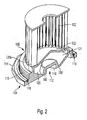
- FIG. 2 shows the oil filter device 100 in a sectional view, an isometric view obliquely from below is in FIG. 3 shown.
- the filter element 102, the lid portion 104 and the oil drain 112 are constructed structurally in common.
- the lid portion 104 of the oil filter device 100 is preferably made of plastic.
- the lid portion 104 is a Kunststoffsoff injection molded part made of a thermoplastic material, optionally fiber reinforced.
- the lid region 104 may also be designed as a sheet-metal component, for example of an aluminum alloy, or comprise both metal and plastic.
- the cover area 104 is disk-shaped and has an inwardly projecting collar with a connection geometry 116 for connecting the oil filter device 100 with a corresponding connection geometry of an oil reservoir.
- the connecting geometry 116 is an external thread, by means of which the oil filter device 100 can be screwed into an opening of an oil reservoir, in particular an oil pan, which has a corresponding internal thread.
- the connection geometry 116 may for example also be part of a bayonet closure.
- a groove 118 is provided for receiving a seal.
- the groove 118 serves to receive a conventional O-ring seal 119, which seals oil-tightly between the oil filter device 100 and the oil reservoir when the oil filter device 100 is connected to the oil reservoir.
- the lid region 104 has an engagement geometry 114 for a tool for inserting and / or removing the oil filter device 100.
- the attack geometry 114 is executed as a 12-Kant.
- the engagement geometry 114 may also have another convenient shape.
- the engagement geometry 114 may also be suitable for manual operation without tools.
- the engagement geometry 114 may include knurling.
- the lid region 104 has a pointed hood-like region 122, which comprises bypass openings 120a, 120b, 120c for draining off old oil, bypassing the filter element 102.
- the apex-like region 122 covers a chamber 121 to which access through the bypass openings 120a, 120b, 120c.
- the filter element 102 Radially on the inside of the collar with the connection geometry 116 and axially within the bypass openings 120a, 120b, 120c, the filter element 102 is connected to the lid portion 104.
- the filter element 102 is hollow-cylindrical or annular and enclosed at its end facing away from the cover region 104 with an annular-disk-shaped plastic part.
- this component can also be in another suitable material, for. B. sheet metal or, as today already prior art, without separate component in the filter element 102 integrated from the same material as the filter itself (compressed, oil-tight filter fleece) executed.
- the filter element 102 with the lid portion 104 and the annular disk-shaped plastic part is firmly potted or glued.
- an oil drain 112 is provided in the lid portion 104, which is closed with a destructible disposable closure 106.
- the oil drain 112 with one-way closure 106 is realized in the present case in that the cover region 104 has a predetermined breaking point 108 between the closure 106 and the further cover region 104.
- the predetermined breaking point 108 is designed so that the closure 106 closes securely and tightly during operation of the motor vehicle, but is releasable for an oil change.
- the predetermined breaking point is formed by an inner and / or outer weakening of the cover region 104.
- an annular-groove-shaped weakening of the cover region 104 is provided on the outside to form the predetermined breaking point 108.
- the lid region 104 is provided with a funnel-shaped region 105, which supports the formation of the predetermined breaking point 108 and at the same time ensures an easy and complete emptying of the oil reservoir when the oil drain 112 is open.
- the funnel-shaped region 105 extends approximately over the entire thickness of the lid portion 104.
- the oil drain 112 has a defined opening area, so that a defined flow is ensured when draining the oil.
- the predetermined breaking point 108 may also have another, for example, an oval or polygonal shape.
- the disposable closure 106 has an attack geometry 110 for a tool for removing the closure 106.
- this attack geometry 110 is designed as a hexagon socket.
- the engagement geometry 110 may also have another convenient shape, such as torx, slot, or phillips.
- the engagement geometry 110 may also be suitable for manual operation without a tool.
- the engagement geometry 110 may include a tear-off ring.
- a suitable tool can be attached to the attack geometry 110 and the closure 106 can be unscrewed or broken, so that old oil can enter the chamber 121 through the bypass openings 120a, 120b, 120c and drain through the oil drain 112.
- a complete drainage of old oil is supported by the bevel of the area surrounding the oil drain 112 and by the pointed hood-like configuration of the area 122.
- a suitable tool can be attached to the engagement geometry 114 and the oil filter device 100 can be removed from the oil reservoir.
- the old oil filter device 100 is discarded and a new oil filter device 100 is used using the appropriate tool, the oil drain 112 is closed with a closure 106, which is clean and pre-assembled with a new seal. Finally, new oil is filled into the oil reservoir.
- the filter element 102 when the filter element 102 is associated with the suction side of an oil pump, since the filter element 102 can then take over a protective function for the oil pump, so that a separate intake protection can be omitted.
- the previously required cleaning and re-insertion of a oily oil drain plug with new seal can be omitted.
Landscapes
- Chemical & Material Sciences (AREA)
- Chemical Kinetics & Catalysis (AREA)
- Engineering & Computer Science (AREA)
- Mechanical Engineering (AREA)
- General Engineering & Computer Science (AREA)
- Lubrication Details And Ventilation Of Internal Combustion Engines (AREA)
Description
- Die Erfindung betrifft eine Ölfilter-Einrichtung, insbesondere für eine Kraftfahrzeug-Brennkraftmaschine, umfassend ein Fitter-Eiement sowie einen Deckelbereich.
- Ölfilter werden verwendet, um das Schmieröl von Kraftfahrzeug-Brennkraftmaschinen zu reinigen. Ein üblicher Ölfilter geht beispielsweise aus der
DE 39. 03 675 A1 hervor. Dieser Ölfilter weist einen ringförmigen Filtereinsatz auf, der in einem topfförmigen Filtergehäuse angeordnet ist, umfasst eine Vielzahl von gesonderten Bauteilen und ist im Bereich der Brennkraftmaschinen-Peripherie angeordnet. - In regelmäßigen Zeitabständen muss das Schmieröl der Kraftfahrzeug-Brennkraftmaschine gewechselt werden. Dabei ist insbesondere bei Kraftfahrzeugen in der Regel auch der Filter-Einsatz zu wechseln. Bei einem üblichen Ölfilter, wie er aus der
DE 39 03 675 A1 hervorgeht, wird der Filtereinsatz im Filtergehäuse gewechselt, während ein Ablassen des Öls an anderer Stelle, üblicherweise mittels einer Ölablassöffnung im Bereich einer Ölwanne, erfolgt. Eine solche übliche Ölablassvorrichtung für Ölwannen von Kraftfahrzeug-Brennkräftmaschinen geht aus derDE 1 835 652 U hervor. - Weiter ist aus dem US Patent
US 6,616,838 eine Ölfilter-Einrichtung, insbesondere für eine Kraftfahrzeug-Brennkraftmaschine bekannt. Die Ölfilter-Einrichtung umfasst ein Filter-Element sowie einen Deckelbereich. Im Deckelbereich ist ein mittels eines zerstörbaren Einweg-Verschlusses verschlossener Ölablass vorgesehen. - Bei einem Ölwechsel sind demzufolge mehrere Arbeitsschritte an unterschiedlichen Orten auszuführen: Altes Öl ist an der Ölwanne abzulassen, im Bereich der Brennkraftmaschinen-Peripherie ist der Ölfilter zu wechseln, die Ölablassöffnung ist wieder zu schließen, wobei ein Verschlusselement zu reinigen und mit einem neuen Dichtmittel zu versehen ist, frisches Öl ist durch eine Öleinfüllöffnung einzufüllen. Damit verbunden sind ein beträchtlicher Bauraumaufwand, ein erhöhtes Gewicht, erhöhte Kosten sowie ein erhöhter Serviceaufwand.
- Aufgabe der Erfindung ist es daher, eine eingangs genannte Ölfilter-Einrichtung bereit zu stellen, die weniger Bauraum beansprucht, deren Gewicht reduziert ist, die günstiger ist und die einen vereinfachten Ölwechsel ermöglicht.
- Die Lösung der Aufgabe erfolgt mit einer Ölfilter-Einrichtung mit den Merkmalen des Anspruchs 1, indem im Deckelbereich der Ölfilter-Einrichtung ein mittels eines zerstörbaren Einweg-Verschlusses verschlossener Ölablass vorgesehen ist. Damit kann ein Ablassen alten Öls an der Ölfilter-Einrichtung selbst erfolgen, sodass die bei einem Ölwechsel erforderlichen Arbeitsschritte räumlich konzentriert ausgeführt werden können.
- Besonders zu bevorzugende Ausführungen und Weiterbildungen der Erfindung sind Gegenstand der Unteransprüche.
- Vorzugsweise sind bei der erfindungsgemäßen Ölfilter-Einrichtung der Deckelbereich und der Einweg-Verschluss einstückig als gemeinsames Bauteil ausgeführt und es ist zwischen Deckelbereich und Einweg-Verschluss eine Sollbruchstelle vorgesehen. Damit weist der Deckelbereich mit Ölablass und Einweg-Verschluss eine sehr einfache technische Gestalt auf und der Deckelbereich kann besonders kostengünstig hergestellt werden.
- Sehr vorteilhaft ist es, wenn der Einweg-Verschluss eine erste Angriffsgeometrie zum Entfernen des Einweg-Verschlusses aufweist. Damit kann der Einvireg-Verschluss beispielsweise von Hand, gegebenenfalls unter Zuhilfenahme eines entsprechenden Werkzeugs, entfernt werden, wobei jedoch auch ein automatisiertes Entfernen möglich ist.
- Bevorzugt ist es, wenn der Deckelbereich eine Verbindungs-Geometrie zur Verbindung der Ölfilter-Einrichtung mit einer korrespondierenden Verbindungs-Geometrie eines Ölreservoirs aufweist, sodass die Ölfilter-Einrichtung lösbar und zugleich öldicht mit dem Ölreservoir verbunden werden kann.
- Als vorteilhaft wird es zudem angesehen, wenn der Deckelbereich der Ölfilter-Einrichtung eine zweite Angriffsgeometrie zum Einsetzen und/oder Entfernen der Ölfilter-Einrichtung aufweist. Damit kann die Ölfilter-Einrichtung beispielsweise von Hand, gegebenenfalls unter Zuhilfenahme eines entsprechenden Werkzeugs, eingesetzt und/oder entfernt werden, wobei jedoch auch ein automatisiertes Einsetzen und/oder Entfernen möglich ist.
- Zweckmäßigerweise ist der Deckelbereich innenseitig zum Ölablass hin abgeschrägt, um beim Ablassen von altem Öl ein möglichst zügiges und vollständiges Ablaufen zu gewährleisten.
- Einem besonders bevorzugten Ausführungsbeispiel zufolge weist die erfindungsgemäße Ölfilter-Einrichtung Bypass-Öffnungen zum Ablassen von altem Öl unter Umgehung des Filter-Elements auf. Damit wird erreicht, dass altes Öl beim Ablassen nicht das Filter-Element durchströmen muss.
- Sehr günstig ist es, wenn der Deckelbereich axial innenseitig einen spitzhaubenartigen Bereich aufweist, der die Bypass-Öffnungen umfasst. Damit wird ebenfalls beim Ablassen von altem Öl ein möglichst zügiges und vollständiges Ablaufen unterstützt.
- Nachfolgend sind besonders zu bevorzugende Ausführungsbeispiele der Erfindung unter Bezugnahme auf Figuren näher erläutert, dabei zeigen schematisch und beispielhaft
- Figur 1
- eine Ölfilter-Einrichtung für eine Kraftfahrzeug-Brennkraftmaschine mit einem Filter-Element und einem Deckelbereich mit Ölablass und Einweg-Verschluss in isometrischer Ansicht von schräg oben,
- Figur 2
- eine Ölfilter-Einrichtung für eine Kraftfahrzeug-Brennkraftmaschine mit einem Filter-Element und einem Deckelbereich mit Ölablass und Einweg-Verschluss in Schnittdarstellung und
- Figur 3
- eine Ölfilter-Einrichtung für eine Kraftfahrzeug-Brennkraftmaschine mit einem Filter-Element und einem Deckelbereich mit Ölablass und Einweg-Verschluss in isometrischer Ansicht von schräg unten.
-
Figur 1 zeigt eine Ölfilter-Einrichtung 100 für eine Kraftfahrzeug-Brennkraftmaschine mit einem Filter-Element 102 und einem Deckelbereich 104 mit Ölablass 112 und Einweg-Verschluss 106 in isometrischer Ansicht von schräg oben,Figur 2 zeigt die Ölfilter-Einrichtung 100 in Schnittdarstellung, eine isometrische Ansicht von schräg unten ist inFigur 3 dargestellt. - In der Ölfilter-Einrichtung 100 sind das Filter-Element 102, der Deckelbereich 104 und der Ölablass 112 baulich gemeinsam ausgeführt.
- Der Deckelbereich 104 der Ölfilter-Einrichtung 100 ist vorzugsweise aus Kunststoff hergestellt. Beispielsweise ist der Deckelbereich 104 ein Kunstsoff-Spritzgussteil aus einem thermoplastischen Kunststoff, gegebenenfalls Faserverstärkt. Alternativ kann der Deckelbereich 104 auch als Blechbauteil, beispielsweise aus einer Aluminiumlegierung, ausgeführt sein oder sowohl Metall als auch Kunststoff umfassen.
- Der Deckelbereich 104 ist scheibenförmig ausgestaltet und weist einen nach innen ragenden Bund mit einer Verbindungs-Geometrie 116 zur Verbindung der Ölfilter-Einrichtung 100 mit einer korrespondierenden Verbindungs-Geometrie eines Ölreservoirs auf. Vorliegend ist die Verbindüngs-Geometrie 116 ein Außengewinde, mittels dem die Ölfilter-Einrichtung 100 in eine Öffnung eines Ölreservoirs, wie insbesondere Ölwanne, eingeschraubt werden kann, die ein korrespondierendes Innengewinde aufweist. Alternativ kann die Verbindungs-Geometrie 116 beispielsweise auch Teil eines Bajonettverschlusses sein. Radial außenseitig des Bunds mit der Verbindungs-Geometrie 116 ist zunächst eine Nut 118 zur Aufnahme einer Dichtung vorgesehen. Vorliegend dient die Nut 118 zur Aufnahme einer üblichen O-Ringdichtung 119, die zwischen Ölfilter-Einrichtung 100 und Ölreservoir öldicht dichtet, wenn die Ölfilter-Einrichtung 100 mit dem Ölreservoir verbunden ist. Weiter radial außenseitig weist der Deckelbereich 104 eine Angriffsgeometrie 114 für ein Werkzeug zum Einsetzen und/oder Entfernen der Ölfilter-Einrichtung 100 auf. Im dargestellten Ausführungsbeispiel ist die Angriffsgeometrie 114 als 12-Kant ausgeführt. Jedoch kann die Angriffsgeometrie 114 auch eine andere zweckmäßige Form aufweisen. Alternativ oder zusätzlich kann die Angriffsgeometrie 114 auch für eine manuelle Betätigung ohne Werkzeug geeignet sein. Beispielsweise kann die Angriffsgeometrie 114 eine Rändelung umfassen.
- Axial innenseitig der Verbindungs-Geometrie 116 weist der Deckelbereich 104 einen spitzhaubenartigen Bereich 122 auf, der Bypass-Öffnungen 120a, 120b, 120c zum Ablassen von altem Öl unter Umgehung des Filter-Elements 102 umfasst. Der spitzhaubenartige Bereich 122 überdeckt eine Kammer 121, zu der die durch die Bypass-Öffnungen 120a, 120b, 120c einen Zugang bilden.
- Radial innenseitig des Bunds mit der Verbindungs-Geometrie 116 und axial innerhalb der Bypass-Öffnungen 120a, 120b, 120c ist das Filter-Element 102 mit dem Deckelbereich 104 verbunden. Das Filter-Element 102 ist wie üblich hohlzylindrisch bzw. ringförmig ausgeführt und an seinem dem Deckelbereich 104 abgewandten Ende mit einem ringscheibenförmigen Kunststoffteil eingefasst. Alternativ kann dieses Bauteil auch in einem anderen geeigneten Werkstoff, z. B. Blech ausgeführt sein oder, wie heute auch schon Stand der Technik, ohne separatem Bauteil im Filterelement 102 integriert aus dem gleichen Material wie der Filter selbst (verdichtetes, öldichtes Filtervlies) ausgeführt sein. Vorliegend ist das Filter-Element 102 mit dem Deckelbereich 104 und dem ringscheibenförmigen Kunststoffteil fest vergossen oder verklebt. Radial innenseitig des Filter-Elements 102 ist im Deckelbereich 104 ein Ölablass 112 vorgesehen, der mit einem zerstörbaren Einweg-Verschluss 106 verschlossen ist. Der Ölablass 112 mit Einweg-Verschluss 106 ist vorliegend realisiert, indem der Deckelbereich 104 zwischen dem Verschluss 106 und dem weiteren Deckelbereich 104 eine Sollbruchstelle 108 aufweist.
- Die Sollbruchstelle 108 ist so ausgeführt, dass der Verschluss 106 beim Betrieb des Kraftfahrzeugs sicher und dicht schließt, für einen Ölwechsel jedoch lösbar ist. Die Sollbruchstelle ist durch eine innen- und/oder außenseitig liegende Schwächung des Deckelbereichs 104 gebildet. Vorliegend ist zur Bildung der Sollbruchstelle 108 außenseitig eine ringnutförmige Schwächung des Deckelbereichs 104 vorgesehen. Innenseitig ist der Deckelbereich 104 mit einem trichterförmigen Bereich 105 versehen, der die Bildung der Sollbruchstelle 108 unterstützt und zugleich bei geöffnetem Ölablass 112 eine problemlose und vollständige Entleerung des Ölreservoirs gewährleistet. Der trichterförmige Bereich 105 erstreckt sich annähernd über die gesamte Dicke des Deckelbereichs 104. Der Ölablass 112 weist eine definierte Öffnungsfläche auf, sodass beim Ölablassen ein definierter Durchfluss gewährleistet ist. Die Sollbruchstelle 108 kann auch eine andere, beispielweise eine ovale oder polygone Form aufweisen.
- Außenseitig weist der Einweg-Verschluss 106 eine Angriffsgeometrie 110 für ein Werkzeug zum Entfernen des Verschlusses 106 auf. Im dargestellten Ausführungsbeispiel ist diese Angriffsgeometrie 110 als Innensechskant ausgeführt. Jedoch kann die Angriffsgeometrie 110 auch eine andere zweckmäßige Form, wie Torx, Schlitz oder Kreuzschlitz, aufweisen. Alternativ oder zusätzlich kann die Angriffsgeometrie 110 auch für eine manuelle Betätigung ohne Werkzeug geeignet sein. Beispielsweise kann die Angriffsgeometrie 110 einen Abreißring umfassen.
- Für einen Ölwechsel kann ein geeignetes Werkzeug an der Angriffsgeometrie 110 angesetzt und der Verschluss 106 herausgedreht oder -gebrochen werden, sodass durch die Bypass-Öffnungen 120a, 120b, 120c altes Öl in die Kammer 121 einlaufen und durch den Ölablass 112 ablaufen kann. Dabei wird ein vollständiges Ablaufen alten Öls durch die Abschrägung des den Ölablass 112 umgebenden Bereichs sowie durch die spitzhaubenartige Ausgestaltung des Bereichs 122 unterstützt.
- Nachfolgend kann ein geeignetes Werkzeug an der Angriffsgeometrie 114 angesetzt und die Ölfilter-Einrichtung 100 vom Ölreservoir entfernt werden. Die alte Ölfilter-Einrichtung 100 wird entsorgt und es wird unter Verwendung des geeigneten Werkzeugs eine neue Ölfilter-Einrichtung 100 eingesetzt, deren Ölablass 112 mit einem Verschluss 106 verschlossen ist, das sauber und mit einer neuen Dichtung vorkonfektioniert ist. Abschließend wird neues Öl in das Ölreservoir eingefüllt.
- Besonders vorteilhaft ist eine Verwendung der erfindungsgemäßen Ölfilter-Einrichtung 100, wenn das Filter-Element 102 der Saugseite einer Ölpumpe zugeordnet ist, da das Filter-Element 102 dann zusätzliche eine Schutzfunktion für die Ölpumpe übernehmen kann, sodass ein gesonderter Ansaugschutzfilter entfallen kann.
- Mit der erfindungsgemäßen Ölfilter-Einrichtung 100 kann das bisher erforderliche Reinigen und wieder Einsetzen einer verölten Ölablassschraube mit neuer Dichtung entfallen.
Claims (7)
- Ölfilter-Einrichtung (100), insbesondere für eine Kraftfahrzeug-Brennkraftmaschine, umfassend ein Filter-Element (102) sowie einen Deckelbereich (104), wobei im Deckelbereich (104) ein mittels eines zerstörbaren Einweg-Verschlusses (106) verschlossener Ölablass (112) vorgesehen ist, dadurch gekennzeichnet, dass
der Deckelbereich (104) und der Einweg-Verschluss (106) einstückig als gemeinsames Bauteil ausgeführt sind und zwischen Deckelbereich (104) und Einweg-Verschluss (106) eine Sollbruchstelle (108) vorgesehen ist. - Ölfilter-Einrichtung (100) nach Patentanspruch 1, dadurch gekennzeichnet, dass der Einweg-Verschluss (106) eine erste Angriffsgeometrie (110) zum Entfernen des Einweg-Verschlusses (106) aufweist.
- Ölfilter-Einrichtung (100) nach einem der vorhergehenden Ansprüche, dadurch gekennzeichnet, dass der Deckelbereich (104) eine Verbindungs-Geometrie (116) zur Verbindung der Ölfilter-Einrichtung (100) mit einer korrespondierenden Verbindungs-Geometrie eines Ölreservoirs aufweist.
- Ölfilter-Einrichtung (100) nach einem der vorhergehenden Ansprüche, dadurch gekennzeichnet, dass der Deckelbereich (104) eine zweite Angriffsgeometrie (114) zum Einsetzen und/oder Entfernen der Ölfilter-Einrichtung (100) aufweist.
- Ölfilter-Einrichtung (100) nach einem der vorhergehenden Ansprüche, dadurch gekennzeichnet, dass der Deckelbereich (104) innenseitig zum Ölablass (112) hin abgeschrägt ist (105).
- Ölfilter-Einrichtung (100) nach einem der vorhergehenden Ansprüche,
gekennzeichnet durch Bypass-Offnungen (120a, 120b, 120c) zum Ablassen von altem Öl unter Umgehung des Filter-Elements (102). - Ölfilter-Einrichtung (100) nach einem der vorhergehenden Ansprüche, dadurch gekennzeichnet, dass der Deckelbereich (104) axial innenseitig einen spitzhaubenartigen Bereich (122) aufweist, der die Bypass-Offnungen (120a, 120b, 120c) umfasst.
Applications Claiming Priority (2)
| Application Number | Priority Date | Filing Date | Title |
|---|---|---|---|
| DE102010015677A DE102010015677A1 (de) | 2010-04-21 | 2010-04-21 | Ölfilter-Einrichtung |
| PCT/EP2011/001069 WO2011131271A1 (de) | 2010-04-21 | 2011-03-04 | Ölfilter-einrichtung |
Publications (2)
| Publication Number | Publication Date |
|---|---|
| EP2561192A1 EP2561192A1 (de) | 2013-02-27 |
| EP2561192B1 true EP2561192B1 (de) | 2014-06-11 |
Family
ID=44021994
Family Applications (1)
| Application Number | Title | Priority Date | Filing Date |
|---|---|---|---|
| EP11709000.1A Not-in-force EP2561192B1 (de) | 2010-04-21 | 2011-03-04 | Ölfilter-einrichtung |
Country Status (6)
| Country | Link |
|---|---|
| US (1) | US8940165B2 (de) |
| EP (1) | EP2561192B1 (de) |
| CN (1) | CN102686839B (de) |
| DE (1) | DE102010015677A1 (de) |
| ES (1) | ES2476141T3 (de) |
| WO (1) | WO2011131271A1 (de) |
Families Citing this family (9)
| Publication number | Priority date | Publication date | Assignee | Title |
|---|---|---|---|---|
| DE102015003914B4 (de) | 2015-03-27 | 2024-01-04 | Mann+Hummel Gmbh | Verschlussdeckel für einen Flüssigkeitsfilter, Filterelement mit einem Verschlussdeckel und Filtereinrichtung mit einem solchen Filterelement |
| JP6459736B2 (ja) * | 2015-04-10 | 2019-01-30 | 株式会社デンソー | 電動パワーステアリング装置 |
| DE102015222431A1 (de) * | 2015-11-13 | 2017-05-18 | Mahle International Gmbh | Filtereinrichtung |
| USD844103S1 (en) * | 2017-01-18 | 2019-03-26 | Yoshida Tekko Kabushiki Kaisha | Filtration drum |
| DE102017003578A1 (de) * | 2017-04-12 | 2018-10-18 | Hydac Fluidcarecenter Gmbh | Vorrichtung zum Austauschen eines Filterelements |
| WO2021101756A1 (en) | 2019-11-18 | 2021-05-27 | Cummins Filtration Inc. | Low restriction air filter |
| US12496546B2 (en) | 2020-04-14 | 2025-12-16 | Cummins Filtration Inc. | Filter element with closed endcap forming a seal positioned at different axial distances |
| DE102020123586B4 (de) | 2020-09-10 | 2023-09-28 | Argo-Hytos Group Ag | Filterelement, Filtereinrichtung, Anordnung und Montageverfahren |
| DE102024137066A1 (de) * | 2024-12-11 | 2026-06-11 | Dr. Ing. H.C. F. Porsche Aktiengesellschaft | Ölfilter für ein Flüssigkühlsystem mit Sollbruchstelle und ein diesen aufweisendes Flüssigkühlsystem |
Family Cites Families (25)
| Publication number | Priority date | Publication date | Assignee | Title |
|---|---|---|---|---|
| US2372286A (en) * | 1940-10-12 | 1945-03-27 | Ind Wire Cloth Products Compan | Oil screen |
| US2524336A (en) * | 1945-03-16 | 1950-10-03 | Vokes Ltd | Filter |
| US2887229A (en) * | 1955-11-12 | 1959-05-19 | Maschf Augsburg Nuernberg Ag | Oil intake screening device for internal combustion engines |
| DE1835652U (de) | 1961-05-03 | 1961-07-27 | Maschf Augsburg Nuernberg Ag | Oelablassvorrichtung fuer oelwannen von verbrennungsmotoren oder getriebegehaeusen, insbesondere von kraftfahrzeugen |
| US3211291A (en) * | 1963-04-10 | 1965-10-12 | Marvin G Teutsch | Combination drain plug and screen |
| US3211256A (en) * | 1963-05-20 | 1965-10-12 | Marvin G Teutsch | Pan reservoir and closure |
| US3334775A (en) * | 1965-02-23 | 1967-08-08 | Klein | Gated can lid |
| US3773144A (en) * | 1972-11-13 | 1973-11-20 | E Hummel | Strainer arrangement for the oil sump of internal combustion engines |
| US3912633A (en) * | 1974-09-09 | 1975-10-14 | Arthur Delaney | Oil filter with pull tab drain |
| GB1581416A (en) * | 1978-05-06 | 1980-12-10 | Automotive Prod Co Ltd | Filter units |
| US4177529A (en) | 1978-08-18 | 1979-12-11 | Deere & Company | Filter wrench |
| SE439036B (sv) * | 1984-06-21 | 1985-05-28 | Runo Nord | Anordning vid demonterbara vetskebehallare, i synnerhet oljefilter |
| US4744328A (en) * | 1984-12-21 | 1988-05-17 | Lynn Stevens D | Sealant compositions and methods for use in detecting equipment tampering |
| US5044531A (en) * | 1986-08-11 | 1991-09-03 | Rhodes Jr Harold B | Bottle having spillage prevention |
| JPS6339442U (de) * | 1986-08-29 | 1988-03-14 | ||
| DE3903675A1 (de) | 1989-02-08 | 1990-08-09 | Knecht Filterwerke Gmbh | Oelfilter zum reinigen von schmieroel |
| US5588140A (en) * | 1993-03-15 | 1996-12-24 | Computer Network Technology Corporation | Transparent extension of peripheral from host |
| US5421223A (en) * | 1993-11-22 | 1995-06-06 | Wawrzyniak; Timothy J. | Oil filter cover |
| US5546979A (en) * | 1994-09-02 | 1996-08-20 | Clark Technology Systems, Inc. | Device for draining fluid from a container |
| US6199578B1 (en) * | 1995-12-01 | 2001-03-13 | C.H. & I. Technologies, Inc. | Device for draining fluid from a container |
| US6705270B1 (en) * | 2000-04-26 | 2004-03-16 | Basf Corporation | Oil pan module for internal combustion engines |
| US6585889B2 (en) * | 2000-06-01 | 2003-07-01 | Federal-Mogul World Wide Inc. | Transmission oil pan module having filter with integrated drain plug |
| US6616838B1 (en) * | 2001-04-20 | 2003-09-09 | Lazarus E. Harris | No-spill oil filter |
| US6672932B1 (en) * | 2002-01-14 | 2004-01-06 | Treasure Bay, Inc. | Actuatable toy containing deformable bladder |
| DE102004058885B4 (de) | 2004-12-06 | 2016-12-22 | Mann + Hummel Gmbh | Füssigkeitsfilter |
-
2010
- 2010-04-21 DE DE102010015677A patent/DE102010015677A1/de not_active Withdrawn
-
2011
- 2011-03-04 WO PCT/EP2011/001069 patent/WO2011131271A1/de not_active Ceased
- 2011-03-04 EP EP11709000.1A patent/EP2561192B1/de not_active Not-in-force
- 2011-03-04 CN CN201180005146.XA patent/CN102686839B/zh not_active Expired - Fee Related
- 2011-03-04 ES ES11709000.1T patent/ES2476141T3/es active Active
-
2012
- 2012-10-19 US US13/655,820 patent/US8940165B2/en not_active Expired - Fee Related
Also Published As
| Publication number | Publication date |
|---|---|
| CN102686839A (zh) | 2012-09-19 |
| US8940165B2 (en) | 2015-01-27 |
| US20130037478A1 (en) | 2013-02-14 |
| WO2011131271A1 (de) | 2011-10-27 |
| CN102686839B (zh) | 2015-07-08 |
| DE102010015677A1 (de) | 2011-10-27 |
| EP2561192A1 (de) | 2013-02-27 |
| ES2476141T3 (es) | 2014-07-11 |
Similar Documents
| Publication | Publication Date | Title |
|---|---|---|
| WO2011131271A1 (de) | Ölfilter-einrichtung | |
| DE102004058885B4 (de) | Füssigkeitsfilter | |
| EP3300786B1 (de) | Filtervorrichtung | |
| EP1131542B1 (de) | Flüssigkeitsfilter, insbesondere für öl oder kraftstoff einer brennkraftmaschine | |
| DE102007009352B4 (de) | Flüssigkeitsfilter | |
| DE112013005747B4 (de) | Filter, Filterelement, Filtergehäuse und Ablassvorrichtung eines Filters | |
| EP1110590A2 (de) | Flüssigkeitsfilter mit Ablass für Flüssigkeitsrückstände | |
| EP2918326B1 (de) | Filtereinrichtung und filtergehäusedeckel | |
| EP3096859B1 (de) | Filterelement | |
| EP2042693A1 (de) | Ölsammelgehäuse | |
| DE202006017614U1 (de) | Flüssigkeitsfilter mit verschmutzungsgeschützter Reinseite | |
| EP4048428B1 (de) | Abscheidevorrichtung zur abscheidung von flüssigkeit aus gas, insbesondere luft, und abscheidesystem einer maschine | |
| DE102015008328B4 (de) | Filteranschlusseinrichtung und Filtereinrichtung | |
| EP1811142A2 (de) | Ölwanne, insbesondere für eine Brennkraftmaschine | |
| EP3727643B1 (de) | Filterelement eines filters für flüssigkeit und filter | |
| EP2923045B1 (de) | Ölwannen-filterkombination, ölwanne und ablassvorrichtung einer ölwannen-filterkombination | |
| EP3727642B1 (de) | Filter mit einem ablassverschlusselement | |
| DE202008014615U1 (de) | Filtereinrichtung, insbesondere zur Flüssigkeitsfilterung in Brennkraftmaschinen | |
| WO2016008605A1 (de) | Ölfiltervorrichtung und gehäusedeckel und gehäusetopf einer ölfiltervorrichtung | |
| EP2283909B1 (de) | Ölfiltervorrichtung mit einer Entölungseinrichtung | |
| WO2016008776A1 (de) | Hohlfilterelement eines filters für fluid, filter und filtergehäuse | |
| EP1962991A1 (de) | Ölfiltereinrichtung für eine brennkraftmaschine | |
| DE102015003914B4 (de) | Verschlussdeckel für einen Flüssigkeitsfilter, Filterelement mit einem Verschlussdeckel und Filtereinrichtung mit einem solchen Filterelement | |
| DE202008015675U1 (de) | Wechselfilterelement | |
| DE19629628C1 (de) | Verschlußteil zum zeitweisen Verschließen eines kraftstoffenthaltenden Bauteils |
Legal Events
| Date | Code | Title | Description |
|---|---|---|---|
| PUAI | Public reference made under article 153(3) epc to a published international application that has entered the european phase |
Free format text: ORIGINAL CODE: 0009012 |
|
| 17P | Request for examination filed |
Effective date: 20120910 |
|
| AK | Designated contracting states |
Kind code of ref document: A1 Designated state(s): AL AT BE BG CH CY CZ DE DK EE ES FI FR GB GR HR HU IE IS IT LI LT LU LV MC MK MT NL NO PL PT RO RS SE SI SK SM TR |
|
| DAX | Request for extension of the european patent (deleted) | ||
| GRAP | Despatch of communication of intention to grant a patent |
Free format text: ORIGINAL CODE: EPIDOSNIGR1 |
|
| INTG | Intention to grant announced |
Effective date: 20140107 |
|
| GRAS | Grant fee paid |
Free format text: ORIGINAL CODE: EPIDOSNIGR3 |
|
| GRAA | (expected) grant |
Free format text: ORIGINAL CODE: 0009210 |
|
| AK | Designated contracting states |
Kind code of ref document: B1 Designated state(s): AL AT BE BG CH CY CZ DE DK EE ES FI FR GB GR HR HU IE IS IT LI LT LU LV MC MK MT NL NO PL PT RO RS SE SI SK SM TR |
|
| REG | Reference to a national code |
Ref country code: GB Ref legal event code: FG4D Free format text: NOT ENGLISH |
|
| REG | Reference to a national code |
Ref country code: CH Ref legal event code: EP |
|
| REG | Reference to a national code |
Ref country code: IE Ref legal event code: FG4D Free format text: LANGUAGE OF EP DOCUMENT: GERMAN |
|
| REG | Reference to a national code |
Ref country code: ES Ref legal event code: FG2A Ref document number: 2476141 Country of ref document: ES Kind code of ref document: T3 Effective date: 20140711 |
|
| REG | Reference to a national code |
Ref country code: AT Ref legal event code: REF Ref document number: 672374 Country of ref document: AT Kind code of ref document: T Effective date: 20140715 |
|
| REG | Reference to a national code |
Ref country code: DE Ref legal event code: R096 Ref document number: 502011003365 Country of ref document: DE Effective date: 20140724 |
|
| PG25 | Lapsed in a contracting state [announced via postgrant information from national office to epo] |
Ref country code: GR Free format text: LAPSE BECAUSE OF FAILURE TO SUBMIT A TRANSLATION OF THE DESCRIPTION OR TO PAY THE FEE WITHIN THE PRESCRIBED TIME-LIMIT Effective date: 20140912 Ref country code: FI Free format text: LAPSE BECAUSE OF FAILURE TO SUBMIT A TRANSLATION OF THE DESCRIPTION OR TO PAY THE FEE WITHIN THE PRESCRIBED TIME-LIMIT Effective date: 20140611 Ref country code: LT Free format text: LAPSE BECAUSE OF FAILURE TO SUBMIT A TRANSLATION OF THE DESCRIPTION OR TO PAY THE FEE WITHIN THE PRESCRIBED TIME-LIMIT Effective date: 20140611 Ref country code: NO Free format text: LAPSE BECAUSE OF FAILURE TO SUBMIT A TRANSLATION OF THE DESCRIPTION OR TO PAY THE FEE WITHIN THE PRESCRIBED TIME-LIMIT Effective date: 20140911 |
|
| REG | Reference to a national code |
Ref country code: NL Ref legal event code: VDEP Effective date: 20140611 |
|
| REG | Reference to a national code |
Ref country code: LT Ref legal event code: MG4D |
|
| PG25 | Lapsed in a contracting state [announced via postgrant information from national office to epo] |
Ref country code: SE Free format text: LAPSE BECAUSE OF FAILURE TO SUBMIT A TRANSLATION OF THE DESCRIPTION OR TO PAY THE FEE WITHIN THE PRESCRIBED TIME-LIMIT Effective date: 20140611 Ref country code: RS Free format text: LAPSE BECAUSE OF FAILURE TO SUBMIT A TRANSLATION OF THE DESCRIPTION OR TO PAY THE FEE WITHIN THE PRESCRIBED TIME-LIMIT Effective date: 20140611 Ref country code: LV Free format text: LAPSE BECAUSE OF FAILURE TO SUBMIT A TRANSLATION OF THE DESCRIPTION OR TO PAY THE FEE WITHIN THE PRESCRIBED TIME-LIMIT Effective date: 20140611 Ref country code: HR Free format text: LAPSE BECAUSE OF FAILURE TO SUBMIT A TRANSLATION OF THE DESCRIPTION OR TO PAY THE FEE WITHIN THE PRESCRIBED TIME-LIMIT Effective date: 20140611 |
|
| PG25 | Lapsed in a contracting state [announced via postgrant information from national office to epo] |
Ref country code: SK Free format text: LAPSE BECAUSE OF FAILURE TO SUBMIT A TRANSLATION OF THE DESCRIPTION OR TO PAY THE FEE WITHIN THE PRESCRIBED TIME-LIMIT Effective date: 20140611 Ref country code: RO Free format text: LAPSE BECAUSE OF FAILURE TO SUBMIT A TRANSLATION OF THE DESCRIPTION OR TO PAY THE FEE WITHIN THE PRESCRIBED TIME-LIMIT Effective date: 20140611 Ref country code: EE Free format text: LAPSE BECAUSE OF FAILURE TO SUBMIT A TRANSLATION OF THE DESCRIPTION OR TO PAY THE FEE WITHIN THE PRESCRIBED TIME-LIMIT Effective date: 20140611 Ref country code: PT Free format text: LAPSE BECAUSE OF FAILURE TO SUBMIT A TRANSLATION OF THE DESCRIPTION OR TO PAY THE FEE WITHIN THE PRESCRIBED TIME-LIMIT Effective date: 20141013 Ref country code: CZ Free format text: LAPSE BECAUSE OF FAILURE TO SUBMIT A TRANSLATION OF THE DESCRIPTION OR TO PAY THE FEE WITHIN THE PRESCRIBED TIME-LIMIT Effective date: 20140611 |
|
| PG25 | Lapsed in a contracting state [announced via postgrant information from national office to epo] |
Ref country code: PL Free format text: LAPSE BECAUSE OF FAILURE TO SUBMIT A TRANSLATION OF THE DESCRIPTION OR TO PAY THE FEE WITHIN THE PRESCRIBED TIME-LIMIT Effective date: 20140611 Ref country code: NL Free format text: LAPSE BECAUSE OF FAILURE TO SUBMIT A TRANSLATION OF THE DESCRIPTION OR TO PAY THE FEE WITHIN THE PRESCRIBED TIME-LIMIT Effective date: 20140611 Ref country code: IS Free format text: LAPSE BECAUSE OF FAILURE TO SUBMIT A TRANSLATION OF THE DESCRIPTION OR TO PAY THE FEE WITHIN THE PRESCRIBED TIME-LIMIT Effective date: 20141011 |
|
| REG | Reference to a national code |
Ref country code: DE Ref legal event code: R097 Ref document number: 502011003365 Country of ref document: DE |
|
| PLBE | No opposition filed within time limit |
Free format text: ORIGINAL CODE: 0009261 |
|
| STAA | Information on the status of an ep patent application or granted ep patent |
Free format text: STATUS: NO OPPOSITION FILED WITHIN TIME LIMIT |
|
| PG25 | Lapsed in a contracting state [announced via postgrant information from national office to epo] |
Ref country code: DK Free format text: LAPSE BECAUSE OF FAILURE TO SUBMIT A TRANSLATION OF THE DESCRIPTION OR TO PAY THE FEE WITHIN THE PRESCRIBED TIME-LIMIT Effective date: 20140611 |
|
| 26N | No opposition filed |
Effective date: 20150312 |
|
| REG | Reference to a national code |
Ref country code: DE Ref legal event code: R097 Ref document number: 502011003365 Country of ref document: DE Effective date: 20150312 |
|
| PG25 | Lapsed in a contracting state [announced via postgrant information from national office to epo] |
Ref country code: SI Free format text: LAPSE BECAUSE OF FAILURE TO SUBMIT A TRANSLATION OF THE DESCRIPTION OR TO PAY THE FEE WITHIN THE PRESCRIBED TIME-LIMIT Effective date: 20140611 |
|
| PG25 | Lapsed in a contracting state [announced via postgrant information from national office to epo] |
Ref country code: MC Free format text: LAPSE BECAUSE OF FAILURE TO SUBMIT A TRANSLATION OF THE DESCRIPTION OR TO PAY THE FEE WITHIN THE PRESCRIBED TIME-LIMIT Effective date: 20140611 Ref country code: LU Free format text: LAPSE BECAUSE OF FAILURE TO SUBMIT A TRANSLATION OF THE DESCRIPTION OR TO PAY THE FEE WITHIN THE PRESCRIBED TIME-LIMIT Effective date: 20150304 |
|
| REG | Reference to a national code |
Ref country code: CH Ref legal event code: PL |
|
| REG | Reference to a national code |
Ref country code: IE Ref legal event code: MM4A |
|
| PG25 | Lapsed in a contracting state [announced via postgrant information from national office to epo] |
Ref country code: LI Free format text: LAPSE BECAUSE OF NON-PAYMENT OF DUE FEES Effective date: 20150331 Ref country code: CH Free format text: LAPSE BECAUSE OF NON-PAYMENT OF DUE FEES Effective date: 20150331 Ref country code: IE Free format text: LAPSE BECAUSE OF NON-PAYMENT OF DUE FEES Effective date: 20150304 |
|
| REG | Reference to a national code |
Ref country code: FR Ref legal event code: PLFP Year of fee payment: 6 |
|
| PG25 | Lapsed in a contracting state [announced via postgrant information from national office to epo] |
Ref country code: MT Free format text: LAPSE BECAUSE OF FAILURE TO SUBMIT A TRANSLATION OF THE DESCRIPTION OR TO PAY THE FEE WITHIN THE PRESCRIBED TIME-LIMIT Effective date: 20140611 |
|
| REG | Reference to a national code |
Ref country code: FR Ref legal event code: PLFP Year of fee payment: 7 |
|
| REG | Reference to a national code |
Ref country code: AT Ref legal event code: MM01 Ref document number: 672374 Country of ref document: AT Kind code of ref document: T Effective date: 20160304 |
|
| PG25 | Lapsed in a contracting state [announced via postgrant information from national office to epo] |
Ref country code: BG Free format text: LAPSE BECAUSE OF FAILURE TO SUBMIT A TRANSLATION OF THE DESCRIPTION OR TO PAY THE FEE WITHIN THE PRESCRIBED TIME-LIMIT Effective date: 20140611 Ref country code: HU Free format text: LAPSE BECAUSE OF FAILURE TO SUBMIT A TRANSLATION OF THE DESCRIPTION OR TO PAY THE FEE WITHIN THE PRESCRIBED TIME-LIMIT; INVALID AB INITIO Effective date: 20110304 Ref country code: SM Free format text: LAPSE BECAUSE OF FAILURE TO SUBMIT A TRANSLATION OF THE DESCRIPTION OR TO PAY THE FEE WITHIN THE PRESCRIBED TIME-LIMIT Effective date: 20140611 |
|
| PG25 | Lapsed in a contracting state [announced via postgrant information from national office to epo] |
Ref country code: CY Free format text: LAPSE BECAUSE OF FAILURE TO SUBMIT A TRANSLATION OF THE DESCRIPTION OR TO PAY THE FEE WITHIN THE PRESCRIBED TIME-LIMIT Effective date: 20140611 |
|
| PG25 | Lapsed in a contracting state [announced via postgrant information from national office to epo] |
Ref country code: BE Free format text: LAPSE BECAUSE OF NON-PAYMENT OF DUE FEES Effective date: 20150331 |
|
| PG25 | Lapsed in a contracting state [announced via postgrant information from national office to epo] |
Ref country code: TR Free format text: LAPSE BECAUSE OF FAILURE TO SUBMIT A TRANSLATION OF THE DESCRIPTION OR TO PAY THE FEE WITHIN THE PRESCRIBED TIME-LIMIT Effective date: 20140611 Ref country code: AT Free format text: LAPSE BECAUSE OF NON-PAYMENT OF DUE FEES Effective date: 20160304 |
|
| REG | Reference to a national code |
Ref country code: FR Ref legal event code: PLFP Year of fee payment: 8 |
|
| PG25 | Lapsed in a contracting state [announced via postgrant information from national office to epo] |
Ref country code: MK Free format text: LAPSE BECAUSE OF FAILURE TO SUBMIT A TRANSLATION OF THE DESCRIPTION OR TO PAY THE FEE WITHIN THE PRESCRIBED TIME-LIMIT Effective date: 20140611 |
|
| PG25 | Lapsed in a contracting state [announced via postgrant information from national office to epo] |
Ref country code: AL Free format text: LAPSE BECAUSE OF FAILURE TO SUBMIT A TRANSLATION OF THE DESCRIPTION OR TO PAY THE FEE WITHIN THE PRESCRIBED TIME-LIMIT Effective date: 20140611 |
|
| PGFP | Annual fee paid to national office [announced via postgrant information from national office to epo] |
Ref country code: GB Payment date: 20200325 Year of fee payment: 10 Ref country code: DE Payment date: 20200313 Year of fee payment: 10 Ref country code: IT Payment date: 20200325 Year of fee payment: 10 |
|
| PGFP | Annual fee paid to national office [announced via postgrant information from national office to epo] |
Ref country code: FR Payment date: 20200324 Year of fee payment: 10 |
|
| PGFP | Annual fee paid to national office [announced via postgrant information from national office to epo] |
Ref country code: ES Payment date: 20200421 Year of fee payment: 10 |
|
| REG | Reference to a national code |
Ref country code: DE Ref legal event code: R119 Ref document number: 502011003365 Country of ref document: DE |
|
| GBPC | Gb: european patent ceased through non-payment of renewal fee |
Effective date: 20210304 |
|
| PG25 | Lapsed in a contracting state [announced via postgrant information from national office to epo] |
Ref country code: DE Free format text: LAPSE BECAUSE OF NON-PAYMENT OF DUE FEES Effective date: 20211001 Ref country code: GB Free format text: LAPSE BECAUSE OF NON-PAYMENT OF DUE FEES Effective date: 20210304 Ref country code: FR Free format text: LAPSE BECAUSE OF NON-PAYMENT OF DUE FEES Effective date: 20210331 |
|
| PG25 | Lapsed in a contracting state [announced via postgrant information from national office to epo] |
Ref country code: IT Free format text: LAPSE BECAUSE OF NON-PAYMENT OF DUE FEES Effective date: 20210304 |
|
| REG | Reference to a national code |
Ref country code: ES Ref legal event code: FD2A Effective date: 20220523 |
|
| PG25 | Lapsed in a contracting state [announced via postgrant information from national office to epo] |
Ref country code: ES Free format text: LAPSE BECAUSE OF NON-PAYMENT OF DUE FEES Effective date: 20210305 |
|
| P01 | Opt-out of the competence of the unified patent court (upc) registered |
Effective date: 20230502 |