EP2561121B1 - Système d'électrolyse - Google Patents
Système d'électrolyse Download PDFInfo
- Publication number
- EP2561121B1 EP2561121B1 EP11772747.9A EP11772747A EP2561121B1 EP 2561121 B1 EP2561121 B1 EP 2561121B1 EP 11772747 A EP11772747 A EP 11772747A EP 2561121 B1 EP2561121 B1 EP 2561121B1
- Authority
- EP
- European Patent Office
- Prior art keywords
- space
- brine
- electrode plate
- cells
- ion exchange
- Prior art date
- Legal status (The legal status is an assumption and is not a legal conclusion. Google has not performed a legal analysis and makes no representation as to the accuracy of the status listed.)
- Active
Links
- 239000012528 membrane Substances 0.000 claims description 93
- 239000012267 brine Substances 0.000 claims description 77
- HPALAKNZSZLMCH-UHFFFAOYSA-M sodium;chloride;hydrate Chemical compound O.[Na+].[Cl-] HPALAKNZSZLMCH-UHFFFAOYSA-M 0.000 claims description 77
- XLYOFNOQVPJJNP-UHFFFAOYSA-N water Substances O XLYOFNOQVPJJNP-UHFFFAOYSA-N 0.000 claims description 62
- 239000000126 substance Substances 0.000 claims description 42
- 239000013505 freshwater Substances 0.000 claims description 30
- 239000002585 base Substances 0.000 claims description 27
- 239000002253 acid Substances 0.000 claims description 23
- 150000002500 ions Chemical class 0.000 claims description 23
- 239000000243 solution Substances 0.000 claims description 16
- 230000002378 acidificating effect Effects 0.000 claims description 11
- 238000004891 communication Methods 0.000 claims description 11
- 238000000034 method Methods 0.000 claims description 9
- 238000004140 cleaning Methods 0.000 claims description 7
- 238000004519 manufacturing process Methods 0.000 claims description 7
- 150000001447 alkali salts Chemical class 0.000 claims description 6
- 238000005342 ion exchange Methods 0.000 claims 13
- 238000009826 distribution Methods 0.000 description 12
- FAPWRFPIFSIZLT-UHFFFAOYSA-M Sodium chloride Chemical compound [Na+].[Cl-] FAPWRFPIFSIZLT-UHFFFAOYSA-M 0.000 description 8
- 239000000047 product Substances 0.000 description 8
- 238000010276 construction Methods 0.000 description 7
- 239000012530 fluid Substances 0.000 description 6
- 239000011780 sodium chloride Substances 0.000 description 5
- 230000005684 electric field Effects 0.000 description 4
- 150000003839 salts Chemical class 0.000 description 4
- 239000007787 solid Substances 0.000 description 4
- HEMHJVSKTPXQMS-UHFFFAOYSA-M Sodium hydroxide Chemical compound [OH-].[Na+] HEMHJVSKTPXQMS-UHFFFAOYSA-M 0.000 description 3
- 239000003929 acidic solution Substances 0.000 description 3
- 238000013461 design Methods 0.000 description 3
- 238000005868 electrolysis reaction Methods 0.000 description 3
- 239000003014 ion exchange membrane Substances 0.000 description 3
- 150000001450 anions Chemical class 0.000 description 2
- 230000015572 biosynthetic process Effects 0.000 description 2
- 150000001768 cations Chemical class 0.000 description 2
- QWPPOHNGKGFGJK-UHFFFAOYSA-N hypochlorous acid Chemical compound ClO QWPPOHNGKGFGJK-UHFFFAOYSA-N 0.000 description 2
- 238000012545 processing Methods 0.000 description 2
- 230000001954 sterilising effect Effects 0.000 description 2
- 150000007513 acids Chemical class 0.000 description 1
- 230000002411 adverse Effects 0.000 description 1
- 239000012670 alkaline solution Substances 0.000 description 1
- 239000003011 anion exchange membrane Substances 0.000 description 1
- 239000007864 aqueous solution Substances 0.000 description 1
- 230000009286 beneficial effect Effects 0.000 description 1
- 238000005341 cation exchange Methods 0.000 description 1
- 238000011109 contamination Methods 0.000 description 1
- 238000005260 corrosion Methods 0.000 description 1
- 230000007797 corrosion Effects 0.000 description 1
- 230000001236 detergent effect Effects 0.000 description 1
- 238000010586 diagram Methods 0.000 description 1
- 230000000694 effects Effects 0.000 description 1
- 239000003792 electrolyte Substances 0.000 description 1
- 239000004519 grease Substances 0.000 description 1
- 238000012986 modification Methods 0.000 description 1
- 230000004048 modification Effects 0.000 description 1
- 230000000414 obstructive effect Effects 0.000 description 1
- 238000005192 partition Methods 0.000 description 1
- 239000012466 permeate Substances 0.000 description 1
- 229920002635 polyurethane Polymers 0.000 description 1
- 239000004814 polyurethane Substances 0.000 description 1
- 230000003389 potentiating effect Effects 0.000 description 1
- 230000001105 regulatory effect Effects 0.000 description 1
- 239000012266 salt solution Substances 0.000 description 1
- 238000011012 sanitization Methods 0.000 description 1
- 238000004513 sizing Methods 0.000 description 1
- 125000006850 spacer group Chemical group 0.000 description 1
- 239000003206 sterilizing agent Substances 0.000 description 1
- 238000012546 transfer Methods 0.000 description 1
Images


Classifications
-
- C—CHEMISTRY; METALLURGY
- C25—ELECTROLYTIC OR ELECTROPHORETIC PROCESSES; APPARATUS THEREFOR
- C25B—ELECTROLYTIC OR ELECTROPHORETIC PROCESSES FOR THE PRODUCTION OF COMPOUNDS OR NON-METALS; APPARATUS THEREFOR
- C25B9/00—Cells or assemblies of cells; Constructional parts of cells; Assemblies of constructional parts, e.g. electrode-diaphragm assemblies; Process-related cell features
- C25B9/70—Assemblies comprising two or more cells
-
- C—CHEMISTRY; METALLURGY
- C02—TREATMENT OF WATER, WASTE WATER, SEWAGE, OR SLUDGE
- C02F—TREATMENT OF WATER, WASTE WATER, SEWAGE, OR SLUDGE
- C02F1/00—Treatment of water, waste water, or sewage
- C02F1/46—Treatment of water, waste water, or sewage by electrochemical methods
- C02F1/461—Treatment of water, waste water, or sewage by electrochemical methods by electrolysis
- C02F1/46104—Devices therefor; Their operating or servicing
- C02F1/4618—Devices therefor; Their operating or servicing for producing "ionised" acidic or basic water
-
- C—CHEMISTRY; METALLURGY
- C25—ELECTROLYTIC OR ELECTROPHORETIC PROCESSES; APPARATUS THEREFOR
- C25B—ELECTROLYTIC OR ELECTROPHORETIC PROCESSES FOR THE PRODUCTION OF COMPOUNDS OR NON-METALS; APPARATUS THEREFOR
- C25B1/00—Electrolytic production of inorganic compounds or non-metals
-
- C—CHEMISTRY; METALLURGY
- C02—TREATMENT OF WATER, WASTE WATER, SEWAGE, OR SLUDGE
- C02F—TREATMENT OF WATER, WASTE WATER, SEWAGE, OR SLUDGE
- C02F1/00—Treatment of water, waste water, or sewage
- C02F1/46—Treatment of water, waste water, or sewage by electrochemical methods
- C02F1/461—Treatment of water, waste water, or sewage by electrochemical methods by electrolysis
- C02F1/46104—Devices therefor; Their operating or servicing
- C02F1/4618—Devices therefor; Their operating or servicing for producing "ionised" acidic or basic water
- C02F2001/46185—Devices therefor; Their operating or servicing for producing "ionised" acidic or basic water only anodic or acidic water, e.g. for oxidizing or sterilizing
-
- C—CHEMISTRY; METALLURGY
- C02—TREATMENT OF WATER, WASTE WATER, SEWAGE, OR SLUDGE
- C02F—TREATMENT OF WATER, WASTE WATER, SEWAGE, OR SLUDGE
- C02F1/00—Treatment of water, waste water, or sewage
- C02F1/46—Treatment of water, waste water, or sewage by electrochemical methods
- C02F1/461—Treatment of water, waste water, or sewage by electrochemical methods by electrolysis
- C02F1/46104—Devices therefor; Their operating or servicing
- C02F1/4618—Devices therefor; Their operating or servicing for producing "ionised" acidic or basic water
- C02F2001/4619—Devices therefor; Their operating or servicing for producing "ionised" acidic or basic water only cathodic or alkaline water, e.g. for reducing
-
- C—CHEMISTRY; METALLURGY
- C02—TREATMENT OF WATER, WASTE WATER, SEWAGE, OR SLUDGE
- C02F—TREATMENT OF WATER, WASTE WATER, SEWAGE, OR SLUDGE
- C02F2201/00—Apparatus for treatment of water, waste water or sewage
- C02F2201/002—Construction details of the apparatus
- C02F2201/006—Cartridges
-
- C—CHEMISTRY; METALLURGY
- C02—TREATMENT OF WATER, WASTE WATER, SEWAGE, OR SLUDGE
- C02F—TREATMENT OF WATER, WASTE WATER, SEWAGE, OR SLUDGE
- C02F2201/00—Apparatus for treatment of water, waste water or sewage
- C02F2201/46—Apparatus for electrochemical processes
- C02F2201/461—Electrolysis apparatus
- C02F2201/46105—Details relating to the electrolytic devices
- C02F2201/46115—Electrolytic cell with membranes or diaphragms
-
- C—CHEMISTRY; METALLURGY
- C02—TREATMENT OF WATER, WASTE WATER, SEWAGE, OR SLUDGE
- C02F—TREATMENT OF WATER, WASTE WATER, SEWAGE, OR SLUDGE
- C02F2201/00—Apparatus for treatment of water, waste water or sewage
- C02F2201/46—Apparatus for electrochemical processes
- C02F2201/461—Electrolysis apparatus
- C02F2201/46105—Details relating to the electrolytic devices
- C02F2201/4618—Supplying or removing reactants or electrolyte
-
- Y—GENERAL TAGGING OF NEW TECHNOLOGICAL DEVELOPMENTS; GENERAL TAGGING OF CROSS-SECTIONAL TECHNOLOGIES SPANNING OVER SEVERAL SECTIONS OF THE IPC; TECHNICAL SUBJECTS COVERED BY FORMER USPC CROSS-REFERENCE ART COLLECTIONS [XRACs] AND DIGESTS
- Y02—TECHNOLOGIES OR APPLICATIONS FOR MITIGATION OR ADAPTATION AGAINST CLIMATE CHANGE
- Y02E—REDUCTION OF GREENHOUSE GAS [GHG] EMISSIONS, RELATED TO ENERGY GENERATION, TRANSMISSION OR DISTRIBUTION
- Y02E60/00—Enabling technologies; Technologies with a potential or indirect contribution to GHG emissions mitigation
- Y02E60/30—Hydrogen technology
- Y02E60/36—Hydrogen production from non-carbon containing sources, e.g. by water electrolysis
Definitions
- Acidic electrolyzed water which typically has a pH between about 2.0 and about 3.5, is a strong sterilizing agent that is increasingly used in a variety of sanitizing applications including in the medical, agricultural and food processing industries and in other institutional environments.
- the alkaline or basic electrolyzed water also has a sterilizing as well as a detergent effect and is useful in cleaning oil and grease stains.
- Sodium chloride is commonly used as the alkali salt that is dissolved in the water because it produces acids and bases that are environmentally friendly, potent and low in cost.
- Yet another system uses a three chamber structure including an anode chamber, a cathode chamber and an intermediate chamber arranged between the anode and cathode chambers.
- the intermediate chamber is separated on each side from the anode and cathode chambers by an electrode plate, a membrane and a rigid plate construction.
- Each of the electrode plates has a plurality of openings therein to allow positive or negative ions to pass into the anode and cathode chambers respectively.
- Each of the rigid plates has striped depressions and projections along with a number of openings to channel the water in the intermediate chamber to the areas of the openings in the electrode plates.
- this system has a complex structure of rigid guide plates that can impede the free flow of ions into the anode and cathode chambers limiting the efficiency of the system.
- the openings in the electrodes also has an adverse effect on the consistency of the electric fields further hampering the efficiency of the system.
- JP2009072778 discloses an electrolytic water producing device comprising an anode chamber provided with an anode electrode, a cathode chamber provided with a cathode electrode, an intermediate chamber interposed between the anode chamber and the cathode chamber to store an electrolyte aqueous solution.
- An anion exchange membrane separates the anode chamber and the intermediate chamber and a cation exchange membrane separates the cathode chamber and the intermediate chamber.
- the anode chamber and the cathode chamber communicate with each other through a communication hole provided in a partition wall.
- US 5 615 764 discloses an electrolytic ionised water producer for producing acid ionised water and alkaline ionised water.
- the system comprises a second space having an anion membrane and a cation membrane as wall surfaces.
- a first space having the anion membrane as a wall surface is located adjacent to the second space and has a positive electrode exposed to the interior thereof.
- a third space having the cation membrane as a wall surface is located adjacent to the second space and has a negative electrode exposed to the interior thereof.
- a water intake is provided between the second space and the outside.
- a first ionised water discharge hole is provided from the first space and a second ionised water discharge hole is provided from the third space.
- an illustrative embodiment of an electrolyzing system 10 constructed in accordance with the teachings of the present invention.
- the illustrated electrolyzing system 10 is operable to electrolyze a solution of water and an alkali salt to produce acidic electrolyzed water and/or alkaline or base electrolyzed water.
- Both acidic electrolyzed water (acid sanitizer) and alkaline electrolyzed water (base cleaner) have beneficial sterilizing and cleansing properties making them useful in a variety of applications including medical, agricultural, food processing and institutional.
- the water and salt solution is a saline or brine solution comprising water and NaCl. Electrolysis of a brine solution produces hypochlorous acid as the acid sanitizer and sodium hydroxide as the base cleaner.
- the present invention is not limited to electrolysis of any particular solution or use in any particular application.
- the electrolyzing system 10 incorporates an open brine bath 12 into which one or more electrolyzer cells 14 are immersed with substantially all sides of the cells open to the brine.
- the use of an open brine bath 12 with immersed electrolyzer cells 14 eliminates the need for any obstructive intermediate chamber thereby allowing fluid to flow more freely through the system. It also eliminates the need for complex guides to direct the flow of fluid thereby simplifying the design as well as increasing its efficiency.
- the brine bath 12 includes two cells 14 one incorporating a positively charge electrode plate 16 and one incorporating a negatively charged electrode plate 16.
- the cells 14 are configured to electrolyze the brine in the bath 12 and thereby draw in positively and negatively charged ions into the respective cells 14.
- ion permeable membranes 18 are provided on each side of the electrode plate 16 in each cell 14. Arranging membranes 18 on either side of each plate 16 increases the production achievable with each plate 16 by allowing ions to be drawn into the cell 14 from either side of the electrode plate.
- the membranes 18 are ion permeable.
- positive ion exchange membranes 18 are provided for negatively charged electrodes 16 and negative ion exchange membranes 18 are provided for positively charged electrodes 16.
- the membranes 18 are configured to permit ions to pass therethrough but not the salt or the water.
- minimizing the amount of salt in particularly the acidic electrolyzed water, e.g., hypochlorous acid extends the shelf life of the resultant acid sanitizer product and reduces equipment damage due to corrosion.
- the membranes 18 are double sided and have a rigid yet porous structure between them.
- the electrode plate 16 in each cell 14 can have a solid construction.
- the use of a solid construction is made possible by the open bath 12 with the immersed electrolytic cell 14 configuration.
- Some commercially available electrolyzing systems that utilize electrode plates with a plurality of openings therein to permit the passage of ions. Those openings, however, can produce dead zones in the electric field produced by the electrode.
- the design of the system of the present invention allows for the use of solid electrode plates 16 that do not have any openings therein. As a result, the electric fields produced by the electrode plates 16 are more uniform and consistent thereby allowing the system to operate more efficiently.
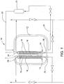
- FIG. 1 A simplified system 10 according to the invention is shown schematically in FIG. 1 .
- a brine supply 20 is provided that is connected to the bath 12 via a brine supply line 22.
- a brine recirculation line 24 is also provided which draws spent brine out of the bath 12 and returns it to the brine supply 20.
- brine is circulated through the bath 12 and around and past the electrolytic cells 14. As the brine passes the electrolytic cells 14, it is subject to an electrolysis reaction with the negatively charged ions being drawn into the cell 14 with the positively charged electrode plate 16 and the positively charged ions being drawn in the cell with the negatively charged electrode plate 16.
- Each of the electrolytic cells 14 has a fresh water inlet end 26 that is connected to a supply of fresh water that is directed into the interior space in the cell 14 between the membranes 18 and the electrode plate 16.
- the fresh water mixes with the ions drawn into the cell to form either the acid sanitizer (in the cell 14 with the positively charged plate 16) or the base cleaner (in the cell 14 with the negatively charged plate 16).
- Each cell 14 has a chemical outlet end 28 that is connected to a line for drawing the chemicals (acid sanitizer or base cleaner) out of the cell 14.
- the flow of the brine, fresh water and finished chemicals through the system can be controlled by appropriate pumps.
- the electrolytic cells 14 can have a modular design with each cell comprising a separate self-contained cartridge that permits multiple cells to be assembled together. This permits the system to be scaled to the desired production rate simply by adding or subtracting additional cells or cartridges.
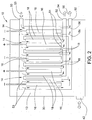
- FIGS. 2-4 An illustrative embodiment of a system including such modular cells 14 is shown in FIGS. 2-4 .
- the illustrated embodiment includes a total of five electrolytic cells 14 (three negatively charged and two positively charged) arranged in a manifold type arrangement in a brine bath 12.
- the cells 14 are generally rectangular in shape and are received in a rectangular housing 30 that defines the brine bath 12. As shown in FIG.
- the illustrated embodiment includes five cells 14, however, it will be understood that the more or less cells could be provided.
- a system with only three cells could be provided that had either a 2:1 acid sanitizer to base cleaner production rate or a 2:1 base to acid production rate.
- adjacent cells 14 would have one positively charged electrode plate 16 and one negatively charged electrode plate 16, so that during operation, the positively charged ions would flow through the membrane 18 of one cell 14 toward the negatively charged plate 16 and the negatively charged ions would flow through the membrane 18 of the adjacent cell 14 toward the positively charged plate 16. While the assembly of several cells 14 into a manifold type arrangement is shown, it will be appreciated that the cells could be independently submerged in the brine bath 12 as each of the individual cells is designed to be self-contained.
- the illustrated brine bath 12 includes a brine inlet/outlet 42 at the lower end of the bath housing 30 through which brine can be introduced into and drawn out of the bath 12.
- the bath housing 30 further includes a fresh water inlet 50, in this case, near the upper end of the housing that can be in communication with a fresh water supply. The inletting fresh water is shown by the arrow 53 in FIG. 2 .
- the fresh water introduced through the fresh water inlet 50 is directed into the individual electrolytic cells 14 wherein it mixes with the positively and negatively charged ions drawn through the membranes 18 to form the acid sanitizer and base cleaner.
- the bath housing 30 further includes outlets 52 for the formed chemicals arranged in the illustrated embodiment at the lower end of the bath housing.
- the outletting acid sanitizer is referenced with the arrow 56 and the outletting base cleaner is reference with the arrow 54 in FIG. 2 .
- the water/chemicals flow downward from the top of the cells 14 and exit at the bottom of the cells 14.
- the flow of water/chemicals through the interior of the cells 14 is shown diagrammatically with arrows in FIG. 2 with the flow of the water being shown with arrows 53, the flow of the base cleaner being shown with arrows 54 and the flow of the acid sanitizer being shown with arrows 56.
- each cell 14 includes an electrode plate 16 that is either positively or negatively charged.
- each electrode plate 16 has an attached lead 80 that can be connected to a suitable electrical supply.
- the electrode plates 16 can have a solid construction as discussed above, the electrodes 16 could also employ a honeycomb-like structure featuring a plurality of openings in the electrode as well as a non-flat, such as a dimpled, configuration. Such a construction can have the advantage that it disrupts and introduces turbulence into the flow of fresh water as it passes over the electrode 16. It is thought that this additional turbulence may help the efficiency of the system.
- the three cells 14 in the middle of the manifold each have an ion exchange membrane 18 on either side of the electrode 16.
- the two outmost cells 14 each have only one membrane 18 with a blank wall 81 being provided on the other side of the cell 14 to define the edge of the cell manifold.
- membrane supports 38 can be provided on the outer surface of each of the membranes 18. These membrane supports 38 enable each cell 14 to be arranged together with an immediately adjacent similarly constructed cell 14 to create the manifold type arrangement of two or more cells.
- the illustrated membrane supports 38 have a window-like configuration with six large openings through which the brine can access the membrane 18.
- cylindrical outer spacers 82 are arranged on an outer face of every other membrane support 38 in the manifold and engage the outer face of the membrane support 38 of the adjacent cell 14 so as to create space between the adjacent cells 14 into which the brine can permeate.
- each cell 14 further includes a cartridge housing 40 which provides a structure to which the electrode 16, membrane 18 and membrane supports 38 can be attached.
- the cartridge housings 40 have a generally window like configuration and are constructed in such a manner that when the membranes 18 and electrode 16 are connected thereto sufficient space is provided between the electrode 16 and the membrane 18 to permit the flow of freshwater through the cell 14 and into which ions can be drawn to produce the base cleaner and acid sanitizer.
- the interior space in the cells 14 between the membranes 18 and the electrode plates 16 into which the charged ions are drawn are sealed off from the brine bath 12 such that the only flow path from the bath 12 into the interior spaces is through the membranes.
- the illustrated configuration of the cartridge housings 40 limits the points of contact between the cartridge housings 40 and the electrode 16 and the cartridge housings 40 and the respective membrane 18 and thereby defines open spaces in the area between membranes 18 and the electrode plate 16.
- the membranes 18 are largely unobstructed by the cartridge housings 40 and the membrane supports 38 and the membranes 18 are not directly attached to the electrode plates 16 so as to allow maximum ion transfer from the brine bath 12 to the cell 14.
- the lack of obstructions to the membranes 18 also allows for fluid to be constantly refreshed at the membrane surfaces helping to further increase the efficiency of the system 10.
- other types of arrangements could be used to provide the spacing between the membranes and the surfaces of the electrode plates. For example, raised dimples could be provided on the electrode plate or polyurethane standoffs could be provided.
- each cell includes a fresh water distribution channel 62, in this case, through an upper edge of the cartridge housing 40.
- the fresh water distribution channel 62 communicates with the space between the electrode 16 and the membranes 18 (or membrane if only one is provided) via series of passages 84 that extend through the cartridge housing 40 from the distribution channel 62 and communicate with the area between the electrode 16 and the membranes 18.
- the openings for these passages 84 are best shown in FIG. 4 .
- Similar passages are provided at the other end of the cartridge housing 40 to allow the now formed acid sanitizer or base cleaner to pass into a chemical collection chamber 64 that extends through the lower edge of the cartridge housing 40.
- the fresh water distribution channels 62 for each cell 14 are in communication with the fresh water inlet 50 to the housing 30 as shown schematically in FIG. 2 .
- the chemical collection channels 64 for each cell 14 are in communication with the appropriate chemical outlet 52 as also shown schematically in FIG. 2 .
- each cell 14 has its own fresh water distribution channel 62 and chemical collection chamber 64, each cell can be considered to be self-contained in that it simply needs to be immersed in the brine bath and connected to a fresh water source and to a finished chemical outlet.
- the cells 14 and system 10 could be configured such that the water is introduced and the chemicals drawn off from the same end of the cells.
- the cells 14 and system 10 could be designed such that the water is introduced on one side of the electrode 16 and then travels down one side of the electrode.
- the water/chemicals is transferred to the other side of the electrode 16 where it travels up the opposite side of the electrode.
- the chemicals are then drawn off at the same end of the cell 14 at which the water was first introduced, but on the opposite side of the electrode 16.
- the electrodes and the membranes can be approximately 20 mm thick and the membranes can be approximately .018 inches thick and be able to withstand an 80 psi pressure differential across the membrane.
- the precise distances between the membranes and electrodes of a given cell and the electrodes of adjacent cells can be optimized through the sizing of the cartridge housings and the membrane supports to reduce energy loss from resistive losses in the fluids.
- the water flow through the inner spaces between the membranes 18 and electrode plates 16 can be regulated with an appropriate control system.
- the control system can be used to regulate the water flow and the electrical current so as to control the formation of the acid sanitizer and base cleaner at the desired production rate and at the desired pH.
- the same or a different control system can be used to control the supply of brine in the bath, including providing replenishment of the supply of brine in the bath during operation.
- the control system can include pumps for the water and brine, valves and suitable electronic controls.
- each cell 14 includes either a positive or negatively charged electrode plate 16 with membranes 18 arranged on both of the flat sides of the plate.
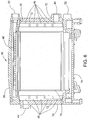
- the illustrated housing 30 includes four side walls 32 and attaches to a lower base 34 and an upper cap or cover 36.
- the electrolytic cells 14 are arranged in an upright manner in the bath 12 and extend between the base 34 and the cover 36 and electrical connections 37 (see FIGS. 5 and 7 ) for the electrode plates 16 are provided in the base 34.
- the cells 14 are supported in the housing 30 in parallel closely spaced relation to each other in a manifold type arrangement.
- the illustrated embodiment includes four cells 14.
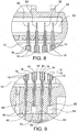
- Membrane supports 38 are provided on the outer surface of each of the membranes 18 as best shown in FIGS. 7 and 10 .
- a single membrane support 38 can be provided between adjacent cells 14 in order to provide support for the membranes 18 of the adjacent cells 14 as shown in FIG. 10 .
- the membrane supports 38 can provide a window pane-like configuration with legs extending around the perimeter of the respective membrane 18 and cross-members that extend between two of the legs so as to define open spaces between the membranes 18 of adjacent cells (see, e.g., FIGS. 11 and 12 ).
- First cartridge housings 40 can also be provided on either side of each electrode plate 16.
- the membrane 18 can be attached to each of the cartridge housings 40 so that the membrane 18 is spaced a distance from the corresponding surface of the electrode plate 16 thereby defining an interior space in the cell 14. This spacing is best shown in FIG. 10 .
- the cartridge housings 40 can provide a window pane-like configuration with legs extending around the perimeter of the electrode plate 16.
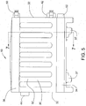
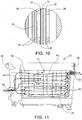
- fresh brine is fed to the bath 12 in the interior of the housing 30 through an inlet 42 provided on one of the sidewalls 32 of the housing (see FIGS. 5 and 6 ).
- the brine flows past the outer surface of the membranes 18 of a cell 14 on either side of the respective electrode plate 16 to a brine outlet 44 provided, in the illustrated embodiment, on the opposing sidewall 32 of the housing.
- the flow of brine between the inlet and outlet 42, 44 is shown diagrammatically with arrows 45 in FIG. 11 .
- the membrane supports 38 each have a plurality of brine flow entry 46 and exit passages 48 (see FIG.
- the interior of the cells 14 between the membranes 18 and the electrode plate 16 are in fluid communication with a source of water that mixes with the ions drawn through the membranes to form the acid sanitizer and base cleaner.
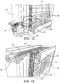
- the housing 30 includes a fresh water inlet 50, in this case at the upper end of one of the sidewalls 32 of the housing (see FIGS. 5 , 6 and 13 ).
- Outlets 52 for the formed chemicals are arranged, in this case, at the lower end of one of the sidewalls 32 of the housing 30 (see FIGS. 5 , 6 and 14 ).
- the water/chemicals flow downward from the top of the cells 14 and exit at the bottom of the cells 14.
- FIGS. 13 and 14 The flow of water/chemicals through the interior of the cells is shown diagrammatically with arrows in FIGS. 13 and 14 with the flow of the water being shown with arrows 53, the flow of the base cleaner being shown with arrows 54 and the flow of the acid sanitizer being shown with arrows 56 in FIG. 14 .
- the cells 14 include a plurality of entry passages 58 along the upper edge thereof and exit passages 60 along the lower end thereof as shown, for example, in FIG. 6 .
- the entry and exit passages 58, 60 are defined by slots in the electrode plate (see, e.g., FIG. 13 ).
- the entry passages 58 along the upper end of the cells 14 connect to a fresh water distribution chamber 62 that is in communication with the fresh water inlet 50 as shown in FIGS. 8 and 13 .
- the exit passages 60 along the opposing lower edge of the cells 14 connect to chemical collection areas 64 that are in communication with the respective chemical outlets 52 through which the acid sanitizer or base cleaner formed in the cell 14 can be drawn out of the system 10 (see FIGS. 9 and 14 ) via distribution channels provided in the base 34 of the housing 10.
- Separate collection areas 64 and distribution channels are provided for the cells 14 with positively charged electrode plates 16 and those with negatively charged electrode plates 16 to keep the formed acid sanitizer and base cleaner separated as best shown in FIG. 9 .
- the fresh water distribution chamber 62 in the cover plate of the housing and the chemical collection areas 64 in the base of the housing should be sealed off from the brine bath to prevent any contamination from the brine.
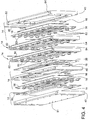
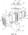
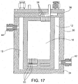
- FIGS. 15-20 A further embodiment of an electrolyzing system 10 is shown in FIGS. 15-20 .
- This embodiment has similarities to the other disclosed embodiments and for ease of reference like components have been given the same reference numbers in the figures.
- the main difference between this embodiment and the embodiment of FIGS. 5-14 lies in the way the water/chemicals flow through the system 10 and the resultant location of the various inlets and outlets.
- the fresh water inlet 50 and the chemical outlets 52 are both arranged in the top of the housing 30. Because of this arrangement, the water/chemical flow first travels down one cell 14, then is directed across to another like charged cell 14 and then up that cell where it then exits the system.
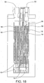
- FIG. 19 diagrammatically shows with arrows both the brine flow (arrows 66), fresh water flow (arrows 67) and chemical flow (arrows 68) through the system.
- the brine flow past the outer surfaces of the membranes 18 of the individual cells 14 is generally the same as that described in connection with the previously described embodiments.
- the flow of the water/chemical is shown in greater detail in FIG. 20 with respect to the flow associated with the positively charged electrolytic cells 14.
- fresh water is shown entering a positively charged electrolytic cell 14 through the upper end thereof into the interior space between the electrode plate 16 and the associated membranes 18. It then travels downward through the cell 14 until it reaches the bottom.
- the top plate of the housing includes separate distribution channels 72, 74 for the two chemical products (i.e., separate distribution channels for the outlet of the positively charged cells and for the outlet of the negatively charged cells) to direct the products to their respective outlets 52.
Landscapes
- Chemical & Material Sciences (AREA)
- Engineering & Computer Science (AREA)
- Chemical Kinetics & Catalysis (AREA)
- Electrochemistry (AREA)
- Organic Chemistry (AREA)
- Water Supply & Treatment (AREA)
- Hydrology & Water Resources (AREA)
- Environmental & Geological Engineering (AREA)
- Life Sciences & Earth Sciences (AREA)
- General Chemical & Material Sciences (AREA)
- Materials Engineering (AREA)
- Metallurgy (AREA)
- Inorganic Chemistry (AREA)
- Water Treatment By Electricity Or Magnetism (AREA)
- Electrolytic Production Of Non-Metals, Compounds, Apparatuses Therefor (AREA)
- Separation Using Semi-Permeable Membranes (AREA)
Claims (10)
- Un système d'électrolyse (10) destiné à l'électrolyse d'une solution aqueuse de saumure et d'un sel alcalin de façon à produire une eau électrolysée acide et une eau électrolysée alcaline, le système comprenant :un logement (30) comprenant une chambre interne destinée à la réception de la solution de saumure et à la définition d'un bain de saumure (12),une première cellule d'électrolyseur (14) agencée dans la chambre interne du logement (30), la première cellule d'électrolyseur (14) étant immergée dans ledit bain de saumure (12), ladite première cellule d'électrolyseur (14) comprenant une première plaque d'électrode (16) qui est électriquement chargée avec une charge positive,une deuxième cellule d'électrolyseur (14) agencée dans la chambre interne dans le logement (30), la deuxième cellule d'électrolyseur (14) étant immergée dans ledit bain de saumure (12), ladite deuxième cellule d'électrolyseur (14) comprenant une deuxième plaque d'électrode (16) qui est électriquement chargée avec une charge négative, caractérisé en ce que :ladite première cellule d'électrolyseur (14) possède une paire de membranes perméables d'échange d'ions négatifs (18) disposées sur des côtés opposés de la première plaque d'électrode (16) de façon à définir un premier espace entre la première plaque d'électrode et la paire de membranes perméables d'échange d'ions négatifs (18) à l'intérieur de laquelle la première plaque d'électrode (16) est installée et dans laquelle des ions négatifs provenant de la solution de saumure peuvent entrer au travers des membranes perméables d'échange d'ions négatifs (18), ledit premier espace étant en communication avec une alimentation en eau douce au niveau d'une extrémité d'admission (26, 50) du premier espace et en communication avec une sortie de produit chimique de nettoyage au niveau d'une extrémité de sortie (28, 52) du premier espace, ledit premier espace étant scellé hermétiquement du bain de saumure (12) de sorte que le seul trajet permettant à la solution de saumure de pénétrer dans le premier espace soit au travers de la paire de membranes perméables d'échange d'ions négatifs (18) de sorte qu'un produit chimique de nettoyage sortant de la sortie de produit chimique de nettoyage (28, 52) du premier espace soit adapté à une utilisation en tant qu'assainissant acide, etladite deuxième cellule d'électrolyseur (14) possède une paire de membranes perméables d'échange d'ions positifs (18) disposée sur des côtés opposés de la deuxième plaque d'électrode (16) de façon à définir un deuxième espace entre la deuxième plaque d'électrode et la paire de membranes perméables d'échange d'ions positifs à l'intérieur de laquelle la deuxième plaque d'électrode (16) est installée et dans laquelle des ions positifs provenant de la solution de saumure peuvent entrer au travers des membranes perméables d'échange d'ions positifs (18), ledit deuxième espace étant en communication avec une alimentation en eau douce au niveau d'une extrémité d'admission (26, 50) du deuxième espace et en communication avec une sortie de produit chimique de nettoyage au niveau d'une extrémité de sortie (28, 52) du deuxième espace, le deuxième espace étant scellé hermétiquement du bain de saumure de sorte que le seul trajet permettant à la solution de saumure de pénétrer dans le deuxième espace soit au travers de la paire de membranes perméables d'échange d'ions positifs (18) de sorte qu'un produit chimique de nettoyage sortant de la sortie de produit chimique de nettoyage du deuxième espace soit une eau électrolysée alcaline adaptée à une utilisation en tant que nettoyant basique.
- Le système d'électrolyse selon la Revendication 1, où lesdites membranes (18) sont chacune soutenues par un support de membrane respectif (38) agencé sur un côté des plaques d'électrode (16).
- Le système d'électrolyse selon la Revendication 1, où chacune des première et deuxième cellules d'électrolyseur (14) comprend un logement de cartouche (40) sur lequel les membranes respectives (18) et la plaque d'électrode (16) sont soutenues.
- Le système d'électrolyse selon la Revendication 1 où les première et deuxième cellules d'électrolyseur (14) sont agencées selon une relation parallèle espacée l'une par rapport à l'autre dans le bain de saumure (12) de façon à définir une zone entre elles dans laquelle la saumure peut s'écouler.
- Le système d'électrolyse selon la Revendication 1 comprenant une pluralité desdites première et deuxième cellules d'électrolyse (14), et ladite pluralité de cellules d'électrolyse (14) étant agencée dans le bain de saumure (12) de sorte que les plaques d'électrode respectives (16) de cellules adjacentes (14) soient à charges opposées.
- Le système d'électrolyse selon la Revendication 1 dans lequel ladite plaque d'électrode (16) et lesdites membranes (18) de ladite première cellule d'électrolyseur (14) font partie d'une première cartouche de cellule d'électrolyseur (40), ladite plaque d'électrode (16) et lesdites membranes (18) de ladite deuxième cellule d'électrolyseur (14) font partie d'une deuxième cartouche de cellule d'électrolyseur (40), et lesdites cartouches (40) étant chacune assemblables individuellement dans ledit logement (30).
- Un procédé d'électrolyse d'une solution aqueuse de saumure et d'un sel alcalin exécuté dans l'appareil selon la Revendication 1 de façon à produire une eau électrolysée acide et une eau électrolysée alcaline, le procédé comprenant :la fourniture d'une solution de saumure dans un bain de saumure (12) défini par une chambre interne d'un logement (30),l'immersion d'une première cellule d'électrolyseur (14) dans le bain de saumure (12) possédant une première plaque d'électrode (16) et une paire de membranes perméables d'échange d'ions négatifs (18) définissant un premier espace à l'intérieur duquel la première plaque d'électrode (16) est installée qui est scellé hermétiquement du bain de saumure (12) de sorte que le seul trajet permettant à la solution de saumure de pénétrer dans le premier espace soit au travers des membranes perméables d'échange d'ions négatifs (18),la charge électrique de la première plaque d'électrode (16) avec une charge positive,la fourniture d'eau douce à une extrémité d'admission (26, 50) du premier espace entre les membranes perméables d'échange d'ions négatifs (18),l'extraction d'une eau électrolysée acide à partir d'une extrémité de sortie (28, 52) du premier espace adaptée à une utilisation en tant qu'assainissant acide,l'immersion d'une deuxième cellule d'électrolyseur (14) dans le bain de saumure (12) possédant une deuxième plaque d'électrode (16) et une paire de membranes perméables d'échange d'ions positifs (18) définissant un deuxième espace à l'intérieur duquel la deuxième plaque d'électrode (16) est installée qui est scellée hermétiquement du bain de saumure (12) de sorte que le seul trajet permettant à la solution de saumure de pénétrer dans le deuxième espace soit au travers des membranes perméables d'échange d'ions positifs (18),la charge électrique de la deuxième plaque d'électrode (16) avec une charge négative,la fourniture d'eau douce à une extrémité d'admission (26, 50) du deuxième espace entre les membranes perméables d'échange d'ions positifs (18), etl'extraction d'une eau électrolysée alcaline adaptée à une utilisation en tant que nettoyant basique à partir d'une extrémité de sortie (28, 52) du deuxième espace.
- Le procédé selon la Revendication 7 comprenant en outre l'opération d'insertion dans et de retrait sélectif du bain de saumure (12) d'une ou de plusieurs des cellules d'électrolyseur (14) du bain de saumure de façon à fournir un taux de production souhaité d'eau électrolysée acide et d'eau électrolysée alcaline.
- Le procédé selon la Revendication 7 comprenant l'agencement des cellules d'électrolyseur (14) dans le bain de saumure (12) avec les plaques d'électrode respectives (16) de cellules adjacentes qui sont à charges opposées.
- Le procédé selon la Revendication 7 comprenant l'agencement des cellules d'électrolyseur (14) en relation parallèle espacée dans le bain de saumure (12) de façon à définir une zone entre des cellules adjacentes (12) dans laquelle la saumure peut s'écouler.
Applications Claiming Priority (2)
| Application Number | Priority Date | Filing Date | Title |
|---|---|---|---|
| US32686910P | 2010-04-22 | 2010-04-22 | |
| PCT/US2011/033528 WO2011133835A1 (fr) | 2010-04-22 | 2011-04-22 | Système d'électrolyse |
Publications (3)
| Publication Number | Publication Date |
|---|---|
| EP2561121A1 EP2561121A1 (fr) | 2013-02-27 |
| EP2561121A4 EP2561121A4 (fr) | 2014-10-22 |
| EP2561121B1 true EP2561121B1 (fr) | 2016-06-01 |
Family
ID=44814869
Family Applications (1)
| Application Number | Title | Priority Date | Filing Date |
|---|---|---|---|
| EP11772747.9A Active EP2561121B1 (fr) | 2010-04-22 | 2011-04-22 | Système d'électrolyse |
Country Status (18)
| Country | Link |
|---|---|
| US (2) | US8753489B2 (fr) |
| EP (1) | EP2561121B1 (fr) |
| JP (1) | JP5761874B2 (fr) |
| KR (1) | KR101861864B1 (fr) |
| CN (1) | CN102947490B (fr) |
| AU (1) | AU2011242614B2 (fr) |
| BR (1) | BR112012027028B1 (fr) |
| CA (1) | CA2796904C (fr) |
| CL (1) | CL2012002941A1 (fr) |
| CO (1) | CO6640233A2 (fr) |
| ES (1) | ES2584652T3 (fr) |
| HK (1) | HK1177479A1 (fr) |
| MX (1) | MX343210B (fr) |
| NZ (1) | NZ603195A (fr) |
| PL (1) | PL2561121T3 (fr) |
| SG (2) | SG10201503169SA (fr) |
| WO (1) | WO2011133835A1 (fr) |
| ZA (1) | ZA201208339B (fr) |
Families Citing this family (17)
| Publication number | Priority date | Publication date | Assignee | Title |
|---|---|---|---|---|
| WO2011133835A1 (fr) | 2010-04-22 | 2011-10-27 | Spraying Systems Co. | Système d'électrolyse |
| US8486236B1 (en) * | 2010-06-17 | 2013-07-16 | Walter B. Warning | Electrolysis chamber |
| WO2014062837A1 (fr) * | 2012-10-16 | 2014-04-24 | GenEon Technologies LLC | Activation électrochimique de l'eau |
| DE102014203374B4 (de) | 2014-02-25 | 2018-05-03 | Condias Gmbh | Elektrodenanordnung und Verfahren zum elektrochemischen Herstellen von elektrolysiertem Wasser |
| WO2016043072A1 (fr) * | 2014-09-19 | 2016-03-24 | 株式会社 東芝 | Dispositif électrolytique, unité d'électrode, et procédé de production d'eau électrolytique |
| MX2017009999A (es) * | 2015-02-04 | 2017-10-19 | Spraying Systems Co | Cartucho electrolitico, sistemas y metodos para su uso. |
| AU2016277127B2 (en) | 2015-06-12 | 2021-04-01 | Spraying Systems Co. | High volume water electrolyzing system and method of using |
| US20170029261A1 (en) * | 2015-07-31 | 2017-02-02 | Spraying Systems Co. | System for filling liquid containing bottles |
| JP6578181B2 (ja) * | 2015-10-08 | 2019-09-18 | モレックス エルエルシー | 電解水の製造装置 |
| KR20180123022A (ko) * | 2016-03-11 | 2018-11-14 | 스프레잉 시스템즈 컴파니 | 휴대용 전기 분해 시스템 |
| WO2017186980A1 (fr) * | 2016-04-29 | 2017-11-02 | Cuevas Cuadrado Antonio | Réacteur électrolytique pour la production d'eau désinfectée et de désinfectant |
| CN106757132A (zh) * | 2017-01-12 | 2017-05-31 | 精迪敏健康医疗科技有限公司 | 电解设备 |
| US11084739B2 (en) * | 2017-03-01 | 2021-08-10 | Axine Water Technologies Inc. | Stack of electrochemical cells for wastewater treatment with isolated electrodes |
| AU2018256429B2 (en) * | 2017-04-20 | 2023-04-27 | Axine Water Technologies Inc. | Electrochemical cell for wastewater treatment with improved electrical protection |
| US11339483B1 (en) | 2021-04-05 | 2022-05-24 | Alchemr, Inc. | Water electrolyzers employing anion exchange membranes |
| KR102647107B1 (ko) | 2021-09-15 | 2024-03-19 | (주) 테크윈 | 카트리지 형식 전해셀, 이를 이용한 전해조 |
| KR20230106263A (ko) | 2022-01-06 | 2023-07-13 | (주) 테크윈 | 중력식 전해조를 구비하는 연속운전식 전해 시스템 및 그 중력식 전해조 |
Family Cites Families (25)
| Publication number | Priority date | Publication date | Assignee | Title |
|---|---|---|---|---|
| DE2607906A1 (de) * | 1976-02-26 | 1977-09-01 | Hans Einhell Inh Josef Thannhu | Elektrolysezelle fuer die behandlung von wasser |
| GB1595183A (en) * | 1977-03-04 | 1981-08-12 | Ici Ltd | Diaphragm cell |
| IT1248564B (it) * | 1991-06-27 | 1995-01-19 | Permelec Spa Nora | Processo di decomposizione elettrochimica di sali neutri senza co-produzione di alogeni o di acido e cella di elettrolisi adatta per la sua realizzazione. |
| IT1263899B (it) * | 1993-02-12 | 1996-09-05 | Permelec Spa Nora | Migliorato processo di elettrolisi cloro-soda a diaframma e relativa cella |
| JP2857334B2 (ja) | 1994-10-18 | 1999-02-17 | 行正 佐藤 | 電解イオン水生成装置 |
| EP0723936B1 (fr) | 1995-01-30 | 1999-05-12 | First Ocean Co., Ltd. | Construction d'une électrode composite pour l'électrolyse de l'eau |
| WO1996029133A1 (fr) | 1995-03-23 | 1996-09-26 | Ionics, Incorporated | Ameliorations des traitements par membrane notamment l'electrodialyse |
| JPH1043764A (ja) | 1996-08-06 | 1998-02-17 | First Ocean Kk | 水電気分解用電極及びそれを用いて水を滅菌する方法 |
| JP3570279B2 (ja) * | 1999-03-17 | 2004-09-29 | 栗田工業株式会社 | 電気脱塩装置 |
| JP2001259643A (ja) * | 2000-03-16 | 2001-09-25 | Matsushita Electric Ind Co Ltd | 脱イオン水製造装置とアルカリ性水製造装置と酸性水製造装置 |
| US6638364B2 (en) | 2000-09-08 | 2003-10-28 | Electric Aquagenics Unlimited | System to clean and disinfect carpets, fabrics, and hard surfaces using electrolyzed alkaline water produced from a solution of NaCl |
| WO2003048421A1 (fr) * | 2001-12-05 | 2003-06-12 | Micromed Laboratories, Inc. | Procede et dispositif de production d'eau aux potentiels d'oxydo-reduction negatifs et positifs |
| WO2003076688A2 (fr) * | 2002-03-06 | 2003-09-18 | The University Of Georgia Research Foundation, Inc. | Procede et appareil d'electrolyse de l'eau |
| JP2003311270A (ja) | 2002-04-18 | 2003-11-05 | First Ocean Kk | 液体分配器 |
| JP4116328B2 (ja) | 2002-05-27 | 2008-07-09 | 本田技研工業株式会社 | 膜電極構造体及びその製造方法 |
| JP2004058006A (ja) | 2002-07-31 | 2004-02-26 | First Ocean Kk | 電解水製造方法 |
| US20050161343A1 (en) * | 2004-01-22 | 2005-07-28 | Reinhard Fred P. | Apparatus and method for brine separation and reuse |
| CN2711145Y (zh) * | 2004-04-08 | 2005-07-20 | 叶清源 | 电解水装置的一种电解槽 |
| US8858765B2 (en) | 2005-05-20 | 2014-10-14 | Ecolab Usa Inc. | Acidic electrolyzed water production system and generation control method |
| JP2007049951A (ja) * | 2005-08-19 | 2007-03-01 | Masayoshi Iwahara | 海藻抽出液の濃縮方法 |
| JP2009072778A (ja) | 2007-04-13 | 2009-04-09 | Masaaki Arai | 電解水の製造装置、電解水の製造方法および電解水 |
| JP3139159U (ja) | 2007-11-20 | 2008-01-31 | ファースト・オーシャン株式会社 | 水電気分解用電解槽 |
| US20110042230A1 (en) | 2009-01-28 | 2011-02-24 | Gilliam Ryan J | Low-energy electrochemical bicarbonate ion solution |
| US20120012466A1 (en) * | 2010-01-07 | 2012-01-19 | Sealed Air Corporation | Modular Cartridge System for Apparatus Producing Cleaning and/or Sanitizing Solutions |
| WO2011133835A1 (fr) | 2010-04-22 | 2011-10-27 | Spraying Systems Co. | Système d'électrolyse |
-
2011
- 2011-04-22 WO PCT/US2011/033528 patent/WO2011133835A1/fr active Application Filing
- 2011-04-22 BR BR112012027028A patent/BR112012027028B1/pt active IP Right Grant
- 2011-04-22 NZ NZ603195A patent/NZ603195A/en unknown
- 2011-04-22 JP JP2013506318A patent/JP5761874B2/ja active Active
- 2011-04-22 SG SG10201503169SA patent/SG10201503169SA/en unknown
- 2011-04-22 SG SG2012078119A patent/SG184969A1/en unknown
- 2011-04-22 CN CN201180031385.2A patent/CN102947490B/zh active Active
- 2011-04-22 ES ES11772747.9T patent/ES2584652T3/es active Active
- 2011-04-22 KR KR1020127030037A patent/KR101861864B1/ko active IP Right Grant
- 2011-04-22 PL PL11772747T patent/PL2561121T3/pl unknown
- 2011-04-22 CA CA2796904A patent/CA2796904C/fr active Active
- 2011-04-22 MX MX2012012252A patent/MX343210B/es active IP Right Grant
- 2011-04-22 AU AU2011242614A patent/AU2011242614B2/en active Active
- 2011-04-22 EP EP11772747.9A patent/EP2561121B1/fr active Active
- 2011-04-22 US US13/092,278 patent/US8753489B2/en active Active
-
2012
- 2012-10-19 CL CL2012002941A patent/CL2012002941A1/es unknown
- 2012-11-06 ZA ZA2012/08339A patent/ZA201208339B/en unknown
- 2012-11-21 CO CO12210659A patent/CO6640233A2/es active IP Right Grant
-
2013
- 2013-04-16 HK HK13104565.2A patent/HK1177479A1/zh unknown
-
2014
- 2014-03-26 US US14/225,532 patent/US9103043B2/en active Active
Also Published As
| Publication number | Publication date |
|---|---|
| CA2796904C (fr) | 2018-12-18 |
| US9103043B2 (en) | 2015-08-11 |
| KR101861864B1 (ko) | 2018-06-29 |
| HK1177479A1 (zh) | 2013-08-23 |
| JP2013525607A (ja) | 2013-06-20 |
| EP2561121A1 (fr) | 2013-02-27 |
| US20110259760A1 (en) | 2011-10-27 |
| WO2011133835A1 (fr) | 2011-10-27 |
| KR20130062933A (ko) | 2013-06-13 |
| CN102947490A (zh) | 2013-02-27 |
| PL2561121T3 (pl) | 2017-09-29 |
| US8753489B2 (en) | 2014-06-17 |
| BR112012027028A2 (pt) | 2016-07-19 |
| JP5761874B2 (ja) | 2015-08-12 |
| CL2012002941A1 (es) | 2013-04-12 |
| CN102947490B (zh) | 2016-04-13 |
| US20140202872A1 (en) | 2014-07-24 |
| MX2012012252A (es) | 2012-12-17 |
| EP2561121A4 (fr) | 2014-10-22 |
| CO6640233A2 (es) | 2013-03-22 |
| AU2011242614B2 (en) | 2014-07-24 |
| BR112012027028B1 (pt) | 2019-12-24 |
| ZA201208339B (en) | 2013-07-31 |
| SG10201503169SA (en) | 2015-08-28 |
| NZ603195A (en) | 2014-03-28 |
| SG184969A1 (en) | 2012-11-29 |
| CA2796904A1 (fr) | 2011-10-27 |
| MX343210B (es) | 2016-10-27 |
| ES2584652T3 (es) | 2016-09-28 |
Similar Documents
| Publication | Publication Date | Title |
|---|---|---|
| EP2561121B1 (fr) | Système d'électrolyse | |
| AU2011242614A1 (en) | Electrolyzing system | |
| CN107921372B (zh) | 大容量水电解系统及其使用方法 | |
| TWI622666B (zh) | 電解水生成裝置 | |
| EP3253716B1 (fr) | Système de cartouches électrolytiques | |
| KR101779032B1 (ko) | 수전해조 및 이를 이용하는 미용기구 | |
| CN220034146U (zh) | 一种电解槽 | |
| KR102062810B1 (ko) | 냉각식 통형 유격막 전해수 생성장치 | |
| JPH03271385A (ja) | 水電解用複極式電解槽 | |
| CN116874039A (zh) | 一种电解槽 | |
| JPH06200393A (ja) | 次亜塩素酸塩製造用電解槽 | |
| CN116874037A (zh) | 一种电解槽 | |
| CN116874036A (zh) | 一种电解槽 | |
| NZ738258B2 (en) | High volume water electrolyzing system and method of using |
Legal Events
| Date | Code | Title | Description |
|---|---|---|---|
| PUAI | Public reference made under article 153(3) epc to a published international application that has entered the european phase |
Free format text: ORIGINAL CODE: 0009012 |
|
| 17P | Request for examination filed |
Effective date: 20121018 |
|
| AK | Designated contracting states |
Kind code of ref document: A1 Designated state(s): AL AT BE BG CH CY CZ DE DK EE ES FI FR GB GR HR HU IE IS IT LI LT LU LV MC MK MT NL NO PL PT RO RS SE SI SK SM TR |
|
| DAX | Request for extension of the european patent (deleted) | ||
| REG | Reference to a national code |
Ref country code: HK Ref legal event code: DE Ref document number: 1177479 Country of ref document: HK |
|
| A4 | Supplementary search report drawn up and despatched |
Effective date: 20140923 |
|
| RIC1 | Information provided on ipc code assigned before grant |
Ipc: C25B 9/18 20060101ALN20140917BHEP Ipc: C02F 1/46 20060101ALI20140917BHEP Ipc: C02F 1/461 20060101ALN20140917BHEP Ipc: C25B 1/46 20060101ALI20140917BHEP Ipc: C25B 1/00 20060101AFI20140917BHEP Ipc: C25B 1/16 20060101ALI20140917BHEP Ipc: C02F 1/467 20060101ALN20140917BHEP |
|
| 17Q | First examination report despatched |
Effective date: 20151202 |
|
| GRAP | Despatch of communication of intention to grant a patent |
Free format text: ORIGINAL CODE: EPIDOSNIGR1 |
|
| INTG | Intention to grant announced |
Effective date: 20160225 |
|
| RIC1 | Information provided on ipc code assigned before grant |
Ipc: C25B 1/46 20060101ALI20160216BHEP Ipc: C02F 1/467 20060101ALN20160216BHEP Ipc: C02F 1/46 20060101ALI20160216BHEP Ipc: C25B 1/00 20060101AFI20160216BHEP Ipc: C25B 1/16 20060101ALI20160216BHEP Ipc: C25B 9/18 20060101ALN20160216BHEP Ipc: C02F 1/461 20060101ALN20160216BHEP |
|
| GRAS | Grant fee paid |
Free format text: ORIGINAL CODE: EPIDOSNIGR3 |
|
| GRAA | (expected) grant |
Free format text: ORIGINAL CODE: 0009210 |
|
| AK | Designated contracting states |
Kind code of ref document: B1 Designated state(s): AL AT BE BG CH CY CZ DE DK EE ES FI FR GB GR HR HU IE IS IT LI LT LU LV MC MK MT NL NO PL PT RO RS SE SI SK SM TR |
|
| REG | Reference to a national code |
Ref country code: GB Ref legal event code: FG4D |
|
| REG | Reference to a national code |
Ref country code: CH Ref legal event code: EP Ref country code: AT Ref legal event code: REF Ref document number: 803937 Country of ref document: AT Kind code of ref document: T Effective date: 20160615 |
|
| REG | Reference to a national code |
Ref country code: IE Ref legal event code: FG4D |
|
| REG | Reference to a national code |
Ref country code: DE Ref legal event code: R096 Ref document number: 602011027124 Country of ref document: DE |
|
| REG | Reference to a national code |
Ref country code: DK Ref legal event code: T3 Effective date: 20160729 |
|
| REG | Reference to a national code |
Ref country code: SE Ref legal event code: TRGR |
|
| REG | Reference to a national code |
Ref country code: NL Ref legal event code: FP |
|
| REG | Reference to a national code |
Ref country code: EE Ref legal event code: FG4A Ref document number: E012216 Country of ref document: EE Effective date: 20160720 |
|
| REG | Reference to a national code |
Ref country code: NO Ref legal event code: T2 Effective date: 20160601 Ref country code: LT Ref legal event code: MG4D |
|
| REG | Reference to a national code |
Ref country code: ES Ref legal event code: FG2A Ref document number: 2584652 Country of ref document: ES Kind code of ref document: T3 Effective date: 20160928 |
|
| PG25 | Lapsed in a contracting state [announced via postgrant information from national office to epo] |
Ref country code: LT Free format text: LAPSE BECAUSE OF FAILURE TO SUBMIT A TRANSLATION OF THE DESCRIPTION OR TO PAY THE FEE WITHIN THE PRESCRIBED TIME-LIMIT Effective date: 20160601 |
|
| PG25 | Lapsed in a contracting state [announced via postgrant information from national office to epo] |
Ref country code: HR Free format text: LAPSE BECAUSE OF FAILURE TO SUBMIT A TRANSLATION OF THE DESCRIPTION OR TO PAY THE FEE WITHIN THE PRESCRIBED TIME-LIMIT Effective date: 20160601 Ref country code: RS Free format text: LAPSE BECAUSE OF FAILURE TO SUBMIT A TRANSLATION OF THE DESCRIPTION OR TO PAY THE FEE WITHIN THE PRESCRIBED TIME-LIMIT Effective date: 20160601 Ref country code: GR Free format text: LAPSE BECAUSE OF FAILURE TO SUBMIT A TRANSLATION OF THE DESCRIPTION OR TO PAY THE FEE WITHIN THE PRESCRIBED TIME-LIMIT Effective date: 20160902 Ref country code: LV Free format text: LAPSE BECAUSE OF FAILURE TO SUBMIT A TRANSLATION OF THE DESCRIPTION OR TO PAY THE FEE WITHIN THE PRESCRIBED TIME-LIMIT Effective date: 20160601 |
|
| PG25 | Lapsed in a contracting state [announced via postgrant information from national office to epo] |
Ref country code: SK Free format text: LAPSE BECAUSE OF FAILURE TO SUBMIT A TRANSLATION OF THE DESCRIPTION OR TO PAY THE FEE WITHIN THE PRESCRIBED TIME-LIMIT Effective date: 20160601 Ref country code: IS Free format text: LAPSE BECAUSE OF FAILURE TO SUBMIT A TRANSLATION OF THE DESCRIPTION OR TO PAY THE FEE WITHIN THE PRESCRIBED TIME-LIMIT Effective date: 20161001 Ref country code: RO Free format text: LAPSE BECAUSE OF FAILURE TO SUBMIT A TRANSLATION OF THE DESCRIPTION OR TO PAY THE FEE WITHIN THE PRESCRIBED TIME-LIMIT Effective date: 20160601 Ref country code: CZ Free format text: LAPSE BECAUSE OF FAILURE TO SUBMIT A TRANSLATION OF THE DESCRIPTION OR TO PAY THE FEE WITHIN THE PRESCRIBED TIME-LIMIT Effective date: 20160601 |
|
| PG25 | Lapsed in a contracting state [announced via postgrant information from national office to epo] |
Ref country code: SM Free format text: LAPSE BECAUSE OF FAILURE TO SUBMIT A TRANSLATION OF THE DESCRIPTION OR TO PAY THE FEE WITHIN THE PRESCRIBED TIME-LIMIT Effective date: 20160601 Ref country code: PT Free format text: LAPSE BECAUSE OF FAILURE TO SUBMIT A TRANSLATION OF THE DESCRIPTION OR TO PAY THE FEE WITHIN THE PRESCRIBED TIME-LIMIT Effective date: 20161003 |
|
| REG | Reference to a national code |
Ref country code: DE Ref legal event code: R097 Ref document number: 602011027124 Country of ref document: DE |
|
| REG | Reference to a national code |
Ref country code: HK Ref legal event code: GR Ref document number: 1177479 Country of ref document: HK |
|
| REG | Reference to a national code |
Ref country code: FR Ref legal event code: PLFP Year of fee payment: 7 |
|
| PLBE | No opposition filed within time limit |
Free format text: ORIGINAL CODE: 0009261 |
|
| STAA | Information on the status of an ep patent application or granted ep patent |
Free format text: STATUS: NO OPPOSITION FILED WITHIN TIME LIMIT |
|
| 26N | No opposition filed |
Effective date: 20170302 |
|
| PG25 | Lapsed in a contracting state [announced via postgrant information from national office to epo] |
Ref country code: SI Free format text: LAPSE BECAUSE OF FAILURE TO SUBMIT A TRANSLATION OF THE DESCRIPTION OR TO PAY THE FEE WITHIN THE PRESCRIBED TIME-LIMIT Effective date: 20160601 |
|
| REG | Reference to a national code |
Ref country code: CH Ref legal event code: PL |
|
| PG25 | Lapsed in a contracting state [announced via postgrant information from national office to epo] |
Ref country code: MC Free format text: LAPSE BECAUSE OF FAILURE TO SUBMIT A TRANSLATION OF THE DESCRIPTION OR TO PAY THE FEE WITHIN THE PRESCRIBED TIME-LIMIT Effective date: 20160601 |
|
| PG25 | Lapsed in a contracting state [announced via postgrant information from national office to epo] |
Ref country code: CH Free format text: LAPSE BECAUSE OF NON-PAYMENT OF DUE FEES Effective date: 20170430 Ref country code: LI Free format text: LAPSE BECAUSE OF NON-PAYMENT OF DUE FEES Effective date: 20170430 Ref country code: LU Free format text: LAPSE BECAUSE OF NON-PAYMENT OF DUE FEES Effective date: 20170422 |
|
| REG | Reference to a national code |
Ref country code: FR Ref legal event code: PLFP Year of fee payment: 8 |
|
| PG25 | Lapsed in a contracting state [announced via postgrant information from national office to epo] |
Ref country code: MT Free format text: LAPSE BECAUSE OF NON-PAYMENT OF DUE FEES Effective date: 20170422 |
|
| PG25 | Lapsed in a contracting state [announced via postgrant information from national office to epo] |
Ref country code: AL Free format text: LAPSE BECAUSE OF FAILURE TO SUBMIT A TRANSLATION OF THE DESCRIPTION OR TO PAY THE FEE WITHIN THE PRESCRIBED TIME-LIMIT Effective date: 20160601 |
|
| PG25 | Lapsed in a contracting state [announced via postgrant information from national office to epo] |
Ref country code: HU Free format text: LAPSE BECAUSE OF FAILURE TO SUBMIT A TRANSLATION OF THE DESCRIPTION OR TO PAY THE FEE WITHIN THE PRESCRIBED TIME-LIMIT; INVALID AB INITIO Effective date: 20110422 |
|
| REG | Reference to a national code |
Ref country code: AT Ref legal event code: UEP Ref document number: 803937 Country of ref document: AT Kind code of ref document: T Effective date: 20160601 |
|
| PG25 | Lapsed in a contracting state [announced via postgrant information from national office to epo] |
Ref country code: BG Free format text: LAPSE BECAUSE OF FAILURE TO SUBMIT A TRANSLATION OF THE DESCRIPTION OR TO PAY THE FEE WITHIN THE PRESCRIBED TIME-LIMIT Effective date: 20160601 |
|
| PG25 | Lapsed in a contracting state [announced via postgrant information from national office to epo] |
Ref country code: CY Free format text: LAPSE BECAUSE OF NON-PAYMENT OF DUE FEES Effective date: 20160601 |
|
| PG25 | Lapsed in a contracting state [announced via postgrant information from national office to epo] |
Ref country code: MK Free format text: LAPSE BECAUSE OF FAILURE TO SUBMIT A TRANSLATION OF THE DESCRIPTION OR TO PAY THE FEE WITHIN THE PRESCRIBED TIME-LIMIT Effective date: 20160601 |
|
| PG25 | Lapsed in a contracting state [announced via postgrant information from national office to epo] |
Ref country code: TR Free format text: LAPSE BECAUSE OF FAILURE TO SUBMIT A TRANSLATION OF THE DESCRIPTION OR TO PAY THE FEE WITHIN THE PRESCRIBED TIME-LIMIT Effective date: 20160601 |
|
| PGFP | Annual fee paid to national office [announced via postgrant information from national office to epo] |
Ref country code: FR Payment date: 20230309 Year of fee payment: 13 |
|
| PGFP | Annual fee paid to national office [announced via postgrant information from national office to epo] |
Ref country code: SE Payment date: 20230227 Year of fee payment: 13 Ref country code: PL Payment date: 20230303 Year of fee payment: 13 Ref country code: IT Payment date: 20230310 Year of fee payment: 13 Ref country code: BE Payment date: 20230315 Year of fee payment: 13 |
|
| PGFP | Annual fee paid to national office [announced via postgrant information from national office to epo] |
Ref country code: NO Payment date: 20230412 Year of fee payment: 13 Ref country code: ES Payment date: 20230512 Year of fee payment: 13 Ref country code: DK Payment date: 20230414 Year of fee payment: 13 Ref country code: DE Payment date: 20230228 Year of fee payment: 13 |
|
| PGFP | Annual fee paid to national office [announced via postgrant information from national office to epo] |
Ref country code: FI Payment date: 20230411 Year of fee payment: 13 Ref country code: AT Payment date: 20230327 Year of fee payment: 13 |
|
| PGFP | Annual fee paid to national office [announced via postgrant information from national office to epo] |
Ref country code: NL Payment date: 20240315 Year of fee payment: 14 Ref country code: IE Payment date: 20240223 Year of fee payment: 14 |
|
| PGFP | Annual fee paid to national office [announced via postgrant information from national office to epo] |
Ref country code: EE Payment date: 20240305 Year of fee payment: 14 Ref country code: GB Payment date: 20240229 Year of fee payment: 14 |