EP2559639B1 - Système de tri à bandes croisées - Google Patents
Système de tri à bandes croisées Download PDFInfo
- Publication number
- EP2559639B1 EP2559639B1 EP12179858.1A EP12179858A EP2559639B1 EP 2559639 B1 EP2559639 B1 EP 2559639B1 EP 12179858 A EP12179858 A EP 12179858A EP 2559639 B1 EP2559639 B1 EP 2559639B1
- Authority
- EP
- European Patent Office
- Prior art keywords
- item
- loading station
- conveying
- belt
- cross
- Prior art date
- Legal status (The legal status is an assumption and is not a legal conclusion. Google has not performed a legal analysis and makes no representation as to the accuracy of the status listed.)
- Active
Links
- 238000000034 method Methods 0.000 claims description 31
- 230000004044 response Effects 0.000 claims description 15
- 238000007599 discharging Methods 0.000 claims description 4
- 230000008901 benefit Effects 0.000 description 14
- 230000008859 change Effects 0.000 description 2
- 230000001154 acute effect Effects 0.000 description 1
- 230000006872 improvement Effects 0.000 description 1
- 230000008569 process Effects 0.000 description 1
- 238000007430 reference method Methods 0.000 description 1
- 239000004753 textile Substances 0.000 description 1
Images


Classifications
-
- B—PERFORMING OPERATIONS; TRANSPORTING
- B65—CONVEYING; PACKING; STORING; HANDLING THIN OR FILAMENTARY MATERIAL
- B65G—TRANSPORT OR STORAGE DEVICES, e.g. CONVEYORS FOR LOADING OR TIPPING, SHOP CONVEYOR SYSTEMS OR PNEUMATIC TUBE CONVEYORS
- B65G47/00—Article or material-handling devices associated with conveyors; Methods employing such devices
- B65G47/52—Devices for transferring articles or materials between conveyors i.e. discharging or feeding devices
- B65G47/53—Devices for transferring articles or materials between conveyors i.e. discharging or feeding devices between conveyors which cross one another
-
- B—PERFORMING OPERATIONS; TRANSPORTING
- B65—CONVEYING; PACKING; STORING; HANDLING THIN OR FILAMENTARY MATERIAL
- B65G—TRANSPORT OR STORAGE DEVICES, e.g. CONVEYORS FOR LOADING OR TIPPING, SHOP CONVEYOR SYSTEMS OR PNEUMATIC TUBE CONVEYORS
- B65G17/00—Conveyors having an endless traction element, e.g. a chain, transmitting movement to a continuous or substantially-continuous load-carrying surface or to a series of individual load-carriers; Endless-chain conveyors in which the chains form the load-carrying surface
- B65G17/30—Details; Auxiliary devices
- B65G17/32—Individual load-carriers
- B65G17/34—Individual load-carriers having flat surfaces, e.g. platforms, grids, forks
- B65G17/345—Individual load-carriers having flat surfaces, e.g. platforms, grids, forks the surfaces being equipped with a conveyor
-
- B—PERFORMING OPERATIONS; TRANSPORTING
- B65—CONVEYING; PACKING; STORING; HANDLING THIN OR FILAMENTARY MATERIAL
- B65G—TRANSPORT OR STORAGE DEVICES, e.g. CONVEYORS FOR LOADING OR TIPPING, SHOP CONVEYOR SYSTEMS OR PNEUMATIC TUBE CONVEYORS
- B65G47/00—Article or material-handling devices associated with conveyors; Methods employing such devices
- B65G47/74—Feeding, transfer, or discharging devices of particular kinds or types
- B65G47/76—Fixed or adjustable ploughs or transverse scrapers
- B65G47/766—Adjustable ploughs or transverse scrapers
-
- B—PERFORMING OPERATIONS; TRANSPORTING
- B65—CONVEYING; PACKING; STORING; HANDLING THIN OR FILAMENTARY MATERIAL
- B65G—TRANSPORT OR STORAGE DEVICES, e.g. CONVEYORS FOR LOADING OR TIPPING, SHOP CONVEYOR SYSTEMS OR PNEUMATIC TUBE CONVEYORS
- B65G47/00—Article or material-handling devices associated with conveyors; Methods employing such devices
- B65G47/74—Feeding, transfer, or discharging devices of particular kinds or types
- B65G47/94—Devices for flexing or tilting travelling structures; Throw-off carriages
- B65G47/96—Devices for tilting links or platform
Definitions
- the invention relates to a sorting system comprising a plurality of linked carriages moveable in a sorting track and equipped with sideways or crosswise driveable cross-belts.
- EP0927689 discloses a system according to the preamble of claim 1 and a method for sorting of items by means of an equipment consisting of a plurality of conveyor platforms running along a route between an objects loading zone and an unloading zone, in which unloading zone the items are unloaded into collecting devices situated sideways with respect to the route of the conveyor platforms.
- Each of the conveyor platforms is fitted with means for unloading the conveyed items sideways with respect to the machine, i.e. a cross-belt sorting system.
- the method comprises that the items to be sorted are ordered in pairs so as to load them in the machine respecting the unloading order, two items are loaded on each conveyor platform so as to be positioned side by side on the conveyor platform. Unloading of the items is carried out according to the required order, when said conveyor platform runs near the collecting devices designed for the items.
- EP0927689 may limit an efficiency of that sorting system.
- the system for and manner of ordering the items may limit the efficiency of the system.
- the invention may be seen as an object of the present invention to provide an improved sorting system and an improved method of sorting items on the sorting system.
- the invention alleviates, mitigates or eliminates one or more of the above or other disadvantages singly or in any combination.
- a cross-belt sorting system for sorting items according to claim 1.
- an improved sorting system is provided.
- An improvement or advantage of the sorting system can be found to lie therein that the described system comprises a top-load loading station as described.
- the first and second sides or parts are relative to an imaginary border between side-by-side sides, parts or areas of the conveying surface.
- the imaginary border is in the conveying direction or substantially in the conveying direction.
- the two side by side items are preferably positioned so that a straight line transverse to the conveying direction and in the horizontal plane intercepts the two side by side items. It may be preferred that, e.g., a centre of each side by side item is positioned in the middle or substantially in the middle of a length of each conveying surface, where the length is measured in the moving direction.
- two side by side items may be positioned with their rearmost or their frontmost ends, when seen in the conveying direction as close to a rearmost and a frontmost end of a conveying surface, respectively.
- two such relatively small items may be so small that when they are, e.g., positioned on each of two sides of a single conveying surface, but one item towards the rearmost end of the conveying surface and the other item towards the frontmost end of the conveying surface, and although these items are positioned on each side of the imaginary border explained above, the straight line transverse to the conveying direction and in the horizontal plane do not intercept both items.
- first, second, third and even fourth sides or parts are hereby defined as first, second, third and fourth areas next to each other side by side.
- the number and size of a side, part or area is e.g. chosen in dependence of a distribution of item sizes.
- the top-load loading station is considered as such when the top-load loading station is positioned in a distance above the conveying surfaces so that a lowermost level of the top-load loading station is positioned above, such as at least 30, 50 or 100 mm above, an item supporting level of item conveying surfaces of the cross-belts.
- a distance, in the vertical direction between the top-loading station and the conveying surfaces is typically chosen in dependence of a maximum height of the items handled in the sorting system. In particular, this is due to multiple top-load loading stations may be positioned after each other and/or in that, despite efforts to prevent this, recirculations of one or more items in a closed loop sorter track loop may appear.
- the top-load loading station is arranged and adapted so as to enable the item to be loaded with a velocity vector in the conveying direction.
- a velocity vector in the conveying direction.
- This enables the top-load configuration to load and thus position side by side items on the cross-belts very precisely at a position towards different sides of the conveying surface.
- This may e.g. follow in that the described velocity vector enables an item to be placed with close to a speed difference of zero when compared relatively to the speed of an item conveying surface.
- the speed of the item conveying surface is here understood as the speed which the carriages with the conveying surfaces moves in the conveying direction in the track, which may be referred to as a sorter speed.
- top-load loading station When the top-load loading station is positioned so as for the track with the plurality of conveying surfaces to pass below, such as for the sorter track to cross below the top-load loading station or when the sorter track extends longitudinally in the same or substantially in the same longitudinal direction as at least one longitudinal section of the top-load loading station, a possible advantage is that e.g. the described velocity vector is effectively achievable. It may be preferred, but may not be seen as a necessity, that, e.g., at least an endmost conveyor of the top-load loading station, and/or at least a loading end of a top-load loading station, is situated such that a projection of at least the loading end, projects vertically downwards onto where items on conveying surfaces pass below. Thus, in particular where such position of the top-load loading station is present, it is seen to be preferred to adjust an open space under the top-load loading station in order for items already on the conveying surfaces to pass below the top-load loading station.
- the diverter such as a moveable plate, is adapted to divert the item relatively to a surface of a conveyor means supporting the item.
- the diverter such as a rotational diverter, is adapted to divert the item relatively to a fixed point, such as centre of an axis of rotation of the rotational diverter.
- a fixed point such as centre of an axis of rotation of the rotational diverter.
- the embodiment of the rotational diverter in figure 7 may be particularly preferred for objects which e.g. due to their weight and/or outer surfaces are difficult to load towards one or the other side by diverting their position relative to the surface by which they are supported.
- a slight rotation of a supporting top-load conveyor means such as a driven conveyor belt, will divert the item easily and thus enable the item to be loaded onto the first or the second side on the predetermined cross-belt.
- One type of diverter may even be followed by another in order to, in that way, to obtain a correct position of an item on the predetermined cross-belt.
- the diverter is positioned downstream of an item identification means, such as a barcode scanner, for identification of the item and the diverter is positioned prior to a position of the item on the system where the item is received on one of said conveying surfaces.
- an item identification means such as a barcode scanner
- the top-load loading station may comprise a plurality of separate conveyors arranged in tandem, i.e. lined up consecutively one after another in the conveying direction, and preferably the diverter is positioned towards an end of the top-load loading station, such as comprised in, at, or as one or more of four last conveyors arranged in tandem of the top-load loading station.
- the sorting system comprises at least two top-load loading stations particularly efficient operation of the system may be provided.
- an improved method of sorting items with a cross-belt sorting system is provided. Specifically, it can be found that loading and diverting the item in the described manner provides a more efficient method of operating a cross-belt sorting system than a reference method.
- the identification identifies if a preferred discharge, which preferred discharge has an entrance adjoining a side of the sorter track, for the item is positioned at the sorter track most adjacent to the first side or most adjacent to the second side of the conveying surfaces moving in the sorter track when said conveying surfaces are arriving at the preferred discharge.
- the system may comprise two loading stations, and at least one of these, such as the second of these may be a top-load loading station.
- a loading station such as a top-load loading station
- an item already positioned on the conveying surface may have its position slightly adjusted or even moved to the other side or to another part of the conveying surface. This enhances the flexibility or efficiency of the system and method even further when compared to a reference system and method.
- the adjusted position is transverse to the conveying direction towards a left or a right side of the track, i.e. in a discharge direction.
- the word side can moreover be understood as the area in which in such case three imaginary or virtual areas of the conveying surface are set, one mid area and one area to each of a first and second side relatively to the mid area.
- An advantage of the system and method may be seen to be that when the system is as described herein and operated as described herein, it is possible not to move the predetermined cross-belt in its driving direction, i.e. in a direction transverse or cross wise to the conveying direction of carriages running in the conveying direction, upon receiving an item on the belt.
- the transverse or cross wise direction can be referred to as a discharge direction.
- the discharge direction can be either left or right relative to the track and refers to the direction in which one or more items is/are to be discharged or unloaded upon the cross-belt, moving in the conveying direction in the track of the sorter, reaching one or more of the plurality of discharges.
- This transverse or cross wise movement of the cross-belt is typically provided by an on-board driving means, such as an electric motor, operable for driving said predetermined cross-belt in the cross wise direction relative to the conveying direction.
- an on-board driving means such as an electric motor, operable for driving said predetermined cross-belt in the cross wise direction relative to the conveying direction.
- a cross wise movement of e.g. only 0.5, 1, 2, 5, 10 or 15 centimetres can be provided upon receiving the item on the cross-belt.
- This may among others be seen to increase the efficiency of the system and method in that hereby e.g. more and/or larger items can be positioned on the same cross-belt e.g. without one or more of the items sliding off the cross-belt upon receiving further items.
- FIG. 1 illustrates a sorting system 102 comprising a plurality of linked carriages, where each of the carriages comprises a single conveying surface which is or comprises a cross-belt.
- the sorting system comprises a track 104 which forms an endless closed loop.
- the linked carriages are conveyed in the track by linear motors or similar.
- the carriages travel in a conveying direction in a clockwise direction in the track.
- the figure illustrates two top-load loading stations 106 and 108 for loading items onto the conveying surfaces of the sorting system.
- the figure illustrates a plurality of discharges 110.
- the discharges pointed towards with the arrow 113 have entrances which are only reachable by, at least firstly, discharging an item which is positioned most adjacently towards a first side on an item conveying surface.
- the items may as an example be items of various sizes, shapes and consistencies, such as garments or textiles.
- the items or garments may be wrapped or packed, such as in plastic bags.
- the discharges pointed towards with the arrow 111 have entrances which are only reachable by, at least firstly, discharging an item which is positioned most adjacently towards a second side.
- the second side is most adjacently an inner side of the sorter loop of the two sides or parts of the cross-belt.
- a top view A and a cross sectional view B-B, both of the top-load loading station 106 are illustrated in the figure. These views are shown in figure 2 and 3 respectively.
- FIG. 2 illustrates top view A indicated on figure 1 .
- the figure illustrates that the sorting system includes conveying surfaces 210 which are sectioned in three parts or sides 204, 206 and 208 respectively.
- the dashed line with the reference number 205 illustrates a virtual or imaginary border between the first and second sides or between first and second parts of the conveying surface 210.
- the conveying surface is illustrated as a single cross-belt 202.
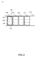
- FIG. 3 illustrates cross section B-B along line B-B on figure 1 .
- one conveying surface 202 being a cross-belt is provided for each of the illustrated carriages 309.
- two or more cross-belts placed in tandem in the conveying direction 308, thus after each other, on each carriage may be used or preferred.
- the conveying direction 308 is the direction in which the conveying surfaces moves in the track 104 of the sorter of the sorting system.
- the track 104 comprises a sorter chassis supported by supports 302 above a floor 304.
- the figure illustrates the top-load loading station 106 which is adapted to load an item onto a predetermined cross-belt in a direction from a loading level which is higher than, in a vertical direction, such as at least 30, 50 or 100 mm higher than, an item supporting level 310 of the predetermined cross-belt and towards the predetermined cross-belt in response to an identification of the item.
- a loading level which is higher than, in a vertical direction, such as at least 30, 50 or 100 mm higher than, an item supporting level 310 of the predetermined cross-belt and towards the predetermined cross-belt in response to an identification of the item.
- This is illustrated with the distance 306 between the conveying surfaces 210 and a lowermost level of a loading end of the top-load loading station.
- FIG. 4 is a top view of the top-load loading station 106 with a diverter 408.
- the illustrated top-load loading station comprises three separate conveyors 402, 404, 406 arranged in tandem.
- the diverter 408 is adapted to divert the item so as for the item to be loaded by the top-load loading station onto the first side 204 or the second side 206 of the cross-belt 202 in response to the identification of the item.
- the conveying surface may comprise a further side, part or area and such further side, part or area is provided with the reference number 208.
- the diverter 408 is positioned towards a loading end of the top-load loading station 106 and specifically shown positioned at the second last conveyor 404 of the conveyors 402, 404, 406 arranged and shown in tandem.
- the arrow with the reference number 405 pointing to the right side illustrates the direction 405 of items moved by the top-load loading station and towards the conveying surfaces of the sorter.
- the conveyor 406 at the loading end can be referred to as an end-most conveyor of the top-load loading station.
- the top-load loading station extends in the same or substantially in the same longitudinal direction as the sorter track. In particular it is illustrated that at least the end-most conveyor 406 extends in the same direction as the sorter track 104.
- the three last conveyors 402, 404, 406 are provided for movement of the items towards the loading end in the direction 405, which direction 405, at least when seen in a top view, is the same direction as the conveying direction 308 of the conveying surfaces 210.
- one or more or all of the conveyor(s), particular the last ones, of the top-load loading station may be provided in an acute angle relatively to the sorter track, but this may or may not, and as an example, require additional equipment for achieving a given orientation of an item on a conveying surface. It may be preferred to be able to load an item onto a predetermined conveying surface, and in particular onto a predetermined side or part of such conveying surface, with a minimum of change of position and/or orientation of the item prior to and/or during and/or after the process of loading and until the item is to be discharged towards a given side of the sorter track 104. It may be seen as a possible advantage of the system and method described herein that such minimum of change is enabled.
- a conveyor width 410 of at least the end most conveyor 406 of the top-load loading station is equal to a or substantially equal to, such as slightly narrower or wider than, a conveying surface width 412 of the below sorter.
- FIG. 5 is the diverter 408 of figure 4 shown without the loading station and the sorting system.
- the diverter is illustrated as two moveable plates 502, 504, capable of diverting an item by pushing the item sideways as illustrated with the dashed arrows. This is provided by moving the plates to their dashed positions and thus for an item to be moved relatively to a surface of a conveyor means supporting the item. The item is then moved sideways on the conveyor means.
- the conveyor means could be a conveyor belt, such as the belt 404, or a roller conveyor for conveying and supporting the item towards the loading end of the top-load loading station.
- FIG. 6 is a top view which illustrates another embodiment of a diverter comprising moveable plates 603, 604.
- the plates can be rotated as illustrated by the dashed arrows to the dashed position and thus in order for an item to be moved relatively to a surface of the conveyor means 404 and 406.
- the diverter in figure 6 is provided for diverting an item so as for the diverted item to be loaded by the top-load loading station onto the first side 204 or the second side 206 of the cross-belt 202.
- FIG. 7 illustrates a further embodiment of a diverter seen from a top view.
- the diverter 702 is a rotational diverter which is adapted to divert the item relatively to a fixed point, such as centre of an axis of rotation 710 of the rotational diverter 702.
- the diversion is provided by the conveyor means being able to rotate between a midposition shown with undashed lines and left and right positions, 708 and 706, respectively, shown with dashed lines.
- the item can be diverted to any of the positions, parts or sides 204, 206 or 208 on the conveying surface.
- a diversion range 712 of the rotational converter is configured to enable loading an item onto a predetermined part across the width of the conveying surface 210, which in the present embodiment is illustrated as a crossbelt 202.
- An alternative type may comprise a diverter positioned in a middle of a conveyor means of the top-load loading station and diverting items towards either a right or a left side.
- the diverter 408, 602, 702 is positioned downstream of, i.e. after, an item identification means, such as a barcode scanner for identification of the item and positioned prior to a position of the item on the system where the item is received on one of the conveying surfaces.
- a top-load loading station with a diverter adapted to divert the item so as for the item to be loaded by the top-load loading station onto, e.g., the first side 204 or the second side 206 of the cross-belt 202, the diverter 408, 602, 702 is provided with a conveying surface width 410, see figure 4 , and/or a diversion range 712 for changing the position of the item in order to load the item on the predetermined part of the conveying surface.
- FIG. 8 is an illustration of an item 808 which is diverted towards a first side as illustrated at the reference number 804 and an illustration of an item which is diverted towards a second side as illustrated at the reference number 806.
- the system includes position changing means, such as the diverter, for changing the position of the item in order to load the item on the predetermined part or side of the conveying surface of the sorter.
- position changing means such as the diverter
- the system disclosed herein is able to load the item directly onto the correct side or part of the conveying surface.
- the system disclosed herein also includes determination means, such as a computerized controller, for determining which part or side of the conveying surface a particular item should most efficiently be positioned on.
- determination means such as a computerized controller, for determining which part or side of the conveying surface a particular item should most efficiently be positioned on.
- Such determination can be provided in response to which side of the sorting track a given discharge for the particular item is placed, which information is statically or dynamically present in an overall sorting system control system as generally known from reference systems, and/or, e.g., in response to which of 2 side by side items is to be discharged firstly along the conveying direction of the track, and/or to which side this is to occur and/or, e.g., which side or part of a particular conveying surface is possibly already occupied.
- the system disclosed herein may also be equipped with occupation determination means, such as a camera and/or means for remembering, e.g., if any items are already placed on a given conveying surface to be loaded and/or which size, or other characteristics such as weight, of one or more items are already placed on which parts or sides of one or more conveying surfaces.
- occupation determination means such as a camera and/or means for remembering, e.g., if any items are already placed on a given conveying surface to be loaded and/or which size, or other characteristics such as weight, of one or more items are already placed on which parts or sides of one or more conveying surfaces.
- FIG. 9 illustrates a method of sorting items with a cross-belt sorting system comprising at least one loading station 106, a plurality of cross-belts which are adapted for moving in a conveying direction in a sorter track and adapted for receiving an item 808 from the loading station.
- the method comprises identifying the item, with an item identification means, such as a barcode scanner 903, for providing an identification of the item, as illustrated at the reference number 902, to obtain an identification of the item, loading the item, as illustrated at the reference number 904, onto a predetermined cross-belt 202, which loading is carried out in a direction from a loading level which is higher than an item supporting level of the predetermined cross-belt and towards the predetermined cross-belt. Receiving the item on the cross-belt is illustrated at the reference number 906.
- an item identification means such as a barcode scanner 903
- the item is loaded onto the predetermined cross-belt and diverted by the top-load loading station onto a first side 204 or a second side 206 of a conveying surface of said predetermined cross-belt in response to said identification of said item.
- cross-belts are shown in top view with respectively 0, 3, 2 and 2, side by side items on each cross-belt 202.
- the items have been loaded onto the conveying surfaces to be positioned in their side by side positions as illustrated with the top-load loading station 106. This has been provided while the conveying surfaces are moving in the track at their travelling speed in the track of e.g. 0.5 meter per second, 1 m/s, 1.5 m/s, 2 m/s or even at 3 m/s.
- cross-belt sorting system 102 for side by side items 808 in which system items are loaded onto their side by side position by one or more top-load loading stations 106, 108 in response to an identification of the items.
Landscapes
- Engineering & Computer Science (AREA)
- Mechanical Engineering (AREA)
- Discharge Of Articles From Conveyors (AREA)
- Branching, Merging, And Special Transfer Between Conveyors (AREA)
- Feeding Of Articles To Conveyors (AREA)
Claims (17)
- Système de tri (102) à bandes croisées pour trier des articles, le système comprenant- au moins une station de chargement,- une pluralité de réceptacles de déchargement (110),- au moins un moyen d'identification d'articles, tel qu'un lecteur de codes-barres (903), pour assurer une identification de l'article,- une pluralité de surfaces de transport (210) adaptées pour se déplacer dans une direction de transport (308) dans une voie (104) de tri et adaptées pour recevoir un ou plusieurs articles (808) provenant de ladite station de chargement et pour transporter lesdits un ou plusieurs articles le long de la voie jusqu'à un réceptacle de déchargement parmi ladite pluralité de réceptacles de déchargement et pour décharger lesdits un ou plusieurs articles de la voie vers le réceptacle de déchargement en réponse à l'identification desdits un ou plusieurs articles,- ladite pluralité de surfaces de transport (210) possédant un premier côté (204) et un deuxième côté (206), le premier et le deuxième côté étant relatifs à une limite imaginaire entre des côtés, des parties ou des zones de la surface de transport se trouvant côte à côte, où la limite imaginaire est orientée dans la direction de transport ou essentiellement dans la direction de transport (308),- lesdites surfaces de transport (210) étant des bandes croisées (202), et- chacune desdites bandes croisées étant adaptée pour transporter deux ou plusieurs articles dans ladite direction de transport, et- ledit système de tri étant adapté pour que lesdits deux ou plusieurs articles soient positionnés sur une seule bande croisée et soient positionnés côte à côte dans une direction transversale à la direction de transport, caractérisé en ce que- ladite au moins une station de chargement est une station de chargement à chargement par le haut (106) pour charger un article (808) sur une bande croisée prédéterminée dans une direction allant depuis un niveau de chargement qui, dans une direction verticale, est plus élevé, par exemple au moins 30, 50 ou 100 mm plus élevé, qu'un niveau supportant l'article (310) de ladite bande croisée prédéterminée et vers ladite bande croisée prédéterminée, et- ladite station de chargement à chargement par le haut comprend un déviateur pour dévier ledit article vers un premier côté (204) ou un deuxième côté (206) d'une surface de transport de ladite bande croisée prédéterminée en réponse à ladite identification dudit article, et- la station de chargement à chargement par le haut est adaptée pour charger ledit article sur ledit premier ou deuxième côté en réponse à ladite identification.
- Le système selon la revendication 1, dans lequel la station de chargement à chargement par le haut (106) est positionnée à une distance (306) au-dessus des surfaces de transport (210) telle qu'un niveau le plus bas d'une extrémité de chargement de la station de chargement à chargement par le haut soit positionné au-dessus, par exemple au moins 30, 50 ou 100 mm au-dessus, d'un niveau supportant l'article (310) d'une surface de transport (210) d'articles desdites bandes croisées (202).
- Le système selon une quelconque des revendications 1 ou 2, dans lequel la station de chargement à chargement par le haut (106) est disposée et adaptée de manière à permettre à l'article (808) d'être chargé avec un vecteur de vitesse dans la direction de transport (308).
- Le système selon l'une quelconque des revendications précédentes, dans lequel la station de chargement à chargement par le haut (106) est positionnée de manière à ce que la voie (104) avec la pluralité de surfaces de transport (210) passe en dessous, de manière à ce que la voie (104) de tri traverse en dessous de la station de chargement à chargement par le haut (106).
- Le système selon l'une quelconque des revendications précédentes, dans lequel la station de chargement à chargement par le haut (106) est positionnée de manière à ce que la voie (104) avec la pluralité de surfaces de transport (210) s'étende longitudinalement dans la même ou essentiellement la même direction longitudinale qu'au moins une section longitudinale de la station de chargement à chargement par le haut, de manière à s'étendre dans la même ou essentiellement la même direction longitudinale qu'au moins une partie de la station de chargement à chargement par le haut en direction d'une extrémité de chargement de la station de chargement à chargement par le haut.
- Le système selon l'une quelconque des revendications précédentes, dans lequel le déviateur (408, 602), tel qu'une plaque mobile (502, 603), est adapté pour dévier l'article (808) par rapport à une surface d'un moyen de transport (404) supportant l'article.
- Le système selon l'une quelconque des revendications précédentes, dans lequel le déviateur (702), tel qu'un déviateur rotatif, est adapté pour dévier l'article par rapport à un point fixe, tel que le centre d'un axe de rotation (710) du déviateur rotatif.
- Le système selon l'une quelconque des revendications précédentes, dans lequel le déviateur (408, 602, 702) est positionné en aval du moyen d'identification d'articles, tel qu'un lecteur de codes-barres (903), pour l'identification de l'article (808), et le déviateur est positionné avant une position de l'article sur le système où l'article est reçu sur l'une desdites surfaces de transport (210).
- Le système selon l'une quelconque des revendications précédentes, dans lequel la station de chargement à chargement par le haut (106) comprend une pluralité de transporteurs (402, 404, 406) séparés disposés en tandem.
- Le système selon l'une quelconque des revendications précédentes, dans lequel le déviateur (408, 602, 702) est positionné en direction d'une extrémité de la station de chargement à chargement par le haut (106), par exemple compris dans ou au niveau d'un ou plusieurs des quatre derniers de ladite pluralité de transporteurs disposés en tandem.
- Le système selon l'une quelconque des revendications précédentes, dans lequel ledit système comprend une station de chargement 1 (106) et une station de chargement 2 (108), dans lequel la station de chargement 2 est une station de chargement à chargement par le haut, la station de chargement à chargement par le haut étant positionnée au niveau d'une position le long de la voie de tri de manière à charger des articles sur les surfaces de transport au niveau d'une position située après la station de chargement 1, par rapport à la direction de transport (308).
- Méthode de tri d'articles avec un système de tri à bandes croisées comprenant au moins une station de chargement (106), une pluralité de réceptacles de déchargement (110), une pluralité de surfaces de transport (210) étant des bandes croisées qui sont adaptées pour se déplacer dans une direction de transport (308) dans une voie (104) de tri et adaptées pour recevoir un article (808) provenant de ladite station de chargement et pour transporter ledit article dans la voie jusqu'à un réceptacle de déchargement parmi ladite pluralité de réceptacles de déchargement et pour décharger ledit article de la voie vers le réceptacle de déchargement en réponse à une identification dudit article, ladite pluralité de surfaces de transport (210) possédant un premier côté (204) et un deuxième côté (206), le premier et le deuxième côté étant relatifs à une limite imaginaire entre des côtés, des parties ou des zones de la surface de transport se trouvant côte à côte, où la limite imaginaire est orientée dans la direction de transport ou essentiellement dans la direction de transport (308), ladite méthode comprenant- l'identification (902) dudit article pour obtenir ladite identification dudit article,- le chargement de l'article sur une bande croisée prédéterminée à l'aide de ladite station de chargement, et- la réception de l'article sur la bande croisée prédéterminée depuis ladite station de chargement, et- le transport de l'article dans la direction de transport sur ladite bande croisée prédéterminée jusqu'au dit réceptacle de déchargement,
caractérisée en ce que- le chargement (904) de l'article sur la bande croisée prédéterminée est effectué dans une direction allant depuis un niveau de chargement qui, dans une direction verticale, est plus élevé, par exemple au moins 30, 50 ou 100 mm plus élevé, qu'un niveau supportant l'article (310) de ladite bande croisée prédéterminée et vers ladite bande croisée prédéterminée, et- le chargement de l'article sur une bande croisée prédéterminée inclut le chargement et la déviation de l'article à l'aide de ladite station de chargement à chargement par le haut vers un premier côté ou un deuxième côté d'une surface de transport de ladite bande croisée prédéterminée en réponse à ladite identification dudit article, et- la réception de l'article provenant de ladite station de chargement à chargement par le haut inclut la réception de l'article sur ledit premier côté ou deuxième côté de la surface de transport de ladite bande croisée prédéterminée. - La méthode selon la revendication 12, dans laquelle le chargement dudit article sur ledit premier côté (204) ou ledit deuxième côté (206) de ladite surface de support de ladite bande croisée prédéterminée est en outre réalisé en réponse à une identification d'une pluralité d'articles successifs devant être chargés sur le système de tri (102) par la station de chargement à chargement par le haut (106).
- La méthode selon la revendication 12 ou 13, dans laquelle le chargement dudit article sur ledit premier côté (204) ou ledit deuxième côté (206) de ladite surface de transport (210) de ladite bande croisée prédéterminée est en outre réalisé en réponse à une position actuelle d'un déviateur (408, 602, 702).
- La méthode selon l'une quelconque des revendications 12 à 14, dans laquelle ladite identification détermine si un réceptacle de déchargement préférentiel pour l'article est positionné au niveau de la voie de tri la plus adjacente au premier côté (204) ou la plus adjacente au deuxième côté (206) des surfaces de transport se déplaçant dans la voie de tri quand ladite surface de transport arrive au niveau du réceptacle de déchargement préférentiel.
- La méthode selon l'une quelconque des revendications 12 à 15, dans laquelle ledit système comprend une station de chargement 1 (106) et une station de chargement 2 (108), dans laquelle la station de chargement 2 est une station de chargement à chargement par le haut, la station de chargement à chargement par le haut étant positionnée au niveau d'une position le long de la voie de tri de manière à charger des articles sur les surfaces de transport au niveau d'une position située après la station de chargement 1, par rapport à la direction de transport, et dans laquelle ladite méthode comprend en outre le déplacement de la surface de transport d'une bande croisée dans une direction de déchargement transversale à la direction de transport (308) avant que ladite surface de transport (210) arrive au niveau de la station de chargement 2, de manière à déplacer un article chargé sur le premier ou le deuxième côté de la bande croisée par la station de chargement 1 dans la direction de déchargement avant que ladite surface de support arrive à la station de chargement 2.
- La méthode selon l'une quelconque des revendications 12 à 16, dans laquelle la réception de l'article sur ledit premier côté (204) ou ledit deuxième côté (206) comprend le fait que, à la réception de l'article, la bande croisée prédéterminée reste immobile ou essentiellement immobile dans une direction transversale à la direction de transport, c'est-à-dire que la bande de la bande croisée n'est pas entraînée ou n'est éventuellement que légèrement entraînée dans une direction transversale à la direction de transport des surfaces de transport.
Applications Claiming Priority (1)
| Application Number | Priority Date | Filing Date | Title |
|---|---|---|---|
| DKPA201170448A DK177381B1 (en) | 2011-08-16 | 2011-08-16 | Cross-belt sorting system |
Publications (2)
| Publication Number | Publication Date |
|---|---|
| EP2559639A1 EP2559639A1 (fr) | 2013-02-20 |
| EP2559639B1 true EP2559639B1 (fr) | 2014-12-31 |
Family
ID=46614390
Family Applications (1)
| Application Number | Title | Priority Date | Filing Date |
|---|---|---|---|
| EP12179858.1A Active EP2559639B1 (fr) | 2011-08-16 | 2012-08-09 | Système de tri à bandes croisées |
Country Status (7)
| Country | Link |
|---|---|
| US (1) | US9145272B2 (fr) |
| EP (1) | EP2559639B1 (fr) |
| JP (1) | JP6120381B2 (fr) |
| CN (1) | CN103842270B (fr) |
| DK (1) | DK177381B1 (fr) |
| ES (1) | ES2533301T3 (fr) |
| WO (1) | WO2013023661A1 (fr) |
Families Citing this family (20)
| Publication number | Priority date | Publication date | Assignee | Title |
|---|---|---|---|---|
| ES2944843T3 (es) * | 2013-07-19 | 2023-06-26 | Compac Tech Limited | Aparato de transporte de artículos |
| BR112017008869B1 (pt) * | 2014-10-29 | 2021-12-28 | Fives Intralogistics S.P.A. Con Socio Unico | Dispositivo para alimentar artigos a uma máquina de classificação e máquina de classificação |
| DE102015203553B4 (de) | 2015-02-27 | 2023-08-17 | Körber Supply Chain Logistics Gmbh | Zuführen eines Stückgutstroms zu einem anderen Stückgutstrom |
| CN104944039A (zh) * | 2015-06-30 | 2015-09-30 | 深圳市欣视景科技有限公司 | 一种全自动交叉分拣装置 |
| DE202016102149U1 (de) * | 2016-04-22 | 2017-07-26 | Kuka Systems Gmbh | Fertigungsanlage |
| US11416695B2 (en) | 2017-04-18 | 2022-08-16 | Berkshire Grey Operating Company, Inc. | Systems and methods for distributing induction of objects to a plurality of object processing systems |
| US11055504B2 (en) | 2017-04-18 | 2021-07-06 | Berkshire Grey, Inc. | Systems and methods for separating objects using a vacuum roller with one or more object processing systems |
| US11205059B2 (en) | 2017-04-18 | 2021-12-21 | Berkshire Grey, Inc. | Systems and methods for separating objects using conveyor transfer with one or more object processing systems |
| US11301654B2 (en) | 2017-04-18 | 2022-04-12 | Berkshire Grey Operating Company, Inc. | Systems and methods for limiting induction of objects to one or more object processing systems |
| US11373134B2 (en) | 2018-10-23 | 2022-06-28 | Berkshire Grey Operating Company, Inc. | Systems and methods for dynamic processing of objects with data verification |
| US11080496B2 (en) | 2017-04-18 | 2021-08-03 | Berkshire Grey, Inc. | Systems and methods for separating objects using vacuum diverts with one or more object processing systems |
| CA3060257C (fr) * | 2017-04-18 | 2023-03-07 | Berkshire Grey, Inc. | Systemes et procedes de traitement d'objets comprenant des stations de distribution efficaces dans l'espace et un traitement de sortie automatise |
| US11200390B2 (en) | 2017-04-18 | 2021-12-14 | Berkshire Grey, Inc. | Systems and methods for separating objects using drop conveyors with one or more object processing systems |
| FR3068268A1 (fr) * | 2017-06-29 | 2019-01-04 | Crescendi | Installation et procede de manutention et de triage automatique a haute cadence d'objets, de toutes formes, y compris instables et volumineux |
| CN109261529A (zh) * | 2018-09-26 | 2019-01-25 | 深圳市朗耀电子商务有限公司 | 一种双层交叉带分拣机及其空车检测的方法和装置 |
| US20220297160A1 (en) * | 2019-05-24 | 2022-09-22 | Laitram, L.L.C. | Compact sorter |
| CN110841924B (zh) * | 2019-10-30 | 2024-02-09 | 苏州金峰物联网技术有限公司 | 多层交叉带分拣设备及其分拣方法 |
| CN111017483A (zh) * | 2019-12-12 | 2020-04-17 | 苏州金峰物流设备有限公司 | 输送面可升降交叉带分拣小车、交叉带分拣系统及其分拣方法 |
| CN113578783B (zh) * | 2021-08-02 | 2023-08-01 | 深圳市镖锔科技有限公司 | 一种基于物联网的智能仓储分拣设备 |
| EP4234447A1 (fr) | 2022-02-28 | 2023-08-30 | Körber Supply Chain Logistics GmbH | Guidage combiné de flux de marchandises |
Family Cites Families (21)
| Publication number | Priority date | Publication date | Assignee | Title |
|---|---|---|---|---|
| US3237743A (en) * | 1963-08-12 | 1966-03-01 | Fmc Corp | Slide reject conveyor |
| DK150740C (da) * | 1977-09-01 | 1988-02-08 | Gram Brdr As | Fremgangsmaade til brug ved overfoering af genstande fra en kontinuert bevaeget tilfoerselstransportoer og til en modtagertransportoer samt transportanlaeg til brug ved udoevelse af fremgangsmaaden |
| US4815582A (en) * | 1981-12-24 | 1989-03-28 | Francesco Canziani | Feeding apparatus particularly for machines for the conveyance and sorting of objects |
| JP2695781B2 (ja) | 1987-04-30 | 1998-01-14 | 株式会社日立製作所 | 荷の並べ換え装置 |
| JPH02158810A (ja) | 1988-12-12 | 1990-06-19 | Hitachi Ltd | 台車の搬送制御方法 |
| NL8900975A (nl) | 1989-04-19 | 1990-11-16 | Rapistan Van Der Lande Bv | Transportinrichting. |
| US5054601A (en) | 1989-09-19 | 1991-10-08 | Quipp, Incorporated | Sorting conveyor |
| US5388681A (en) | 1992-10-19 | 1995-02-14 | United Parcel Service Of America, Inc. | Inflatable conveyor belt |
| JPH0725447A (ja) | 1993-07-08 | 1995-01-27 | Toyo Kanetsu Kk | 仕分け方法及び装置 |
| JP3094853B2 (ja) * | 1995-07-26 | 2000-10-03 | 株式会社ダイフク | 仕分け設備 |
| IT1276145B1 (it) | 1995-11-16 | 1997-10-27 | Cml Handling Technology S P A | Apparecchiatura smistatrice con celle di trasporto degli oggetti su piani sovrapposti |
| IT1297026B1 (it) * | 1997-12-29 | 1999-08-03 | Cml Handling Technology S P A | Metodo ed apparecchiatura ad elevata produttivita' per lo smistamento dei pacchi |
| DE19801706A1 (de) | 1998-01-17 | 1999-07-22 | Axmann Foerdertechnik | Vorrichtung zum Sortieren von Stückgütern |
| JPH11286328A (ja) * | 1998-03-30 | 1999-10-19 | Hokushoo Kk | 小物類の仕分け装置 |
| IT1301696B1 (it) * | 1998-06-12 | 2000-07-07 | Cml Handling Technology S P A | Metodo ed apparecchiatura per il caricamento automatico di piu'oggetti ordinati, sulla stessa unita' di una macchina smistatrice |
| US20030221935A1 (en) * | 1998-12-01 | 2003-12-04 | Crisplant A/S | Conveyor/sorter system, a loading conveyor and a control system for such conveyors |
| EP1135315A1 (fr) | 1998-12-01 | 2001-09-26 | Crisplant A/S | Systeme de transporteur et de tri, transporteur de chargement et systeme de commande de tels transporteurs |
| DE19929529A1 (de) * | 1999-06-28 | 2001-01-04 | Beumer Maschf Gmbh & Co Kg | Stückgut-Fördereinrichtung |
| US6478138B1 (en) * | 1999-10-04 | 2002-11-12 | Rapistan Systems Advertising Corp. | Double width crossbelt sorter |
| US6889814B2 (en) * | 2001-05-30 | 2005-05-10 | Rapistan Systems Advertising Corp. | Article sortation system |
| DE102008037261A1 (de) | 2008-08-11 | 2010-02-25 | Siemens Aktiengesellschaft | System zur Stückgutsortierung |
-
2011
- 2011-08-16 DK DKPA201170448A patent/DK177381B1/en active
-
2012
- 2012-08-09 US US14/237,661 patent/US9145272B2/en active Active
- 2012-08-09 JP JP2014525321A patent/JP6120381B2/ja active Active
- 2012-08-09 WO PCT/DK2012/050290 patent/WO2013023661A1/fr active Application Filing
- 2012-08-09 ES ES12179858.1T patent/ES2533301T3/es active Active
- 2012-08-09 CN CN201280039979.2A patent/CN103842270B/zh active Active
- 2012-08-09 EP EP12179858.1A patent/EP2559639B1/fr active Active
Also Published As
| Publication number | Publication date |
|---|---|
| WO2013023661A1 (fr) | 2013-02-21 |
| CN103842270A (zh) | 2014-06-04 |
| JP2014521575A (ja) | 2014-08-28 |
| EP2559639A1 (fr) | 2013-02-20 |
| ES2533301T3 (es) | 2015-04-09 |
| CN103842270B (zh) | 2016-01-20 |
| JP6120381B2 (ja) | 2017-04-26 |
| DK177381B1 (en) | 2013-03-04 |
| US20140158505A1 (en) | 2014-06-12 |
| US9145272B2 (en) | 2015-09-29 |
Similar Documents
| Publication | Publication Date | Title |
|---|---|---|
| EP2559639B1 (fr) | Système de tri à bandes croisées | |
| US9896280B2 (en) | Stacked tilt tray and cross-belt sorting system | |
| EP1220719B1 (fr) | Trieuse a bandes croisees | |
| US9630785B2 (en) | Buffer conveyor having parallel tracks | |
| US8037994B2 (en) | Apparatus and method for sorting non-sorted containers in an order-picking system | |
| CN107472852A (zh) | 用于在递送路线的不同地点递送托运物的递送车辆和方法 | |
| DK2976263T3 (en) | Device for processing sorting materials | |
| MX2008014501A (es) | Aparatos y metodos de banda transportadora de clasificacion. | |
| CN108569529B (zh) | 用于运输货物部件的输送系统和方法 | |
| US20160185533A1 (en) | Operating a sorting system for items having variating size | |
| US20140039669A1 (en) | Method of transporting and sorting and system for exercising the method | |
| US20190168972A1 (en) | Device for loading and unloading rail-guided suspended conveyor systems | |
| US20230398574A1 (en) | Mobile sorting unit | |
| WO2013041099A1 (fr) | Procédé de manutention d'objets dans un aéroport, et système de manutention | |
| US11420833B2 (en) | Linear sorter having variably running cross-belt supports | |
| EP3191386B1 (fr) | Procédé et système pour établir un ordre d'une séquence d'alimentation | |
| US5566834A (en) | Method and system for transport of good and luggage in an airport or similar facility | |
| WO1990009943A1 (fr) | Procede et systeme de transport interne de bagages dans les aeroports de taille importante | |
| JP2007031092A (ja) | 荷搬送設備 |
Legal Events
| Date | Code | Title | Description |
|---|---|---|---|
| PUAI | Public reference made under article 153(3) epc to a published international application that has entered the european phase |
Free format text: ORIGINAL CODE: 0009012 |
|
| AK | Designated contracting states |
Kind code of ref document: A1 Designated state(s): AL AT BE BG CH CY CZ DE DK EE ES FI FR GB GR HR HU IE IS IT LI LT LU LV MC MK MT NL NO PL PT RO RS SE SI SK SM TR |
|
| AX | Request for extension of the european patent |
Extension state: BA ME |
|
| 17P | Request for examination filed |
Effective date: 20130618 |
|
| RBV | Designated contracting states (corrected) |
Designated state(s): AL AT BE BG CH CY CZ DE DK EE ES FI FR GB GR HR HU IE IS IT LI LT LU LV MC MK MT NL NO PL PT RO RS SE SI SK SM TR |
|
| GRAP | Despatch of communication of intention to grant a patent |
Free format text: ORIGINAL CODE: EPIDOSNIGR1 |
|
| RIC1 | Information provided on ipc code assigned before grant |
Ipc: B65G 47/76 20060101ALI20140121BHEP Ipc: B65G 47/96 20060101ALI20140121BHEP Ipc: B65G 17/34 20060101AFI20140121BHEP |
|
| INTG | Intention to grant announced |
Effective date: 20140210 |
|
| GRAP | Despatch of communication of intention to grant a patent |
Free format text: ORIGINAL CODE: EPIDOSNIGR1 |
|
| INTG | Intention to grant announced |
Effective date: 20140710 |
|
| GRAS | Grant fee paid |
Free format text: ORIGINAL CODE: EPIDOSNIGR3 |
|
| GRAA | (expected) grant |
Free format text: ORIGINAL CODE: 0009210 |
|
| AK | Designated contracting states |
Kind code of ref document: B1 Designated state(s): AL AT BE BG CH CY CZ DE DK EE ES FI FR GB GR HR HU IE IS IT LI LT LU LV MC MK MT NL NO PL PT RO RS SE SI SK SM TR |
|
| REG | Reference to a national code |
Ref country code: GB Ref legal event code: FG4D Ref country code: CH Ref legal event code: EP |
|
| REG | Reference to a national code |
Ref country code: IE Ref legal event code: FG4D |
|
| REG | Reference to a national code |
Ref country code: AT Ref legal event code: REF Ref document number: 704246 Country of ref document: AT Kind code of ref document: T Effective date: 20150215 |
|
| REG | Reference to a national code |
Ref country code: DE Ref legal event code: R096 Ref document number: 602012004617 Country of ref document: DE Effective date: 20150219 |
|
| REG | Reference to a national code |
Ref country code: NL Ref legal event code: T3 |
|
| REG | Reference to a national code |
Ref country code: ES Ref legal event code: FG2A Ref document number: 2533301 Country of ref document: ES Kind code of ref document: T3 Effective date: 20150409 |
|
| PG25 | Lapsed in a contracting state [announced via postgrant information from national office to epo] |
Ref country code: LT Free format text: LAPSE BECAUSE OF FAILURE TO SUBMIT A TRANSLATION OF THE DESCRIPTION OR TO PAY THE FEE WITHIN THE PRESCRIBED TIME-LIMIT Effective date: 20141231 Ref country code: FI Free format text: LAPSE BECAUSE OF FAILURE TO SUBMIT A TRANSLATION OF THE DESCRIPTION OR TO PAY THE FEE WITHIN THE PRESCRIBED TIME-LIMIT Effective date: 20141231 Ref country code: NO Free format text: LAPSE BECAUSE OF FAILURE TO SUBMIT A TRANSLATION OF THE DESCRIPTION OR TO PAY THE FEE WITHIN THE PRESCRIBED TIME-LIMIT Effective date: 20150331 |
|
| REG | Reference to a national code |
Ref country code: LT Ref legal event code: MG4D |
|
| PG25 | Lapsed in a contracting state [announced via postgrant information from national office to epo] |
Ref country code: SE Free format text: LAPSE BECAUSE OF FAILURE TO SUBMIT A TRANSLATION OF THE DESCRIPTION OR TO PAY THE FEE WITHIN THE PRESCRIBED TIME-LIMIT Effective date: 20141231 Ref country code: RS Free format text: LAPSE BECAUSE OF FAILURE TO SUBMIT A TRANSLATION OF THE DESCRIPTION OR TO PAY THE FEE WITHIN THE PRESCRIBED TIME-LIMIT Effective date: 20141231 Ref country code: HR Free format text: LAPSE BECAUSE OF FAILURE TO SUBMIT A TRANSLATION OF THE DESCRIPTION OR TO PAY THE FEE WITHIN THE PRESCRIBED TIME-LIMIT Effective date: 20141231 Ref country code: LV Free format text: LAPSE BECAUSE OF FAILURE TO SUBMIT A TRANSLATION OF THE DESCRIPTION OR TO PAY THE FEE WITHIN THE PRESCRIBED TIME-LIMIT Effective date: 20141231 Ref country code: GR Free format text: LAPSE BECAUSE OF FAILURE TO SUBMIT A TRANSLATION OF THE DESCRIPTION OR TO PAY THE FEE WITHIN THE PRESCRIBED TIME-LIMIT Effective date: 20150401 |
|
| REG | Reference to a national code |
Ref country code: AT Ref legal event code: MK05 Ref document number: 704246 Country of ref document: AT Kind code of ref document: T Effective date: 20141231 |
|
| PG25 | Lapsed in a contracting state [announced via postgrant information from national office to epo] |
Ref country code: SK Free format text: LAPSE BECAUSE OF FAILURE TO SUBMIT A TRANSLATION OF THE DESCRIPTION OR TO PAY THE FEE WITHIN THE PRESCRIBED TIME-LIMIT Effective date: 20141231 Ref country code: CZ Free format text: LAPSE BECAUSE OF FAILURE TO SUBMIT A TRANSLATION OF THE DESCRIPTION OR TO PAY THE FEE WITHIN THE PRESCRIBED TIME-LIMIT Effective date: 20141231 Ref country code: RO Free format text: LAPSE BECAUSE OF FAILURE TO SUBMIT A TRANSLATION OF THE DESCRIPTION OR TO PAY THE FEE WITHIN THE PRESCRIBED TIME-LIMIT Effective date: 20141231 |
|
| REG | Reference to a national code |
Ref country code: FR Ref legal event code: PLFP Year of fee payment: 4 |
|
| PG25 | Lapsed in a contracting state [announced via postgrant information from national office to epo] |
Ref country code: AT Free format text: LAPSE BECAUSE OF FAILURE TO SUBMIT A TRANSLATION OF THE DESCRIPTION OR TO PAY THE FEE WITHIN THE PRESCRIBED TIME-LIMIT Effective date: 20141231 Ref country code: PL Free format text: LAPSE BECAUSE OF FAILURE TO SUBMIT A TRANSLATION OF THE DESCRIPTION OR TO PAY THE FEE WITHIN THE PRESCRIBED TIME-LIMIT Effective date: 20141231 Ref country code: IS Free format text: LAPSE BECAUSE OF FAILURE TO SUBMIT A TRANSLATION OF THE DESCRIPTION OR TO PAY THE FEE WITHIN THE PRESCRIBED TIME-LIMIT Effective date: 20150430 |
|
| REG | Reference to a national code |
Ref country code: DE Ref legal event code: R097 Ref document number: 602012004617 Country of ref document: DE |
|
| PG25 | Lapsed in a contracting state [announced via postgrant information from national office to epo] |
Ref country code: DK Free format text: LAPSE BECAUSE OF FAILURE TO SUBMIT A TRANSLATION OF THE DESCRIPTION OR TO PAY THE FEE WITHIN THE PRESCRIBED TIME-LIMIT Effective date: 20141231 Ref country code: EE Free format text: LAPSE BECAUSE OF FAILURE TO SUBMIT A TRANSLATION OF THE DESCRIPTION OR TO PAY THE FEE WITHIN THE PRESCRIBED TIME-LIMIT Effective date: 20141231 |
|
| PLBE | No opposition filed within time limit |
Free format text: ORIGINAL CODE: 0009261 |
|
| STAA | Information on the status of an ep patent application or granted ep patent |
Free format text: STATUS: NO OPPOSITION FILED WITHIN TIME LIMIT |
|
| 26N | No opposition filed |
Effective date: 20151001 |
|
| PG25 | Lapsed in a contracting state [announced via postgrant information from national office to epo] |
Ref country code: SI Free format text: LAPSE BECAUSE OF FAILURE TO SUBMIT A TRANSLATION OF THE DESCRIPTION OR TO PAY THE FEE WITHIN THE PRESCRIBED TIME-LIMIT Effective date: 20141231 |
|
| PG25 | Lapsed in a contracting state [announced via postgrant information from national office to epo] |
Ref country code: MC Free format text: LAPSE BECAUSE OF FAILURE TO SUBMIT A TRANSLATION OF THE DESCRIPTION OR TO PAY THE FEE WITHIN THE PRESCRIBED TIME-LIMIT Effective date: 20141231 Ref country code: LU Free format text: LAPSE BECAUSE OF FAILURE TO SUBMIT A TRANSLATION OF THE DESCRIPTION OR TO PAY THE FEE WITHIN THE PRESCRIBED TIME-LIMIT Effective date: 20150809 |
|
| REG | Reference to a national code |
Ref country code: CH Ref legal event code: PL |
|
| PG25 | Lapsed in a contracting state [announced via postgrant information from national office to epo] |
Ref country code: LI Free format text: LAPSE BECAUSE OF NON-PAYMENT OF DUE FEES Effective date: 20150831 Ref country code: CH Free format text: LAPSE BECAUSE OF NON-PAYMENT OF DUE FEES Effective date: 20150831 |
|
| PG25 | Lapsed in a contracting state [announced via postgrant information from national office to epo] |
Ref country code: BE Free format text: LAPSE BECAUSE OF FAILURE TO SUBMIT A TRANSLATION OF THE DESCRIPTION OR TO PAY THE FEE WITHIN THE PRESCRIBED TIME-LIMIT Effective date: 20141231 |
|
| REG | Reference to a national code |
Ref country code: IE Ref legal event code: MM4A |
|
| PG25 | Lapsed in a contracting state [announced via postgrant information from national office to epo] |
Ref country code: IE Free format text: LAPSE BECAUSE OF NON-PAYMENT OF DUE FEES Effective date: 20150809 |
|
| REG | Reference to a national code |
Ref country code: FR Ref legal event code: PLFP Year of fee payment: 5 |
|
| PG25 | Lapsed in a contracting state [announced via postgrant information from national office to epo] |
Ref country code: MT Free format text: LAPSE BECAUSE OF FAILURE TO SUBMIT A TRANSLATION OF THE DESCRIPTION OR TO PAY THE FEE WITHIN THE PRESCRIBED TIME-LIMIT Effective date: 20141231 |
|
| PG25 | Lapsed in a contracting state [announced via postgrant information from national office to epo] |
Ref country code: SM Free format text: LAPSE BECAUSE OF FAILURE TO SUBMIT A TRANSLATION OF THE DESCRIPTION OR TO PAY THE FEE WITHIN THE PRESCRIBED TIME-LIMIT Effective date: 20141231 Ref country code: BG Free format text: LAPSE BECAUSE OF FAILURE TO SUBMIT A TRANSLATION OF THE DESCRIPTION OR TO PAY THE FEE WITHIN THE PRESCRIBED TIME-LIMIT Effective date: 20141231 Ref country code: HU Free format text: LAPSE BECAUSE OF FAILURE TO SUBMIT A TRANSLATION OF THE DESCRIPTION OR TO PAY THE FEE WITHIN THE PRESCRIBED TIME-LIMIT; INVALID AB INITIO Effective date: 20120809 |
|
| PG25 | Lapsed in a contracting state [announced via postgrant information from national office to epo] |
Ref country code: CY Free format text: LAPSE BECAUSE OF FAILURE TO SUBMIT A TRANSLATION OF THE DESCRIPTION OR TO PAY THE FEE WITHIN THE PRESCRIBED TIME-LIMIT Effective date: 20141231 |
|
| REG | Reference to a national code |
Ref country code: FR Ref legal event code: PLFP Year of fee payment: 6 |
|
| PG25 | Lapsed in a contracting state [announced via postgrant information from national office to epo] |
Ref country code: TR Free format text: LAPSE BECAUSE OF FAILURE TO SUBMIT A TRANSLATION OF THE DESCRIPTION OR TO PAY THE FEE WITHIN THE PRESCRIBED TIME-LIMIT Effective date: 20141231 |
|
| PG25 | Lapsed in a contracting state [announced via postgrant information from national office to epo] |
Ref country code: MK Free format text: LAPSE BECAUSE OF FAILURE TO SUBMIT A TRANSLATION OF THE DESCRIPTION OR TO PAY THE FEE WITHIN THE PRESCRIBED TIME-LIMIT Effective date: 20141231 |
|
| PG25 | Lapsed in a contracting state [announced via postgrant information from national office to epo] |
Ref country code: PT Free format text: LAPSE BECAUSE OF FAILURE TO SUBMIT A TRANSLATION OF THE DESCRIPTION OR TO PAY THE FEE WITHIN THE PRESCRIBED TIME-LIMIT Effective date: 20141231 |
|
| REG | Reference to a national code |
Ref country code: FR Ref legal event code: PLFP Year of fee payment: 7 |
|
| PG25 | Lapsed in a contracting state [announced via postgrant information from national office to epo] |
Ref country code: AL Free format text: LAPSE BECAUSE OF FAILURE TO SUBMIT A TRANSLATION OF THE DESCRIPTION OR TO PAY THE FEE WITHIN THE PRESCRIBED TIME-LIMIT Effective date: 20141231 |
|
| P01 | Opt-out of the competence of the unified patent court (upc) registered |
Effective date: 20230514 |
|
| PGFP | Annual fee paid to national office [announced via postgrant information from national office to epo] |
Ref country code: NL Payment date: 20230821 Year of fee payment: 12 |
|
| PGFP | Annual fee paid to national office [announced via postgrant information from national office to epo] |
Ref country code: IT Payment date: 20230825 Year of fee payment: 12 Ref country code: GB Payment date: 20230822 Year of fee payment: 12 |
|
| PGFP | Annual fee paid to national office [announced via postgrant information from national office to epo] |
Ref country code: FR Payment date: 20230824 Year of fee payment: 12 Ref country code: DE Payment date: 20230821 Year of fee payment: 12 |
|
| PGFP | Annual fee paid to national office [announced via postgrant information from national office to epo] |
Ref country code: ES Payment date: 20231027 Year of fee payment: 12 |