EP2559532A2 - Method and device for producing a translucent multilayer composite building element with integrated façade panel - Google Patents
Method and device for producing a translucent multilayer composite building element with integrated façade panel Download PDFInfo
- Publication number
- EP2559532A2 EP2559532A2 EP12005398A EP12005398A EP2559532A2 EP 2559532 A2 EP2559532 A2 EP 2559532A2 EP 12005398 A EP12005398 A EP 12005398A EP 12005398 A EP12005398 A EP 12005398A EP 2559532 A2 EP2559532 A2 EP 2559532A2
- Authority
- EP
- European Patent Office
- Prior art keywords
- light
- formwork
- panels
- layer
- multilayer composite
- Prior art date
- Legal status (The legal status is an assumption and is not a legal conclusion. Google has not performed a legal analysis and makes no representation as to the accuracy of the status listed.)
- Granted
Links
Images

Classifications
-
- B—PERFORMING OPERATIONS; TRANSPORTING
- B28—WORKING CEMENT, CLAY, OR STONE
- B28B—SHAPING CLAY OR OTHER CERAMIC COMPOSITIONS; SHAPING SLAG; SHAPING MIXTURES CONTAINING CEMENTITIOUS MATERIAL, e.g. PLASTER
- B28B23/00—Arrangements specially adapted for the production of shaped articles with elements wholly or partly embedded in the moulding material; Production of reinforced objects
- B28B23/0037—Arrangements specially adapted for the production of shaped articles with elements wholly or partly embedded in the moulding material; Production of reinforced objects with elements being able to conduct light, e.g. light conducting fibers
-
- B—PERFORMING OPERATIONS; TRANSPORTING
- B28—WORKING CEMENT, CLAY, OR STONE
- B28B—SHAPING CLAY OR OTHER CERAMIC COMPOSITIONS; SHAPING SLAG; SHAPING MIXTURES CONTAINING CEMENTITIOUS MATERIAL, e.g. PLASTER
- B28B19/00—Machines or methods for applying the material to surfaces to form a permanent layer thereon
- B28B19/0015—Machines or methods for applying the material to surfaces to form a permanent layer thereon on multilayered articles
-
- B—PERFORMING OPERATIONS; TRANSPORTING
- B28—WORKING CEMENT, CLAY, OR STONE
- B28B—SHAPING CLAY OR OTHER CERAMIC COMPOSITIONS; SHAPING SLAG; SHAPING MIXTURES CONTAINING CEMENTITIOUS MATERIAL, e.g. PLASTER
- B28B19/00—Machines or methods for applying the material to surfaces to form a permanent layer thereon
- B28B19/003—Machines or methods for applying the material to surfaces to form a permanent layer thereon to insulating material
-
- B—PERFORMING OPERATIONS; TRANSPORTING
- B29—WORKING OF PLASTICS; WORKING OF SUBSTANCES IN A PLASTIC STATE IN GENERAL
- B29C—SHAPING OR JOINING OF PLASTICS; SHAPING OF MATERIAL IN A PLASTIC STATE, NOT OTHERWISE PROVIDED FOR; AFTER-TREATMENT OF THE SHAPED PRODUCTS, e.g. REPAIRING
- B29C39/00—Shaping by casting, i.e. introducing the moulding material into a mould or between confining surfaces without significant moulding pressure; Apparatus therefor
- B29C39/02—Shaping by casting, i.e. introducing the moulding material into a mould or between confining surfaces without significant moulding pressure; Apparatus therefor for making articles of definite length, i.e. discrete articles
- B29C39/10—Shaping by casting, i.e. introducing the moulding material into a mould or between confining surfaces without significant moulding pressure; Apparatus therefor for making articles of definite length, i.e. discrete articles incorporating preformed parts or layers, e.g. casting around inserts or for coating articles
-
- E—FIXED CONSTRUCTIONS
- E04—BUILDING
- E04C—STRUCTURAL ELEMENTS; BUILDING MATERIALS
- E04C2/00—Building elements of relatively thin form for the construction of parts of buildings, e.g. sheet materials, slabs, or panels
- E04C2/54—Slab-like translucent elements
-
- Y—GENERAL TAGGING OF NEW TECHNOLOGICAL DEVELOPMENTS; GENERAL TAGGING OF CROSS-SECTIONAL TECHNOLOGIES SPANNING OVER SEVERAL SECTIONS OF THE IPC; TECHNICAL SUBJECTS COVERED BY FORMER USPC CROSS-REFERENCE ART COLLECTIONS [XRACs] AND DIGESTS
- Y10—TECHNICAL SUBJECTS COVERED BY FORMER USPC
- Y10T—TECHNICAL SUBJECTS COVERED BY FORMER US CLASSIFICATION
- Y10T29/00—Metal working
- Y10T29/49—Method of mechanical manufacture
- Y10T29/4998—Combined manufacture including applying or shaping of fluent material
-
- Y—GENERAL TAGGING OF NEW TECHNOLOGICAL DEVELOPMENTS; GENERAL TAGGING OF CROSS-SECTIONAL TECHNOLOGIES SPANNING OVER SEVERAL SECTIONS OF THE IPC; TECHNICAL SUBJECTS COVERED BY FORMER USPC CROSS-REFERENCE ART COLLECTIONS [XRACs] AND DIGESTS
- Y10—TECHNICAL SUBJECTS COVERED BY FORMER USPC
- Y10T—TECHNICAL SUBJECTS COVERED BY FORMER US CLASSIFICATION
- Y10T428/00—Stock material or miscellaneous articles
- Y10T428/24—Structurally defined web or sheet [e.g., overall dimension, etc.]
- Y10T428/24273—Structurally defined web or sheet [e.g., overall dimension, etc.] including aperture
- Y10T428/24322—Composite web or sheet
-
- Y—GENERAL TAGGING OF NEW TECHNOLOGICAL DEVELOPMENTS; GENERAL TAGGING OF CROSS-SECTIONAL TECHNOLOGIES SPANNING OVER SEVERAL SECTIONS OF THE IPC; TECHNICAL SUBJECTS COVERED BY FORMER USPC CROSS-REFERENCE ART COLLECTIONS [XRACs] AND DIGESTS
- Y10—TECHNICAL SUBJECTS COVERED BY FORMER USPC
- Y10T—TECHNICAL SUBJECTS COVERED BY FORMER US CLASSIFICATION
- Y10T428/00—Stock material or miscellaneous articles
- Y10T428/24—Structurally defined web or sheet [e.g., overall dimension, etc.]
- Y10T428/24479—Structurally defined web or sheet [e.g., overall dimension, etc.] including variation in thickness
- Y10T428/24612—Composite web or sheet
Definitions
- the invention relates to a method and an apparatus for producing a translucent multi-layer composite component with integrated facade panel and a multilayer composite component with integrated facade panel produced by the method.
- the translucent multi-layer composite component is produced by first passing the flexurally configured light-conducting rods through holes in an insulating body be plugged so that they protrude with their ends from the opposite surfaces of the insulating.
- the base body thus produced is then immersed in a formwork, in the bottom surface already a curable potting compound is already arranged, which serves as a support layer and which is formed mechanically resilient.
- the remainder of the curable potting compound is poured onto the upper side of the insulating plate so that this results in a multilayer composite structure closed on both sides with a base layer. If the multi-layer composite body so poured out on both-sided support layers is taken out of the formwork, it is necessary as the next method step to grind the opposite end faces of the multilayer composite body, to make it flush with the plane of the cured facing layer to expose the ends of the Lichtleitstäbe.
- the described manufacturing process is relatively expensive, because first by hand, the Lichtleitstäbe must be inserted through holes in a Isolierstoff emotionss and next form a form must be used, in which the two opposing facing layers are poured or sprayed onto the insulating body.
- the holes in the superior facade panel itself are not filled with Lichtleitstäben, but are pre-set as hollow holes only in front of the end faces of the Lichtleitstäbe. This creates an undesirable loss of light, because the light still has to pass through the hollow holes in the facade panels and thereby suffers scattering losses.
- such hollow holes in facade panels are disadvantageous, because they are full of dirt and debris, resulting in a prolonged use of the facade multi-layer elements to a complete coverage of the light-emitting Front sides of the light guide leads due to deposits resulting in the holes.
- the invention is therefore the object of developing a method and an apparatus for producing a translucent multilayer composite component so that in the multi-layer composite component directly at least one facade panel can be integrated and that overall the manufacturing process is easier and cheaper to perform.
- the invention is characterized by the technical teaching of claim 1.
- An essential feature of the invention is that at least on one side of the multilayer composite component according to the invention, a facade panel is integrated by itself as a lost formwork element and thus as a formwork panel on the multi-layer composite component remains, so that thus a double benefit is achieved.
- the formwork panel used in the second step is inventively formed as a facade panel and remains after stripping the casting or injection mold on the component itself.
- the advantage is achieved that formed with holes for engagement of the end faces of the light guide facade panel already the light guide already absorbs and the holes in the facade panel are filled with it, which accounts for the previously considered disadvantageous hollow holes in the facade panel.
- the light-guiding elements can be integrated so as to be flush in the holes or recesses of the formwork panel at their end faces, so that they are flush with the outside of the formwork panel.
- the formwork panel is designed as a facade panel, there is the advantage of a cheap, adhesive connection between the formwork panel trained facade panel and the molded thereto attachment layer or insulating layer.
- the formwork panel (the later facade panel) additional anchoring elements are formed, which engage in the thereto zuzusch manende or to be sprayed intent or insulating layer and anchored there.
- the multilayer composite component according to the invention is covered on its opposite sides (visible side and rear side) with façade panels designed as permanent shuttering elements, in each case on the multilayer composite component in FIG integrated as previously described.
- the facade panel forming the rear side of the multi-layer composite component is not made of the same material as the front facade panel forming the visible side of the composite component. It can be provided here that the rear side forming plate, z. B. from a wood material, a low cost plastic material, made of paper or cardboard, is only essential that the back of the composite component forming formwork panel (as well as arranged on the front panel) can withstand the formwork pressure of the casting compound flowing into the formwork.
- the back side shuttering plate is removed, so that the multilayer composite element according to the invention is integrated only with a visible facade panel, while at the Rear of the formwork panel was removed.
- the invention therefore claims a multilayer composite component which has at least on its visible side a facade plate provided with bores into which holes the light-conducting ends of the light-conducting rods or light-guiding elements are accommodated.
- light-guiding elements used in the claims are understood to mean all rigid light-guiding elements, such. B. Lichtleitstäbe with round, square, oval or square cross-section, as well as rod-shaped, disc-shaped or other light-guiding elements, which are preferably made of a photoconductive plastic.
- the invention provides various possibilities for the arrangement of Lichtleitstäben, which may be provided in a first embodiment that the Lichtleitstäbe are injection-molded on a grid bar mat, wherein the grid bar mat itself also consists of a photoconductive plastic.
- the longitudinal and transverse rods of the optical fiber mat are formed of a light-conducting material, and in the crossing points of the longitudinal and transverse rods perpendicular projecting therefrom Lichtleitstäbe are molded.
- the Lichtleitstäbe thus project beyond the grid mat with their upper ends up and with their lower ends, the grid mat down, so that there is a three-dimensional structure.
- the Lichtleitstäbe are formed as a bundle, ie they have no fixation or bond to each other, but are first fixed by pouring into an insulating and there receive their desired spatial arrangement.
- the individual Lichtleitstäbe be held by other fixing elements (provisionally before performing the casting or pointed process) to each other at a distance, such. B. by a textile fabric, by elastomeric masses and the like more, wherein the space fixation of the Lichtleitstäbe thus produced should only serve for a provisional fixation of the Lichtleitstäbe and only until the time to which provided with the fixing Lichtleitstäbe as a bundle in the first Form form are inserted and then injected in the middle area with an insulating material.
- the material of the facing layer or base layer forming potting compound is preferably made of a hardenable concrete layer, which preferably consists of a self-compacting concrete (SCC Self Compacting Concrete).
- SCC material instead of such an SCC material are also other curable materials into consideration, such as.
- plastics plastic mineral mixtures, mineral casting compounds, clays, limestones and the like curable masses more.
- the potting compound forming the facing layer has a relatively high mechanical load-bearing capacity, so that a multi-layer composite building block produced therewith can be integrated directly into a building as a façade building block (eg in the form of a brick) and the mutual bond between the building blocks done by concrete or a hardenable plastic or mechanical connection anchor.
- the preferred from the pourable and hardenable concrete existing potting compound differs from the curable insulating material by a higher load capacity, but by a lower thermal insulation capability.
- the invention is not limited to a three-layer core of the multilayer composite device.
- this core consists of a directly behind the visible facade panel layer arranged from the mechanically highly durable potting compound, which is followed by an approximately average insulator made of a highly insulating insulating material, on the back in turn the second heavy-duty potting compound forms the further layer, which is now back covered by a further facade panel or by another cover plate or formwork panel, which - according to the above description - can be removed even after the casting of the back casting compound.
- the invention also provides an embodiment in which the next visible side disposed behind the visible side facade panel heavy-duty potting omitted and instead connects the facade panel directly with its back on the front of the insulator and anchored there.
- cover and bottom side further layers of a highly durable potting compound or a heat-insulating material are arranged, the arrangement corresponds to one or more of the aforementioned embodiments.
- the facade panel includes a heat-insulating layer, wherein - as stated - the next of the visible facade panel arranged heavy-duty potting compound can also be omitted.
- the potting compound arranged on the rear side of the insulating body may also be dispensed with, and the rear-side molded panel or Facade panel can connect directly to the insulator and anchored in this.
- a façade panel consisting of a light metal alloy metal plates are preferably used. However, other types of plates can be used, such. As plastic sheets or coated with films plastic or metal or wood panels.
- the façade panel arranged on the visible side simultaneously forms the visible side of the building and thus forms a decorative appearance.
- the aluminum plate is still covered with decorative films, bears a pressure or plastic-metal composite plates are used.
- An advantage of the embodiment of the method is namely that it does not require Verklaberung the visible side of the visible facade panel because it is placed as a lost formwork clean with its outside (the later visible side) in the formwork and there is exposed to any dirt. Only at the back of this visible facade panel, the potting compound or optionally the insulating body is molded or molded or anchored, which does not affect the front of this facade panel.
- Lichtleitstäbe 1 can be provided in any configuration, composition and with any cross-section spacing by associated fixing elements.
- each Lichtleitstab of a photoconductive plastic material such as polycarbonate or the like.
- Each light guide rod 1 has an upper end 2 and a lower end 3 and may have any profiling.
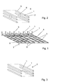
- the Lichtleitstäbe 1 are molded onto the intersections of a grid mat 4, which consists of intersecting and interconnected longitudinal and transverse bars 5, 6.
- the aforementioned longitudinal and transverse rods 5, 6 are also formed of a light-conducting plastic material, so that there is a very favorable light distribution to all arranged on the grid mat 4 Lichtleitstäbe 1, because the photoconductive longitudinal and transverse bars 5, 6 for a cheap and uniform Provide light distribution over the surface of the grid mat 4.
- the Leitleitstäbe be molded on the top and bottom of a plastic film or mat.
- FIG. 3 illustrated that the Lichtleitstäbe 1 any configuration, cross-sectional shape - which may thus be formed as disc or rectangular elements - are present in the form of a bundle 7, said bundle 7 by not shown spacer means the Lichtleitstäbe 1 in its intended configuration hold.
- an important advantage of the invention lies precisely in the fact that the assignment of the individual Lichtleitstäbe 1 can be done without fixing the spacing of the Lichtleitstäbe, as the FIG. 4 represents.
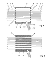
- a first formwork which consists of two mutually opposite formwork panels 8, 9, wherein the formwork panels 8, 9 of a plurality of holes 11 passes are, which are aligned with each other and through which the Lichtleitstäbe 1 are inserted.
- the formwork space is further closed by top and bottom side disposed cover plates 10 in itself.
- FIG. 6 Insulator 16 shown, in which now the Lichtleitstäbe 1 are safe to move and surrounded by all sides of the insulating material 15 surrounded.
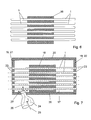
- At least the visible shuttering panel 18 is formed as a facade panel 21 and thus forms a permanent formwork for the shuttering space 17.
- the shuttering space 17 is further formed by the top and bottom side arranged cover plates 20, so that there is a total closed shuttering space 17.
- the rear formwork panel 19 of the after FIG. 7 produced multilayer composite molded body designed as a back facade panel 22.
- the material of the facade panel 21 disposed on the visible side coincides with the material of the facade panel 22 arranged on the rear side.
- FIG. 8 It is assumed that both the visible and the rear facade panel 21, 22 is present, so that the in FIG. 8 shown multilayer composite body results.
- FIG. 9 schematized shown in side view, where it can be seen that connects to the back of the visible facade panel 21 - which is also the formwork panel 18 - a first layer 28 of the rapidly curable potting compound 26 connects.
- This layer 28 forms an intimate bond to the front of the insulating body 16, and on the back of this insulating body 16, the second layer 29 of the curable, mechanically highly durable potting compound 26 molded and molded, and at the rear closes turn the rear facade panel 22 as lost Shuttering plate 19 on.
- the façade module 30 shown here does not necessarily consist of the layers 28, 16, 29. It can account for the layer 28, and the visible facade panel 21 can connect directly to the front of the insulating body 16.
- the back layer 29 is omitted and the rear facade panel 22 - if it is present - connects directly to the back of the insulating body 16.
- one or more light sources 31 irradiate the rear side of the rear facade panel 22, whereby the light is then received via the end faces of the light-conducting rods 1 engaging in the bores 23, guided along the longitudinal axis of the light-conducting rods 1 in the direction of the arrow 32 through the facade building block 30 and on the front side (visible side) brings the arranged in the visible facade panel 21 bores 23 lights up, because there fill the ends of the Lichtleitstäbe 1 as close as possible and flush with the holes 23.
- each Lichtleitstabes can still be provided with stepped projections 33 which engage centered in the holes 23, so as to ease mounting of the Lichtleitstäbe in the production of formwork according to FIG. 7 to enable.
- the stepped shoulder 33 forms rear abutment edges 34 on the light-conducting rod, with which the light-conducting rod rests against the rear side of the respective facade panel 21, 22.
- the heat-insulating layer 35 may also be designed in several parts or in multiple layers.
Abstract
Description
Die Erfindung betrifft ein Verfahren und eine Vorrichtung zur Herstellung eines lichtdurchlässigen Mehrschicht-Verbundbauelementes mit integrierter Fassadenplatte und ein nach dem Verfahren hergestelltes Mehrschicht-Verbundbauelement mit integrierter Fassadenplatte.The invention relates to a method and an apparatus for producing a translucent multi-layer composite component with integrated facade panel and a multilayer composite component with integrated facade panel produced by the method.
Ein eingangs genanntes Verfahren und eine Vorrichtung zur Herstellung eines derartigen lichtdurchlässigen Mehrschicht-Verbund-Bauelementes ist mit dem Gegenstand der
Bei der genannten Druckschrift wird das lichtdurchlässige Mehrschicht-Verbundbauelement dadurch hergestellt, dass zunächst die biegesteif ausgebildeten Lichtleitstäbe durch Bohrungen eines Isolierkörpers hindurch
gesteckt werden, so dass die mit ihren Enden aus den einander gegenüberliegenden Flächen der Isolierplatte hinausragen.In the cited document, the translucent multi-layer composite component is produced by first passing the flexurally configured light-conducting rods through holes in an insulating body
be plugged so that they protrude with their ends from the opposite surfaces of the insulating.
Der so hergestellte Grundkörper wird dann in eine Schalungsform eingetaucht, in deren Bodenfläche bereits schon eine aushärtbare Vergussmasse angeordnet ist, die als Tragschicht dient und die mechanisch belastbar ausgebildet ist.The base body thus produced is then immersed in a formwork, in the bottom surface already a curable potting compound is already arranged, which serves as a support layer and which is formed mechanically resilient.
Im nächsten Verfahrensschritt wird auf der Oberseite der Isolierplatte noch der Rest der aushärtbaren Vergussmasse aufgegossen, so dass sich damit ein an beiden Seiten mit einer Tragschicht abgeschlossener Mehrschicht-Verbundbaukörper ergibt. Wenn der so mit beidseitigen Tragschichten ausgegossene Mehrschicht-Verbundkörper aus der Schalung herausgenommen wird, ist als nächster Verfahrensschritt notwendig, die einander gegenüberliegenden Stirnseiten des Mehrschicht-Verbundkörpers zu beschleifen, um diese mit der Ebene der ausgehärteten Vorsatzschicht flächenbündig zu gestalten, um die Enden der Lichtleitstäbe frei zu legen.In the next process step, the remainder of the curable potting compound is poured onto the upper side of the insulating plate so that this results in a multilayer composite structure closed on both sides with a base layer. If the multi-layer composite body so poured out on both-sided support layers is taken out of the formwork, it is necessary as the next method step to grind the opposite end faces of the multilayer composite body, to make it flush with the plane of the cured facing layer to expose the ends of the Lichtleitstäbe.
Das geschilderte Herstellungsverfahren ist relativ aufwendig, weil zunächst in Handarbeit die Lichtleitstäbe durch Bohrungen eines Isolierstoffkörpers hindurch gesteckt werden müssen und als nächstes eine Schalungsform verwendet werden muss, in welcher die beiden einander gegenüberliegenden Vorsatzschichten auf dem Isolierkörper aufgegossen oder aufgespritzt werden.The described manufacturing process is relatively expensive, because first by hand, the Lichtleitstäbe must be inserted through holes in a Isolierstoffkörpers and next form a form must be used, in which the two opposing facing layers are poured or sprayed onto the insulating body.
Das nachfolgende Beschleifen der beiden einander gegenüberliegenden Stirnseiten erhöht den Arbeitsaufwand bei der Herstellung eines solchen Verbundkörpers erheblich.The subsequent grinding of the two opposite end faces increases the amount of work in the production of such a composite body considerably.
Nachteil des genannten Verfahrens ist nicht nur das relativ aufwendige Herstellungsverfahren, sondern darüber hinaus, dass es nicht möglich ist, den Mehrschicht-Verbundbaukörper mit einer Fassadenplatte zu verbinden.Disadvantage of the method mentioned is not only the relatively complicated manufacturing process, but beyond that it is not possible to connect the multi-layer composite structure with a facade panel.
Zwar wäre es möglich, eine Fassadenplatte mit Bohrungen direkt vor die Vorsatzschicht mit den stirnseitig dort verankerten Lichtleitstäben zu setzen, was jedoch mit dem Nachteil verbunden ist, dass es relativ schwierig ist, die Bohrungen in der Fassadeplatte fluchtend mit den in der Vorsatzschicht verankerten Stirnseiten der Lichtleitstäbe zur Deckung zu bringen. Außerdem ist die nachträgliche Verbindung einer Fassadenplatte mit der Vorsatzschicht nur schwierig über eine Klebung oder dergleichen auszuführen.Although it would be possible to put a facade panel with holes directly in front of the attachment layer with the front side there anchored Lichtleitstäben, but this is associated with the disadvantage that it is relatively difficult, the holes in the facade slab aligned with the anchored in the attachment layer end faces of To bring light guide rods to cover. In addition, the subsequent connection of a facade panel with the facing layer is difficult to perform on a bond or the like.
Ferner ist nachteilig, dass wegen der Dicke der Fassadenplatte von z. B. 2 bis 5 mm die Bohrungen in der vorgesetzten Fassadenplatte selbst nicht mit Lichtleitstäben ausgefüllt sind, sondern als Hohlbohrungen lediglich vor die Stirnseiten der Lichtleitstäbe vorgesetzt sind. Damit entsteht ein unerwünschter Lichtverlust, weil das Licht noch durch die Hohlbohrungen in den Fassadenplatten hindurch treten muss und hierbei Streuverluste erleidet. Ferner sind solche Hohlbohrungen in Fassadenplatten nachteilig, denn sie setzen sich mit Schmutz und Unrat voll, was bei einem längeren Gebrauch der Fassaden-Mehrschichtelemente zu einer vollständigen Abdeckung der lichtabgebenden Stirnseiten der Lichtleitelemente bedingt durch in den Bohrungen entstehende Ablagerungen führt.Furthermore, it is disadvantageous that because of the thickness of the facade panel of z. B. 2 to 5 mm, the holes in the superior facade panel itself are not filled with Lichtleitstäben, but are pre-set as hollow holes only in front of the end faces of the Lichtleitstäbe. This creates an undesirable loss of light, because the light still has to pass through the hollow holes in the facade panels and thereby suffers scattering losses. Furthermore, such hollow holes in facade panels are disadvantageous, because they are full of dirt and debris, resulting in a prolonged use of the facade multi-layer elements to a complete coverage of the light-emitting Front sides of the light guide leads due to deposits resulting in the holes.
Der Erfindung liegt deshalb die Aufgabe zugrunde, ein Verfahren und eine Vorrichtung zur Herstellung eines lichtdurchlässigen Mehrschicht-Verbundbauelementes so weiterzubilden, dass in das Mehrschicht-Verbundbauelement unmittelbar mindestens eine Fassadenplatte integriert werden kann und dass insgesamt das Herstellverfahren einfacher und kostengünstiger durchzuführen ist.The invention is therefore the object of developing a method and an apparatus for producing a translucent multilayer composite component so that in the multi-layer composite component directly at least one facade panel can be integrated and that overall the manufacturing process is easier and cheaper to perform.
Zur Lösung der gestellten Aufgabe ist die Erfindung durch die technische Lehre des Anspruches 1 gekennzeichnet.To solve the problem, the invention is characterized by the technical teaching of
Wesentliches Merkmal der Erfindung ist, dass mindestens auf einer Seite des erfindungsgemäßen Mehrschicht-Verbundbauelementes eine Fassadenplatte dadurch integriert ist, dass sie selbst als verlorenes Schalungselement und damit als Schalungsplatte an dem Mehrschicht-Verbund-Bauelement verbleibt, so dass damit ein Doppelnutzen erzielt wird.An essential feature of the invention is that at least on one side of the multilayer composite component according to the invention, a facade panel is integrated by itself as a lost formwork element and thus as a formwork panel on the multi-layer composite component remains, so that thus a double benefit is achieved.
Zum Einen wird die im zweiten Schritt verwendete Schalungsplatte erfindungsgemäß gleich als Fassadenplatte ausgebildet und verbleibt nach dem Ausschalen der Gieß- oder Spritzgussform am Bauelement selbst. Damit wird der Vorteil erreicht, dass die mit Bohrungen für den Eingriff der Stirnseiten der Lichtleitelemente ausgebildete Fassadenplatte die Lichtleitelemente bereits schon aufnimmt und die Bohrungen in der Fassadenplatte damit ausgefüllt sind, wodurch die vorher als nachteilig angesehenen Hohlbohrungen in der Fassadenplatte entfallen. Die Lichtleitelemente können an ihren Stirnseiten so flächenbündig in den Bohrungen oder Ausnehmungen der Schalungsplatte integriert werden, so dass diese flächenbündig mit der Außenseite der Schalungsplatte sind.On the one hand, the formwork panel used in the second step is inventively formed as a facade panel and remains after stripping the casting or injection mold on the component itself. Thus, the advantage is achieved that formed with holes for engagement of the end faces of the light guide facade panel already the light guide already absorbs and the holes in the facade panel are filled with it, which accounts for the previously considered disadvantageous hollow holes in the facade panel. The light-guiding elements can be integrated so as to be flush in the holes or recesses of the formwork panel at their end faces, so that they are flush with the outside of the formwork panel.
Weil die Schalungsplatte als Fassadenplatte ausgebildet ist, ergibt sich der Vorteil einer günstigen, haftschlüssigen Verbindung zwischen der als Schalungsplatte ausgebildeten Fassadenplatte und der daran angespritzten Vorsatzschicht oder Isolierschicht.Because the formwork panel is designed as a facade panel, there is the advantage of a cheap, adhesive connection between the formwork panel trained facade panel and the molded thereto attachment layer or insulating layer.
Zur Verbesserung des Haftverbundes kann es noch zusätzlich vorgesehen sein, dass an der Rückseite der Schalungsplatte (der späteren Fassadenplatte) noch zusätzliche Verankerungselemente angeformt sind, welche in die daran anzugießende oder zu spritzende Vorsatz- oder Isolierschicht eingreifen und dort verankert sind.To improve the adhesive bond, it may additionally be provided that on the back of the formwork panel (the later facade panel) additional anchoring elements are formed, which engage in the thereto zuzuschießende or to be sprayed intent or insulating layer and anchored there.
Der einfacheren Beschreibung wegen wird in der folgenden Beschreibung davon ausgegangen, dass das erfindungsgemäße Mehrschicht-Verbund-Bauelement an seinen entgegengesetzt zueinander liegenden Seiten (Sichtseite und Rückseite) jeweils mit als verlorene Schalungselementen ausgebildeten Fassadenplatten bedeckt ist, die jeweils am Mehrschicht-Verbund-Bauelement in der vorher beschriebenen Weise integriert sind.For the sake of simpler description, it is assumed in the following description that the multilayer composite component according to the invention is covered on its opposite sides (visible side and rear side) with façade panels designed as permanent shuttering elements, in each case on the multilayer composite component in FIG integrated as previously described.
In einer demgegenüber vereinfachten Ausführungsform kann es jedoch vorgesehen sein, dass die die Rückseite des Mehrschicht-Verbund-Bauelementes bildende Fassadenplatte nicht aus dem gleichen Material besteht wie die die Sichtseite des Verbund-Bauelementes bildende vordere Fassadenplatte. Es kann hierbei vorgesehen sein, dass die die Rückseite ausbildende Platte, z. B. aus einem Holzwerkstoff, einem kostengünstigen Kunststoffwerkstoff, aus Papier oder Pappe besteht, wobei nur wesentlich ist, dass die die Rückseite des Verbundbauelementes ausbildende Schalungsplatte (genauso wie die auf der Vorderseite angeordnete Fassadenplatte) dem Schalungsdruck der in die Schalung einfließenden Vergussmasse standhalten kann.However, in a simplified embodiment on the other hand, it may be provided that the facade panel forming the rear side of the multi-layer composite component is not made of the same material as the front facade panel forming the visible side of the composite component. It can be provided here that the rear side forming plate, z. B. from a wood material, a low cost plastic material, made of paper or cardboard, is only essential that the back of the composite component forming formwork panel (as well as arranged on the front panel) can withstand the formwork pressure of the casting compound flowing into the formwork.
Es kann sogar in einer Weiterbildung der Erfindung vorgesehen sein, dass nach dem Aushärten der Vergussmasse an der Rückseite des Mehrschicht-Verbundkörpers die rückseitige Schalungsplatte entfernt wird, so dass das erfindungsgemäße Mehrschicht-Verbund-Bauelement nur mit einer sichtseitigen Fassadenplatte integriert ist, während an der Rückseite die Schalungsplatte entfernt wurde.It may even be provided in a development of the invention that after curing of the potting compound on the back of the multilayer composite body, the back side shuttering plate is removed, so that the multilayer composite element according to the invention is integrated only with a visible facade panel, while at the Rear of the formwork panel was removed.
Die Erfindung beansprucht deshalb ein Mehrschicht-Verbund-Bauelement, welches mindestens an seiner Sichtseite eine mit Bohrungen versehene Fassadenplatte aufweist, in welche Bohrungen die lichtleitenden Enden der Lichtleitstäbe oder Lichtleitelemente aufgenommen sind.The invention therefore claims a multilayer composite component which has at least on its visible side a facade plate provided with bores into which holes the light-conducting ends of the light-conducting rods or light-guiding elements are accommodated.
Unter dem in den Patentansprüchen verwendeten Begriff "Lichtleitelemente" werden sämtliche biegesteifen Lichtleitelemente verstanden, wie z. B. Lichtleitstäbe mit rundem, eckigem, ovalem oder quadratischem Querschnitt, ebenso wie stabförmige, scheibenförmige oder andere Lichtleitelemente, die bevorzugt aus einem lichtleitenden Kunststoff hergestellt sind.Under the term "light-guiding elements" used in the claims are understood to mean all rigid light-guiding elements, such. B. Lichtleitstäbe with round, square, oval or square cross-section, as well as rod-shaped, disc-shaped or other light-guiding elements, which are preferably made of a photoconductive plastic.
Der einfacheren Beschreibung wegen wird deshalb in der folgenden Beschreibung die spezielle Ausführungsform eines Lichtleitelementes näher beschrieben, nämlich die Ausbildung als Lichtleitstab, obwohl die Erfindung nicht darauf beschränkt ist.For the sake of simplicity of description, therefore, in the following description, the specific embodiment of a light guiding element will be described in more detail, namely, the embodiment as a light guiding rod, although the invention is not limited thereto.
Ebenso sieht die Erfindung verschiedene Möglichkeiten der Anordnung von Lichtleitstäben vor, wobei in einer ersten Ausführungsform vorgesehen sein kann, dass die Lichtleitstäbe im Spritzgussverfahren an einer Gitterstabmatte angespritzt sind, wobei die Gitterstabmatte selbst ebenfalls aus einem lichtleitenden Kunststoff besteht. Somit sind die Längs- und Querstäbe der Lichtleitermatte aus einem lichtleitenden Material ausgebildet, und in den Kreuzungspunkten der Längs- und Querstäbe sind die senkrecht davon abragenden Lichtleitstäbe angespritzt.Likewise, the invention provides various possibilities for the arrangement of Lichtleitstäben, which may be provided in a first embodiment that the Lichtleitstäbe are injection-molded on a grid bar mat, wherein the grid bar mat itself also consists of a photoconductive plastic. Thus, the longitudinal and transverse rods of the optical fiber mat are formed of a light-conducting material, and in the crossing points of the longitudinal and transverse rods perpendicular projecting therefrom Lichtleitstäbe are molded.
Die Lichtleitstäbe überragen somit mit ihren oberen Enden die Gittermatte nach oben und mit ihren unteren Enden die Gittermatte nach unten, so dass sich ein dreidimensionales Gebilde ergibt.The Lichtleitstäbe thus project beyond the grid mat with their upper ends up and with their lower ends, the grid mat down, so that there is a three-dimensional structure.
In einer vereinfachten Ausführungsform kann es jedoch auch vorgesehen sein, dass die Lichtleitstäbe als Bündel ausgebildet sind, d. h. sie haben keine Fixierung oder Bindung zueinander, sondern werden erst durch Eingießen in einen Isolierkörper fixiert und erhalten dort ihre gewünschte Raumanordnung.In a simplified embodiment, however, it may also be provided that the Lichtleitstäbe are formed as a bundle, ie they have no fixation or bond to each other, but are first fixed by pouring into an insulating and there receive their desired spatial arrangement.
In einer dritten Ausgestaltung kann es vorgesehen sein, dass die einzelnen Lichtleitstäbe durch andere Fixierungselemente (vorläufig vor Durchführung des Giess- oder Spitzprozesses) zueinander auf Abstand gehalten werden, wie z. B. durch ein Textilgewebe, durch elastomere Massen und dergleichen mehr, wobei die so hergestellte Raumfixierung der Lichtleitstäbe nur für eine vorläufige Fixierung der Lichtleitstäbe dienen soll und nur bis zu dem Zeitpunkt, bis zu dem die mit der Fixierung versehenen Lichtleitstäbe als Bündel in die erste Schalungsform eingelegt werden und dann im Mittenbereich mit einem Isolierstoff ausgespritzt werden.In a third embodiment, it may be provided that the individual Lichtleitstäbe be held by other fixing elements (provisionally before performing the casting or pointed process) to each other at a distance, such. B. by a textile fabric, by elastomeric masses and the like more, wherein the space fixation of the Lichtleitstäbe thus produced should only serve for a provisional fixation of the Lichtleitstäbe and only until the time to which provided with the fixing Lichtleitstäbe as a bundle in the first Form form are inserted and then injected in the middle area with an insulating material.
Damit wird ein etwa mittiger Isolierkörper hergestellt, der bevorzugt aus einem wärmedämmenden Material besteht (z. B. Polyurethanschaum). Sobald die Lichtleitstäbe mit ihrer vorläufigen Fixierung im ausgehärteten Isolierkörper fixiert sind, kommt es auf eine weitere Lagensicherung der Lichtleitstäbe nicht mehr an. Der aus einem aushärtbaren Wärmedämmstoff bestehende Isolierkörper übernimmt dann die Lagenfixierung der Lichtleitstäbe.This produces an approximately central insulating body which preferably consists of a heat-insulating material (eg polyurethane foam). Once the Lichtleitstäbe are fixed with their provisional fixation in cured insulator, it depends on a further position assurance of the light-conducting rods no longer. The existing of a thermosetting insulating insulating body then assumes the position fixation of Lichtleitstäbe.
Das Material der die Vorsatzschicht oder Tragschicht bildenden Vergussmasse besteht bevorzugt aus einer aushärtbaren Betonschicht, die bevorzugt aus einem selbstverdichtenden Beton (SCC- Self Compacting Concrete) besteht.The material of the facing layer or base layer forming potting compound is preferably made of a hardenable concrete layer, which preferably consists of a self-compacting concrete (SCC Self Compacting Concrete).
Statt eines solchen SCC-Materials kommen auch noch andere aushärtbare Massen in Betracht, wie z. B. gießfähige und aushärtbare Holzverbundwerkstoffe, Kunststoffe, Kunststoff-Mineralgemische, Mineralgussmassen, Tone, Kalke und dergleichen aushärtbare Massen mehr.Instead of such an SCC material are also other curable materials into consideration, such as. As pourable and thermosetting wood composites, plastics, plastic mineral mixtures, mineral casting compounds, clays, limestones and the like curable masses more.
Wichtig ist, dass die die Vorsatzschicht bildende Vergussmasse eine relativ hohe mechanische Tragfähigkeit aufweist, so dass ein damit hergestellter Mehrschicht-Verbund-Baustein unmittelbar als Fassadenbaustein (z.B. in der Form als Ziegelstein) in einen Baukörper integriert werden kann und der gegenseitige Verbund zwischen den Bausteinen durch Beton oder einen aushärtbaren Kunststoff oder mechanische Verbindungsanker erfolgt.It is important that the potting compound forming the facing layer has a relatively high mechanical load-bearing capacity, so that a multi-layer composite building block produced therewith can be integrated directly into a building as a façade building block (eg in the form of a brick) and the mutual bond between the building blocks done by concrete or a hardenable plastic or mechanical connection anchor.
Die bevorzugt aus dem gießfähigen und aushärtbaren Beton bestehende Vergussmasse unterscheidet sich von dem aushärtbaren Isolierstoff durch eine höhere Tragfähigkeit, jedoch durch eine geringere Wärmedämmfähigkeit.The preferred from the pourable and hardenable concrete existing potting compound differs from the curable insulating material by a higher load capacity, but by a lower thermal insulation capability.
Die Erfindung ist jedoch nicht auf einen dreischichtigen Kern des Mehrschicht-Verbund-Bauelementes beschränkt.However, the invention is not limited to a three-layer core of the multilayer composite device.
In der ersten beschriebenen Ausführungsform besteht dieser Kern aus einer direkt hinter der sichtseitigen Fassadenplatte angeordneten Schicht aus der mechanisch hoch belastbaren Vergussmasse, an die sich ein etwa mittlerer Isolierkörper aus einem hochwärmedämmenden Isolierstoff anschließt, an dessen Rückseite wiederum die zweite hochbelastbare Vergussmasse die weitere Schicht bildet, die nun wieder rückseitig durch eine weitere Fassadenplatte oder durch eine andere Abdeckplatte oder Schalplatte abgedeckt ist, die - entsprechend der vorstehenden Beschreibung - auch nach dem Vergießen der rückseitigen Vergussmasse entfernt werden kann.In the first described embodiment, this core consists of a directly behind the visible facade panel layer arranged from the mechanically highly durable potting compound, which is followed by an approximately average insulator made of a highly insulating insulating material, on the back in turn the second heavy-duty potting compound forms the further layer, which is now back covered by a further facade panel or by another cover plate or formwork panel, which - according to the above description - can be removed even after the casting of the back casting compound.
Die Erfindung sieht auch eine Ausführung vor, bei der die nächst der Sichtseite direkt hinter der sichtseitigen Fassadenplatte angeordnete hochbelastbare Vergussmasse entfällt und stattdessen die Fassadenplatte direkt mit ihrer Rückseite an der Vorderseite des Isolierkörpers anschließt und dort verankert ist.The invention also provides an embodiment in which the next visible side disposed behind the visible side facade panel heavy-duty potting omitted and instead connects the facade panel directly with its back on the front of the insulator and anchored there.
Es kann ebenso vorgesehen sein, dass auch deck- und bodenseitig weitere Schichten aus einer hochbelastbaren Vergussmasse oder einer wärmedämmenden Isolierstoffmasse angeordnet sind, deren Anordnung mit einer oder mehreren der vorher genannten Ausführungen korrespondiert.It may also be provided that also cover and bottom side further layers of a highly durable potting compound or a heat-insulating material are arranged, the arrangement corresponds to one or more of the aforementioned embodiments.
Wichtig bei der Erfindung ist jedenfalls, dass die Fassadenplatte eine wärmedämmende Schicht enthält, wobei - wie ausgeführt - die nächst der sichtseitigen Fassadenplatte angeordnete hochbelastbare Vergussmasse auch entfallen kann.Important in the invention is in any case that the facade panel includes a heat-insulating layer, wherein - as stated - the next of the visible facade panel arranged heavy-duty potting compound can also be omitted.
Ebenso kann auch die an der Rückseite des Isolierkörpers angeordnete Vergussmasse entfallen, und die rückseitig angeordnete Schalplatte oder Fassadenplatte kann unmittelbar an den Isolierkörper anschließen und in diesem verankert sein.Likewise, the potting compound arranged on the rear side of the insulating body may also be dispensed with, and the rear-side molded panel or Facade panel can connect directly to the insulator and anchored in this.
Als Fassadenplatte werden bevorzugt aus einer Leichtmetalllegierung bestehende Metallplatten verwendet. Es können jedoch auch andere Plattenarten verwendet werden, wie z. B. Kunststoffplatten oder mit Folien belegte Kunststoff- oder Metall- oder Holzplatten.As a façade panel consisting of a light metal alloy metal plates are preferably used. However, other types of plates can be used, such. As plastic sheets or coated with films plastic or metal or wood panels.
Wichtig ist, dass die sichtseitig angeordnete Fassadenplatte auch gleichzeitig die Sichtseite des Bauwerkes bildet und damit ein dekoratives Äußeres ausbilden soll.It is important that the façade panel arranged on the visible side simultaneously forms the visible side of the building and thus forms a decorative appearance.
Zur Erzielung dieses Zweckes kann es vorgesehen sein, dass die Aluminiumplatte noch mit Dekorationsfolien belegt ist, einen Druck trägt oder Kunststoff-Metallverbundplatten verwendet werden.To achieve this purpose, it may be provided that the aluminum plate is still covered with decorative films, bears a pressure or plastic-metal composite plates are used.
Vorteilhaft bei der Ausführung des Verfahrens ist nämlich, dass es keiner Versäuberung der Sichtseite der sichtseitigen Fassadenplatte bedarf, weil diese als verlorene Schalung sauber mit ihrer Außenseite (der späteren Sichtseite) in die Schalung eingelegt wird und dort keinen Schmutzeinflüssen ausgesetzt ist. Lediglich an die Rückseite dieser sichtseitigen Fassadenplatte wird die Vergussmasse oder wahlweise der Isolierkörper angespritzt oder angeformt oder verankert, was die Vorderseite dieser Fassadenplatte nicht beeinträchtigt.An advantage of the embodiment of the method is namely that it does not require Versäuberung the visible side of the visible facade panel because it is placed as a lost formwork clean with its outside (the later visible side) in the formwork and there is exposed to any dirt. Only at the back of this visible facade panel, the potting compound or optionally the insulating body is molded or molded or anchored, which does not affect the front of this facade panel.
Es bedarf daher keiner aufwendigen Versäuberung der Sichtseite der Fassadenplatte und auch nicht einer Freilegung der flächenbündig bereits dort in die Bohrungen eingreifenden Lichtleitstäbe oder in die dort angeordneten Ausnehmungen eingreifenden Lichtleitelemente.Therefore, there is no need for elaborate Versäuberung the visible side of the facade panel and also not an exposure of the flush-fitting already there in the holes engaging Lichtleitstäbe or in the recesses arranged there intervening light-guiding elements.
Der Erfindungsgegenstand der vorliegenden Erfindung ergibt sich nicht nur aus dem Gegenstand der einzelnen Patentansprüche, sondern auch aus der Kombination der einzelnen Patentansprüche untereinander.The subject of the present invention results not only from the subject matter of the individual claims, but also from the combination of the individual claims with each other.
Alle in den Unterlagen, einschließlich der Zusammenfassung offenbarten Angaben und Merkmale, insbesondere die in den Zeichnungen dargestellte räumliche Ausbildung, werden als erfindungswesentlich beansprucht, soweit sie einzeln oder in Kombination gegenüber dem Stand der Technik neu sind.All information and features disclosed in the documents, including the abstract, in particular the spatial ones shown in the drawings Training, are claimed as essential to the invention, as far as they are new individually or in combination over the prior art.
Im Folgenden wird die Erfindung anhand von mehrere Ausführungswege darstellenden Zeichnungen näher erläutert. Hierbei gehen aus den Zeichnungen und ihrer Beschreibung weitere erfindungswesentliche Merkmale und Vorteile der Erfindung hervor.In the following, the invention will be explained in more detail with reference to drawings illustrating several execution paths. Here are from the drawings and their description further features essential to the invention and advantages of the invention.
Es zeigen:
- Figur 1:
- in perspektivischer Darstellung eine Lichtleitermatte
- Figur 2:
- schematisiert einen vergrößerten Ausschnitt aus
Figur 1 mit um 90° gedrehten Lichtleitstäben - Figur 3:
- ein Bündel aus Lichtleitstäben, deren gegenseitiger Abstand nicht fixiert ist
- Figur 4:
- der erste Verfahrensschritt zur Herstellung des inneren Isolierkörpers vor Einspritzen des Isolierstoffes in den Schalungsraum
- Figur 5:
- die gleiche
Darstellung wie Figur 4 nach dem Einspritzen des Isolierstoffes - Figur 6:
- die
Darstellung nach Figur 5 nach Entfernung der endseitig angeordneten Schalungsplatten - Figur 7:
- der sich aus
Figur 6 ergebende Körper bei Einbringung in einen zweiten Schalungsraum mit Anordnung von Fassadenplatten als endseitige Schalungsplatten vor dem Einspritzen einer Vergussmasse - Figur 8:
- der sich aus
Figur 7 ergebende fertig gestellte Mehrschicht-VerbundBaukörper - Figur 9:
- der Baukörper nach
Figur 8 in perspektivischer Seitenansicht - Figur 10:
- schematisiert das endseitige Eingreifen der Lichtleitstäbe in die Bohrungen der sichtseitigen Fassadenplatte
- FIG. 1:
- in perspective view a light guide mat
- FIG. 2:
- schematizes an enlarged section
FIG. 1 with light guide rods rotated by 90 ° - FIG. 3:
- a bundle of Lichtleitstäben whose mutual distance is not fixed
- FIG. 4:
- the first method step for producing the inner insulating body before injection of the insulating material in the formwork space
- FIG. 5:
- the same representation as
FIG. 4 after injecting the insulating material - FIG. 6:
- the representation after
FIG. 5 after removal of the shuttering plates arranged at the end - FIG. 7:
- that turns out
FIG. 6 resulting body when introduced into a second formwork space with arrangement of facade panels as end shuttering panels prior to the injection of a potting compound - FIG. 8:
- that turns out
FIG. 7 resulting finished multi-layer composite building bodies - FIG. 9:
- the building after
FIG. 8 in perspective side view - FIG. 10:
- schematizes the end-side engagement of the Lichtleitstäbe in the holes of the visible facade panel
In den
Im gezeigten Ausführungsbeispiel besteht jeder Lichtleitstab aus einem lichtleitenden Kunststoffmaterial, wie z. B. Polykarbon oder dergleichen. Jeder Lichtleitstab 1 weist ein oberes Ende 2 und ein unteres Ende 3 auf und kann eine beliebige Profilierung aufweisen.In the illustrated embodiment, each Lichtleitstab of a photoconductive plastic material such. As polycarbonate or the like. Each
Im gezeigten Ausführungsbeispiel nach
Die genannten Längs- und Querstäbe 5, 6 sind ebenfalls aus einem lichtleitenden Kunststoffmaterial ausgebildet, so dass sich eine sehr günstige Lichtverteilung auf alle an der Gittermatte 4 angeordneten Lichtleitstäbe 1 ergibt, weil die lichtleitenden Längs- und Querstäbe 5, 6 für eine günstige und gleichmäßige Lichtverteilung über die Fläche der Gittermatte 4 sorgen. Ebenso können die Leitleitstäbe auf der Ober- und Unterseite einer aus Kunststoff bestehenden Folie oder Matte angespritzt sein.The aforementioned longitudinal and
Als anderes Ausführungsbeispiel ist in
Ein wichtiger Vorteil der Erfindung liegt nun aber gerade darin, dass die Zuordnung der einzelnen Lichtleitstäbe 1 ohne Fixierungsmittel für die Abstandhaltung der Lichtleitstäbe erfolgen kann, wie dies die
Um nämlich die Lichtleitstäbe 1, die keinerlei Fixierungsmittel aufweisen, in einer bestimmten gewünschten Konfiguration abstandshaltend zu verbinden, ist eine erste Schalungsform vorgesehen, die aus zwei einander gegenüberliegenden Schalungsplatten 8, 9 besteht, wobei die Schalungsplatten 8, 9 von einer Vielzahl von Bohrungen 11 durchsetzt sind, die zueinander fluchten und durch welche die Lichtleitstäbe 1 gesteckt sind.Namely, in order to connect the
Entsprechend der Art und Anordnung der Bohrung 11 werden somit die Lichtleitstäbe 1 von Hand oder maschinell in die Bohrungen 11 der Schalungsplatten 8, 9 eingesteckt, bis sie die in
Der Schalungsraum wird ferner noch durch ober- und unterseitig angeordnete Deckplatten 10 in sich geschlossen.The formwork space is further closed by top and bottom side disposed
In den Schalungsraum wird gemäß
Nach Entfernung der Schalungsplatten 9 und der deck- und bodenseitig angeordneten Platten 10 ergibt sich der in
Hierdurch sind alle Lichtleitstäbe 1 fixiert, und es bedarf keiner weiteren abstandshaltenden Fixierelemente oder dergleichen, um den so nach
Wichtig ist nun, dass zur Herstellung der Schalung nach
Erfindungsgemäß ist nun vorgesehen, dass mindestens die sichtseitige Schalungsplatte 18 als Fassadenplatte 21 ausgebildet ist und somit eine verlorene Schalung für den Schalungsraum 17 ausbildet.According to the invention it is now provided that at least the visible shuttering panel 18 is formed as a facade panel 21 and thus forms a permanent formwork for the shuttering
Der Schalungsraum 17 wird ferner gebildet durch die boden- und deckseitig angeordneten Deckplatten 20, so dass sich ein insgesamt abgeschlossener Schalungsraum 17 ergibt.The shuttering
Wenn nun beim Einfüllen einer aushärtenden Vergussmasse 26 in Pfeilrichtung 25 über eine geeignete Füllvorrichtung 24 die relativ schwergewichtige Vergussmasse in den Schalungsraum 17 einfließt, sind die Lichtleitstäbe 1 gegen den hierdurch entstehenden Verformungsdruck in ausgezeichneter Weise fixiert, denn sie sind mit ihren Endseiten jeweils in den Bohrungen 23 der Schalungsplatten 18, 19 aufgenommen und können sich nicht verschieben oder verbiegen.Now, when the filling of a curing
In einer ersten Ausführungsform der Erfindung ist auch die rückseitige Schalungsplatte 19 des nach
Hierbei ist es nicht lösungsnotwendig, dass das Material der sichtseitig angeordneten Fassadenplatte 21 mit dem Material der rückseitig angeordneten Fassadenplatte 22 übereinstimmt.In this case, it is not necessary for the solution that the material of the facade panel 21 disposed on the visible side coincides with the material of the facade panel 22 arranged on the rear side.
Es wurde im allgemeinen Beschreibungsteil darauf hingewiesen, dass nach dem Ausgießen des Schalungsraumes 17 auch die rückseitige Schalungsplatte 19 vollkommen entfernt werden kann, so dass die hieraus gebildete Fassadenplatte 22 fehlen kann.It has been pointed out in the general description part that after pouring out the
Im gezeigten, einfacheren Ausführungsbeispiel wird jedoch gemäß
Dieser ist in
Diese Schicht 28 bildet einen innigen Verbund zur Vorderseite des Isolierkörpers 16, und an der Rückseite dieses Isolierkörpers 16 ist die zweite Schicht 29 aus der aushärtbaren, mechanisch hoch belastbaren Vergussmasse 26 angespritzt und angeformt, und an deren Rückseite schließt wiederum die rückseitige Fassadenplatte 22 als verlorene Schalungsplatte 19 an.This
Wie bereits im allgemeinen Beschreibungsteil darauf hingewiesen, muss der hier gezeigte Fassadenbaustein 30 nicht unbedingt aus den Schichten 28, 16, 29 bestehen. Es kann die Schicht 28 entfallen, und die sichtseitige Fassadenplatte 21 kann direkt an die Vorderseite des Isolierkörpers 16 anschließen.As already pointed out in the general part of the description, the
Ebenso kann in einer anderen Ausgestaltung vorgesehen sein, dass die rückseitige Schicht 29 entfällt und die rückseitige Fassadenplatte 22 - sofern sie vorhanden ist - direkt an die Rückseite des Isolierkörpers 16 anschließt.Likewise, it may be provided in another embodiment that the
In
In
Der Stufenansatz 33 bildet rückseitige Anschlagkanten 34 am Lichtleitstab aus, mit dem sich der Lichtleitstab an der Rückseite der jeweiligen Fassadenplatte 21, 22 anlegt.The stepped
Die wärmedämmende Schicht 35 kann auch mehrteilig oder mehrschichtig ausgebildet sein.The heat-insulating layer 35 may also be designed in several parts or in multiple layers.
- 11
- LichtleiterstabLight pipe
- 22
- oberes Endetop end
- 33
- unteres Endelower end
- 44
- Gittermattegrid mat
- 55
- Längsstablongitudinal bar
- 66
- Querstabcross bar
- 77
- Bündelbunch
- 88th
- Schalungsplatteshuttering panel
- 99
- Schalungsplatteshuttering panel
- 1010
- Deckplattecover plate
- 1111
- Bohrungdrilling
- 1212
- Schalungsraumformwork space
- 1313
- Füllvorrichtungfilling
- 1414
- Pfeilrichtungarrow
- 1515
- Isolierstoffinsulator
- 1616
- Isolierkörperinsulator
- 1717
- Schalungsraumformwork space
- 1818
- Schalungsplatteshuttering panel
- 1919
- Schalungsplatteshuttering panel
- 2020
- Deckplattecover plate
- 2121
- Fassadenplattefacade panel
- 2222
- Fassadenplattefacade panel
- 2323
- Bohrungdrilling
- 2424
- Füllvorrichtungfilling
- 2525
- Pfeilrichtungarrow
- 2626
- Vergussmassepotting compound
- 2727
- Pfeilrichtungarrow
- 2828
- Schicht (aus 26)Layer (from 26)
- 2929
- Schicht (aus 26)Layer (from 26)
- 3030
- Fassadenbausteinfacade building block
- 3131
- Lichtquellelight source
- 3232
- Pfeilrichtungarrow
- 3333
- Stufenansatzstage approach
- 3434
- Anschlagkantestop edge
- 3535
- Schicht (aus 16)Layer (from 16)
Claims (8)
b1.) die im zweiten Schritt verwendeten Schalungsplatten (18, 19) als verlorene Schalungselemente aus mit Bohrungen (23) oder Ausnehmungen versehenen Fassadenplatten (21, 22) gebildet sind, in welchen die Stirnseiten der Lichtleitelemente (1) mindestens teilweise aufgenommen sind.A method for producing a heat-insulated, multilayer composite light-conducting component for building facades and the like, in which the multilayer composite component comprises at least one layer (28, 29) of a hardenable potting compound (26) and at least one thermally insulated layer ( 35) consists of an insulating material (15), and all layers (28, 29, 35) of light-conducting elements (1) are interspersed, wherein
b1.) the shuttering panels (18, 19) used in the second step are formed as permanent formwork elements from facade panels (21, 22) provided with bores (23) or recesses, in which the end faces of the light guide elements (1) are at least partially accommodated.
Applications Claiming Priority (1)
| Application Number | Priority Date | Filing Date | Title |
|---|---|---|---|
| DE102011111318A DE102011111318A1 (en) | 2011-08-26 | 2011-08-26 | Method and device for producing a translucent multi-layer composite component with integrated facade panel |
Publications (3)
| Publication Number | Publication Date |
|---|---|
| EP2559532A2 true EP2559532A2 (en) | 2013-02-20 |
| EP2559532A3 EP2559532A3 (en) | 2014-05-28 |
| EP2559532B1 EP2559532B1 (en) | 2017-04-26 |
Family
ID=46603509
Family Applications (1)
| Application Number | Title | Priority Date | Filing Date |
|---|---|---|---|
| EP12005398.8A Not-in-force EP2559532B1 (en) | 2011-08-26 | 2012-07-25 | Method for producing a translucent multilayer composite building element with integrated façade panel, and products produced thereby |
Country Status (7)
| Country | Link |
|---|---|
| US (1) | US9211653B2 (en) |
| EP (1) | EP2559532B1 (en) |
| CN (1) | CN102953499B (en) |
| AU (1) | AU2012216408B2 (en) |
| CA (1) | CA2786395C (en) |
| DE (1) | DE102011111318A1 (en) |
| RU (1) | RU2599817C2 (en) |
Cited By (3)
| Publication number | Priority date | Publication date | Assignee | Title |
|---|---|---|---|---|
| EP2868826A1 (en) * | 2013-10-31 | 2015-05-06 | Basf Se | Concrete element containing an acoustic absorber |
| US9580356B2 (en) | 2013-10-31 | 2017-02-28 | Construction Research & Technology, Gmbh | Self-foaming geopolymer composition containing aluminum dross |
| US10214452B2 (en) | 2013-10-31 | 2019-02-26 | Construction Research & Technology, Gmbh | Geopolymer foam formulation for a non-flammable, sound-absorbing, thermally insulating geopolymer foam element |
Families Citing this family (10)
| Publication number | Priority date | Publication date | Assignee | Title |
|---|---|---|---|---|
| DE102014219261A1 (en) * | 2014-09-24 | 2016-03-24 | August Mink Kg | Support plate for a production of a transparent component and method for producing a transparent component and use of a support plate |
| US10906204B2 (en) * | 2015-05-19 | 2021-02-02 | Zospeum Holding B.V | Translucent building element and method of manufacturing same |
| IT201700054669A1 (en) * | 2017-05-19 | 2018-11-19 | Italcementi Spa | METHOD FOR THE REALIZATION OF A COMPOSITE PANEL, PREFERABLY BASED ON CEMENT MORTAR, WITH PROPERTIES OF TRANSPARENCY IN LIGHT |
| RU176734U1 (en) * | 2017-06-08 | 2018-01-25 | Андрей Владимирович Шишкин | LIGHT-PANEL DECORATIVE PANEL |
| RU176901U1 (en) * | 2017-07-27 | 2018-02-01 | Антон Сергеевич Доренский | LIGHT CONDUCTING ELEMENT |
| DE102017117820A1 (en) * | 2017-08-07 | 2019-02-07 | Dieter Christandl | Method for producing a curable, plate-shaped light body, tool for carrying out the method and light guide body produced by the method |
| CN108360739A (en) * | 2018-04-26 | 2018-08-03 | 南京工业大学 | A kind of efficiency translucent concrete plate |
| DE102018207761B3 (en) * | 2018-05-17 | 2019-09-26 | Polycare Research Technology Gmbh & Co. Kg | Segment for a building, process for its production, building and process for its production |
| CN108858736B (en) * | 2018-06-06 | 2020-08-14 | 南京工业大学 | Rapid forming method for semitransparent concrete plate |
| CN109093838B (en) * | 2018-09-14 | 2021-01-29 | 深圳市固亿建材水泥制品有限公司 | Printing opacity concrete slab |
Citations (1)
| Publication number | Priority date | Publication date | Assignee | Title |
|---|---|---|---|---|
| EP1970179A2 (en) | 2007-03-15 | 2008-09-17 | DelunaMagma Industries GmbH | Method and device for producing a translucent multilayer composite component for facades |
Family Cites Families (10)
| Publication number | Priority date | Publication date | Assignee | Title |
|---|---|---|---|---|
| JPH0727292Y2 (en) * | 1990-04-11 | 1995-06-21 | 三和産業株式会社 | Three-dimensional structure with embedded optical fiber |
| RU2143039C1 (en) * | 1998-04-13 | 1999-12-20 | Писаревский Иван Федорович | Construction lighting panel |
| SE522171C2 (en) * | 2002-05-17 | 2004-01-20 | Aron Losonczi | Building blocks comprising light-permeable fibers and method of making the same |
| JP4353105B2 (en) * | 2005-02-10 | 2009-10-28 | 株式会社大林組 | Method for manufacturing light transmissive member |
| CN100430333C (en) * | 2005-09-29 | 2008-11-05 | 润弘精密工程事业股份有限公司 | Concrete building material with light peneration and its production |
| HU226967B1 (en) * | 2007-07-11 | 2010-03-29 | Aron Losonczi | Light transmitting building block, manufacturing method for the same and lining element |
| EP2177332A1 (en) * | 2008-09-25 | 2010-04-21 | Jürgen Frei | Light-conducting component with thermal isolation |
| IT1394519B1 (en) * | 2008-12-11 | 2012-07-05 | Italcementi Spa | COMPOSITE PANEL BASED ON CEMENTITIOUS MORTAR WITH TRANSPARENCY PROPERTIES |
| IT1401450B1 (en) * | 2010-06-10 | 2013-07-26 | Italcementi Spa | COMPOSITE PANEL PERFECTED BASED ON CEMENT MORTAR WITH TRANSPARENT PRIORITY |
| CN101906836B (en) * | 2010-07-28 | 2011-10-26 | 湖南科技大学 | Non-light tight concrete member and manufacturing method thereof |
-
2011
- 2011-08-26 DE DE102011111318A patent/DE102011111318A1/en not_active Ceased
-
2012
- 2012-07-25 EP EP12005398.8A patent/EP2559532B1/en not_active Not-in-force
- 2012-07-27 US US13/559,775 patent/US9211653B2/en not_active Expired - Fee Related
- 2012-08-17 CA CA2786395A patent/CA2786395C/en not_active Expired - Fee Related
- 2012-08-23 AU AU2012216408A patent/AU2012216408B2/en not_active Ceased
- 2012-08-24 RU RU2012136432/03A patent/RU2599817C2/en active
- 2012-08-24 CN CN201210307168.8A patent/CN102953499B/en not_active Expired - Fee Related
Patent Citations (1)
| Publication number | Priority date | Publication date | Assignee | Title |
|---|---|---|---|---|
| EP1970179A2 (en) | 2007-03-15 | 2008-09-17 | DelunaMagma Industries GmbH | Method and device for producing a translucent multilayer composite component for facades |
Cited By (6)
| Publication number | Priority date | Publication date | Assignee | Title |
|---|---|---|---|---|
| EP2868826A1 (en) * | 2013-10-31 | 2015-05-06 | Basf Se | Concrete element containing an acoustic absorber |
| WO2015063022A1 (en) * | 2013-10-31 | 2015-05-07 | Construction Research & Technology Gmbh | Concrete element comprising a sound-absorber |
| US9580356B2 (en) | 2013-10-31 | 2017-02-28 | Construction Research & Technology, Gmbh | Self-foaming geopolymer composition containing aluminum dross |
| US10017938B2 (en) | 2013-10-31 | 2018-07-10 | Construction Research & Technology, Gmbh | Concrete element comprising a sound-absorber |
| US10214452B2 (en) | 2013-10-31 | 2019-02-26 | Construction Research & Technology, Gmbh | Geopolymer foam formulation for a non-flammable, sound-absorbing, thermally insulating geopolymer foam element |
| US10597326B2 (en) | 2013-10-31 | 2020-03-24 | Construction Research & Technology, Gmbh | Geopolymer foam formulation for a non-flammable, sound-absorbing, thermally insulating geopolymer foam element |
Also Published As
| Publication number | Publication date |
|---|---|
| AU2012216408B2 (en) | 2017-07-27 |
| US20140030479A1 (en) | 2014-01-30 |
| DE102011111318A1 (en) | 2013-02-28 |
| EP2559532B1 (en) | 2017-04-26 |
| EP2559532A3 (en) | 2014-05-28 |
| CN102953499A (en) | 2013-03-06 |
| RU2012136432A (en) | 2014-02-27 |
| US9211653B2 (en) | 2015-12-15 |
| RU2599817C2 (en) | 2016-10-20 |
| AU2012216408A1 (en) | 2013-03-14 |
| CN102953499B (en) | 2017-03-01 |
| CA2786395C (en) | 2017-04-18 |
| CA2786395A1 (en) | 2013-02-26 |
Similar Documents
| Publication | Publication Date | Title |
|---|---|---|
| EP2559532B1 (en) | Method for producing a translucent multilayer composite building element with integrated façade panel, and products produced thereby | |
| EP1970179A2 (en) | Method and device for producing a translucent multilayer composite component for facades | |
| EP1760208A2 (en) | System and method for making insulated cavity walls | |
| DE1584509B2 (en) | Process for the production of building panels from lightweight concrete | |
| EP1704290A1 (en) | Tile to be used in a laying system, especially for producing a floor covering and method for producing the same | |
| EP2177332A1 (en) | Light-conducting component with thermal isolation | |
| EP2331306B1 (en) | Method for the production of a light-guiding building element | |
| DE3042078A1 (en) | CEMENT PANEL, AND METHOD AND DEVICE FOR THE PRODUCTION THEREOF | |
| EP2791438B1 (en) | Light conducting element, composite element with light conducting element and method for manufacture of a composite element | |
| EP2140992A2 (en) | Manufacturing construction elements, especially wall or facade elements | |
| DE102007030875B4 (en) | Molded concrete and process for producing such a molded component | |
| DE3045705C2 (en) | Process for the production of panel-shaped or masonry-brick-shaped, essentially cuboid-shaped components | |
| EP1959069B1 (en) | Reinforced fill-dam body for a unilaterally thermally insulated prefabricated wall section and prefabricated wall section and method for its production | |
| DE19845250A1 (en) | Element for production of building walls comprises rectangular outer elements which fulfill the function of a shuttering, and remain in place after pouring as permanent wall constituents | |
| DE8325486U1 (en) | BOWABLE BEARING WITH A ARMORING WITH STANDARD DIMENSIONS | |
| CH416991A (en) | Method for fastening guide rails, doors or other parts of an elevator system in the elevator shaft | |
| EP2638224B1 (en) | Formwork element having edge protection and method for producing same | |
| DE102014016007B4 (en) | Fiber-optic component with fiber-optic composite structure for buildings and facades and manufacturing processes | |
| EP0808238A1 (en) | Process for the production of heat insulation panels for large panel construction | |
| DE202005003095U1 (en) | Facade element comprises a facade plate and fastening elements, with at least the facade plate consisting at least in parts of ultra high-strength concrete | |
| DE19751432C1 (en) | Method of production of planted cement panels | |
| DE202006019894U1 (en) | Hollow barrier for use in construction site, has reinforcing bars that provide mechanical connection between shells and determine thickness of barrier, and heat insulating layer provided between shells | |
| DE838948C (en) | Process for the production of building structures, such as walls, ceilings and. Like., made of lightweight concrete | |
| DE8002299U1 (en) | PRE-CONSTRUCTION WALL ELEMENT | |
| DE102013103037A1 (en) | Façade element and method for its production |
Legal Events
| Date | Code | Title | Description |
|---|---|---|---|
| PUAI | Public reference made under article 153(3) epc to a published international application that has entered the european phase |
Free format text: ORIGINAL CODE: 0009012 |
|
| AK | Designated contracting states |
Kind code of ref document: A2 Designated state(s): AL AT BE BG CH CY CZ DE DK EE ES FI FR GB GR HR HU IE IS IT LI LT LU LV MC MK MT NL NO PL PT RO RS SE SI SK SM TR |
|
| AX | Request for extension of the european patent |
Extension state: BA ME |
|
| PUAL | Search report despatched |
Free format text: ORIGINAL CODE: 0009013 |
|
| AK | Designated contracting states |
Kind code of ref document: A3 Designated state(s): AL AT BE BG CH CY CZ DE DK EE ES FI FR GB GR HR HU IE IS IT LI LT LU LV MC MK MT NL NO PL PT RO RS SE SI SK SM TR |
|
| AX | Request for extension of the european patent |
Extension state: BA ME |
|
| RIC1 | Information provided on ipc code assigned before grant |
Ipc: B28B 23/00 20060101ALI20140424BHEP Ipc: B28B 19/00 20060101AFI20140424BHEP Ipc: E04C 2/54 20060101ALI20140424BHEP |
|
| 17P | Request for examination filed |
Effective date: 20141029 |
|
| RBV | Designated contracting states (corrected) |
Designated state(s): AL AT BE BG CH CY CZ DE DK EE ES FI FR GB GR HR HU IE IS IT LI LT LU LV MC MK MT NL NO PL PT RO RS SE SI SK SM TR |
|
| RIC1 | Information provided on ipc code assigned before grant |
Ipc: B28B 19/00 20060101AFI20160916BHEP Ipc: B28B 23/00 20060101ALI20160916BHEP Ipc: E04C 2/54 20060101ALI20160916BHEP Ipc: B29C 39/10 20060101ALI20160916BHEP |
|
| RIN1 | Information on inventor provided before grant (corrected) |
Inventor name: CHRISTANDL, JOSEF Inventor name: HOFER, ROBERT Inventor name: CHRISTANDL, DIETER |
|
| RIN1 | Information on inventor provided before grant (corrected) |
Inventor name: HOFER, ROBERT Inventor name: CHRISTANDL, DIETER Inventor name: CHRISTANDL, JOSEF |
|
| GRAP | Despatch of communication of intention to grant a patent |
Free format text: ORIGINAL CODE: EPIDOSNIGR1 |
|
| STAA | Information on the status of an ep patent application or granted ep patent |
Free format text: STATUS: GRANT OF PATENT IS INTENDED |
|
| RIN1 | Information on inventor provided before grant (corrected) |
Inventor name: CHRISTANDL, JOSEF Inventor name: CHRISTANDL, DIETER Inventor name: HOFER, ROBERT Inventor name: HAIDER, ALEXANDER Inventor name: FISCHER, OLIVER |
|
| INTG | Intention to grant announced |
Effective date: 20161122 |
|
| GRAS | Grant fee paid |
Free format text: ORIGINAL CODE: EPIDOSNIGR3 |
|
| GRAA | (expected) grant |
Free format text: ORIGINAL CODE: 0009210 |
|
| STAA | Information on the status of an ep patent application or granted ep patent |
Free format text: STATUS: THE PATENT HAS BEEN GRANTED |
|
| AK | Designated contracting states |
Kind code of ref document: B1 Designated state(s): AL AT BE BG CH CY CZ DE DK EE ES FI FR GB GR HR HU IE IS IT LI LT LU LV MC MK MT NL NO PL PT RO RS SE SI SK SM TR |
|
| REG | Reference to a national code |
Ref country code: GB Ref legal event code: FG4D Free format text: NOT ENGLISH |
|
| RIN1 | Information on inventor provided before grant (corrected) |
Inventor name: CHRISTANDL, DIETER Inventor name: FISCHER, OLIVER Inventor name: HAIDER, ALEXANDER Inventor name: HOFER, ROBERT Inventor name: CHRISTANDL, JOSEF |
|
| REG | Reference to a national code |
Ref country code: CH Ref legal event code: EP |
|
| REG | Reference to a national code |
Ref country code: AT Ref legal event code: REF Ref document number: 887470 Country of ref document: AT Kind code of ref document: T Effective date: 20170515 |
|
| REG | Reference to a national code |
Ref country code: IE Ref legal event code: FG4D Free format text: LANGUAGE OF EP DOCUMENT: GERMAN |
|
| REG | Reference to a national code |
Ref country code: DE Ref legal event code: R096 Ref document number: 502012010140 Country of ref document: DE |
|
| REG | Reference to a national code |
Ref country code: FR Ref legal event code: PLFP Year of fee payment: 6 |
|
| REG | Reference to a national code |
Ref country code: CH Ref legal event code: NV Representative=s name: LUCHS AND PARTNER AG PATENTANWAELTE, CH |
|
| REG | Reference to a national code |
Ref country code: NL Ref legal event code: MP Effective date: 20170426 |
|
| REG | Reference to a national code |
Ref country code: LT Ref legal event code: MG4D |
|
| PG25 | Lapsed in a contracting state [announced via postgrant information from national office to epo] |
Ref country code: NL Free format text: LAPSE BECAUSE OF FAILURE TO SUBMIT A TRANSLATION OF THE DESCRIPTION OR TO PAY THE FEE WITHIN THE PRESCRIBED TIME-LIMIT Effective date: 20170426 |
|
| PG25 | Lapsed in a contracting state [announced via postgrant information from national office to epo] |
Ref country code: FI Free format text: LAPSE BECAUSE OF FAILURE TO SUBMIT A TRANSLATION OF THE DESCRIPTION OR TO PAY THE FEE WITHIN THE PRESCRIBED TIME-LIMIT Effective date: 20170426 Ref country code: LT Free format text: LAPSE BECAUSE OF FAILURE TO SUBMIT A TRANSLATION OF THE DESCRIPTION OR TO PAY THE FEE WITHIN THE PRESCRIBED TIME-LIMIT Effective date: 20170426 Ref country code: HR Free format text: LAPSE BECAUSE OF FAILURE TO SUBMIT A TRANSLATION OF THE DESCRIPTION OR TO PAY THE FEE WITHIN THE PRESCRIBED TIME-LIMIT Effective date: 20170426 Ref country code: GR Free format text: LAPSE BECAUSE OF FAILURE TO SUBMIT A TRANSLATION OF THE DESCRIPTION OR TO PAY THE FEE WITHIN THE PRESCRIBED TIME-LIMIT Effective date: 20170727 Ref country code: ES Free format text: LAPSE BECAUSE OF FAILURE TO SUBMIT A TRANSLATION OF THE DESCRIPTION OR TO PAY THE FEE WITHIN THE PRESCRIBED TIME-LIMIT Effective date: 20170426 Ref country code: NO Free format text: LAPSE BECAUSE OF FAILURE TO SUBMIT A TRANSLATION OF THE DESCRIPTION OR TO PAY THE FEE WITHIN THE PRESCRIBED TIME-LIMIT Effective date: 20170726 |
|
| PG25 | Lapsed in a contracting state [announced via postgrant information from national office to epo] |
Ref country code: BG Free format text: LAPSE BECAUSE OF FAILURE TO SUBMIT A TRANSLATION OF THE DESCRIPTION OR TO PAY THE FEE WITHIN THE PRESCRIBED TIME-LIMIT Effective date: 20170726 Ref country code: LV Free format text: LAPSE BECAUSE OF FAILURE TO SUBMIT A TRANSLATION OF THE DESCRIPTION OR TO PAY THE FEE WITHIN THE PRESCRIBED TIME-LIMIT Effective date: 20170426 Ref country code: RS Free format text: LAPSE BECAUSE OF FAILURE TO SUBMIT A TRANSLATION OF THE DESCRIPTION OR TO PAY THE FEE WITHIN THE PRESCRIBED TIME-LIMIT Effective date: 20170426 Ref country code: PL Free format text: LAPSE BECAUSE OF FAILURE TO SUBMIT A TRANSLATION OF THE DESCRIPTION OR TO PAY THE FEE WITHIN THE PRESCRIBED TIME-LIMIT Effective date: 20170426 Ref country code: SE Free format text: LAPSE BECAUSE OF FAILURE TO SUBMIT A TRANSLATION OF THE DESCRIPTION OR TO PAY THE FEE WITHIN THE PRESCRIBED TIME-LIMIT Effective date: 20170426 Ref country code: IS Free format text: LAPSE BECAUSE OF FAILURE TO SUBMIT A TRANSLATION OF THE DESCRIPTION OR TO PAY THE FEE WITHIN THE PRESCRIBED TIME-LIMIT Effective date: 20170826 |
|
| REG | Reference to a national code |
Ref country code: DE Ref legal event code: R097 Ref document number: 502012010140 Country of ref document: DE |
|
| PG25 | Lapsed in a contracting state [announced via postgrant information from national office to epo] |
Ref country code: RO Free format text: LAPSE BECAUSE OF FAILURE TO SUBMIT A TRANSLATION OF THE DESCRIPTION OR TO PAY THE FEE WITHIN THE PRESCRIBED TIME-LIMIT Effective date: 20170426 Ref country code: CZ Free format text: LAPSE BECAUSE OF FAILURE TO SUBMIT A TRANSLATION OF THE DESCRIPTION OR TO PAY THE FEE WITHIN THE PRESCRIBED TIME-LIMIT Effective date: 20170426 Ref country code: EE Free format text: LAPSE BECAUSE OF FAILURE TO SUBMIT A TRANSLATION OF THE DESCRIPTION OR TO PAY THE FEE WITHIN THE PRESCRIBED TIME-LIMIT Effective date: 20170426 Ref country code: SK Free format text: LAPSE BECAUSE OF FAILURE TO SUBMIT A TRANSLATION OF THE DESCRIPTION OR TO PAY THE FEE WITHIN THE PRESCRIBED TIME-LIMIT Effective date: 20170426 Ref country code: DK Free format text: LAPSE BECAUSE OF FAILURE TO SUBMIT A TRANSLATION OF THE DESCRIPTION OR TO PAY THE FEE WITHIN THE PRESCRIBED TIME-LIMIT Effective date: 20170426 |
|
| PG25 | Lapsed in a contracting state [announced via postgrant information from national office to epo] |
Ref country code: IT Free format text: LAPSE BECAUSE OF FAILURE TO SUBMIT A TRANSLATION OF THE DESCRIPTION OR TO PAY THE FEE WITHIN THE PRESCRIBED TIME-LIMIT Effective date: 20170426 Ref country code: SM Free format text: LAPSE BECAUSE OF FAILURE TO SUBMIT A TRANSLATION OF THE DESCRIPTION OR TO PAY THE FEE WITHIN THE PRESCRIBED TIME-LIMIT Effective date: 20170426 |
|
| PLBE | No opposition filed within time limit |
Free format text: ORIGINAL CODE: 0009261 |
|
| STAA | Information on the status of an ep patent application or granted ep patent |
Free format text: STATUS: NO OPPOSITION FILED WITHIN TIME LIMIT |
|
| GBPC | Gb: european patent ceased through non-payment of renewal fee |
Effective date: 20170726 |
|
| 26N | No opposition filed |
Effective date: 20180129 |
|
| PG25 | Lapsed in a contracting state [announced via postgrant information from national office to epo] |
Ref country code: GB Free format text: LAPSE BECAUSE OF NON-PAYMENT OF DUE FEES Effective date: 20170726 |
|
| PG25 | Lapsed in a contracting state [announced via postgrant information from national office to epo] |
Ref country code: SI Free format text: LAPSE BECAUSE OF FAILURE TO SUBMIT A TRANSLATION OF THE DESCRIPTION OR TO PAY THE FEE WITHIN THE PRESCRIBED TIME-LIMIT Effective date: 20170426 |
|
| PG25 | Lapsed in a contracting state [announced via postgrant information from national office to epo] |
Ref country code: LU Free format text: LAPSE BECAUSE OF NON-PAYMENT OF DUE FEES Effective date: 20170725 |
|
| PG25 | Lapsed in a contracting state [announced via postgrant information from national office to epo] |
Ref country code: MT Free format text: LAPSE BECAUSE OF FAILURE TO SUBMIT A TRANSLATION OF THE DESCRIPTION OR TO PAY THE FEE WITHIN THE PRESCRIBED TIME-LIMIT Effective date: 20170426 |
|
| PG25 | Lapsed in a contracting state [announced via postgrant information from national office to epo] |
Ref country code: MC Free format text: LAPSE BECAUSE OF FAILURE TO SUBMIT A TRANSLATION OF THE DESCRIPTION OR TO PAY THE FEE WITHIN THE PRESCRIBED TIME-LIMIT Effective date: 20170426 Ref country code: HU Free format text: LAPSE BECAUSE OF FAILURE TO SUBMIT A TRANSLATION OF THE DESCRIPTION OR TO PAY THE FEE WITHIN THE PRESCRIBED TIME-LIMIT; INVALID AB INITIO Effective date: 20120725 |
|
| PG25 | Lapsed in a contracting state [announced via postgrant information from national office to epo] |
Ref country code: CY Free format text: LAPSE BECAUSE OF NON-PAYMENT OF DUE FEES Effective date: 20170426 |
|
| PG25 | Lapsed in a contracting state [announced via postgrant information from national office to epo] |
Ref country code: MK Free format text: LAPSE BECAUSE OF FAILURE TO SUBMIT A TRANSLATION OF THE DESCRIPTION OR TO PAY THE FEE WITHIN THE PRESCRIBED TIME-LIMIT Effective date: 20170426 |
|
| PGFP | Annual fee paid to national office [announced via postgrant information from national office to epo] |
Ref country code: IE Payment date: 20191217 Year of fee payment: 8 |
|
| PGFP | Annual fee paid to national office [announced via postgrant information from national office to epo] |
Ref country code: BE Payment date: 20191217 Year of fee payment: 8 |
|
| PG25 | Lapsed in a contracting state [announced via postgrant information from national office to epo] |
Ref country code: TR Free format text: LAPSE BECAUSE OF FAILURE TO SUBMIT A TRANSLATION OF THE DESCRIPTION OR TO PAY THE FEE WITHIN THE PRESCRIBED TIME-LIMIT Effective date: 20170426 |
|
| PGFP | Annual fee paid to national office [announced via postgrant information from national office to epo] |
Ref country code: CH Payment date: 20191220 Year of fee payment: 8 |
|
| PG25 | Lapsed in a contracting state [announced via postgrant information from national office to epo] |
Ref country code: PT Free format text: LAPSE BECAUSE OF FAILURE TO SUBMIT A TRANSLATION OF THE DESCRIPTION OR TO PAY THE FEE WITHIN THE PRESCRIBED TIME-LIMIT Effective date: 20170426 |
|
| PG25 | Lapsed in a contracting state [announced via postgrant information from national office to epo] |
Ref country code: AL Free format text: LAPSE BECAUSE OF FAILURE TO SUBMIT A TRANSLATION OF THE DESCRIPTION OR TO PAY THE FEE WITHIN THE PRESCRIBED TIME-LIMIT Effective date: 20170426 |
|
| PGFP | Annual fee paid to national office [announced via postgrant information from national office to epo] |
Ref country code: DE Payment date: 20200723 Year of fee payment: 9 Ref country code: FR Payment date: 20200727 Year of fee payment: 9 |
|
| PGFP | Annual fee paid to national office [announced via postgrant information from national office to epo] |
Ref country code: AT Payment date: 20200720 Year of fee payment: 9 |
|
| REG | Reference to a national code |
Ref country code: CH Ref legal event code: PL |
|
| REG | Reference to a national code |
Ref country code: BE Ref legal event code: MM Effective date: 20200731 |
|
| PG25 | Lapsed in a contracting state [announced via postgrant information from national office to epo] |
Ref country code: CH Free format text: LAPSE BECAUSE OF NON-PAYMENT OF DUE FEES Effective date: 20200731 Ref country code: LI Free format text: LAPSE BECAUSE OF NON-PAYMENT OF DUE FEES Effective date: 20200731 |
|
| PG25 | Lapsed in a contracting state [announced via postgrant information from national office to epo] |
Ref country code: BE Free format text: LAPSE BECAUSE OF NON-PAYMENT OF DUE FEES Effective date: 20200731 |
|
| PG25 | Lapsed in a contracting state [announced via postgrant information from national office to epo] |
Ref country code: IE Free format text: LAPSE BECAUSE OF NON-PAYMENT OF DUE FEES Effective date: 20200725 |
|
| REG | Reference to a national code |
Ref country code: DE Ref legal event code: R119 Ref document number: 502012010140 Country of ref document: DE |
|
| REG | Reference to a national code |
Ref country code: AT Ref legal event code: MM01 Ref document number: 887470 Country of ref document: AT Kind code of ref document: T Effective date: 20210725 |
|
| PG25 | Lapsed in a contracting state [announced via postgrant information from national office to epo] |
Ref country code: DE Free format text: LAPSE BECAUSE OF NON-PAYMENT OF DUE FEES Effective date: 20220201 Ref country code: AT Free format text: LAPSE BECAUSE OF NON-PAYMENT OF DUE FEES Effective date: 20210725 |
|
| PG25 | Lapsed in a contracting state [announced via postgrant information from national office to epo] |
Ref country code: FR Free format text: LAPSE BECAUSE OF NON-PAYMENT OF DUE FEES Effective date: 20210731 |