EP2555813B1 - Appareil d'application d'un agent de scellement des plaies - Google Patents
Appareil d'application d'un agent de scellement des plaies Download PDFInfo
- Publication number
- EP2555813B1 EP2555813B1 EP11766590.1A EP11766590A EP2555813B1 EP 2555813 B1 EP2555813 B1 EP 2555813B1 EP 11766590 A EP11766590 A EP 11766590A EP 2555813 B1 EP2555813 B1 EP 2555813B1
- Authority
- EP
- European Patent Office
- Prior art keywords
- syringe
- aerosol
- mixing
- pressure
- pneumatic cylinder
- Prior art date
- Legal status (The legal status is an assumption and is not a legal conclusion. Google has not performed a legal analysis and makes no representation as to the accuracy of the status listed.)
- Active
Links
Images


Classifications
-
- A—HUMAN NECESSITIES
- A61—MEDICAL OR VETERINARY SCIENCE; HYGIENE
- A61B—DIAGNOSIS; SURGERY; IDENTIFICATION
- A61B17/00—Surgical instruments, devices or methods, e.g. tourniquets
- A61B17/00491—Surgical glue applicators
-
- A—HUMAN NECESSITIES
- A61—MEDICAL OR VETERINARY SCIENCE; HYGIENE
- A61B—DIAGNOSIS; SURGERY; IDENTIFICATION
- A61B17/00—Surgical instruments, devices or methods, e.g. tourniquets
- A61B17/00491—Surgical glue applicators
- A61B2017/00495—Surgical glue applicators for two-component glue
-
- A—HUMAN NECESSITIES
- A61—MEDICAL OR VETERINARY SCIENCE; HYGIENE
- A61B—DIAGNOSIS; SURGERY; IDENTIFICATION
- A61B17/00—Surgical instruments, devices or methods, e.g. tourniquets
- A61B2017/00535—Surgical instruments, devices or methods, e.g. tourniquets pneumatically or hydraulically operated
- A61B2017/00544—Surgical instruments, devices or methods, e.g. tourniquets pneumatically or hydraulically operated pneumatically
- A61B2017/00548—Gas cartridges therefor
Definitions
- the present invention relates to methods and devices for sealing wounds, either open or closed, wherein a section of tissue is damaged and undergoing hemorrhage, following either trauma or surgery. More specifically, the present invention relates to devices for providing multi-component sealants to a wound.
- sealants Following various types of surgery, it is beneficial to seal off a wound. While suture placement is often the preferred approach, the use of sealants is becoming an increasingly important adjunct to a surgeon's armamentarium.
- Typical surgical applications of sealants include dural repair, in either the brain or spinal cord, fixation of a polymer mesh within a hernia repair, and sealing a damaged lung or spleen.
- Dural repair is especially useful in closing a laminectomy or microlaminectomy of the spinal cord.
- Certain sealants also are finding use in repairing a pericardial incision following cardiac surgery as well as in pelvic or abdominal surgery. Other applications include prevention of surgical adhesions, tissue augmentation, tissue bulking, and drug delivery. Such sealants are also finding application in hemorrhage control following traumatic wounds to the body.
- Closure of a deep laceration or wound has traditionally been performed by manually applying pressure to the vessel adjacent the main artery feeding the wound site, if possible. This procedure requires the continuous attention of at least one medical staff member to apply pressure to the vessel puncture site and can take 30 minutes or longer.
- an internal wound may be difficult or impossible to seal by application of external pressure. With a weeping wound, such as can occur with exposure of a large tissue plane, it is difficult or impossible to prevent hemorrhage by applying pressure to a specific artery.
- wound sealant is by way of aerosol or spray dispensing.
- the prior art systems for application of wound sealants require the user to withdraw a bolus of liquid from a sealed container and transfer that liquid to a second container where it is mixed with a dry component.
- the mixed wet and dry components are then separately affixed to a delivery syringe assembly which is then mated to mixing heads, aerosol generators, hand-grips and the like.
- the prior art systems are very cumbersome and/or require attachment to an external source of pressurized gas by way of a gas line.
- US 6,565,539 B1 describes a device for applying a medium such as a tissue adhesive, the device having at least one reservoir for the medium, wherein the reservoir comprises an outlet from which the medium exits when pressure is applied to the medium and/or said reservoir.
- a pressure generating element acts upon the medium and/or said reservoir and is biased by a biasing means. Gas flow may be used to atomise a tissue adhesive droplet if such a droplet forms at the end of the catheter.
- the present invention relates to a device, or apparatus, for introducing a sealing compound, which can be a biostable or resorbable hydrogel, into a wound using aerosol mixing.
- a sealing compound which can be a biostable or resorbable hydrogel.
- the invention provides a device as claimed in claim 1.
- the invention more specifically relate to apparatus and methods for mixing and delivering multi-part sealing compounds to wounds or tissue surfaces, both skin-penetrating and internal wounds without skin penetrations.
- the present invention encompasses wound closure sealant applicators that deliver a two-part, or multi-part, sealing material to the wound to create wound closure, tissue coatings, and/or hemostasis.
- the applicators are adapted to be used through an externally communicating wound, or with an internal wound by way of laparoscopic access.
- Other applications for the device include delivery of materials for the purpose of localized drug delivery, to provide bulking or tissue augmentation, and to provide a barrier for the prevention of surgical adhesions.
- U. S. Patent Nos. 6,371,975 , 6,458,147 , 6,562,059 , 6,733,515 , and 6,743,248 , 6,830,756 disclose systems to introduce biological repair materials, including compounds comprising the components albumin and polyethylene glycol (PEG) into the area surrounding and exterior to a vessel penetration site, the combination of said materials creating an adhesive sealing matrix.
- a primary use of these systems is in the closure of vessel puncture, although the sealant material used therein creates an excellent wound seal, dural seal, adhesion barrier, and the like.
- a primary aspect of the inventions is portability.
- the device is internally powered and requires no external electrical or gas pressure sources.
- the device can use either an internal battery or an internal source of pressurized gas.
- the device can be powered by external sources of electricity or gas, with the external source of gas or electricity delivered to the device by a high-pressure gas line, an electrical cable, or both.
- the power source further includes an adjustment mechanism such as a pressure regulator for the gas source or a level control for the electrical source.
- the adjustment mechanism can be pre-set and further be non-adjustable by the user, or it can comprise a knob, lever, multi-position switch, or other adjustment control that is operable by the user.
- Another aspect of the inventions is the prevention of clogging of the outlet ports of the spray tip by the sealing compound.
- Sealing compounds that require mixing generally solidify quickly after mixing.
- a multi-part compound is created by mixing two or more components that are separately delivered from individual reservoirs to another specified mixing area.
- the addition of one or more high-pressure turbulent gas jets provides the necessary mixing to ensure that the sealing compound is fully functional as a sealant.
- the individual component containing reservoirs may be arranged in various ways.
- the outlet port for one of the components albumin for example, is positioned behind the outlet port of another compound, for example polyethylene glycol (PEG), so that mixed material cannot splash retrograde into the albumin channel and create a blockage or stenosis.
- the components are mixed within a chamber or tube while maintained at a pH level where gelling is retarded. The mixed components are then buffered to a pH that promotes rapid gelling just at the outlet of the system. At neutral pH, the sealing compound becomes adherent and could cause blockage of delivery channels. For this reason, the buffering is performed just at the exit from the delivery channels.
- the component flow channels are automatically cleared by fluid, either air, water, a buffered solution, or other fluid, which is forced through the flow channels and spray head following each application.
- the mixed components may comprise human albumin and polyethylene glycol (PEG).
- the albumin is generally storable and transportable as a liquid, or solution, in its final state.
- the polyethylene glycol solution is generally fabricated using water (H 2 O) and dry polyethylene glycol (PEG), which are kept separate until just before use.
- the mixing of the water solvent and PEG cross-linking agent, by the user, is a cumbersome and time-consuming activity.
- the albumin solution may be packaged within a first syringe, while the PEG and water are packaged within a second syringe, but separated by a vapor-proof barrier.
- An initial loading function comprises pressurizing the syringe with the water so that the separation barrier moves to a syringe location further comprising a shunt through which the water, under pressure can be injected into the dry PEG powder.
- the PEG cross-linking agent and water, or solvent, are fully mixed by manual shaking, or by agitation generated by the pressurized water jets.
- the PEG may also be stored in one syringe as a powder and the water is stored in a separate syringe.
- Initialization of the system involves withdrawing water from its syringe into the PEG syringe, again with jet or agitation mixing. Forward pressure on the PEG/water solution simultaneous with forward pressure on the albumin solution causes these two final components to be advanced into a mixing apparatus for application to the patient.
- the entire device may be provided in sterile packaging, in aseptic packaging. Once usage is completed, the entire device is disposed of, or is discarded.
- the syringe system may be provided as a sterile and/or disposable device, while the applicator is reusable.
- the reusable applicator is reusable but is sterilizable and cleanable. Sterilization is carried out using gamma irradiation, electron beam irradiation, steam sterilization (autoclaving), ethylene oxide sterilization, or the like.
- Another aspect of the invention relates to the method of use.
- the sterile components of the assembly are withdrawn from its sterile packaging. It is assembled to a reusable applicator.
- the power source is inserted into the applicator and checked to ensure a full charge.
- a lock is released, pre-loading the syringes and making sure any necessary mixing is completed.
- the device is aimed at the wound area to be sealed.
- a trigger is actuated, projecting the sealing compound out the front of the system toward the target tissue along with a gas jet for the purpose of mixing, aerosolizing, and delivery.
- the spray pattern is preferably pre-determined and well defined, generally taking on the shape of a solid cone, a fan, or other pre-determined pattern.
- An interlock may be used that permits only a specified amount of the sealing compound, 2-cc for example, to be applied to the wound. Defeating, unlocking, or repositioning the interlock allows a second 2-cc bolus of sealing compound to be applied to the wound.
- Follow-on applications can be applied as required. Defeating the interlock can be done by a separate maneuver or simply by releasing and then re-squeezing the trigger mechanism.
- the current invention may include an apparatus for delivery of the sealing compound, or adhesion barrier, to internal wounds.
- a laparoscopic sheath or trocar is attached to the delivery end of the device.
- the apparatus is configured with a long distal end, approximately 10 to 30 cm long.
- the long distal end comprises a plurality of separate delivery channels for the sealing compound components as well as a lumen or channel for delivery of the aerosolizing high-pressure gas.
- a wound sealing apparatus and method are described herein.
- specific details of various embodiment are set forth, such as the composition of the sealing material and apparatus for connecting the sealing catheter to already placed introduction sheaths. It should be understood, however that these details are provided only to illustrate the presented embodiments, and are not intended to limit the scope of the present invention.
- sealant-dispensing rates are too high for a given gas flow rate, a fluid stream, rather than a spray, can result with inadequate mixing, incomplete gelling, and poor material coverage.
- the sealant components can be adjusted to mix at a specified ratio, with a possible ratio being a ratio of 1:1 by volume. Using a commercial mixing head, it has been determined that preferred flow rates include 12.5 liters per minute for the gas and 2.4 cc/sec for the sealant, 11.4 liters per minute for the gas and 2 cc/sec for the sealant, and 10.0 liters per minute for the gas and 1.3 cc/sec for the sealant.
- the gas pressures corresponding to given gas flow rates can be adjusted as follows: 20 PSI for 12.5 liters/min, 18 PSI for 11.4 liters/min, 15 PSI for 10 liters/min, and 13 PSI for 8.5 liters per minute. Acceptable mixing occurs with gas flow rates of 11.4 l/min and 2.4 cc/sec for the sealant, 10.0 liters/min for the gas and 1.6 to 1.8 cc/sec for the sealant, and 8.5 liters/min for the gas and 1.3 cc/sec for the sealant. With slower sealant delivery rates, for example, 1 ⁇ 2 cc per second, aerosol gas pressures of 12 to 15 PSI provide acceptable spray coverage.
- the proximal end of the instrument refers to the delivery end of the instrument, and the distal end is the opposing end.
- a lumen may be described as an axially elongate channel within a catheter, tube or instrument. The lumen may exit the instrument at the proximal or distal end, or both, or it may be sealed to prevent the outflow or inflow of material.
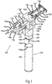
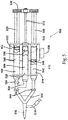
- Figure 1 illustrates a perspective view of a self-contained, pneumatically powered aerosol dispenser system 100.
- the system 100 is an exemplary overview of the invention as a whole, and it should be understood that the features shown and described with respect to Figure 1 could be incorporated with the features of the other figures where appropriate.
- the pneumatic aerosol dispensing system 100 generally comprises a main housing 102 and a handle 104.
- the housing 102 contains a pneumatic cylinder pressure regulator 106 (shown in phantom).
- the housing is affixed to a puncture head 108, which allows the handle 104 to be attached to the housing 102, preferably in a threaded or screw-like fashion.
- the handle 104 When removed from the puncture head 108, the handle 104 has an open top 104a that accepts a gas cartridge 124, which is inserted with its neck side toward the opening of the handle 104.
- a membrane 124a on the gas cartridge 124 is punctured by a beveled hypodermic syringe-type projection 140 in the puncture head 108 when the handle 104 and housing 102 are mated.
- the system 100 further comprises a pneumatic cylinder 110, a trigger 112, an aerosol pressure line 118, and a pneumatic cylinder pressure line 120 (shown in phantom).
- the trigger 112 is connected to and movable within the main housing 102, and is operably connected to, and is in-line with, the aerosol pressure line 118 and the pneumatic cylinder pressure line 120 so as to allow for momentary "on" in those pressure lines 118 and 120.
- the aerosol dispensing system 100 further comprises an aerosol pressure regulator 122.
- the projection 140 that pierces the gas cartridge 124 is connected to a lumen 142, which connects the aerosol pressure regulator 122 and the pneumatic cylinder pressure regulator 106.
- the aerosol pressure regulator 122 and the pneumatic cylinder pressure regulator 106 are housed within the main housing 102.
- the aerosol pressure line 118 is connected to the aerosol pressure regulator 122 at a first end 118a and the aerosol mixing head 116 at a second end 118b.
- the pneumatic cylinder pressure line 120 is connected at a first end 120a to the pneumatic cylinder pressure regulator 106 and to the input of the pneumatic cylinder 110 at a second end 120b.
- An optional pressure adjustment 136 located within the main housing 102 is connected to the aerosol pressure regulator 122 and the pneumatic cylinder pressure regulator 106 to adjust the outlet pressure of both regulators 122 and 106.
- the system 100 comprises one or more syringe barrels 114, permanently or releasably attached to the main housing 102, an aerosol mixing head 116, and a syringe manifold 130.
- the manifold 130 comprises individual lumens 130a that connect the individual syringe barrels 114 to the mixing head 116.
- the lumens 130a converge at a syringe outlet 131, which is in communication with the aerosol mixing head 116.
- the system 100 has a plunger coupler 126 for connecting one or more syringe plungers 128 to the pneumatic cylinder 110.
- a safety lock 132 is affixed to the main housing 102 and interacts with a lock notch 134 to allow or prevent movement of the syringe plungers 128.
- the syringe plungers 128 axially slide within the syringe barrels 114 and provide a seal so that the substances contained within the barrels 114 are prevented from escaping past the syringe plungers 128 (see also Figure 4 ).
- the pneumatic cylinder 110 is attached to the exterior of the main housing 102.
- the plunger coupler 126 is coupled, permanently or releasably, to the movable rod 127 of the pneumatic cylinder 110 and to the back end 129 of the syringe plungers 128.
- the pneumatic power could also be obtained by a gas line (not shown) to an external pressurized gas source (not shown), rather than using the gas cartridge 124.
- the gas cartridge 124 can be of the standard type used for pellet guns, paintball guns, airbrushes, and the like.
- the typical gas cartridge approximately holds between 5 to 100 grams of gas and, more preferably, holds a range of 10 to 25 grams of gas.
- the gas will be carbon dioxide, air, nitrogen, argon, nitrous oxide, or another inert gas.
- carbon dioxide will exist partially in the liquid phase when the pressure exceeds 850-PSI and is exposed to temperatures around 70-degrees Fahrenheit.
- the carbon dioxide cartridges will typically contain gas and liquid at a pressure of around 860-PSI.
- Nitrogen and air filled cartridges can be obtained commercially with pressures of 1800 PSI or higher.
- the pressure regulators 122 and 106 can be designed to use a first stage to step down the high pressure of the gas cartridge 124 to an intermediate pressure, 150 PSI for example, and then use a second stage to step down the intermediate pressure to the final operating pressure, expected to be in the range of 10 to 20 PSI.
- the pressure adjustment 136 can be a variable venturi or needle valve with a relief or bypass. Alternatively, the pressure adjustment 136 is eliminated from the system and the pressure level can be pre-set at an optimum value. Thus, there are no user operable controls for pressure adjustment, which is especially useful for non-critical applications or applications where the need for the lowest possible cost is a major consideration.
- the aerosol spray dispenser or apparatus thus comprises a gas pressure source that is contained within the dispenser, wherein the entire dispenser apparatus is portable, without any connections to external power or gas supplies.
- the system 100 is hand-held, wherein the trigger 112 is configured for depression and operation by the index finger of a user.
- the entire assembly 100 is ergonometric, lightweight, easy to hold, and to operate.
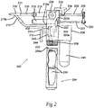
- FIG. 2 illustrates a side view of an electrically powered aerosol dispenser system 200.
- the principles of the dispenser 200 are similar to those of the dispenser 100, except the power source and pressure arrangement has been modified.
- the aerosol dispensing system 200 comprises a main housing 202 and a handle/battery compartment 204.
- the housing 202 further comprises an air cylinder pressure regulator 206 (shown in phantom).
- the housing 102 the main housing 202 is mated with and in electrical communication with a battery compartment attachment 208.
- the handle/battery compartment 204 preferably threads onto the battery compartment attachment 208 and houses a battery or batteries 224.
- An opening 204a in the handle 204 accepts the batteries 224 for proper electrical contact and insertion within the handle 204.
- the system 200 also comprises a pneumatic cylinder 210, a trigger 212, an aerosol pressure line 218, and a pneumatic cylinder pressure line 220.
- the trigger 212 is connected to and axially movable within, the main housing 202.
- the electrical aerosol dispensing system 200 further comprises an aerosol pressure regulator 222 (shown in phantom).
- the aerosol pressure regulator 222 and the pneumatic cylinder pressure regulator 206 are located within the main housing 202 and are connected to the gas output of a pressure reservoir 240.
- the system 200 also comprise a pressure adjustment 236, and a charge indicator 242.
- a power controller 244 is electrically connected to the battery compartment 208 and, also, to an electrical pneumatic pump 238.
- An on-off switch (not shown) may be inserted between the electrical connection between the battery compartment attachment 208 and the electrical pneumatic pump 238.
- the pressure reservoir 240 is connected to the gas outlet of the electrical pneumatic pump 238.
- the pressure reservoir 240 may be affixed to either the main housing 202 or to the electric pneumatic pump 238.
- the power controller 244 is preferably housed within the main housing 202.
- One or more syringe barrels 214 are releasably or permanently attached to the main housing 202 and are in fluid communication with an aerosol mixing head 216.
- the system has a plunger coupler 226 permanently or releasably attached to a movable rod 227 of the pneumatic cylinder 210 and to the back end 229 of the syringe plungers 228.
- a safety lock 232 affixed to the main housing 202 interacts with a lock notch 234, to allow or prevent movement of one or more of the syringe plungers 228.
- the syringe plungers 228 are slideably constrained to move axially within the syringe barrels 214 and prevent any substances contained therein from escaping past the syringe plungers 228.
- the pneumatic cylinder 210 is affixed to the exterior of the main housing 202.
- the aerosol pressure line 218 is connected to the aerosol pressure regulator 222 at a first end 218a and to the aerosol mixing head 216 at a second end 218b.
- the pneumatic cylinder pressure line 220 is connected at a first end 220a to the pneumatic cylinder pressure regulator 206 and to the input of the pneumatic cylinder 210 at a second end 220b.
- the trigger 212 is connected to, and is in-line with, the aerosol pressure line 218 and the pneumatic cylinder pressure line 220 so as to allow for momentary "on" in the pressure lines 218 and 220.
- the pressure adjustment 236 is connected to the main housing 202 with an interface control panel 237 exposed on the exterior of the main housing 202, and is in communication with the aerosol pressure regulator 222 and the pneumatic cylinder pressure regulator 206 to provide adjustment of the outlet pressure of both regulators 222 and 206.
- the charge indicator 244 is affixed to either the main housing 202 or the handle/battery compartment 204 and is electrically connected to the positive and negative terminals of the batteries 224.
- the electrical power can be obtained by a power cord (not shown) connected to an external power source (not shown), rather than using the batteries 224. While any battery arrangement is possible in the present invention, preferably the batteries 224 provide direct current power ranging from 1.5 to 24 volts, and, more preferably, in the range of 3 to 18 volts.
- the pressure reservoir 240 is optional but is a preferred embodiment.
- the operating pressure range of the electrically powered system 200 is within the range specified for the operating pressure of the pneumatically powered dispenser 100 illustrated in Figure 1 .
- the pressure adjustment 236 is optional and can be either an adjustable venturi or needle valve with a relief, or it can be an electrical volume control to control the speed of the electric pneumatic pump 238. Alternatively, a single pressure adjustment 236, providing a single delivery rate, is sufficient for many uses.
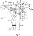
- FIG. 3 illustrates a side view of a manually powered aerosol dispenser system 300.
- the manual aerosol dispensing system 300 comprises a main housing 302, a handle/air pump 304, a pneumatic cylinder pressure regulator 306, a pneumatic cylinder 310, a trigger 312, one or more syringe barrels 314 permanently or releasably attached to the top portion of the main housing 302, an aerosol mixing head 316, an aerosol pressure line 318, and a pneumatic cylinder pressure line 320.
- the manual aerosol dispensing system 300 further comprises an aerosol pressure regulator 322, a pump lever 324, a plunger coupler 326, one or more syringe plungers 328, a syringe manifold 330, a safety lock 332, a lock notch 334, a pressure adjustment 336, a return spring 338, a pressure reservoir 340, and a pressure gauge 342.
- the main housing 302 is affixed to the handle/air pump 304.
- the top of the main housing 302 is affixed to the syringe barrels 314, either permanently or releasably.
- the trigger 312 is affixed to, and constrained so that at least a part of the trigger moves axially within, the main housing 302.
- the handle/air pump 304 contains the air pump (not shown).
- the outlet 308 of the handle/air pump 304 is connected to the air inlet 301 of the pressure reservoir 340.
- the air outlet 303 of the pressure reservoir 340 is connected to the air inlet 305 of the main housing 302.
- the pressure reservoir 340 may be affixed to the main housing 302 or to the handle/air pump 304.
- the aerosol pressure regulator 322 and the pneumatic cylinder pressure regulator 306 are housed within the main housing 302 and communicate with the air inlet 305 of the main housing 302. Any suitable linkage arrangement connects the pump lever 324 with an air pump mechanism (not shown) housed within the handle/air pump 304.
- the pump lever 324 is pivotably affixed to either the main housing 302 or the handle/air pump 304.
- the return spring 338 is affixed between the handle/air pump 304 and the pump lever 324.
- the safety lock 332 interacts with the lock notch 334 on one or more of the syringe plungers 328.
- the syringe plungers 328 axially slide within the syringe barrels 314 and prevent any substances contained therein from escaping past the syringe plungers 328.
- the syringe barrels 314 are connected to the syringe manifold 330, which has an outlet 331 communicating with the aerosol mixing head 316.
- the pneumatic cylinder 310 is affixed to the exterior of the main housing 302.
- the aerosol pressure line 318 is in fluid communication with the outlet of the aerosol pressure regulator 322 at a first end 318a and connected to the inlet of the aerosol mixing head 316 at a second end 318b.
- the pneumatic cylinder pressure line 320 is connected at a first end 320a to the outlet of the pneumatic cylinder pressure regulator 306 and to the input of the pneumatic cylinder 310 at a second end 320b.
- the plunger coupler 326 is permanently or releasably affixed to the movable rod of the pneumatic cylinder 310 and to the back end of the syringe plungers 328.
- the trigger 312 is connected to, and is in-line with, the aerosol pressure line 318 and the pneumatic cylinder pressure line 320 so as to allow for momentary "on" in the pressure lines 318 and 320.
- the pressure adjustment 336 is affixed to the main housing 302 and is in communication with the aerosol pressure regulator 322 and the pneumatic cylinder pressure regulator 306 to provide adjustment of the outlet pressure of both regulators 322 and 306.
- the pressure gauge 342 is affixed to either the main housing 202 or the handle/air pump 304 and is connected to the air outlet of the pressure reservoir 340, possibly with an electrical connection.
- power for the system 300 is generated by repetitively squeezing the pump lever 324 toward the handle/air pump 304.
- the pump lever 324 is biased away from the handle/air pump 304 by the return spring 338 and thus is ready for another pump cycle when released.
- the manual air pump can provide air pressure ranging from 10 to 500 PSI, and preferably in the range of 20 to 200 PSI.
- the pressure reservoir 340 is designed to store air and permit a buildup of pressure for even pressure delivery so that an immediate drop off of pressure will not occur when the trigger 312 is depressed.
- the operating pressure range of the manually powered system 300 is generally lower than the range specified for the operating pressure of the pneumatically powered dispenser 100 illustrated in Figure 1 .
- the pressure adjustment 336 is optional and can be either an adjustable venturi or needle valve with a relief, a single pressure adjustment, providing a single delivery rate and without user adjustability.
- the syringe plungers may alternatively be moved with a lever, such as the pump lever 324 or the trigger 312, rather than using the pneumatic cylinder 310 to generate the force, possibly with a common ratchet or pawl arrangement.
- FIG. 4 illustrates a partially cut-away, top view of an aerosol dispenser 400 comprising a single syringe mixing system that could be integrated into any of the arrangements and embodiments of the previous figures.
- the mixing aerosol dispensing system 400 comprises a main housing 402, a mixing syringe barrel 406, a syringe bypass channel 404, a separator plunger 408, a pneumatic cylinder 410, a pneumatic cylinder pushrod 412, one or more non-mixing syringe barrels 414, an aerosol mixing head 416, an aerosol pressure line 418, and a pneumatic cylinder pressure line 420.
- the system 400 further comprises one or more syringe plunger gaskets 422, a plunger coupler 426, one or more syringe plungers 428, a syringe manifold 430, a pressure adjustment 436, a liquid component 438, a dry component 440, a liquid component 442, one or more one way check valves 444, a disconnected plunger 446 and a plunger arm 448.
- the preferred drive system for the mixing syringe system 400 is the same as that described for Figures 1 , 2 , or 3 .
- the mixing syringe barrel 406 is filled with the dry component 440 in its front half and with the liquid component 438 in its back half.
- the two components 438 and 440 are separated by the separator plunger 408.
- the non-mixing syringe barrel 414 is filled with liquid component 442.
- the one way check valves 444 are affixed to the front of the non-mixing syringe barrel 414 and the mixing syringe barrel 406 to prevent air from flowing retrograde back into the syringe barrels 414 and 406 and prematurely aging or damaging the components 440 and 442.
- the one way check valves 444 allow for flow from the syringe barrels 414 and 406 to the manifold 430, but prevents fluid from flowing back into the barrels 406 and 414, which minimizes potential clotting and clogging.
- An additional valve such as a stopcock (not shown), can further be added to the outlets of the syringe barrels 414 and 406 or the syringe manifold 430, which is affixed between the syringe barrels 414 and 406 and the aerosol mixing head 416.
- the pneumatic cylinder pushrod 412 forces the plunger coupler 426 and the syringe plungers 428 toward the aerosol mixing head 416.
- the elastomeric gaskets on the distal ends of the syringe plungers 428 move toward the distal end or front of the syringe barrels 406 and 414.
- the separator plunger 408 will advance until its proximal end has passed beyond the proximal end of the bypass channel 404 in the mixing syringe barrel 406.
- the disconnected plunger 446 remains as a seal for the liquid component 442 and only moves when the plunger arm 448 makes contact with the disconnected plunger 446.
- the plunger arm 448 begins pushing the disconnected plunger 446, and the liquid component 438 is forced under pressure through the bypass channel 404 and into the front portion of the mixing syringe barrel 406 where it combines with dry component 440.
- the incorporation of several bypass channels 404 could be utilized to enhance mixing, but unless passive mixing occurs, the mixing may also be done by shaking the system to combine components 438 and 440.
- the combined components 438 and 440 are now a liquid with a viscosity substantially similar to that of water, 1.0 centipoise (cp).
- Additional pressure causes the syringe plungers 428 to continue advancing and the combined liquid component 438 and dry component 440 is ejected into the syringe manifold 430 along with the liquid component 442, which also preferably has a viscosity approximately similar to that of water.
- the components 438 + 440 and 442 are injected into the aerosol mixing head 416 where they are jetted into a high-pressure air stream powered by the aerosol pressure line 418 which is connected to the aerosol mixing head 416 from the bottom or side, as described with respect to the pressure lines 118, 218, and 318.
- the high-pressure air jet further helps mix and atomize the components, which are carried into a spray pattern, with the preferred pattern being a solid cone.
- Additional seals can be used to enhance shelf life of the product as can additional valves.
- detents, locks, and ratchets can be used to control the advancement of the syringe plunger 428, for example, stopping the plungers 428 at the bypass channel 404 and later at designated 1-cc volume stages, so that multiple 1-cc volume boluses of liquid from each syringe can be dispensed.
- the pressure adjustment 436 can be used to change the spray pattern and level of mixing for any specific arrangement as desired.
- FIG. 5 illustrates a top view of an alternate aerosol dispenser 500 comprising a multiple syringe mixing system.
- the system 500 will operate to mix compounds as described with respect to Figure 4 , but with each individual component housed in an individual syringe barrel.
- the multiple syringe mixing aerosol dispensing system 500 comprises a main housing 502, a mixing syringe barrel 506, a storage syringe barrel 504, a mixing manifold 508, a mixing reverse flow check valve 534, a pneumatic cylinder 510, a pneumatic cylinder pushrod 512, one or more non-mixing syringe barrels 514, an aerosol mixing head 516, an aerosol pressure line 518, and a pneumatic cylinder pressure line 520 (shown in phantom).
- the manual aerosol dispensing system 500 further comprises one or more syringe plunger gaskets 522, a plunger coupler 526, one or more syringe plungers 528, a syringe manifold 530, a pressure adjustment 536, a liquid component 538, a dry component 540, a second liquid component 542, one or more forward flow one-way check valves 544, a disconnected plunger 546, a plunger arm 548, and a passive plunger 550.
- the disconnected plunger 546 keeps the second liquid component 542 within the non-mixing syringe barrel 514.
- the mixing syringe barrel 506, the storage syringe barrel 504, and the non-mixing syringe barrel 514 are all shown in partial cutaway view to show internal details.
- the plunger arm 548 normally is disconnected from the disconnected plunger 546 and will move the disconnected plunger 546 when contact between the two is made.
- the plunger arm 548 and the syringe plunger 528 are connected to the plunger coupler 526 and move in unison, driven by the pneumatic cylinder pushrod 512 and the pneumatic cylinder 510. Any variations in volume delivered for a given chemical component are generated by changing the diameters of one or more of the syringe barrels 514 and 506.
- the plunger coupler 526 and respective plungers 528 and plunger arms 548 are initially provided in the forward or distal most location that provides for the specified volume of components in the syringe barrels 514 and 506.
- the plunger coupler 546 is withdrawn proximally until it stops in order to mix the components.
- Liquid component 538 is withdrawn from the storage syringe barrel 504 through the mixing manifold 508 and mixing check valve 534 into the mixing syringe barrel 506, where it mixes with dry component 540.
- the pneumatic cylinder pressure line 520 is then pressurized causing the pneumatic cylinder 510 to retract the pneumatic cylinder pushrod 512, the plunger arm 548 and the plunger coupler 526 distally.
- the syringe plungers 528 and plunger arms 548 move forward at a rate determined by the pressure exerted on the pneumatic cylinder 510, the area of the pneumatic cylinder 510 piston (not shown), and the friction in the system.
- the two liquid components are forcibly ejected through the forward flow one-way check valves 544, through the syringe manifold 530, and into the aerosol head 516, where gas under pressure is injected through the aerosol pressure line 518 to nebulize, atomize, or otherwise spray and mix the components.
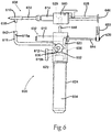
- Figure 6 illustrates a side view of an aerosol sealant applicator 600 comprising a detachable, disposable syringe head 608 and a reusable dispenser 632.
- the system 600 functions similar to the previous systems depicted in Figures 1 , 2 , and 3 .
- the detachable, disposable syringe head 608 comprises a syringe bracket 640, an attachment slot 629, a plurality of syringe plungers 628, a plurality of plunger flanges 646, a plurality of syringes 614, a syringe manifold 630, an aerosol mixing head 616, and an aerosol fitting 638.
- the reusable dispenser 632 comprises a main housing 602, an attachment prong 648, an aerosol pressure line 618, an aerosol pressure coupler 642, a pneumatic cylinder 610, a pneumatic cylinder pushrod 644, and a pneumatic cylinder pressure line 620.
- the reusable dispenser 632 further comprises a trigger 612, a pressure adjustment 636, a gas cartridge 624, a handle 604, an aerosol pressure regulator 622, one or more plunger coupler slots 650 and an air cylinder pressure regulator 606.
- the disposable syringe head 608 is configured for easy, secure attachment to, and detachment from, the main housing 602 and the plunger coupler 626.
- Quick connect fittings such as the attachment prong 648, which is affixed to the main housing 602 are configured to be inserted into and latch with the attachment slot 629, which is integrally affixed to the syringe bracket 640.
- the flanges 646 on the proximal end of the syringe plungers 628 slide into slots 648 in the plunger coupler 626.
- the plunger coupler is affixed at or near the proximal end of the pushrod 644.
- the pushrod 644 is affixed to a piston (not shown) within the pneumatic cylinder 610 and moves when differential pressure is applied thereon.
- the pneumatic cylinder 610 is affixed to the main housing 602.
- the pneumatic cylinder pressure line 620 is connected at a first end to the pneumatic cylinder 610.
- a reverse acting pneumatic cylinder 610 is used and the air cylinder pressure line 620 is affixed to the proximal end of the housing of the pneumatic cylinder 610.
- the pneumatic cylinder pressure line 620 is connected at its other end to the output of the air cylinder pressure regulator 606.
- the aerosol pressure line 618 is connected at a first end 618a to the aerosol pressure regulator 622 and at a second end 618b to an aerosol pressure coupler 642.
- the aerosol pressure coupler 642 is a quick connect that seals to the aerosol fitting 638, which is affixed, and operably connected, to the aerosol mixing head 616.
- the syringes 614 preferably can be standard syringes ranging in size from 0.25-cc to 60-cc, or they can be lyophilizing syringes, mixing syringes, or the like.
- the aerosol pressure regulator 622 and the air cylinder pressure regulator 606 may be the same device or they can be separate devices. They can have a common pressure source or they can operate as a two-stage pressure regulator where, for example, the aerosol pressure regulator 622 serves as the first stage and lowers the pressure to, for example, 30 PSI.
- the pneumatic cylinder pressure regulator 606 can then serve as the second stage and drop the pressure from 30 PSI to 12 PSI, for example.
- the pressure adjustment 636 can control the spring loading on a diaphragm adjust a needle valve in one or both of the regulators 622 and 606. Such values of pressure are appropriate for a 5/16-inch diameter pneumatic cylinder, while a larger diameter pneumatic cylinder can operate with lower pressures.
- the pressure adjustment 636 is affixed with its control surface externally affixed to the main housing 602.
- the main housing 602 and the air regulators 622 and 606 can be fabricated from polymers such as, but not limited to, ABS, polyolefin, PVC, polysulfone, polyamide, or the like or they can be fabricated from metal.
- Spring devices can be fabricated from spring metals such as, but not limited to, stainless steel 304, nickel cobalt alloys, titanium, nitinol, or the like.
- the regulators 606, 622 are preferably affixed within the main housing 602 although they could also be affixed externally thereto or about the handle 604.
- the trigger 612 is operably connected to a valve in either the inlet or outlet line to the regulators 606 and 622 so that depressing the trigger 612 opens the valve momentarily to operate the aerosol applicator.
- the trigger 612 is affixed to move axially within the main housing 602 or the handle 604.
- the trigger can have a spring return (not shown) to restore it to an "off' position when manual force is removed.
- the disposable syringe assembly 608 can be maintained sterile in single or double barrier aseptic packaging, be unpacked, and then be snapped onto the aerosol spray device 632.
- the gas cartridge 624 (shown in phantom) is captured within the handle 604, as described with respect to Figure 1 and the gas cartridge 124.
- the pneumatic cylinder 610 is replaced with a hydraulic cylinder and a hydraulic fluid source (not shown), which is pressurized by the gas outlet of the pneumatic cylinder pressure regulator 606.
- the entire assembly 600 can be supplied as a sterile assembly. Examples of possible sterilization processes include being steam sterilized, ethylene oxide sterilized, electron beam sterilized, or gamma irradiated with a source such as cobalt 60.
- the assembly 600 can be packaged in a PETG tray with a Tyvek® lid and then have an optional, second pouch sealed to enclose the sealed tray. This same packaging can be used for the disposable syringe assembly 608, as well, either separately or in one packaging.
- FIG. 7 illustrates a top view of a pneumatically driven aerosol dispenser 700 comprising a dual tank system without a separate pneumatic cylinder.
- the aerosol dispenser 700 comprises a main body 702, a plurality of slots 704 within the main body 702, a plurality of disconnected syringe plungers 708, a plurality of syringe barrels 714 shown in partial cutaway view, a mixing head 716, an aerosol spray tip 720, a plurality of syringe pressurization volumes 722, a syringe manifold 730, a bolus of sealing compound component 738, a pressure adjustment 736, a bolus of sealing compound component 742, a plurality of one way check valves 744, a plurality of syringe barrel end seals 750, a syringe barrel pressurization manifold 752, a plurality of syringe barrel inlet ports 754, and an aerosol pressure line 756.
- the main body 702 comprises slots 704, which are integral to the main body 702, or are created by separate external structures such as clips, brackets, or clamps, affixed to the main body 702.
- the syringe barrels 714 contain the two liquid components 738 and 742.
- the disconnected syringe plungers 708 reside within the inner lumen of the syringe barrels 714 and separate the liquid components 738 and 742 from air or other contaminants.
- the one-way check valves 744 which are connected within the line between the syringe manifold 730 and the syringe barrels 714, prevent retrograde flow of contaminants back into the syringe barrels 714.
- the outlet 731 of the syringe manifold 730 is connected to the inlet 732 of the mixing head 716.
- the aerosol spray head 720 is attached to the mixing head 716, which is also connected to the aerosol pressure line 756.
- the aerosol pressure line 756 is connected to a pressurized gas source (not shown), as has been described with the previous drawings and embodiments.
- the syringe barrel end seals 750 of which one is used on each syringe barrel 714, are affixed at the proximal end of each syringe barrel 714 and prevent the ingress or exit of fluids from or into the syringe barrels 714.
- the syringe pressure inlet line 752 is connected at one end to the syringe barrel inlet ports 754 and at the other end to a pneumatic pump, pneumatic pressure regulator, pneumatic air supply, hydraulic fluid supply, or the like, similarly as described with respect to the previous drawings and embodiments.
- the disconnected syringe plungers 708 move distally to force the components 738 and 742 to be separately ejected through separate channels in the distal end of the syringe barrels 714.
- the two components 738 and 740 are next forced through the separate one way check valves 744, through the separate paths of the manifold 730 and into the aerosol mixing head 716 where the two components 738 and 742 are jetted into space and mixed with air being jetted from the aerosol pressure line 756. No mixing occurs within the confines of the dispenser 700 until the components enter the mixing head 716, and, thus, the chance of the components 738 and 742 mixing, gelling, and clogging the system is minimized.
- the disconnected syringe plungers 708 are configured to seal against the syringe barrel 714 inner walls and to move axially within the syringe barrels 714.
- the plungers 708 are preferably fabricated from polymeric materials with no permeability and with at least a small amount of elastomeric resilience to provide a good seal.
- the perimeter of the plungers 708 can comprise ridges and valleys running circumferentially to enhance the seal against the syringe barrel 714.
- the length of the plunger 708 is preferably at least as long as its diameter and preferably 1.5 to 2 times the diameter. It is advantageous to configure the plungers 708 to have a conical distal end to improve movement under pressure.
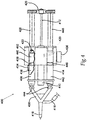
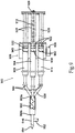
- FIG. 8 illustrates side view of an aerosol dispenser system 800 adapted to be inserted through a laparoscopic trocar or sheath 852.
- the laparoscopic aerosol dispenser system 800 comprises a main body 802, a handle 804, a pneumatic cylinder 810, a trigger 812, a plurality of syringe barrels 814, an aerosol spray tip 816, an aerosol pressure line 818, a pressure regulator 822, a syringe plunger coupler 826, a plurality of syringe plungers 828, a syringe manifold 830, a pressure adjustment 836, a plurality of one way check valves 844, a laparoscopic sheath seal 850, the laparoscopic sheath 852, a plurality of manifold extension lines 854, and a laparoscopic sheath hub 856.
- the aerosol dispenser system 800 is configured for use on a patient (not shown) to deliver sealant compound internally, through laparoscopic access devices, commonly known as sheaths or trocars.
- the aerosol spray tip 816 is affixed to the syringe manifold 830, which is connected to the manifold extension lines 854.
- the manifold extension lines 854 are connected at their proximal ends to the outlets of the syringe barrels 814.
- One-way check valves 844 are connected in the line somewhere between the outlet 815 of the syringe barrels 814 and the aerosol spray tip 816.
- the aerosol pressure line 818 is preferably parallel with and located as near the manifold extension lines 854 as possible to minimize the overall diameter of sheath tube 852 needed to encompass the assembly.
- the manifold extension lines 854, of which two are comprised by this embodiment, are likewise close together with minimum spacing to minimize diameter of the sheath tube 852.
- the inside diameter of the sheath tube 852 can range between 3mm and 20mm, with a preferred range of 8mm to 15mm.
- the length of the sheath tube 852 and sheath hub 856 ranges between 5 cm and 40 cm with a preferred range of 8 cm to 20 cm.
- the laparoscopic sheath seal 850 is affixed to the manifold extension lines 852 and aerosol pressure line 818.
- the sheath seal 850 prevents the escape of fluid, liquid and gas, proximal to itself when the laparoscopic sheath seal 850 is reversibly, or releasably, sealed against, or inside, the laparoscopic sheath hub 856.
- the assembly can further comprise endoscopes, video cameras, illumination light sources, and the like, all of which are not shown.
- the other components of the aerosol spray dispenser 800 are located proximal to the sheath seal 850 and are located outside the laparoscopic sheath and the patient during use.
- the aerosol spray dispenser system 800 can use the pneumatic actuation as described in Figure 1 , it can use some or all of the components described in Figures 2 or 3 , or it can be a hybrid of any of the aforementioned.
- the pneumatic cylinder 810 can be replaced with a hydraulic cylinder, the configuration of which would be almost identical to that of the pneumatic cylinder 810.
- the hydraulic cylinder is pressurized with liquid such as oil, water, or the like.
- the source of pressurized hydraulic fluid can be another cylinder, reservoir, or tank, not shown.
- the hydraulic fluid is either pumped into the hydraulic cylinder using a positive pressure pump or positive displacement pump, or it is simply exposed to pneumatic pressure and flows under the influence of this pre-determined and controlled pressure.
- the hydraulic system may have advantages over the pneumatic system in terms of consistency, since the hydraulic fluid is incompressible and acts more like a positive displacement system than the compressible pneumatic system that is being driven with gasses such as, but not limited to, nitrogen, carbon dioxide, air, helium, or the like.
- the system can be tailored to deliver material through a catheter, rather than a laparoscopic sheath.
- the catheter-based system requires the use of flexible aerosol pressure line 818 and a flexible manifold extension line 854.
- FIG. 9 illustrates a top view of an aerosol dispenser 900 comprising an apparatus to pre-mix the sealant components prior to exiting the distal end 954 of the dispenser 900, and wherein a buffering solution is added just prior to spraying.
- the aerosol dispenser 900 comprises a main housing 902, a buffering solution syringe barrel 904, a first component syringe barrel 906, a second component syringe barrel 914, a pneumatic cylinder (not shown), a pneumatic cylinder pushrod 912, an aerosol spray head 916, a plurality of syringe plunger gaskets 922, a plurality of syringe plungers 928, a syringe manifold 930, an optional pressure adjustment 936, a buffering solution 938, a liquid sealant component 940, a liquid sealant component 942, a plurality of one way check valves 944, a mixing chamber 950, and an aerosol pressure line 952.
- the buffering solution 938 can be selected from materials including, but not limited to, TRIS, phosphate, bicarbonate, and the like.
- the liquid sealant component 940 and component 942 are preferentially stored at a pH of around 7.0, which provides for a very long gel time, on the order of 10 minutes (600 seconds) or more. When they are injected through the manifold 930 and mixed in the mixing chamber 950, it is beneficial to inject the buffering solution 938 to accelerate the gel time to be on the order of 5 seconds, which occurs at a resultant pH of around 8.5 to 9.0.
- the mixing chamber 950 and aerosol spray head 916 will not clog or become blocked.
- the injection of the buffering solution 938 can occur at the proximal end 950a of the mixing chamber 950, it can occur at the distal end 950b of the mixing chamber 950, or it can occur somewhere intermediate the proximal end 950a and the distal end 950b of the mixing chamber 950.
- the overall gel time needs to be set so that three or more boluses of sealant can be dispensed and not become gelled within the mixing chamber 950 or aerosol spray head 916.
- the mixing chamber 950 can comprise stators or mixing vanes that cause two or three separate materials to be moved laterally into the flow path of another chemical to enhance mixing.
- the proportions of each component can advantageously be varied by advancing the syringe plungers independently, with independent or proportional control.
- the purpose of separate proportion control is to deliver a hydrogel having different properties such as gel time, gel strength, or degradation rate, appropriate and tailored for the intended use but with the same dispenser and components.
- a control dial can be comprised by the system which sets the individual rates of delivery according to simple descriptors such as "Fast Gel Time,” “Slow Gel Time,” “1-Week Degradation,” “Adhesion Barrier,” “Lung Sealant,” and the like. In such an arrangement, the amount of buffering solution or sealant component delivered can be adjusted by advancing de-coupled syringe plungers at separate rates of speed.
- one syringe barrel 406 comprises both powdered, lyophilized PEG 438 and unbuffered albumin solution 440, which are separated by a separator plunger 408 and selectively connected by a bypass channel 404.
- the other syringe barrel 414 is filled with a buffering solution 442. It is beneficial to store a protein component, such as albumin solution or the like, at a pH of around 7.0 in order to avoid degradation and then raise the pH just before it is dispensed.
- the syringe barrel 406 is filled with powdered, lyophilized PEG 438 and water or appropriate diluent 440, again separated by the separator plunger 408.
- the other syringe 414 is filled with albumin 442.
- the separator plunger 408 pushes past the proximal end of the bypass channel 404 allowing the albumin or diluent 440 to flow forward and mix with the powdered PEG 438.
- Cross-linking of the sealing compound components albumin and PEG4-SG occurs via nucleophilic substitution by a primary amine (lysine group) and a carbonyl (glutarate function).
- Albumin contains numerous amine groups that react readily with the carbonyl groups on each arm of a 4-arm PEG solution.
- the cross-linking reaction rate is dependent on the solution pH. For this reason, albumin is preferably buffered to a pH level that yields the desired gel time and gel strength. Increasing the pH causes amines to be more reactive.
- the albumin is buffered with 90 millimoles of TRIS and approximately 20 millimoles of sodium carbonate. Batch variation of albumin requires carbonate to be titrated until the final pH is reached. This buffer is selected to achieve a gel time and gel strength needed for arterial closure. Other buffers can be used in other embodiments, resulting in slightly different gel times and gel strengths
- a buffer Some factors to be considered when selecting a buffer include: ability of the buffer to maintain the desired pH, compatibility with the final compound and delivery system, product safety, stability, cost, and buffer capacity, or strength.
- the buffer could also be a phosphate buffer, a carbonate buffer, a borate buffer, and CHES.
- Another factor to consider is the ability to blend the buffer into the component, or components, being buffered during the spraying. This ability is determined, in part, by the kinetics of buffering the sealing compound solution. Each buffer may require a different time to shift the pH of the solution.
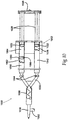
- FIG. 10 illustrates a top, partial cutaway view of an aerosol dispenser 1000 comprising an apparatus to pre-mix the sealant components within one of the syringe barrels and wherein a buffering solution is added just prior to spraying.
- the aerosol dispenser 1000 comprises a main housing 1002, a mixing syringe barrel 1006, an aerosol spray head 1016, a plurality of syringe plunger gaskets 1022, a syringe plunger coupler 1026, a plurality of syringe plungers 1028, a syringe manifold 1030, a buffering solution 1038, a buffer syringe barrel 1042, a dry sealant component A 1062, a liquid sealant component B 1064, a plurality of one way check valves 1044, a mixing chamber 1050, and an aerosol pressure line 1052.
- the mixing syringe barrel 1006 further comprises a bypass channel 1060 and a detached plunger seal 1066.
- the mixing syringe barrel 1006 is divided into two chambers by the detached plunger seal 1066.
- the detached plunger seal 1066 is constrained to move axially within the mixing syringe barrel 1006.
- the detached plunger seal 1066 is initially located proximal to the bypass channel 1060 and completely separates the dry sealant component 1062 from the liquid sealant component 1064.
- the dry sealant component 1062 can be, for example, polyethylene glycol (PEG) and the liquid sealant component 1064 can be albumin in water solution.
- the liquid sealant component 1064 advantageously can comprise additional water to make up for the difference in normal water that is pre-mixed with the dry sealant component A 1062 used in other embodiments.
- the chamber holding the liquid sealant component 1064 becomes pressurized and moves the detached plunger seal 1066 distally so that the bypass channel 1060 is exposed to the liquid sealant component 1064, thus allowing the liquid sealant component 1064 to flow through the bypass channel 1060 and mix with the dry sealant component A 1062.
- the buffering solution 1038 also contains water or other solvent and the amount of water added in the buffering solution 1038 needs to be factored into the total for the resultant sealant compound.
- the mixed, buffered sealant is ejected into the aerosol head 1016 and is combined with high-pressure gas, which enters through the aerosol pressure fitting 1052 prior to being ejected into space distal to the aerosol head 1016.
- the plunger coupler 1026 may be omitted, and each of the plungers 1028 and the plunger gaskets 1022 are advanced at different rates so that control over mixing parameters can be maximized.
- the syringe plunger coupler 1026 can be advanced or retracted using pneumatic force, hydraulic force, electromagnetic force, or manually applied force.
- the dry sealant component 1062 can be pressurized with an inert gas such as nitrogen, argon, helium, or the like, to prevent or delay oxidation and increase shelf life.
- the pressurization is preferably set at relatively low levels, less than 5 PSI, and is easily overcome by the pressure exerted by distal movement of the plungers 1028.
- the detached plunger seal 1066 is fabricated from silicone elastomer, polytetrafluoroethylene, fluorinated ethylene propylene, polyurethane, thermoplastic elastomer, or the like.
- the detached plunger seal 1066 can further be coated with metallic foil, polymer coatings such as silicone, glass, or the like, on the proximal surface, the distal surface or both to minimize material diffusion therethrough.
- the mixing syringe barrel 1006 can have a smaller inner diameter in the region just proximal to the location of the detached plunger so that pressurization is not able to push the detached plunger proximally against the inward transition zone between the two inner diameters.
- the syringe plunger gaskets 1022 do not need to have entirely perfect seals and are configured for high levels of radial expansion to maintain the seal even after the plunger 1066 is advanced distally into the larger internal diameter portion of the mixing syringe barrel 1006.
- the high levels of expansion can be enabled using folded circumferential ribs or very low durometer resilient materials, or both.
- the syringe manifold 1030, the one-way check valves 1044, and the mixing chamber 1050 can be coated with materials that have a low pH and are thus, acidic.
- the acidic surfaces will help prevent gelling of the mixed sealing compound while within the internal lumens of the dispenser 1000.
- Further measures to prevent clogging of the device 1000 include providing a bolus of gas, water, alcohol, or other substance to flush out the internal volume of the manifold 1030 and the mixing chamber 1050 after forward, or distal, movement of the syringe plungers 1028 has ceased.
- a bolus of materials is preferably automatically dispensed so that the user does not have to perform any conscious cleaning procedures.
- Ball valves or stopcocks can be used instead of the one-way check valves 1044 and those ball valves can be manually operated or motor, pneumatic, hydraulic, or electrical solenoid driven.
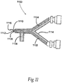
- FIG 11 illustrates an alternate aerosol tip configuration wherein the protein component channel exit is positioned proximal to the cross-linking component channel exit.
- the aerosol tip configuration 1100 comprises a protein component channel 1102, a cross-linking component channel 1104, an aerosol channel 1106, a protein component channel end 1108, a cross-linking channel end 1110, an aerosol channel end 1112, and a support structure 1114.
- the protein component channel 1102 can be a metal or polymer axially elongate tube with an outer diameter and an inner diameter, which defines the outer wall of the lumen.
- the cross-linking component channel 1104 comprises metal or polymeric axially elongate tube with an outer diameter and an inner diameter, which defines the outer wall of the flow lumen.
- the aerosol channel 1106 comprises metal or polymeric axially elongate tube with an outer diameter and an inner diameter, which defines the outer wall of the flow lumen through which high-pressure gas passes to generate the aerosol effect.
- the protein component channel 1102 has a distal end or exit 1108, which is positioned proximal relative to the end or exit 1110 of the cross-linking component channel 1104.
- the area forms a mixing area 1116, similarly to the mixing heads described with respect to the prior drawings and embodiments.
- the mixing area or mixing head of the present invention should be read broadly to include any area or structure that provides a mixing area that will not allow clogging or clotting of the general delivery device.
- the relative separation between the two channel ends 1108 and 1110 is between 1 and 10 mm with a preferred range of 2 to 7 mm.
- the cross-linking component is mixed with the protein in space far from the lumen of the protein component channel 1102 so that the protein component channel 1102 cannot receive any backsplash or backflow of crosslinked protein, which might clog the lumen.
- the dilution of the protein, which contacts the cross-linking fluid reduces the clogging propensity of the gelled compound inside the delivery system.
- a small volume of protein mixing with a large volume of cross-linking agent results in less propensity to gel than if the same volume of cross-linking agent is mixed with a larger volume of protein.
- the bolus of protein can be diluted with water to achieve the correct volume ratio. For example, with a ratio of PEG to albumin of 10 to 1, the initial integrity of the compound and its propensity to gel is lower than if the ratio of PEG to albumin is 1 to 10. The flow of cross-linking agent through the channel 1104 will keep this channel clear from clogging or obstruction.
- the aerosol channel end 1112 is positioned either proximal or distal to the protein component channel end 1108, although it is preferably located proximal to the protein component channel end 1108, as illustrated in Figure 11 .
- the support structure 1114 is generally polymeric although it can be metal and supports the channels 1102, 1104 and 1106, although it could be polymeric and said channels can be integrally formed with the polymeric support structure 1114 by injection molding, machining, or the like.
- FIG. 12 illustrates a spray applicator 1200 for a multi-component gel, wherein the applicator 1200 comprises line and spray head cleaning means.
- the spray applicator 1200 comprises a carrier housing 1202, a carrier back plate 1204, a plunger coupler 1206, a spring plate 1208, a spray head 1210, a handle 1212, a trigger 1214, a ratchet lock 1216, a ratchet rod 1218 further comprising a plurality of ratchet rod teeth 1244, a plurality of component syringes 1220, further comprising component syringe plungers 1254, a plunger spring 1222, a lock spring 1224, a valve spring 1226, a plurality of 1-way valves 1228, a manifold 1230, a ratchet wheel 1232 further comprising a plurality of ratchet wheel teeth 1242, a flushing valve 1234, a valve inlet line 1236, a valve outlet line 1238,
- the carrier housing 1202 is a clip that holds the syringes 1220 1240 to the housing 1202, with the handle being affixed, either permanently or removably, to the handle 1212.
- the carrier housing 1202 surrounds the syringes 1240 and 1220 so as to restrict axial and lateral syringe motion.
- the carrier back plate 1204 can be integral to the carrier housing 1202 or it can be separate and affixed by bonding, connectors, or the like.
- the syringes 1220 are inserted from the top and the groove 1252 separates the carrier housing 1202 and carrier back plate 1204 such that a flange on the back of each of the syringe barrels 1220 and 1240 is trapped by the groove 1252 and restricted from axial motion.
- the syringes 1220 and 1240 can be inserted from the top or other lateral direction, so that the flange fits into the groove 1252 or the syringes 1220 and 1240 can be inserted from the back of the carrier housing 1202 and the carrier back plate 1204 attached by connectors such as screws, quick connects, clips, or the like.
- the plunger coupler 1206 traps flanges on the back of the component syringe plungers 1254 in a groove such that movement of the plunger coupler 1206 in the forward or backward direction causes axial movement of the component syringe plungers 1254.
- the plunger coupler 1206 is affixed to the ratchet rod 1218.
- the plunger coupler 1206 is affixed to the spring plate 1208, which further retains the plunger spring 1222 from lateral motion by way of an internal lip (not shown).
- the plunger spring 1222 rests against and biases the flushing syringe plunger 1256 to move forward.
- the trigger 1214 is constrained to rotate about the axle 1246, which is constrained from lateral and axial motion by the handle 1212.
- the trigger 1214 is affixed to the ratchet wheel 1232 and rotates in a 1:1 ratio with the ratchet wheel 1232.
- the ratchet wheel 1232 moves the ratchet wheel teeth 1242 against the ratchet rod teeth 1244 to advance the ratchet rod 1218 forward.
- Reverse motion of the ratchet wheel 1232 causes the ratchet wheel teeth 1242, which are spring loaded to retract, biased by the ramps on the forward side of the ratchet rod teeth 1244 to allow relative reverse motion between the ratchet wheel teeth 1242 and the ratchet rod teeth 1244.
- the ratchet lock 1216 is slideably affixed within the handle 1212 so as to permit axial motion only, biased upward by the lock spring 1224 so that its sharp upper end engages the ratchet rod teeth 1244.
- Downward pressure on the ratchet lock 1216 by ramping over the sloped forward edges of the ratchet rod teeth 1244 disengages its upper end from the ratchet rod teeth 1244 and permits the ratchet rod teeth 1244 to move forward.
- Downward manual pressure on the ratchet lock 1216 disengages the upper end of the ratchet lock 1216 form the ratchet rod teeth 1244 and permits the ratchet rod teeth 1244 and the ratchet rod 1218 to move backward.
- the plunger coupler 1206 forces the plurality of component syringe plungers 1254 to move forward to expel the plurality of gel components 1250 through the plurality of one way valves 1228 into the manifold 1230 and out the mixing head 1210. Forward motion of the plunger coupler 1206 also compresses the plunger spring 1222, which then exerts increasing force on the flushing syringe plunger 1256 and pressurizes the flushing fluid 1248.
- a pressure assist mechanism (not shown) may be employed to ensure an even flow.
- a spring or gas-assisted mechanism can be employed to even trigger pulls.
- the spring or gas-assist absorbs heavy pulls, and redistributes the pull energy to evenly dispense material. In light pulls, the spring or gas-assist may simply absorb the pull energy and dissipate it within the system, dispensing only upon appropriate pressure. Other alternative arrangements will be apparent.
- the flushing valve 1234 is closed when the trigger 1214 is being pulled toward the handle 1212 so pressurized flushing fluid 1248 cannot flow through the system.
- the flushing valve 1234 is affixed to the trigger 1214.
- the valve spring 1226 is affixed at one to the handle 1212 and constrained from lateral motion. The valve spring 1226 presses against the actuator, or button, of the flushing valve 1234 to keep the flushing valve 1234, which is normally open, in the closed position.
- the valve spring 1216 is compressed and maintains closure of the flushing valve 1234.
- the force exerted by the valve spring 1216 is lessened and the normally open flushing valve 1234 opens.
- the inlet of the flushing valve 1234 is connected to the outlet of the flushing syringe 1240 by the valve inlet line 1236.
- the outlet of the flushing valve 1234 is connected to the manifold 1230 by the valve outlet line 1238.
- the dispenser or applicator 1200 works by preparing the gel components 1250. This may include having to pre-mix powdered materials such as polyethylene glycol and water or buffered water.
- the mixing head 1210 is aimed at the target tissue.
- the trigger 1214 is pulled toward the handle 1212. This causes the flushing valve 1234 to close and the plunger coupler 1206 to be pulled forward causing ejection of the gel components 1250 so that they are sprayed onto the target tissue through the mixing head 1210.
- a solid cone spray pattern of approximately 0.5 to 10 cm diameter at 1 to 20 cm distance is beneficial in these applications.
- the flushing valve 1234 is closed so the flushing syringe plunger 1256 cannot move forward even though it is under increasing pressure exerted by the plunger spring 1222 which is increasingly compressed by the plunger coupler 1206.
- the trigger 1214 is pulled through sufficient distance so that it preferably completely discharges a pre-determined amount of gel component from each syringe 1220.
- Such pre-determined amount of gel component 1250 can range from 0.1-cc to 5-cc with a preferred range of 0.5 to 2-cc.
- the flushing fluid 1248 can be ejected in volumes of 0.1-cc to 10-cc with a preferred range of 0.25 to 1-cc.
- the flushing fluid can be water, buffered water, saline, or in a pneumatic embodiment, high-pressure air, carbon dioxide, nitrogen, or other gas.
- the flushing fluid 1248 cleans out the manifold 1230 and the mixing head 1210 to prevent clogging.
- the flushing fluid 1248 can be routed into the gel component lines at a point even closer to the one-way valves 1228 to achieve additional flushing. It is, practically, only necessary to flush out those lines where mixed gel components flow.
- the separate gel components 1250 are preferably not capable of clogging the lines by themselves.
- Syringe 1240 and 1220 volumes can range from 0.5-cc to 20-cc with a preferred range of 1-cc to 10-cc.
- the gel component syringes 1220 can be lyophilizing syringes to permit in-syringe mixing of components following selective breakdown of an internal barrier between multiple syringe contents.
- the flushing valve 1234 is a two way normally closed valve and the valve spring 1216 is configured only to bias and push the trigger 1214 away from the handle 1212 without contacting or operating the flushing valve 1234 in any way.
- the flushing valve 1234 is closed when the trigger is away from the handle 1212 or as the trigger 1214 is pulled toward the handle 1212.
- the flushing valve 1234 opens only when the trigger 1214 is pushed against the handle 1212 such that the pushbutton on the flushing valve 1234 is depressed by the handle, thus causing flushing valve 1234 opening and flushing fluid 1248 can now flow through the manifold 1230 and spray head 1210.
- the trigger 1214 When the trigger 1214 is released the handle 1212 no longer pushes on the button of the flushing valve 1234 and the flushing valve 1234 closes.
- the flushing applicator system 1200 can have the flushing valve 1234 affixed to the handle 1212 while the valve spring 1226 is constrained between the one-way valve 1234 button and the trigger 1214.
- flexible lines are not necessary and the valve inlet and outlet lines 1238 and 1238, respectively can be routed through the handle 1212 and be invisible to the user.
- the flushing system can be achieved using high-pressure gas to clean out the line.
- the high-pressure gas can be sourced from a canister of pressurized gas contained within the applicator.
- the flushing system can use position sensors, and electronic controls to determine when to open the flushing valves. Such systems can be powered by on-board batteries and use sensors such as Hall-effect sensors and magnets or LVDT devices to gauge when to execute line flushing.
- the flushing system can use a normally open or normally closed valve, which opens or closes to allow the flow of purging gas (depending on the type of valve and flow channel configuration) when compressed against the trigger 1214 and the handle 1212. It is beneficial not to flush the lines when the gel is being discharged.
- the material used to seal the vessel defect can comprise human albumin and polyethylene glycol solution, or it may comprise a multi-part mixture of non-human or recombinant albumin and polyethylene glycol.
- Additional chemicals may be injected along with, or prior to, the sealing components in order to cause a beneficial change in the polymerization characteristics, adhesive characteristics, or lubricity of the resultant sealing matrix.
- the sealing compound may be resorbable or non-resorbable in the body. Further, the sealing compound may have its lubricity and adhesive characteristics altered, for instance by changing the pH of the environment.
- the dispenser can be used for thoracoscopic use as well as laparoscopic use.
Claims (15)
- Un dispositif (100) pour distribuer un composé scelleur à composants multiples, ledit dispositif (100) comprenant :au moins deux réservoirs contenant des composants indépendants (114) ;une tête de mélange (116) ayant une pluralité d'entrées et une sortie, chacune desdites entrées étant raccordée à l'un desdits réservoirs (114), ladite tête de mélange (116) fournissant une zone de mélange pour lesdits composants indépendants afin de former ledit composé scelleur à composants multiples ;un moyen (128) pour faire avancer lesdits composants indépendants jusque dans ladite tête de mélange (116) ;une source de gaz sous pression (124) raccordée par l'intermédiaire d'une conduite de pression aérosol (118) à ladite tête de mélange (116) afin de faciliter le mélange des au moins deux composants indépendants et du gaz ;ladite source de gaz sous pression étant également raccordée par l'intermédiaire d'une conduite de pression de cylindre pneumatique (120) à un cylindre pneumatique (110),ledit cylindre pneumatique (110) étant raccordé fonctionnellement audit moyen pour faire avancer lesdits composants indépendants jusque dans ladite tête de mélange ; etun moyen de régulation de pression aérosol (122) pour propulser ledit gaz sous pression jusque dans ladite tête de mélange (116) par l'intermédiaire de ladite conduite de pression aérosol (118), ledit gaz propulsé forçant ledit composé scelleur à composants multiples à travers ladite sortie de tête de mélange (116) ; etun moyen de régulation de pression de cylindre pneumatique (106) pour propulser du gaz à partir de ladite source de gaz sous pression (124) vers ledit cylindre pneumatique (110).
- Le dispositif (100) selon la revendication 1 comprenant en outre un logement (102), lesdits réservoirs (114) étant situés à l'intérieur dudit logement (102).
- Le dispositif (100) selon la revendication 2 dans lequel lesdits réservoirs (114) sont attachés de manière amovible audit logement (102).
- Le dispositif (100) selon la revendication 1 dans lequel ladite source de gaz sous pression (124) est raccordée de manière amovible audit logement (102).
- Le dispositif (100) selon la revendication 1 dans lequel ledit moyen (128) pour faire avancer lesdits composants comprennent un piston (128) raccordé à un dispositif pneumatique (110), ledit dispositif pneumatique (110) étant en communication avec ladite source de gaz sous pression (124).
- Le dispositif (100) selon la revendication 1 dans lequel ledit moyen de propulsion (122) comprend un dispositif mécanique.
- Le dispositif (100) selon la revendication 1, dans lequel le dispositif (100) est une seringue à composants multiples, ladite seringue comprenant :un logement (102) ;dans lequel lesdits au moins deux réservoirs (114) sont raccordés audit logement (102), ladite source de gaz sous pression (124) est attachée audit logement (102) ; etdans lequel ladite tête de mélange (116) est une tête de seringue située sur ledit logement (102).
- La seringue (100, 400) selon la revendication 7 dans laquelle au moins un desdits réservoirs (114, 414) comprend en outre une première chambre et une deuxième chambre, chacune desdites chambres contenant un composé individuel (440, 438), lesdits composés individuels (440, 438) formant l'un desdits composants indépendants.
- La seringue (100) selon la revendication 7 dans lequel lesdits réservoirs (114) sont raccordés de manière détachable audit logement (102).
- La seringue (100) selon la revendication 7 dans laquelle ledit moyen d'avancement (128) pour chacun desdits réservoirs (114) est commandé indépendamment.
- La seringue (100) selon la revendication 7 comprenant en outre une poignée attachée audit logement (102), ladite source de gaz sous pression (124) étant située à l'intérieur de ladite poignée.
- La seringue selon la revendication 11 dans laquelle ladite poignée est détachable dudit logement (102).
- La seringue (100) selon la revendication 7, ladite seringue comprenant en outre une paire de réservoirs (114).
- La seringue (100) selon la revendication 13, dans laquelle l'un desdits réservoirs (114) est pré-rempli avec des albumines, ladite autre seringue étant pré-remplie avec du polyéthylène glycol.
- La seringue (100, 800) selon la revendication 7 comprenant en outre une gaine (852), ladite gaine (852) entourant ladite tête de mélange (116, 816).
Applications Claiming Priority (2)
| Application Number | Priority Date | Filing Date | Title |
|---|---|---|---|
| US32087710P | 2010-04-05 | 2010-04-05 | |
| PCT/US2011/031235 WO2011127045A2 (fr) | 2010-04-05 | 2011-04-05 | Méthode et appareil d'application d'un agent de scellement des plaies |
Publications (3)
| Publication Number | Publication Date |
|---|---|
| EP2555813A2 EP2555813A2 (fr) | 2013-02-13 |
| EP2555813A4 EP2555813A4 (fr) | 2017-01-11 |
| EP2555813B1 true EP2555813B1 (fr) | 2019-08-07 |
Family
ID=44710523
Family Applications (1)
| Application Number | Title | Priority Date | Filing Date |
|---|---|---|---|
| EP11766590.1A Active EP2555813B1 (fr) | 2010-04-05 | 2011-04-05 | Appareil d'application d'un agent de scellement des plaies |
Country Status (7)
| Country | Link |
|---|---|
| US (1) | US10987093B2 (fr) |
| EP (1) | EP2555813B1 (fr) |
| JP (2) | JP2013523336A (fr) |
| CN (1) | CN102933243A (fr) |
| BR (1) | BR112012025498A2 (fr) |
| CA (1) | CA2795261C (fr) |
| WO (1) | WO2011127045A2 (fr) |
Families Citing this family (44)
| Publication number | Priority date | Publication date | Assignee | Title |
|---|---|---|---|---|
| US20090038701A1 (en) | 2006-01-17 | 2009-02-12 | Baxter International Inc. | Device, system and method for mixing |
| US7837656B2 (en) * | 2006-03-27 | 2010-11-23 | Tyco Healthcare Group Lp | Dual air regulated spray applicator |
| US8734400B2 (en) * | 2008-09-19 | 2014-05-27 | C.R. Bard, Inc. | Medical device securement system |
| CN102438531B (zh) * | 2009-05-06 | 2016-05-11 | 斯恩蒂斯有限公司 | 用于施加密封剂的方法和装置 |
| AU2011229797B2 (en) * | 2010-03-23 | 2017-02-16 | Hyperbranch Medical Technology, Inc. | Disposable syringe applicators for multi-component formulations, and methods of use thereof |
| CN102917736A (zh) * | 2010-04-05 | 2013-02-06 | 尼奥文股份有限公司 | 具有自净化来防止堵塞的用于递送水凝胶组合物的系统、设备及方法 |
| KR101458163B1 (ko) | 2012-03-12 | 2014-11-04 | 주식회사 글로원 | 주사약 분사기 및 상기 분사기를 포함하는 주사약 분사장치 |
| US20140121699A1 (en) * | 2012-10-31 | 2014-05-01 | Nordson Corporation | Device and method for dispensing a liquid and a gas |
| US20150265821A1 (en) * | 2012-11-05 | 2015-09-24 | Smith & Nephew, Inc. | Assemblies and methods for fluid delivery |
| EP2969159B1 (fr) | 2013-03-15 | 2019-10-02 | Neomend, Inc. | Buse de pulvérisation à mélange centrifuge |
| WO2014186401A2 (fr) * | 2013-05-13 | 2014-11-20 | Arizona Board Of Regents On Behalf Of The University Of Arizona | Aerostase en chirurgie pulmonaire |
| JP6132404B2 (ja) * | 2013-06-26 | 2017-05-24 | アネスト岩田株式会社 | 塗布器具 |
| US10085729B2 (en) * | 2014-03-06 | 2018-10-02 | Ethicon, Inc. | Methods and devices for forming biomedical coatings using variable mixing ratios of multi-part compositions |
| US10610226B2 (en) | 2014-06-10 | 2020-04-07 | Ethicon Endo-Surgery, Inc. | Methods and devices for sealing stapled tissue |
| JP6672182B2 (ja) * | 2014-06-10 | 2020-03-25 | エシコン エルエルシーEthicon LLC | ステープル留めされた組織を封止するための方法及び装置 |
| JP6654188B2 (ja) * | 2014-09-11 | 2020-02-26 | オムリックス・バイオファーマシューティカルズ・リミテッドOmrix Biopharmaceuticals Ltd. | 医療用アプリケータに対する追加物 |
| US10183132B2 (en) * | 2014-09-11 | 2019-01-22 | Ethicon Llc | Methods and devices for co-delivery of liquid and powdered hemostats and sealants |
| WO2017011668A1 (fr) * | 2015-07-14 | 2017-01-19 | Boston Scientific Scimed, Inc. | Cathéters de distribution de gel, systèmes, et procédés |
| KR102657608B1 (ko) * | 2015-09-29 | 2024-04-15 | 템플 유니버시티-오브 더 커먼웰쓰 시스템 오브 하이어 에듀케이션 | 휴대용 스피너 및 사용 방법 |
| US10600299B2 (en) * | 2015-10-15 | 2020-03-24 | Steven Benjamin Faubion | Smoke detector with removable battery compartment |
| US10155063B2 (en) | 2015-11-12 | 2018-12-18 | University Of Virginia Patent Foundation | Methods for vas-occlusive contraception and reversal thereof |
| JP2017176713A (ja) * | 2016-03-31 | 2017-10-05 | テルモ株式会社 | 塗布具 |
| AU2017283496B2 (en) * | 2016-06-14 | 2020-07-16 | Renovacare Sciences Corp. | Modular device for cell spraying |
| CN106620974A (zh) * | 2016-08-26 | 2017-05-10 | 中国人民解放军军事医学科学院野战输血研究所 | 一种电控气动组织修复喷洒装置及组织修复喷洒方法 |
| CN106362271A (zh) * | 2016-08-29 | 2017-02-01 | 名高医疗器械(昆山)有限公司 | 一种药物喷雾器 |
| US11202862B2 (en) * | 2017-02-02 | 2021-12-21 | Guo-Luen HUANG | Pressurized gas injection device and method |
| EP3679863A4 (fr) * | 2017-09-08 | 2021-02-24 | Samyang Biopharmaceuticals Corporation | Ensemble de seringue de produit d'étanchéité |
| KR20200085284A (ko) * | 2017-11-04 | 2020-07-14 | 알타비즈 엘엘씨 | 가스 구동식 유체 주입 시스템 |
| CN107790332A (zh) * | 2017-11-27 | 2018-03-13 | 深圳市华星光电技术有限公司 | 涂布喷头及涂布机、液晶模组的制造方法 |
| US20210077799A1 (en) * | 2018-04-16 | 2021-03-18 | Renovacare Sciences Corp. | Spray deposition system and its use for treating a living being |
| US11517527B2 (en) * | 2018-11-05 | 2022-12-06 | Ethicon, Inc. | Systems, devices and methods for making and expressing foam used in medical procedures |
| JP2022506078A (ja) * | 2018-11-13 | 2022-01-17 | コントラライン,インコーポレイテッド | 生体材料を送達するためのシステムおよび方法 |
| KR20210143849A (ko) * | 2019-03-22 | 2021-11-29 | 씨. 알. 바드, 인크. | 폐 시술에 사용하기 위한 실란트 전달 장치와 이를 제조하기 위한 시스템 및 방법 |
| US20220305234A1 (en) * | 2019-09-05 | 2022-09-29 | Texas Heart Institute | Electrically Conductive Hydrogels Usable As Lead Extensions, Apparatus For Delivery Of A Hydrogel Into The Vasculature, and Methods Of Treating Ventricular Arrhythmia With Electrically Conductive Hydrogels Injected In The Venous System |
| IT201900016502A1 (it) * | 2019-09-17 | 2021-03-17 | Carlo Cavazzini | Dispositivo medico di ausilio nel trattamento delle varici o trattamenti similari |
| US20210100543A1 (en) * | 2019-10-04 | 2021-04-08 | Ethicon, Inc. | Dispensing systems and devices having anti-clogging spray tips for dispensing two or more fluids that react together |
| CN114945313A (zh) * | 2019-11-18 | 2022-08-26 | 波士顿科学国际有限公司 | 用于经内窥镜分配药剂的医疗装置以及相关的使用方法 |
| EP4048361A1 (fr) * | 2019-12-03 | 2022-08-31 | Boston Scientific Scimed, Inc. | Dispositifs d'administration d'agent |
| CN115916417A (zh) * | 2020-08-21 | 2023-04-04 | 巴克斯特国际公司 | 用于混合并分配多组分组合物的手持气体喷雾系统 |
| CN112295093B (zh) * | 2020-09-30 | 2022-12-06 | 广州迈普再生医学科技股份有限公司 | 一种医用胶电动喷涂装置 |
| WO2023091134A1 (fr) * | 2021-11-17 | 2023-05-25 | Cft Llc | Applicateur |
| CN112725908A (zh) * | 2020-12-23 | 2021-04-30 | 青岛大学 | 一种便携式溶液喷射纺丝装置 |
| WO2023070070A1 (fr) * | 2021-10-22 | 2023-04-27 | Boston Scientific Medical Device Limited | Systèmes de production de mélanges |
| US20230338658A1 (en) * | 2022-04-25 | 2023-10-26 | Frank Levy | Apparatus and method for producing an enriched medical suspension |
Family Cites Families (36)
| Publication number | Priority date | Publication date | Assignee | Title |
|---|---|---|---|---|
| US4067479A (en) * | 1975-07-31 | 1978-01-10 | Products Research & Chemical Corporation | Two part material meter-mix dispenser apparatus |
| AT382783B (de) | 1985-06-20 | 1987-04-10 | Immuno Ag | Vorrichtung zur applikation eines gewebeklebstoffes |
| US5064098A (en) * | 1990-02-23 | 1991-11-12 | Physical Systems, Inc. | Dual component dispenser gun |
| JP2596623Y2 (ja) * | 1992-07-16 | 1999-06-21 | 財団法人化学及血清療法研究所 | 生体組織接着剤用簡易塗布器具 |
| US5582596A (en) * | 1992-09-26 | 1996-12-10 | Juridical Foundation The Chemo-Sero-Therapeutic Research Institute | Applicator for applying a biocompatible adhesive |
| WO1995031138A1 (fr) * | 1994-05-12 | 1995-11-23 | Omrix Biopharmaceuticals S.A. | Dispositif manuel destine a distribuer un fluide |
| US6033401A (en) | 1997-03-12 | 2000-03-07 | Advanced Closure Systems, Inc. | Vascular sealing device with microwave antenna |
| JPH11506649A (ja) * | 1995-06-06 | 1999-06-15 | クウォンティック バイオメディカル パートナーズ | 傷シーラント調製物並びに適用デバイス及び方法 |
| US5816445A (en) * | 1996-01-25 | 1998-10-06 | Stainless Steel Coatings, Inc. | Method of and apparatus for controlled dispensing of two-part bonding, casting and similar fluids and the like |
| ATE232060T1 (de) | 1996-09-10 | 2003-02-15 | Omrix Biopharm Sa | Vorrichtung zur applikation einer mehrkomponentenflüssigkeit |
| US6743248B2 (en) | 1996-12-18 | 2004-06-01 | Neomend, Inc. | Pretreatment method for enhancing tissue adhesion |
| US6783514B2 (en) | 1997-01-31 | 2004-08-31 | United States Surgical Corporation | Fibrin sealant applicator |
| DE19709896C1 (de) * | 1997-03-11 | 1998-12-24 | Omrix Biopharm Sa | Applikator zum Auftragen eines Ein- oder Mehrkomponenten-Fluids und Verfahren zum Aufsprühen eines derartigen Fluids |
| US6371975B2 (en) | 1998-11-06 | 2002-04-16 | Neomend, Inc. | Compositions, systems, and methods for creating in situ, chemically cross-linked, mechanical barriers |
| US6733515B1 (en) | 1997-03-12 | 2004-05-11 | Neomend, Inc. | Universal introducer |
| US6770050B2 (en) | 1997-04-14 | 2004-08-03 | Baxter International Inc. | Multipurpose fluid applicator and method, with surgical uses |
| CA2315802C (fr) * | 1997-12-19 | 2007-09-04 | United States Surgical Corporation | Systeme de distribution a deux elements |
| US6461361B1 (en) * | 1998-05-01 | 2002-10-08 | Baxter International Inc. | Gas-driven spraying of mixed sealant agents |
| US6458147B1 (en) | 1998-11-06 | 2002-10-01 | Neomend, Inc. | Compositions, systems, and methods for arresting or controlling bleeding or fluid leakage in body tissue |
| US6830756B2 (en) | 1998-11-06 | 2004-12-14 | Neomend, Inc. | Systems, methods, and compositions for achieving closure of vascular puncture sites |
| DE19910972C1 (de) * | 1999-03-09 | 2000-10-26 | Omrix Biopharm Sa | Vorrichtung zum Auftragen eines fließfähigen Mediums, insbesondere eines Gewebeklebstoffs |
| US20020165483A1 (en) | 2000-11-10 | 2002-11-07 | Curtis Miller | Gas assisted spray applicator |
| US20030136859A1 (en) * | 2002-01-18 | 2003-07-24 | 3M Innovative Properties Company | Method of applying two-component pavement markings and apparatus |
| US7217254B2 (en) * | 2002-09-20 | 2007-05-15 | Genzyme Corporation | Multi-pressure biocompatible agent delivery device and method |
| NZ550964A (en) * | 2004-04-28 | 2011-05-27 | Angiodevice Internat Gmbh | Compositions and systems for forming crosslinked biomaterials and associated methods of preparation and use |
| WO2006014568A2 (fr) | 2004-07-08 | 2006-02-09 | Pneumrx, Inc. | Dispositif pulmonaire a elements d'etancheite |
| US8357147B2 (en) * | 2005-08-17 | 2013-01-22 | Spinal Restoration, Inc. | Method for repairing intervertebral discs |
| US8419722B2 (en) * | 2004-10-29 | 2013-04-16 | Spinal Restoration, Inc. | Apparatus and method for injection of fibrin sealant in spinal applications |
| EP2514369A1 (fr) * | 2005-01-12 | 2012-10-24 | Baxter International Inc. | Appareil et système de pulvérisation d'agent de scellement tissulaire déclenchés manuellement |
| CN101400325A (zh) * | 2006-02-01 | 2009-04-01 | 脊柱修复公司 | 包括压力监视的纤维蛋白密封剂递送装置和方法及其器械包 |
| JP5007056B2 (ja) * | 2006-03-13 | 2012-08-22 | テルモ株式会社 | 塗布具 |
| US7837656B2 (en) * | 2006-03-27 | 2010-11-23 | Tyco Healthcare Group Lp | Dual air regulated spray applicator |
| ATE530465T1 (de) * | 2006-12-15 | 2011-11-15 | 3M Innovative Properties Co | Mischung und ausgabe härtbarer materialien aus mehreren bestandteilen |
| US7699803B2 (en) * | 2007-01-03 | 2010-04-20 | Medtronic Vascular, Inc. | Devices and methods for injection of multiple-component therapies |
| EP2247243B1 (fr) | 2008-01-28 | 2019-05-15 | Baxter International Inc. | Application d'agent d'étanchéité avec section malléable |
| USD791275S1 (en) * | 2015-11-02 | 2017-07-04 | Tomil S.R.O. | Dispenser for toilet cleansing |
-
2011
- 2011-04-05 CA CA2795261A patent/CA2795261C/fr active Active
- 2011-04-05 CN CN2011800276872A patent/CN102933243A/zh active Pending
- 2011-04-05 WO PCT/US2011/031235 patent/WO2011127045A2/fr active Application Filing
- 2011-04-05 US US13/080,223 patent/US10987093B2/en active Active
- 2011-04-05 BR BR112012025498A patent/BR112012025498A2/pt not_active Application Discontinuation
- 2011-04-05 EP EP11766590.1A patent/EP2555813B1/fr active Active
- 2011-04-05 JP JP2013503838A patent/JP2013523336A/ja active Pending
-
2017
- 2017-03-29 JP JP2017064031A patent/JP6585652B2/ja active Active
Non-Patent Citations (1)
| Title |
|---|
| None * |
Also Published As
| Publication number | Publication date |
|---|---|
| US10987093B2 (en) | 2021-04-27 |
| CN102933243A (zh) | 2013-02-13 |
| JP2017164506A (ja) | 2017-09-21 |
| CA2795261A1 (fr) | 2011-10-13 |
| WO2011127045A2 (fr) | 2011-10-13 |
| US20110245866A1 (en) | 2011-10-06 |
| JP2013523336A (ja) | 2013-06-17 |
| JP6585652B2 (ja) | 2019-10-02 |
| WO2011127045A3 (fr) | 2012-02-23 |
| EP2555813A4 (fr) | 2017-01-11 |
| BR112012025498A2 (pt) | 2016-06-21 |
| CA2795261C (fr) | 2020-08-25 |
| EP2555813A2 (fr) | 2013-02-13 |
Similar Documents
| Publication | Publication Date | Title |
|---|---|---|
| EP2555813B1 (fr) | Appareil d'application d'un agent de scellement des plaies | |
| EP3190980B1 (fr) | Dispositifs d'administration conjointe d'agents hémostatiques et de scellement liquides et en poudre | |
| JP7346446B2 (ja) | マルチバレル式シリンジアプリケータ用のアダプタマニホールド | |
| US6884232B1 (en) | Laparoscopic spray device and method of use | |
| US7861893B2 (en) | Adhesive dispenser for surgery | |
| JP4873749B2 (ja) | 手動式の組織シーラントスプレー器具およびシステム | |
| US20050119613A1 (en) | Fluid delivery trocar-cannula complex, fluid delivery accessory, and method for delivering fluids during minimally invasive surgery | |
| US8603025B2 (en) | Gas-assisted fluid-dispensing device | |
| US8343183B2 (en) | Self-contained medical applicators for surgical sealants, and methods of use thereof | |
| JP6534678B2 (ja) | 可変混合比率の多成分組成物を用いて医用生体コーティングを形成するための方法及び装置 | |
| CA2726553A1 (fr) | Applicateurs medicaux autonomes pour preparations multiples de composants, et leurs procedes d'utilisation | |
| MXPA06012764A (es) | Instrumentos de engrapado quirurgico estructurados para suministro asistido por bombeo de agentes medicos. | |
| KR20100086006A (ko) | 스프레이 디바이스 및 분무 방법 | |
| JP2020533120A (ja) | 分離した充填および送達のための摺動式シリンジキャップ | |
| US20230309977A1 (en) | Systems, devices and methods for reconstituting therapeutic powders, mixing precursor solutions, and expressing sealants for controlling bleeding and sealing fluid and air leaks | |
| US11697128B2 (en) | Handheld gas spray system for mixing and dispensing multi-component compositions | |
| KR20240053663A (ko) | 듀얼 체크 밸브 한 손 어플리케이터 |
Legal Events
| Date | Code | Title | Description |
|---|---|---|---|
| PUAI | Public reference made under article 153(3) epc to a published international application that has entered the european phase |
Free format text: ORIGINAL CODE: 0009012 |
|
| 17P | Request for examination filed |
Effective date: 20121023 |
|
| AK | Designated contracting states |
Kind code of ref document: A2 Designated state(s): AL AT BE BG CH CY CZ DE DK EE ES FI FR GB GR HR HU IE IS IT LI LT LU LV MC MK MT NL NO PL PT RO RS SE SI SK SM TR |
|
| AX | Request for extension of the european patent |
Extension state: BA ME |
|
| A4 | Supplementary search report drawn up and despatched |
Effective date: 20161209 |
|
| RIC1 | Information provided on ipc code assigned before grant |
Ipc: A61M 5/142 20060101ALI20161205BHEP Ipc: A61M 5/28 20060101ALI20161205BHEP Ipc: A61B 17/00 20060101ALI20161205BHEP Ipc: A61M 5/178 20060101AFI20161205BHEP Ipc: A61B 17/03 20060101ALI20161205BHEP |
|
| STAA | Information on the status of an ep patent application or granted ep patent |
Free format text: STATUS: EXAMINATION IS IN PROGRESS |
|
| 17Q | First examination report despatched |
Effective date: 20180321 |
|
| RIC1 | Information provided on ipc code assigned before grant |
Ipc: A61M 5/142 20060101ALI20181121BHEP Ipc: A61B 17/00 20060101ALI20181121BHEP Ipc: A61M 5/178 20060101AFI20181121BHEP Ipc: A61B 17/03 20060101ALI20181121BHEP Ipc: A61M 5/28 20060101ALI20181121BHEP |
|
| GRAP | Despatch of communication of intention to grant a patent |
Free format text: ORIGINAL CODE: EPIDOSNIGR1 |
|
| STAA | Information on the status of an ep patent application or granted ep patent |
Free format text: STATUS: GRANT OF PATENT IS INTENDED |
|
| INTG | Intention to grant announced |
Effective date: 20190108 |
|
| GRAJ | Information related to disapproval of communication of intention to grant by the applicant or resumption of examination proceedings by the epo deleted |
Free format text: ORIGINAL CODE: EPIDOSDIGR1 |
|
| STAA | Information on the status of an ep patent application or granted ep patent |
Free format text: STATUS: EXAMINATION IS IN PROGRESS |
|
| INTC | Intention to grant announced (deleted) | ||
| GRAR | Information related to intention to grant a patent recorded |
Free format text: ORIGINAL CODE: EPIDOSNIGR71 |
|
| GRAS | Grant fee paid |
Free format text: ORIGINAL CODE: EPIDOSNIGR3 |
|
| STAA | Information on the status of an ep patent application or granted ep patent |
Free format text: STATUS: GRANT OF PATENT IS INTENDED |
|
| GRAA | (expected) grant |
Free format text: ORIGINAL CODE: 0009210 |
|
| STAA | Information on the status of an ep patent application or granted ep patent |
Free format text: STATUS: THE PATENT HAS BEEN GRANTED |
|
| RIC1 | Information provided on ipc code assigned before grant |
Ipc: A61M 5/142 20060101ALI20190605BHEP Ipc: A61M 5/28 20060101ALI20190605BHEP Ipc: A61B 17/03 20060101ALI20190605BHEP Ipc: A61M 5/178 20060101AFI20190605BHEP Ipc: A61B 17/00 20060101ALI20190605BHEP |
|
| AK | Designated contracting states |
Kind code of ref document: B1 Designated state(s): AL AT BE BG CH CY CZ DE DK EE ES FI FR GB GR HR HU IE IS IT LI LT LU LV MC MK MT NL NO PL PT RO RS SE SI SK SM TR |
|
| AX | Request for extension of the european patent |
Extension state: BA ME |
|
| INTG | Intention to grant announced |
Effective date: 20190628 |
|
| REG | Reference to a national code |
Ref country code: GB Ref legal event code: FG4D |
|
| REG | Reference to a national code |
Ref country code: CH Ref legal event code: EP Ref country code: AT Ref legal event code: REF Ref document number: 1162844 Country of ref document: AT Kind code of ref document: T Effective date: 20190815 |
|
| REG | Reference to a national code |
Ref country code: DE Ref legal event code: R096 Ref document number: 602011061060 Country of ref document: DE |
|
| REG | Reference to a national code |
Ref country code: IE Ref legal event code: FG4D |
|
| REG | Reference to a national code |
Ref country code: NL Ref legal event code: MP Effective date: 20190807 |
|
| REG | Reference to a national code |
Ref country code: LT Ref legal event code: MG4D |
|
| PG25 | Lapsed in a contracting state [announced via postgrant information from national office to epo] |
Ref country code: PT Free format text: LAPSE BECAUSE OF FAILURE TO SUBMIT A TRANSLATION OF THE DESCRIPTION OR TO PAY THE FEE WITHIN THE PRESCRIBED TIME-LIMIT Effective date: 20191209 Ref country code: BG Free format text: LAPSE BECAUSE OF FAILURE TO SUBMIT A TRANSLATION OF THE DESCRIPTION OR TO PAY THE FEE WITHIN THE PRESCRIBED TIME-LIMIT Effective date: 20191107 Ref country code: NL Free format text: LAPSE BECAUSE OF FAILURE TO SUBMIT A TRANSLATION OF THE DESCRIPTION OR TO PAY THE FEE WITHIN THE PRESCRIBED TIME-LIMIT Effective date: 20190807 Ref country code: LT Free format text: LAPSE BECAUSE OF FAILURE TO SUBMIT A TRANSLATION OF THE DESCRIPTION OR TO PAY THE FEE WITHIN THE PRESCRIBED TIME-LIMIT Effective date: 20190807 Ref country code: HR Free format text: LAPSE BECAUSE OF FAILURE TO SUBMIT A TRANSLATION OF THE DESCRIPTION OR TO PAY THE FEE WITHIN THE PRESCRIBED TIME-LIMIT Effective date: 20190807 Ref country code: SE Free format text: LAPSE BECAUSE OF FAILURE TO SUBMIT A TRANSLATION OF THE DESCRIPTION OR TO PAY THE FEE WITHIN THE PRESCRIBED TIME-LIMIT Effective date: 20190807 Ref country code: FI Free format text: LAPSE BECAUSE OF FAILURE TO SUBMIT A TRANSLATION OF THE DESCRIPTION OR TO PAY THE FEE WITHIN THE PRESCRIBED TIME-LIMIT Effective date: 20190807 Ref country code: NO Free format text: LAPSE BECAUSE OF FAILURE TO SUBMIT A TRANSLATION OF THE DESCRIPTION OR TO PAY THE FEE WITHIN THE PRESCRIBED TIME-LIMIT Effective date: 20191107 |
|
| REG | Reference to a national code |
Ref country code: AT Ref legal event code: MK05 Ref document number: 1162844 Country of ref document: AT Kind code of ref document: T Effective date: 20190807 |
|
| PG25 | Lapsed in a contracting state [announced via postgrant information from national office to epo] |
Ref country code: ES Free format text: LAPSE BECAUSE OF FAILURE TO SUBMIT A TRANSLATION OF THE DESCRIPTION OR TO PAY THE FEE WITHIN THE PRESCRIBED TIME-LIMIT Effective date: 20190807 Ref country code: RS Free format text: LAPSE BECAUSE OF FAILURE TO SUBMIT A TRANSLATION OF THE DESCRIPTION OR TO PAY THE FEE WITHIN THE PRESCRIBED TIME-LIMIT Effective date: 20190807 Ref country code: IS Free format text: LAPSE BECAUSE OF FAILURE TO SUBMIT A TRANSLATION OF THE DESCRIPTION OR TO PAY THE FEE WITHIN THE PRESCRIBED TIME-LIMIT Effective date: 20191207 Ref country code: GR Free format text: LAPSE BECAUSE OF FAILURE TO SUBMIT A TRANSLATION OF THE DESCRIPTION OR TO PAY THE FEE WITHIN THE PRESCRIBED TIME-LIMIT Effective date: 20191108 Ref country code: LV Free format text: LAPSE BECAUSE OF FAILURE TO SUBMIT A TRANSLATION OF THE DESCRIPTION OR TO PAY THE FEE WITHIN THE PRESCRIBED TIME-LIMIT Effective date: 20190807 Ref country code: AL Free format text: LAPSE BECAUSE OF FAILURE TO SUBMIT A TRANSLATION OF THE DESCRIPTION OR TO PAY THE FEE WITHIN THE PRESCRIBED TIME-LIMIT Effective date: 20190807 |
|
| PG25 | Lapsed in a contracting state [announced via postgrant information from national office to epo] |
Ref country code: TR Free format text: LAPSE BECAUSE OF FAILURE TO SUBMIT A TRANSLATION OF THE DESCRIPTION OR TO PAY THE FEE WITHIN THE PRESCRIBED TIME-LIMIT Effective date: 20190807 |
|
| PG25 | Lapsed in a contracting state [announced via postgrant information from national office to epo] |
Ref country code: IT Free format text: LAPSE BECAUSE OF FAILURE TO SUBMIT A TRANSLATION OF THE DESCRIPTION OR TO PAY THE FEE WITHIN THE PRESCRIBED TIME-LIMIT Effective date: 20190807 Ref country code: RO Free format text: LAPSE BECAUSE OF FAILURE TO SUBMIT A TRANSLATION OF THE DESCRIPTION OR TO PAY THE FEE WITHIN THE PRESCRIBED TIME-LIMIT Effective date: 20190807 Ref country code: EE Free format text: LAPSE BECAUSE OF FAILURE TO SUBMIT A TRANSLATION OF THE DESCRIPTION OR TO PAY THE FEE WITHIN THE PRESCRIBED TIME-LIMIT Effective date: 20190807 Ref country code: DK Free format text: LAPSE BECAUSE OF FAILURE TO SUBMIT A TRANSLATION OF THE DESCRIPTION OR TO PAY THE FEE WITHIN THE PRESCRIBED TIME-LIMIT Effective date: 20190807 Ref country code: AT Free format text: LAPSE BECAUSE OF FAILURE TO SUBMIT A TRANSLATION OF THE DESCRIPTION OR TO PAY THE FEE WITHIN THE PRESCRIBED TIME-LIMIT Effective date: 20190807 Ref country code: PL Free format text: LAPSE BECAUSE OF FAILURE TO SUBMIT A TRANSLATION OF THE DESCRIPTION OR TO PAY THE FEE WITHIN THE PRESCRIBED TIME-LIMIT Effective date: 20190807 |
|
| PG25 | Lapsed in a contracting state [announced via postgrant information from national office to epo] |
Ref country code: SK Free format text: LAPSE BECAUSE OF FAILURE TO SUBMIT A TRANSLATION OF THE DESCRIPTION OR TO PAY THE FEE WITHIN THE PRESCRIBED TIME-LIMIT Effective date: 20190807 Ref country code: IS Free format text: LAPSE BECAUSE OF FAILURE TO SUBMIT A TRANSLATION OF THE DESCRIPTION OR TO PAY THE FEE WITHIN THE PRESCRIBED TIME-LIMIT Effective date: 20200224 Ref country code: SM Free format text: LAPSE BECAUSE OF FAILURE TO SUBMIT A TRANSLATION OF THE DESCRIPTION OR TO PAY THE FEE WITHIN THE PRESCRIBED TIME-LIMIT Effective date: 20190807 Ref country code: CZ Free format text: LAPSE BECAUSE OF FAILURE TO SUBMIT A TRANSLATION OF THE DESCRIPTION OR TO PAY THE FEE WITHIN THE PRESCRIBED TIME-LIMIT Effective date: 20190807 |
|
| REG | Reference to a national code |
Ref country code: DE Ref legal event code: R097 Ref document number: 602011061060 Country of ref document: DE |
|
| PLBE | No opposition filed within time limit |
Free format text: ORIGINAL CODE: 0009261 |
|
| STAA | Information on the status of an ep patent application or granted ep patent |
Free format text: STATUS: NO OPPOSITION FILED WITHIN TIME LIMIT |
|
| PG2D | Information on lapse in contracting state deleted |
Ref country code: IS |
|
| 26N | No opposition filed |
Effective date: 20200603 |
|
| PG25 | Lapsed in a contracting state [announced via postgrant information from national office to epo] |
Ref country code: SI Free format text: LAPSE BECAUSE OF FAILURE TO SUBMIT A TRANSLATION OF THE DESCRIPTION OR TO PAY THE FEE WITHIN THE PRESCRIBED TIME-LIMIT Effective date: 20190807 |
|
| PG25 | Lapsed in a contracting state [announced via postgrant information from national office to epo] |
Ref country code: MC Free format text: LAPSE BECAUSE OF FAILURE TO SUBMIT A TRANSLATION OF THE DESCRIPTION OR TO PAY THE FEE WITHIN THE PRESCRIBED TIME-LIMIT Effective date: 20190807 |
|
| REG | Reference to a national code |
Ref country code: CH Ref legal event code: PL |
|
| PG25 | Lapsed in a contracting state [announced via postgrant information from national office to epo] |
Ref country code: LU Free format text: LAPSE BECAUSE OF NON-PAYMENT OF DUE FEES Effective date: 20200405 Ref country code: CH Free format text: LAPSE BECAUSE OF NON-PAYMENT OF DUE FEES Effective date: 20200430 Ref country code: LI Free format text: LAPSE BECAUSE OF NON-PAYMENT OF DUE FEES Effective date: 20200430 |
|
| REG | Reference to a national code |
Ref country code: BE Ref legal event code: MM Effective date: 20200430 |
|
| PG25 | Lapsed in a contracting state [announced via postgrant information from national office to epo] |
Ref country code: BE Free format text: LAPSE BECAUSE OF NON-PAYMENT OF DUE FEES Effective date: 20200430 |
|
| PG25 | Lapsed in a contracting state [announced via postgrant information from national office to epo] |
Ref country code: IE Free format text: LAPSE BECAUSE OF NON-PAYMENT OF DUE FEES Effective date: 20200405 |
|
| PG25 | Lapsed in a contracting state [announced via postgrant information from national office to epo] |
Ref country code: MT Free format text: LAPSE BECAUSE OF FAILURE TO SUBMIT A TRANSLATION OF THE DESCRIPTION OR TO PAY THE FEE WITHIN THE PRESCRIBED TIME-LIMIT Effective date: 20190807 Ref country code: CY Free format text: LAPSE BECAUSE OF FAILURE TO SUBMIT A TRANSLATION OF THE DESCRIPTION OR TO PAY THE FEE WITHIN THE PRESCRIBED TIME-LIMIT Effective date: 20190807 |
|
| PG25 | Lapsed in a contracting state [announced via postgrant information from national office to epo] |
Ref country code: MK Free format text: LAPSE BECAUSE OF FAILURE TO SUBMIT A TRANSLATION OF THE DESCRIPTION OR TO PAY THE FEE WITHIN THE PRESCRIBED TIME-LIMIT Effective date: 20190807 |
|
| PGFP | Annual fee paid to national office [announced via postgrant information from national office to epo] |
Ref country code: FR Payment date: 20230321 Year of fee payment: 13 |
|
| PGFP | Annual fee paid to national office [announced via postgrant information from national office to epo] |
Ref country code: GB Payment date: 20230321 Year of fee payment: 13 |
|
| PGFP | Annual fee paid to national office [announced via postgrant information from national office to epo] |
Ref country code: DE Payment date: 20230321 Year of fee payment: 13 |