EP2969159B1 - Buse de pulvérisation à mélange centrifuge - Google Patents
Buse de pulvérisation à mélange centrifuge Download PDFInfo
- Publication number
- EP2969159B1 EP2969159B1 EP14763389.5A EP14763389A EP2969159B1 EP 2969159 B1 EP2969159 B1 EP 2969159B1 EP 14763389 A EP14763389 A EP 14763389A EP 2969159 B1 EP2969159 B1 EP 2969159B1
- Authority
- EP
- European Patent Office
- Prior art keywords
- insert
- break
- nozzle
- sidewall
- distal end
- Prior art date
- Legal status (The legal status is an assumption and is not a legal conclusion. Google has not performed a legal analysis and makes no representation as to the accuracy of the status listed.)
- Active
Links
- 239000007921 spray Substances 0.000 title description 7
- 239000012530 fluid Substances 0.000 claims description 45
- 239000002243 precursor Substances 0.000 claims description 25
- 238000013459 approach Methods 0.000 claims description 8
- 230000008878 coupling Effects 0.000 claims description 8
- 238000010168 coupling process Methods 0.000 claims description 8
- 238000005859 coupling reaction Methods 0.000 claims description 8
- 238000004891 communication Methods 0.000 claims description 7
- 230000007423 decrease Effects 0.000 claims description 7
- 230000009977 dual effect Effects 0.000 claims description 6
- 239000000565 sealant Substances 0.000 description 11
- 238000013461 design Methods 0.000 description 4
- 239000000203 mixture Substances 0.000 description 4
- 230000001133 acceleration Effects 0.000 description 2
- 230000001154 acute effect Effects 0.000 description 2
- 238000004132 cross linking Methods 0.000 description 2
- 238000000034 method Methods 0.000 description 2
- 230000037361 pathway Effects 0.000 description 2
- 230000003068 static effect Effects 0.000 description 2
- 102000009027 Albumins Human genes 0.000 description 1
- 108010088751 Albumins Proteins 0.000 description 1
- 239000004593 Epoxy Substances 0.000 description 1
- 230000009471 action Effects 0.000 description 1
- 239000012620 biological material Substances 0.000 description 1
- 230000015556 catabolic process Effects 0.000 description 1
- 238000006243 chemical reaction Methods 0.000 description 1
- 238000010276 construction Methods 0.000 description 1
- 238000006731 degradation reaction Methods 0.000 description 1
- 230000000694 effects Effects 0.000 description 1
- 125000003700 epoxy group Chemical group 0.000 description 1
- 238000009472 formulation Methods 0.000 description 1
- 239000012634 fragment Substances 0.000 description 1
- 238000001879 gelation Methods 0.000 description 1
- 239000003292 glue Substances 0.000 description 1
- 239000000463 material Substances 0.000 description 1
- 210000000056 organ Anatomy 0.000 description 1
- 229920000647 polyepoxide Polymers 0.000 description 1
- 229920001296 polysiloxane Polymers 0.000 description 1
- 239000003380 propellant Substances 0.000 description 1
- 102000004169 proteins and genes Human genes 0.000 description 1
- 108090000623 proteins and genes Proteins 0.000 description 1
- 230000009467 reduction Effects 0.000 description 1
- 238000009877 rendering Methods 0.000 description 1
- 238000012552 review Methods 0.000 description 1
- 239000002904 solvent Substances 0.000 description 1
- 238000005507 spraying Methods 0.000 description 1
- 230000001954 sterilising effect Effects 0.000 description 1
- 238000004659 sterilization and disinfection Methods 0.000 description 1
- 238000001356 surgical procedure Methods 0.000 description 1
- 230000008961 swelling Effects 0.000 description 1
- 230000007704 transition Effects 0.000 description 1
Images


Classifications
-
- B—PERFORMING OPERATIONS; TRANSPORTING
- B05—SPRAYING OR ATOMISING IN GENERAL; APPLYING FLUENT MATERIALS TO SURFACES, IN GENERAL
- B05B—SPRAYING APPARATUS; ATOMISING APPARATUS; NOZZLES
- B05B1/00—Nozzles, spray heads or other outlets, with or without auxiliary devices such as valves, heating means
- B05B1/34—Nozzles, spray heads or other outlets, with or without auxiliary devices such as valves, heating means designed to influence the nature of flow of the liquid or other fluent material, e.g. to produce swirl
- B05B1/3405—Nozzles, spray heads or other outlets, with or without auxiliary devices such as valves, heating means designed to influence the nature of flow of the liquid or other fluent material, e.g. to produce swirl to produce swirl
- B05B1/341—Nozzles, spray heads or other outlets, with or without auxiliary devices such as valves, heating means designed to influence the nature of flow of the liquid or other fluent material, e.g. to produce swirl to produce swirl before discharging the liquid or other fluent material, e.g. in a swirl chamber upstream the spray outlet
- B05B1/3478—Nozzles, spray heads or other outlets, with or without auxiliary devices such as valves, heating means designed to influence the nature of flow of the liquid or other fluent material, e.g. to produce swirl to produce swirl before discharging the liquid or other fluent material, e.g. in a swirl chamber upstream the spray outlet the liquid flowing at least two different courses before reaching the swirl chamber
-
- B—PERFORMING OPERATIONS; TRANSPORTING
- B01—PHYSICAL OR CHEMICAL PROCESSES OR APPARATUS IN GENERAL
- B01F—MIXING, e.g. DISSOLVING, EMULSIFYING OR DISPERSING
- B01F25/00—Flow mixers; Mixers for falling materials, e.g. solid particles
- B01F25/10—Mixing by creating a vortex flow, e.g. by tangential introduction of flow components
-
- B—PERFORMING OPERATIONS; TRANSPORTING
- B01—PHYSICAL OR CHEMICAL PROCESSES OR APPARATUS IN GENERAL
- B01F—MIXING, e.g. DISSOLVING, EMULSIFYING OR DISPERSING
- B01F33/00—Other mixers; Mixing plants; Combinations of mixers
- B01F33/50—Movable or transportable mixing devices or plants
- B01F33/501—Movable mixing devices, i.e. readily shifted or displaced from one place to another, e.g. portable during use
- B01F33/5011—Movable mixing devices, i.e. readily shifted or displaced from one place to another, e.g. portable during use portable during use, e.g. hand-held
- B01F33/50112—Movable mixing devices, i.e. readily shifted or displaced from one place to another, e.g. portable during use portable during use, e.g. hand-held of the syringe or cartridge type
-
- B—PERFORMING OPERATIONS; TRANSPORTING
- B01—PHYSICAL OR CHEMICAL PROCESSES OR APPARATUS IN GENERAL
- B01F—MIXING, e.g. DISSOLVING, EMULSIFYING OR DISPERSING
- B01F35/00—Accessories for mixers; Auxiliary operations or auxiliary devices; Parts or details of general application
- B01F35/71—Feed mechanisms
- B01F35/716—Feed mechanisms characterised by the relative arrangement of the containers for feeding or mixing the components
- B01F35/7164—Feed mechanisms characterised by the relative arrangement of the containers for feeding or mixing the components the containers being placed in parallel before contacting the contents
-
- B—PERFORMING OPERATIONS; TRANSPORTING
- B05—SPRAYING OR ATOMISING IN GENERAL; APPLYING FLUENT MATERIALS TO SURFACES, IN GENERAL
- B05B—SPRAYING APPARATUS; ATOMISING APPARATUS; NOZZLES
- B05B1/00—Nozzles, spray heads or other outlets, with or without auxiliary devices such as valves, heating means
- B05B1/34—Nozzles, spray heads or other outlets, with or without auxiliary devices such as valves, heating means designed to influence the nature of flow of the liquid or other fluent material, e.g. to produce swirl
- B05B1/3405—Nozzles, spray heads or other outlets, with or without auxiliary devices such as valves, heating means designed to influence the nature of flow of the liquid or other fluent material, e.g. to produce swirl to produce swirl
- B05B1/341—Nozzles, spray heads or other outlets, with or without auxiliary devices such as valves, heating means designed to influence the nature of flow of the liquid or other fluent material, e.g. to produce swirl to produce swirl before discharging the liquid or other fluent material, e.g. in a swirl chamber upstream the spray outlet
- B05B1/3415—Nozzles, spray heads or other outlets, with or without auxiliary devices such as valves, heating means designed to influence the nature of flow of the liquid or other fluent material, e.g. to produce swirl to produce swirl before discharging the liquid or other fluent material, e.g. in a swirl chamber upstream the spray outlet with swirl imparting inserts upstream of the swirl chamber
-
- B—PERFORMING OPERATIONS; TRANSPORTING
- B05—SPRAYING OR ATOMISING IN GENERAL; APPLYING FLUENT MATERIALS TO SURFACES, IN GENERAL
- B05B—SPRAYING APPARATUS; ATOMISING APPARATUS; NOZZLES
- B05B1/00—Nozzles, spray heads or other outlets, with or without auxiliary devices such as valves, heating means
- B05B1/34—Nozzles, spray heads or other outlets, with or without auxiliary devices such as valves, heating means designed to influence the nature of flow of the liquid or other fluent material, e.g. to produce swirl
- B05B1/3405—Nozzles, spray heads or other outlets, with or without auxiliary devices such as valves, heating means designed to influence the nature of flow of the liquid or other fluent material, e.g. to produce swirl to produce swirl
- B05B1/341—Nozzles, spray heads or other outlets, with or without auxiliary devices such as valves, heating means designed to influence the nature of flow of the liquid or other fluent material, e.g. to produce swirl to produce swirl before discharging the liquid or other fluent material, e.g. in a swirl chamber upstream the spray outlet
- B05B1/3421—Nozzles, spray heads or other outlets, with or without auxiliary devices such as valves, heating means designed to influence the nature of flow of the liquid or other fluent material, e.g. to produce swirl to produce swirl before discharging the liquid or other fluent material, e.g. in a swirl chamber upstream the spray outlet with channels emerging substantially tangentially in the swirl chamber
- B05B1/3431—Nozzles, spray heads or other outlets, with or without auxiliary devices such as valves, heating means designed to influence the nature of flow of the liquid or other fluent material, e.g. to produce swirl to produce swirl before discharging the liquid or other fluent material, e.g. in a swirl chamber upstream the spray outlet with channels emerging substantially tangentially in the swirl chamber the channels being formed at the interface of cooperating elements, e.g. by means of grooves
- B05B1/3436—Nozzles, spray heads or other outlets, with or without auxiliary devices such as valves, heating means designed to influence the nature of flow of the liquid or other fluent material, e.g. to produce swirl to produce swirl before discharging the liquid or other fluent material, e.g. in a swirl chamber upstream the spray outlet with channels emerging substantially tangentially in the swirl chamber the channels being formed at the interface of cooperating elements, e.g. by means of grooves the interface being a plane perpendicular to the outlet axis
-
- A—HUMAN NECESSITIES
- A61—MEDICAL OR VETERINARY SCIENCE; HYGIENE
- A61B—DIAGNOSIS; SURGERY; IDENTIFICATION
- A61B17/00—Surgical instruments, devices or methods, e.g. tourniquets
- A61B17/00491—Surgical glue applicators
- A61B2017/00495—Surgical glue applicators for two-component glue
Definitions
- multi-component sealants and other multi-component fluid products requires the effective mixing of multiple fluids.
- proper mixing is required so that when the multi-component sealant reaches a targeted tissue, vessel or organ the pre-cursors components are mixed, allowing cross-linking, tissue reaction, adherence, and/or curing occur.
- EP 2163204 discloses a spray assembly for dispensing a mixture.
- the spray assembly includes a connector configured for operable engagement with a first and a second source of component and a source of pressurized fluid, and a tip operably connected to the connector.
- the tip includes an opening and defines a mixing chamber between the connector and the opening of the tip, and an insert member configured to be received in the mixing chamber.
- the insert member includes a plurality of radially extending slots on at least one end of the insert. The plurality of radially extending slots is configured to mix the first and second components prior to the mixture exiting the opening in the tip.
- US 2010/096481 discloses a spray tip assembly capable of self-clearing.
- the spray tip assembly includes a distal end including an outlet.
- the outlet defines at least a first configuration during a first condition and at least a second configuration during a second condition.
- the distal end may be configured to at least one of flex and expand such that the outlet changes from the first configuration to the second configuration.
- the invention is directed to a nozzle tip assembly for mixing multiple pre-cursor fluids, the nozzle tip assembly comprising a nozzle housing, itself comprising a proximal end adapted for receiving a delivery portion of a multi-lumen dispenser, a distal end defining an exit orifice, and a sidewall extending from proximal end to distal end; and a break-up insert, itself comprising a proximal end, a distal end, further defining at least three fluted channels and a central, recessed swirl chamber and a sidewall extending between the proximal end and distal end; wherein the sidewall of the break-up insert and the sidewall of the nozzle housing define a channel therebetween for fluid communication between the lumen and the at least three fluted channels.
- the swirl chamber is defined by a substantially centrally located semi-spherical recess in the distal end of the break-up insert.
- each of the fluted channels approaches the swirl chamber at an angle to facilitate mixing of the pre-cursor fluids in the swirl chamber.
- the distance between the sidewall of the break-up insert and the nozzle housing sidewall decreases from proximal end to distal end.
- the break-up insert comprises one or more sloped shoulders to decrease the distance between the sidewall of the break-up insert and the nozzle housing sidewall.
- the at least three fluted channels are equidistant from one another.
- the nozzle housing is adapted for coupling to a dual barrel syringe.
- the nozzle housing is adapted for coupling to a dual lumen delivery device.
- the nozzle housing is adapted for coupling to a tri-lumen delivery device.
- a multi-component delivery device comprising a multi-lumen delivery device; and a nozzle tip assembly comprising a nozzle housing, itself comprising a proximal end adapted for receiving a delivery portion of a multi-lumen dispenser, a distal end defining an exit orifice, and a sidewall extending from proximal end to distal end; and a break-up insert, itself comprising a proximal end, a distal end, further defining at least three fluted channels and a central, recessed swirl chamber and a sidewall extending between the proximal end and distal end; wherein the sidewall of the break-up insert and the sidewall of the nozzle housing define a channel therebetween for fluid communication between the lumen and the at least three fluted channels; wherein the sidewall of the break-up insert and the sidewall of the nozzle housing define a channel therebetween for fluid communication between the lumen and the at least three fluted channels; wherein the nozzle assembly is coupled to the multi-lum
- centrifugal mixing nozzle tip capable of mixing a multi-component fluid product, such as a sealant. In some embodiments, this is accomplished without the aid of any propellants allowing user controlled spray techniques.
- the nozzle design is efficient and limits tip clogging.
- the nozzle features are adaptable to viscosity mis-match and/or molecular weight differences between the component pre-cursor fluids.
- multi-component product or system refers to a mixed product resulting from two or more pre-cursor components.
- exemplary multi-component systems include medical sealants, glues, and epoxies, in and out of the medical setting.
- centrifugal mixing nozzle will be described herein with reference to a two-component medical sealant, particularly a sealant comprising a biological component and polymeric component, although the disclosed tips are not limited to two-component systems or this particular sealant.
- the pre-cursor components may be selected for the desired properties and any multi-component system may be used.
- the biologic material preferably albumin and PEG
- the biologic material in a medical sealant may be tunable based on protein fragments that affect elongation, adhesiveness, gelation time, % swelling, degradation rate, pH, sterilization efficiency, Young's modulus, ultimate tensile strength, durometer, viscosity, tertiary cross-linking and others.
- a nozzle tip assembly 100 for mixing multiple pre-cursor fluids comprises a nozzle housing, itself comprising a proximal end 200 adapted for receiving a delivery portion of a multi-lumen dispenser 500, a distal end 300 defining an exit orifice 310, and a sidewall 110 extending from proximal end to distal end; and a break-up insert 400, itself comprising a proximal end, a distal end further defining at least three fluted channels 402 and a central, recessed swirl chamber 404, and a sidewall 406 extending between the proximal end and distal end; wherein the sidewall 406 of the break-up insert 400 and the sidewall 110 of the nozzle housing define a channel 600 therebetween for fluid communication between the lumen and the at least three fluted channels 402.
- the swirl chamber 404 is defined by a substantially centrally located semi-spherical recess in the distal end of the break-up insert.
- semi-spherical it is meant that the base is circular and the recess essentially domed, a true semi-sphere is not required. Additionally, any geometric shape may be used. While it is contemplated that a semi-spherical shape enhances the swirling and mixing effect, mixing could also be facilitated by turbulence created in a swirl chamber having a straight side, such as a square or rectangle, or a cylindrical or cone shape may also be used.
- the applied force which drives the multi-component fluids into the swirl chamber also forces mixed material out through the exit orifice which is substantially aligned centrally with respect to the swirl chamber.
- each of the fluted channels approaches 402 the swirl chamber 404 at an angle to facilitate mixing of the pre-cursor fluids in the swirl chamber.
- the swirl chamber is denoted with dotted lines for illustrative purposes in Fig. 4 .
- this angle is somewhere between a direct radius and a tangent to the swirl chamber.
- the fluted channels 402 may take any suitable cross-sectional shape, from relatively flat to semi-circular. The size and shape should be such that the fluid velocity does not decrease from that attained in the channel 600 between the nozzle housing and break-up insert 400.
- the distance between the sidewall 406 of the break-up insert 400 and the nozzle housing sidewall 110 decreases from proximal end 200 to distal end 300.
- the break-up insert 400 comprises one or more sloped shoulders 420 to decrease the distance between the sidewall of the break-up insert and the nozzle housing sidewall, a smoother transition may also be employed. The gradual reduction increases back pressure and increases fluid velocity as the components approach the swirl chamber.
- the at least three fluted channels 402 are equidistant from one another.
- the fluted channels are approximately 120 degrees from one another.
- two fluted channels could be used, but three fluted channels are believed to achieve more even mixing and better flow characteristics.
- the nozzle tip assembly can be coupled to a multi-component delivery device comprising a multi-lumen delivery device.
- a multi-component delivery device comprising a multi-lumen delivery device.
- the nozzle tip assembly can be easily removed and replaced, for example during a surgical procedure, without having to replace the entire product delivery device, it is possible that the nozzle tip assembly could be permanently affixed to a single use device.
- the nozzle tip assembly is configured to accept fluid with multiple discrete pathways from a manually operated applicator system capable of transmitting force to accelerate fluid from still to a high velocity.
- the fluids enter into the nozzle tip where flow continues toward the break-up insert which may have upper baffles 450 but has effectively blocked the central pathway having only small channels 460 along the outer wall which accelerates fluids while providing resistance to the applicator.
- These fluids continue along the channel between the break-up insert and the nozzle wall until nearly reaching an exit orifice at the distal end of the nozzle.
- the channels direct the fluid into substantially radial fluted channels on the distal end of the break-up insert into a common zone referenced here as the swirl chamber.
- the swirl chamber is a general semi-spherical carve out substantially at the center of the distal end of the break-up insert.
- the heretofore substantially unmixed pre-cursor components meet in the swirl chamber and are forced together in a swirling manner due to the angles in which they enter the swirl chamber via the fluted channels.
- the depth of the swirl chamber is designed for each set of chemistry formulations to enable proper mixing.
- the center of the swirl chamber is aligned with the exit orifice, which typically is smaller than the swirl chamber, at the tip of the nozzle housing.
- the shape and size (diameter or slot or other geometry) of the exit orifice affects the spray pattern desired by the user while providing counter resistance to the applicator.
- Fig. 1 shows an exemplary multi-component delivery syringe.
- a two-component system is shown.
- each pre-cursor component is separately housed and can be pushed toward the distal nozzle end via a plunger.
- Mixing occurs in the mixing nozzle as described above, before the mixed multi-component product exits the exit orifice.
- Figs. 2 and 3 show cross-sectional views of an exemplary nozzle tip.
- a nozzle housing is provided for coupling to the dispenser at a proximal end.
- a silicone seal is provided to secure the dispenser to the housing such that, if necessary, the tip may be removed and replaced.
- the nozzle may also include a dedicated lumen section for delivering the pre-cursor components separately to the break-up insert.
- the break-up insert fits within the walls of the nozzle housing together defining an outer channel therebetween. In some embodiments, as shown, the channel narrows as it approaches the distal end of the nozzle. This allows for buildup of back pressure and increases fluid acceleration.
- the distal end wall of the nozzle housing defines a centrally located exit orifice.
- the end wall defines at least three fluted channels 402 directing fluids to the swirl chamber 404 which is generally a semi-spherical cut-out in the distal end of the break-up insert 400.
- the swirl chamber 404 can have other shapes, but the semi-spherical shape fits well with the swirling action created.
- the fluted chambers 402, as shown, are preferably equidistant from one another and enter the swirl chamber 404 at an angle rather than from a purely radial direction. The offset nature is believed to aid in creating the swirling mixing pattern.
- This design allows for minimal mixing of the pre-cursor components prior to reaching the fluted channels or swirl chamber, thus minimizing the likelihood that the pre-cursor components will mix and cure in the nozzle. This allows for extended use without fear of clogging between applications during the same procedure. Simply wiping the tip of the nozzle is sufficient in most cases to prevent clogging of the tip. This, for example, allows a surgeon to apply sealant, review the surgical site, and re-apply if necessary, without replacing the nozzle in most instances.
- the fluted channels 402 are approximately 120° from each other. In some embodiments, the fluted channels 402 narrow as they approach the swirl chamber, thus building pressure and fluid acceleration. As will be appreciated, the corners of the entry end of the fluted channel 402 may be rounded to facilitate fluid flow into the fluted channel.
- Fig. 5 shows an extended baffle 450 leading up to the break-up insert 400.
- the baffle 450 is designed to maintain two pre-cursor components separate from one another until they reach the break-up insert 400. When more than two pre-cursor components are used, the baffle may provide additional structure to maintain the additional pre-cursor components separately.
- the fluids flow around the break-up insert 400 in the channel formed between the break-up insert 400 and the nozzle housing wall 110. Due to the limited space in the channel, limited, if any, mixing occurs. What mixing does occur is essentially limited to the interface of the product flows, which is not efficient for curing purposes. This limited contact at this point also reduces the likelihood of clogging.
- the product flows are then directed toward the swirl chamber as described above.
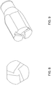
- Figs. 6 and 7 depict an alternative embodiment of the break-up tip 400.
- the break-up tip is not round, but rather has a rounded triangular shape. This is illustrative of the point that the nozzle housing and the break-up insert may take any suitable shape, so long as the pre-cursor fluids are directed around the break-up insert to the fluted channels 402 in the distal end of the break-up insert.
- the sidewall of the break-up insert 400 has a rounded portion 407 and a flat portion 409.
- a channel When placed in a nozzle housing having a cylindrical nozzle housing wall 110, a channel is formed therebetween allowing fluid to flow directly to one of the fluted channels.
- the rounded portion 407 is in a close fitting arrangement with the nozzle housing wall 110, so as to substantially eliminate any fluid flow therebetween.
- the fluted channels 402 feed into the swirl chamber 404 at acute angles to induce a swirling motion.
- Fig. 7 shows a perspective view of an exemplary break-up insert.
- Figs. 8 and 9 depict yet another alternative embodiment. This embodiment is similar to that of Figs. 6 and 7 . Notably, however, an exterior edge of each fluted channel is substantially tangential to the outer periphery of the swirl chamber. This defines an acute angle at which the fluid components enter the swirl chamber essentially driving the fluid in a spiral or swirl pattern around and into the swirl chamber causing mixing.
- Figs. 10, 11, and 12 depict yet another alternative embodiment.
- the break-up insert includes a baffle portion which is used to keep the pre-cursor fluids separate from each other until they reach the break-up tip.
- the I-like construction of the baffle provides separated conduits for each two components to flow. Any number of baffles can be used to create an appropriate number of conduits.
- the swirl chamber design is not limited to use with multi-component syringes, but may be adapted for use with any multi-lumen delivery system. For example, some systems have a longer extended delivery tip including multiple delivery lumens. These require a different nozzle, one example being depicted in Fig. 5 .
- the nozzle shape is adapted for proper coupling to the delivery lumen, but the principles of the nozzle are the same, with pre-cursor fluid being directed through a channel between the break-up insert and the housing wall, to and through a plurality of fluted channels to a swirl chamber in the distal end of the break-up insert and finally through a central exit orifice in the distal end of the housing.
- a nozzle housing, a break-up insert may be adapted for use with a three-lumen delivery device.
- the three lumen would feed into the channel defined by the nozzle housing and the break-up insert and flow into the swirl chamber via three fluted channels in the distal end of the break-up insert in a manner similar to the dual lumen system described above.
- the nozzle tips are interchangeable between multiple delivery devices, regardless of the number of lumen.
- the nozzle tip is adapted specifically for the number of lumen and the number of pre-cursor components.
- a dedicated lumen could pass through the center right to the swirl chamber for addition of another pre-cursor fluid but avoiding the other fluids entirely until at the swirl chamber. This could be used to apply a later addition of an additional component, to introduce a pulse of gas or solvent to dislodge a clogged tip or put to other use.
Landscapes
- Chemical & Material Sciences (AREA)
- Chemical Kinetics & Catalysis (AREA)
- Surgical Instruments (AREA)
Claims (10)
- Un ensemble bec de buse (100) pour mélanger de multiples fluides précurseurs (502, 504), l'ensemble bec de buse (100) comprenant :un boîtier de buse comprenantune extrémité proximale (200) conçue pour recevoir une portion de distribution d'un distributeur à lumières multiples (500) ayant au moins deux lumières pour une distribution séparée de chaque fluide précurseur (502, 504),une extrémité distale (300) définissant un orifice de sortie, etune paroi latérale (110) s'étendant de l'extrémité latérale (200) à l'extrémité distale (300) ;un insert de rupture (400) comprenantune extrémité proximale,une extrémité distale, définissant en sus au moins trois canaux cannelés (402) et une chambre de tourbillonnement centrale en renfoncement (404) etune paroi latérale (406) s'étendant entre l'extrémité proximale et l'extrémité distale,où la paroi latérale (406) de l'insert de rupture (400) et la paroi latérale (110) du boîtier de buse définissent un canal (600) entre ceux-ci s'étendant autour de la périphérie de l'insert de rupture (400) pour une communication fluidique entre les lumières et les au moins trois canaux cannelés (402) caractérisé par un déflecteur (450) s'étendant entre l'extrémité distale du distributeur à lumières et l'extrémité proximale de l'insert de rupture (400), ledit déflecteur étant configuré pour maintenir chaque fluide précurseur (502, 504) séparé l'un de l'autre avant l'insert de rupture (400).
- L'ensemble bec de buse de la revendication 1, où la chambre de tourbillonnement (404) est définie par un renfoncement semi-sphérique situé de façon substantiellement centrale dans l'extrémité distale de l'insert de rupture (400).
- L'ensemble bec de buse de la revendication 1, où chacun des canaux cannelés (402) s'approche de la chambre de tourbillonnement (404) en faisant un angle pour faciliter le mélange des fluides précurseurs (502, 504) dans la chambre de tourbillonnement (404).
- L'ensemble bec de buse de la revendication 1, où la distance entre la paroi latérale (406) de l'insert de rupture (400) et la paroi latérale (110) du boîtier de buse diminue de l'extrémité proximale à l'extrémité distale.
- L'ensemble bec de buse de la revendication 4, où l'insert de rupture (400) comprend un ou plusieurs épaulements inclinés (420) pour diminuer la distance entre la paroi latérale (406) de l'insert de rupture (400) et la paroi latérale (110) du boîtier de buse.
- L'ensemble bec de buse de la revendication 1, où les au moins trois canaux cannelés (402) sont équidistants l'un de l'autre.
- L'ensemble bec de buse de la revendication 1, où le boîtier de buse est conçu pour un couplage à une seringue à double cylindre.
- L'ensemble bec de buse de la revendication 1, où le boîtier de buse est conçu pour un couplage à un dispositif de distribution à double lumière.
- L'ensemble bec de buse de la revendication 1, où le boîtier de buse est conçu pour un couplage à un dispositif de distribution à trois lumières.
- L'ensemble bec de buse de la revendication 1, où l'ensemble bec de buse (100) est couplé à un dispositif de distribution à lumières multiples (500) de telle sorte que chacune des lumières soit en communication fluidique avec un canal défini par le déflecteur (450).
Applications Claiming Priority (2)
| Application Number | Priority Date | Filing Date | Title |
|---|---|---|---|
| US201361788311P | 2013-03-15 | 2013-03-15 | |
| PCT/US2014/028783 WO2014144393A1 (fr) | 2013-03-15 | 2014-03-14 | Buse de pulvérisation à mélange centrifuge |
Publications (3)
| Publication Number | Publication Date |
|---|---|
| EP2969159A1 EP2969159A1 (fr) | 2016-01-20 |
| EP2969159A4 EP2969159A4 (fr) | 2016-10-26 |
| EP2969159B1 true EP2969159B1 (fr) | 2019-10-02 |
Family
ID=51523233
Family Applications (1)
| Application Number | Title | Priority Date | Filing Date |
|---|---|---|---|
| EP14763389.5A Active EP2969159B1 (fr) | 2013-03-15 | 2014-03-14 | Buse de pulvérisation à mélange centrifuge |
Country Status (6)
| Country | Link |
|---|---|
| US (1) | US10144017B2 (fr) |
| EP (1) | EP2969159B1 (fr) |
| JP (1) | JP6435083B2 (fr) |
| CA (1) | CA2907204C (fr) |
| ES (1) | ES2755187T3 (fr) |
| WO (1) | WO2014144393A1 (fr) |
Families Citing this family (8)
| Publication number | Priority date | Publication date | Assignee | Title |
|---|---|---|---|---|
| RU2639773C1 (ru) * | 2017-02-27 | 2017-12-22 | Олег Савельевич Кочетов | Форсунка с коническим завихрителем |
| GB2560916B (en) * | 2017-03-27 | 2020-01-01 | Edwards Ltd | Nozzle for an abatement device |
| ES2968087T3 (es) * | 2017-04-19 | 2024-05-07 | Baxter Int | Dispositivo dispensador que no obstruye |
| RU2659966C1 (ru) * | 2017-12-19 | 2018-07-04 | Олег Савельевич Кочетов | Форсунка с коническим завихрителем |
| US11911787B1 (en) | 2019-08-16 | 2024-02-27 | Gary Hammerlund | Split manifold and method for multiple part fluid applications |
| CZ34539U1 (cs) * | 2020-09-24 | 2020-11-16 | SKALA-Medica s.r.o. | Miniinvazinní chirurgická tryska, zejména pro potřeby invazivní chirurgie |
| US11957325B2 (en) * | 2021-03-22 | 2024-04-16 | Km Biologics Co., Ltd. | Biological tissue adhesive nebulizer and clogging prevention container |
| WO2024068857A1 (fr) * | 2022-09-30 | 2024-04-04 | Ferrosan Medical Devices A/S | Applicateur de timbre pulvérisable pour arrêter des hémorragies, ensemble buse et procédé d'application d'hémostatiques chirurgicaux à un site cible |
Family Cites Families (13)
| Publication number | Priority date | Publication date | Assignee | Title |
|---|---|---|---|---|
| US4260110A (en) * | 1977-02-18 | 1981-04-07 | Winfried Werding | Spray nozzle, devices containing the same and apparatus for making such devices |
| US4923448A (en) * | 1988-12-06 | 1990-05-08 | Mark Anderson | Syringe with spray nozzle tip |
| US5116315A (en) * | 1989-10-03 | 1992-05-26 | Hemaedics, Inc. | Biological syringe system |
| ATE206078T1 (de) * | 1994-06-28 | 2001-10-15 | Aventis Behring Gmbh | Vorrichtung zum versprühen eines gemischs aus zwei komponenten |
| DE19811736A1 (de) | 1998-03-18 | 1999-09-23 | Guenter Slowik | Drallerzeuger für Düsen und Verfahren zum Verändern der Drallbewegung |
| US6921381B2 (en) * | 2001-10-05 | 2005-07-26 | Baxter International Inc. | Laparoscopic spray device and method of use |
| FR2885820B1 (fr) * | 2005-05-18 | 2007-06-22 | Rexam Dispensing Systems Sas | Buse a chambre tourbillonnaire |
| US9480543B2 (en) * | 2006-05-17 | 2016-11-01 | Medmix Systems Ag | Dispensing device with a spray assembly |
| US8408480B2 (en) | 2008-04-25 | 2013-04-02 | Confluent Surgical, Inc. | Self-cleaning spray tip |
| US8210453B2 (en) * | 2008-09-12 | 2012-07-03 | Confluent Surgical, Inc. | Spray applicator |
| US20100114158A1 (en) * | 2008-09-29 | 2010-05-06 | Nerites Corporation | Delivery assembly, delivery tip, and method of using same |
| BR112012025498A2 (pt) | 2010-04-05 | 2016-06-21 | Neomend Inc | dispositivo para liberar um composto vedante de multicomponentes, seringa de multicomponentes para liberar um composto vedante e método para liberar um composto vedante para uma ferida |
| US8672237B2 (en) * | 2010-06-25 | 2014-03-18 | Baxter International Inc. | Device for mixing and dispensing of two-component reactive surgical sealant |
-
2014
- 2014-03-14 US US14/213,162 patent/US10144017B2/en active Active
- 2014-03-14 CA CA2907204A patent/CA2907204C/fr active Active
- 2014-03-14 ES ES14763389T patent/ES2755187T3/es active Active
- 2014-03-14 JP JP2016502896A patent/JP6435083B2/ja active Active
- 2014-03-14 WO PCT/US2014/028783 patent/WO2014144393A1/fr active Application Filing
- 2014-03-14 EP EP14763389.5A patent/EP2969159B1/fr active Active
Non-Patent Citations (1)
| Title |
|---|
| None * |
Also Published As
| Publication number | Publication date |
|---|---|
| US10144017B2 (en) | 2018-12-04 |
| JP6435083B2 (ja) | 2018-12-05 |
| EP2969159A4 (fr) | 2016-10-26 |
| CA2907204A1 (fr) | 2014-09-18 |
| JP2016515408A (ja) | 2016-05-30 |
| EP2969159A1 (fr) | 2016-01-20 |
| ES2755187T3 (es) | 2020-04-21 |
| US20140263749A1 (en) | 2014-09-18 |
| CA2907204C (fr) | 2021-01-19 |
| WO2014144393A1 (fr) | 2014-09-18 |
Similar Documents
| Publication | Publication Date | Title |
|---|---|---|
| EP2969159B1 (fr) | Buse de pulvérisation à mélange centrifuge | |
| EP2584974B1 (fr) | Dispositif de mélange et de distribution d'un agent de scellement chirurgical bicomposant réactif | |
| US9125633B2 (en) | Device for mixing and dispensing of two-component reactive surgical sealant | |
| EP2111918B1 (fr) | Buse de pulvérisation en silicone | |
| EP2911775B1 (fr) | Tête de pulvérisation pour un mélangeur à deux constituants | |
| EP2895259B1 (fr) | Ensemble embout sans air et anti-obstruction et dispositif associé | |
| CN106794435B (zh) | 用于递送流体的最小阻塞装置和使用方法 | |
| EP3009194A1 (fr) | Applicateur, buse de mélange et procédé pour distribuer un melange de fluides | |
| ES2746327T3 (es) | Puntas de pulverización o goteo que tienen múltiples canales de salida | |
| US20240180538A1 (en) | Fluid mixing and delivery injector system |
Legal Events
| Date | Code | Title | Description |
|---|---|---|---|
| PUAI | Public reference made under article 153(3) epc to a published international application that has entered the european phase |
Free format text: ORIGINAL CODE: 0009012 |
|
| 17P | Request for examination filed |
Effective date: 20150921 |
|
| AK | Designated contracting states |
Kind code of ref document: A1 Designated state(s): AL AT BE BG CH CY CZ DE DK EE ES FI FR GB GR HR HU IE IS IT LI LT LU LV MC MK MT NL NO PL PT RO RS SE SI SK SM TR |
|
| AX | Request for extension of the european patent |
Extension state: BA ME |
|
| DAX | Request for extension of the european patent (deleted) | ||
| A4 | Supplementary search report drawn up and despatched |
Effective date: 20160927 |
|
| RIC1 | Information provided on ipc code assigned before grant |
Ipc: B05B 1/34 20060101ALI20160921BHEP Ipc: B01F 3/10 20060101ALI20160921BHEP Ipc: B01F 5/06 20060101AFI20160921BHEP Ipc: B01F 5/00 20060101ALI20160921BHEP Ipc: B01F 13/00 20060101ALI20160921BHEP |
|
| GRAP | Despatch of communication of intention to grant a patent |
Free format text: ORIGINAL CODE: EPIDOSNIGR1 |
|
| STAA | Information on the status of an ep patent application or granted ep patent |
Free format text: STATUS: GRANT OF PATENT IS INTENDED |
|
| INTG | Intention to grant announced |
Effective date: 20190415 |
|
| GRAS | Grant fee paid |
Free format text: ORIGINAL CODE: EPIDOSNIGR3 |
|
| GRAA | (expected) grant |
Free format text: ORIGINAL CODE: 0009210 |
|
| STAA | Information on the status of an ep patent application or granted ep patent |
Free format text: STATUS: THE PATENT HAS BEEN GRANTED |
|
| AK | Designated contracting states |
Kind code of ref document: B1 Designated state(s): AL AT BE BG CH CY CZ DE DK EE ES FI FR GB GR HR HU IE IS IT LI LT LU LV MC MK MT NL NO PL PT RO RS SE SI SK SM TR |
|
| REG | Reference to a national code |
Ref country code: GB Ref legal event code: FG4D |
|
| REG | Reference to a national code |
Ref country code: CH Ref legal event code: EP Ref country code: AT Ref legal event code: REF Ref document number: 1185577 Country of ref document: AT Kind code of ref document: T Effective date: 20191015 |
|
| REG | Reference to a national code |
Ref country code: DE Ref legal event code: R096 Ref document number: 602014054590 Country of ref document: DE |
|
| REG | Reference to a national code |
Ref country code: IE Ref legal event code: FG4D |
|
| REG | Reference to a national code |
Ref country code: NL Ref legal event code: MP Effective date: 20191002 |
|
| REG | Reference to a national code |
Ref country code: LT Ref legal event code: MG4D |
|
| REG | Reference to a national code |
Ref country code: AT Ref legal event code: MK05 Ref document number: 1185577 Country of ref document: AT Kind code of ref document: T Effective date: 20191002 |
|
| REG | Reference to a national code |
Ref country code: ES Ref legal event code: FG2A Ref document number: 2755187 Country of ref document: ES Kind code of ref document: T3 Effective date: 20200421 |
|
| PG25 | Lapsed in a contracting state [announced via postgrant information from national office to epo] |
Ref country code: PL Free format text: LAPSE BECAUSE OF FAILURE TO SUBMIT A TRANSLATION OF THE DESCRIPTION OR TO PAY THE FEE WITHIN THE PRESCRIBED TIME-LIMIT Effective date: 20191002 Ref country code: AT Free format text: LAPSE BECAUSE OF FAILURE TO SUBMIT A TRANSLATION OF THE DESCRIPTION OR TO PAY THE FEE WITHIN THE PRESCRIBED TIME-LIMIT Effective date: 20191002 Ref country code: NL Free format text: LAPSE BECAUSE OF FAILURE TO SUBMIT A TRANSLATION OF THE DESCRIPTION OR TO PAY THE FEE WITHIN THE PRESCRIBED TIME-LIMIT Effective date: 20191002 Ref country code: SE Free format text: LAPSE BECAUSE OF FAILURE TO SUBMIT A TRANSLATION OF THE DESCRIPTION OR TO PAY THE FEE WITHIN THE PRESCRIBED TIME-LIMIT Effective date: 20191002 Ref country code: NO Free format text: LAPSE BECAUSE OF FAILURE TO SUBMIT A TRANSLATION OF THE DESCRIPTION OR TO PAY THE FEE WITHIN THE PRESCRIBED TIME-LIMIT Effective date: 20200102 Ref country code: LV Free format text: LAPSE BECAUSE OF FAILURE TO SUBMIT A TRANSLATION OF THE DESCRIPTION OR TO PAY THE FEE WITHIN THE PRESCRIBED TIME-LIMIT Effective date: 20191002 Ref country code: GR Free format text: LAPSE BECAUSE OF FAILURE TO SUBMIT A TRANSLATION OF THE DESCRIPTION OR TO PAY THE FEE WITHIN THE PRESCRIBED TIME-LIMIT Effective date: 20200103 Ref country code: LT Free format text: LAPSE BECAUSE OF FAILURE TO SUBMIT A TRANSLATION OF THE DESCRIPTION OR TO PAY THE FEE WITHIN THE PRESCRIBED TIME-LIMIT Effective date: 20191002 Ref country code: FI Free format text: LAPSE BECAUSE OF FAILURE TO SUBMIT A TRANSLATION OF THE DESCRIPTION OR TO PAY THE FEE WITHIN THE PRESCRIBED TIME-LIMIT Effective date: 20191002 Ref country code: BG Free format text: LAPSE BECAUSE OF FAILURE TO SUBMIT A TRANSLATION OF THE DESCRIPTION OR TO PAY THE FEE WITHIN THE PRESCRIBED TIME-LIMIT Effective date: 20200102 Ref country code: PT Free format text: LAPSE BECAUSE OF FAILURE TO SUBMIT A TRANSLATION OF THE DESCRIPTION OR TO PAY THE FEE WITHIN THE PRESCRIBED TIME-LIMIT Effective date: 20200203 |
|
| PG25 | Lapsed in a contracting state [announced via postgrant information from national office to epo] |
Ref country code: IS Free format text: LAPSE BECAUSE OF FAILURE TO SUBMIT A TRANSLATION OF THE DESCRIPTION OR TO PAY THE FEE WITHIN THE PRESCRIBED TIME-LIMIT Effective date: 20200224 Ref country code: RS Free format text: LAPSE BECAUSE OF FAILURE TO SUBMIT A TRANSLATION OF THE DESCRIPTION OR TO PAY THE FEE WITHIN THE PRESCRIBED TIME-LIMIT Effective date: 20191002 Ref country code: CZ Free format text: LAPSE BECAUSE OF FAILURE TO SUBMIT A TRANSLATION OF THE DESCRIPTION OR TO PAY THE FEE WITHIN THE PRESCRIBED TIME-LIMIT Effective date: 20191002 Ref country code: HR Free format text: LAPSE BECAUSE OF FAILURE TO SUBMIT A TRANSLATION OF THE DESCRIPTION OR TO PAY THE FEE WITHIN THE PRESCRIBED TIME-LIMIT Effective date: 20191002 |
|
| PG25 | Lapsed in a contracting state [announced via postgrant information from national office to epo] |
Ref country code: AL Free format text: LAPSE BECAUSE OF FAILURE TO SUBMIT A TRANSLATION OF THE DESCRIPTION OR TO PAY THE FEE WITHIN THE PRESCRIBED TIME-LIMIT Effective date: 20191002 |
|
| REG | Reference to a national code |
Ref country code: DE Ref legal event code: R097 Ref document number: 602014054590 Country of ref document: DE |
|
| PG2D | Information on lapse in contracting state deleted |
Ref country code: IS |
|
| PG25 | Lapsed in a contracting state [announced via postgrant information from national office to epo] |
Ref country code: EE Free format text: LAPSE BECAUSE OF FAILURE TO SUBMIT A TRANSLATION OF THE DESCRIPTION OR TO PAY THE FEE WITHIN THE PRESCRIBED TIME-LIMIT Effective date: 20191002 Ref country code: DK Free format text: LAPSE BECAUSE OF FAILURE TO SUBMIT A TRANSLATION OF THE DESCRIPTION OR TO PAY THE FEE WITHIN THE PRESCRIBED TIME-LIMIT Effective date: 20191002 Ref country code: RO Free format text: LAPSE BECAUSE OF FAILURE TO SUBMIT A TRANSLATION OF THE DESCRIPTION OR TO PAY THE FEE WITHIN THE PRESCRIBED TIME-LIMIT Effective date: 20191002 Ref country code: IS Free format text: LAPSE BECAUSE OF FAILURE TO SUBMIT A TRANSLATION OF THE DESCRIPTION OR TO PAY THE FEE WITHIN THE PRESCRIBED TIME-LIMIT Effective date: 20200202 |
|
| PLBE | No opposition filed within time limit |
Free format text: ORIGINAL CODE: 0009261 |
|
| STAA | Information on the status of an ep patent application or granted ep patent |
Free format text: STATUS: NO OPPOSITION FILED WITHIN TIME LIMIT |
|
| PG25 | Lapsed in a contracting state [announced via postgrant information from national office to epo] |
Ref country code: SK Free format text: LAPSE BECAUSE OF FAILURE TO SUBMIT A TRANSLATION OF THE DESCRIPTION OR TO PAY THE FEE WITHIN THE PRESCRIBED TIME-LIMIT Effective date: 20191002 Ref country code: SM Free format text: LAPSE BECAUSE OF FAILURE TO SUBMIT A TRANSLATION OF THE DESCRIPTION OR TO PAY THE FEE WITHIN THE PRESCRIBED TIME-LIMIT Effective date: 20191002 |
|
| 26N | No opposition filed |
Effective date: 20200703 |
|
| PG25 | Lapsed in a contracting state [announced via postgrant information from national office to epo] |
Ref country code: MC Free format text: LAPSE BECAUSE OF FAILURE TO SUBMIT A TRANSLATION OF THE DESCRIPTION OR TO PAY THE FEE WITHIN THE PRESCRIBED TIME-LIMIT Effective date: 20191002 |
|
| REG | Reference to a national code |
Ref country code: CH Ref legal event code: PL |
|
| PG25 | Lapsed in a contracting state [announced via postgrant information from national office to epo] |
Ref country code: SI Free format text: LAPSE BECAUSE OF FAILURE TO SUBMIT A TRANSLATION OF THE DESCRIPTION OR TO PAY THE FEE WITHIN THE PRESCRIBED TIME-LIMIT Effective date: 20191002 |
|
| REG | Reference to a national code |
Ref country code: BE Ref legal event code: MM Effective date: 20200331 |
|
| PG25 | Lapsed in a contracting state [announced via postgrant information from national office to epo] |
Ref country code: LU Free format text: LAPSE BECAUSE OF NON-PAYMENT OF DUE FEES Effective date: 20200314 |
|
| PG25 | Lapsed in a contracting state [announced via postgrant information from national office to epo] |
Ref country code: LI Free format text: LAPSE BECAUSE OF NON-PAYMENT OF DUE FEES Effective date: 20200331 Ref country code: CH Free format text: LAPSE BECAUSE OF NON-PAYMENT OF DUE FEES Effective date: 20200331 Ref country code: IE Free format text: LAPSE BECAUSE OF NON-PAYMENT OF DUE FEES Effective date: 20200314 |
|
| PG25 | Lapsed in a contracting state [announced via postgrant information from national office to epo] |
Ref country code: BE Free format text: LAPSE BECAUSE OF NON-PAYMENT OF DUE FEES Effective date: 20200331 |
|
| REG | Reference to a national code |
Ref country code: DE Ref legal event code: R079 Ref document number: 602014054590 Country of ref document: DE Free format text: PREVIOUS MAIN CLASS: B01F0005060000 Ipc: B01F0025400000 |
|
| PG25 | Lapsed in a contracting state [announced via postgrant information from national office to epo] |
Ref country code: TR Free format text: LAPSE BECAUSE OF FAILURE TO SUBMIT A TRANSLATION OF THE DESCRIPTION OR TO PAY THE FEE WITHIN THE PRESCRIBED TIME-LIMIT Effective date: 20191002 Ref country code: MT Free format text: LAPSE BECAUSE OF FAILURE TO SUBMIT A TRANSLATION OF THE DESCRIPTION OR TO PAY THE FEE WITHIN THE PRESCRIBED TIME-LIMIT Effective date: 20191002 Ref country code: CY Free format text: LAPSE BECAUSE OF FAILURE TO SUBMIT A TRANSLATION OF THE DESCRIPTION OR TO PAY THE FEE WITHIN THE PRESCRIBED TIME-LIMIT Effective date: 20191002 |
|
| PG25 | Lapsed in a contracting state [announced via postgrant information from national office to epo] |
Ref country code: MK Free format text: LAPSE BECAUSE OF FAILURE TO SUBMIT A TRANSLATION OF THE DESCRIPTION OR TO PAY THE FEE WITHIN THE PRESCRIBED TIME-LIMIT Effective date: 20191002 |
|
| PGFP | Annual fee paid to national office [announced via postgrant information from national office to epo] |
Ref country code: FR Payment date: 20230222 Year of fee payment: 10 |
|
| PGFP | Annual fee paid to national office [announced via postgrant information from national office to epo] |
Ref country code: IT Payment date: 20230221 Year of fee payment: 10 |
|
| PGFP | Annual fee paid to national office [announced via postgrant information from national office to epo] |
Ref country code: ES Payment date: 20230403 Year of fee payment: 10 |
|
| PGFP | Annual fee paid to national office [announced via postgrant information from national office to epo] |
Ref country code: DE Payment date: 20240220 Year of fee payment: 11 Ref country code: GB Payment date: 20240221 Year of fee payment: 11 |