EP2555183A2 - Unité de rétroéclairage et procédé de commande de DEL - Google Patents
Unité de rétroéclairage et procédé de commande de DEL Download PDFInfo
- Publication number
- EP2555183A2 EP2555183A2 EP20120161858 EP12161858A EP2555183A2 EP 2555183 A2 EP2555183 A2 EP 2555183A2 EP 20120161858 EP20120161858 EP 20120161858 EP 12161858 A EP12161858 A EP 12161858A EP 2555183 A2 EP2555183 A2 EP 2555183A2
- Authority
- EP
- European Patent Office
- Prior art keywords
- led
- unit
- temperature
- voltage
- driving
- Prior art date
- Legal status (The legal status is an assumption and is not a legal conclusion. Google has not performed a legal analysis and makes no representation as to the accuracy of the status listed.)
- Withdrawn
Links
- 238000000034 method Methods 0.000 title claims description 16
- 238000010586 diagram Methods 0.000 description 16
- 238000013021 overheating Methods 0.000 description 9
- 230000003247 decreasing effect Effects 0.000 description 6
- 238000001514 detection method Methods 0.000 description 2
- 239000011521 glass Substances 0.000 description 2
- 230000002265 prevention Effects 0.000 description 2
- 238000006243 chemical reaction Methods 0.000 description 1
- 238000010276 construction Methods 0.000 description 1
- 238000005259 measurement Methods 0.000 description 1
Images


Classifications
-
- G—PHYSICS
- G09—EDUCATION; CRYPTOGRAPHY; DISPLAY; ADVERTISING; SEALS
- G09G—ARRANGEMENTS OR CIRCUITS FOR CONTROL OF INDICATING DEVICES USING STATIC MEANS TO PRESENT VARIABLE INFORMATION
- G09G3/00—Control arrangements or circuits, of interest only in connection with visual indicators other than cathode-ray tubes
- G09G3/20—Control arrangements or circuits, of interest only in connection with visual indicators other than cathode-ray tubes for presentation of an assembly of a number of characters, e.g. a page, by composing the assembly by combination of individual elements arranged in a matrix no fixed position being assigned to or needed to be assigned to the individual characters or partial characters
- G09G3/34—Control arrangements or circuits, of interest only in connection with visual indicators other than cathode-ray tubes for presentation of an assembly of a number of characters, e.g. a page, by composing the assembly by combination of individual elements arranged in a matrix no fixed position being assigned to or needed to be assigned to the individual characters or partial characters by control of light from an independent source
- G09G3/3406—Control of illumination source
-
- H—ELECTRICITY
- H05—ELECTRIC TECHNIQUES NOT OTHERWISE PROVIDED FOR
- H05B—ELECTRIC HEATING; ELECTRIC LIGHT SOURCES NOT OTHERWISE PROVIDED FOR; CIRCUIT ARRANGEMENTS FOR ELECTRIC LIGHT SOURCES, IN GENERAL
- H05B45/00—Circuit arrangements for operating light-emitting diodes [LED]
- H05B45/30—Driver circuits
- H05B45/37—Converter circuits
- H05B45/3725—Switched mode power supply [SMPS]
- H05B45/38—Switched mode power supply [SMPS] using boost topology
-
- H—ELECTRICITY
- H05—ELECTRIC TECHNIQUES NOT OTHERWISE PROVIDED FOR
- H05B—ELECTRIC HEATING; ELECTRIC LIGHT SOURCES NOT OTHERWISE PROVIDED FOR; CIRCUIT ARRANGEMENTS FOR ELECTRIC LIGHT SOURCES, IN GENERAL
- H05B45/00—Circuit arrangements for operating light-emitting diodes [LED]
- H05B45/50—Circuit arrangements for operating light-emitting diodes [LED] responsive to malfunctions or undesirable behaviour of LEDs; responsive to LED life; Protective circuits
- H05B45/56—Circuit arrangements for operating light-emitting diodes [LED] responsive to malfunctions or undesirable behaviour of LEDs; responsive to LED life; Protective circuits involving measures to prevent abnormal temperature of the LEDs
-
- H—ELECTRICITY
- H05—ELECTRIC TECHNIQUES NOT OTHERWISE PROVIDED FOR
- H05B—ELECTRIC HEATING; ELECTRIC LIGHT SOURCES NOT OTHERWISE PROVIDED FOR; CIRCUIT ARRANGEMENTS FOR ELECTRIC LIGHT SOURCES, IN GENERAL
- H05B47/00—Circuit arrangements for operating light sources in general, i.e. where the type of light source is not relevant
- H05B47/20—Responsive to malfunctions or to light source life; for protection
- H05B47/28—Circuit arrangements for protecting against abnormal temperature
-
- G—PHYSICS
- G09—EDUCATION; CRYPTOGRAPHY; DISPLAY; ADVERTISING; SEALS
- G09G—ARRANGEMENTS OR CIRCUITS FOR CONTROL OF INDICATING DEVICES USING STATIC MEANS TO PRESENT VARIABLE INFORMATION
- G09G2320/00—Control of display operating conditions
- G09G2320/04—Maintaining the quality of display appearance
- G09G2320/041—Temperature compensation
-
- G—PHYSICS
- G09—EDUCATION; CRYPTOGRAPHY; DISPLAY; ADVERTISING; SEALS
- G09G—ARRANGEMENTS OR CIRCUITS FOR CONTROL OF INDICATING DEVICES USING STATIC MEANS TO PRESENT VARIABLE INFORMATION
- G09G2330/00—Aspects of power supply; Aspects of display protection and defect management
- G09G2330/04—Display protection
- G09G2330/045—Protection against panel overheating
-
- H—ELECTRICITY
- H05—ELECTRIC TECHNIQUES NOT OTHERWISE PROVIDED FOR
- H05B—ELECTRIC HEATING; ELECTRIC LIGHT SOURCES NOT OTHERWISE PROVIDED FOR; CIRCUIT ARRANGEMENTS FOR ELECTRIC LIGHT SOURCES, IN GENERAL
- H05B45/00—Circuit arrangements for operating light-emitting diodes [LED]
- H05B45/30—Driver circuits
- H05B45/37—Converter circuits
- H05B45/3725—Switched mode power supply [SMPS]
- H05B45/375—Switched mode power supply [SMPS] using buck topology
Definitions
- the present invention relates to a backlight unit and a method for controlling an LED, and more particularly to a backlight unit and a method for controlling an LED, which can prevent overheating through sensing of an internal temperature of an LED driving circuit.
- a shutter glasses type 3D LED backlight display alternately displays a left-eye image and a right-eye image on a screen.
- Shutter glasses alternately transmit/intercept a left-eye image and a right-eye image in synchronization with an image that is alternately displayed to realize a 3D image.
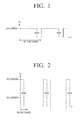
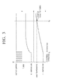
- a backlight is driven with current having a reduced duty cycle in synchronization with the image. If the duty cycle is reduced as described above, luminance of a display is decreased. Accordingly, in order to compensate for the decrease of luminance, a 3D current having a peak value that is several times higher than a peak value of a 2D normal current is used.
- the maximum duty cycle of on time range of the 3D current illustrated in FIG. 2 is limited in comparison to the maximum duty cycle of on time range of the 2D current illustrated in FIG. 1 .
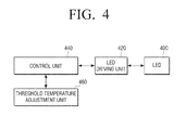
- FIG. 3 is a diagram explaining the occurrence of fuming due to 3D current overload in a 3D mode. Referring to FIG. 3 , the occurrence of fuming in respective elements of an LED driving circuit due to 3D current overload will be examined as follows.
- a 3D overload occurs due to an error of a driving circuit or other systems at time t s .
- the temperature of an integrated circuit (IC) is increased from the overload occurrence time t s .
- the temperature (L temperature) of an inductor that is an element of the LED driving circuit is increased.
- the inductor starts fuming.
- the threshold temperature Tjmax of the integrated circuit is much higher than the limit temperature of the inductor, overheating prevention function in the integrated circuit does not operate, and thus a control unit is unable to control the operation of the LED driving circuit.
- OTP Over-Temperature Protection
- a backlight unit and a method for controlling an LED which can prevent overheating of an LED driving circuit through detection of an internal temperature of the LED driving circuit.
- An exemplary embodiment of the present invention provides a backlight unit which includes an LED; an LED driving unit driving the LED; a control unit measuring a temperature of the LED driving unit and if the temperature exceeds a preset threshold temperature, interrupting an operation of the LED driving unit; and a threshold temperature adjustment unit changing the threshold temperature on the basis of limit temperatures of circuit elements included in the LED driving unit.
- the LED driving unit may include a DC-DC converter converting an input voltage into an LED driving voltage according to an operation of a transistor that is controlled by the control unit and providing the LED driving voltage to the LED.
- the control unit may include a resistor unit having a resistance value that is changed according to the temperature of the LED driving unit; and a comparator unit comparing a voltage value of the resistor unit with a reference voltage, and if the voltage value exceeds the reference voltage, outputting a control signal for turning off the transistor.
- the threshold temperature adjustment unit may include a voltmeter providing a voltage that corresponds to a minimum temperature among limit temperatures of the circuit elements to the comparator unit as the reference voltage.
- the threshold temperature adjustment unit may include a plurality of resistors connected in series; a plurality of switches arranged between connection nodes between the plurality of resistors and a reference voltage input terminal of the comparator unit; and an adjustment unit adjusting the reference voltage through control of on/off operations of the switches according to a user selection.
- Another exemplary embodiment of the present invention provides a method for driving an LED which includes converting an input voltage into an LED driving voltage and driving the LED; and measuring a temperature of a driving circuit that drives the LED, and if the temperature exceeds a threshold temperature, interrupting an operation of the driving circuit; wherein the threshold temperature is a changeable temperature on the basis of limit temperatures of circuit elements included in the driving circuit.
- the interrupting step may include detecting a voltage value of a resistor having a resistance value that is changed according to a temperature of the driving circuit; and comparing the voltage value of the resistor with a reference voltage, and if the voltage value exceeds the reference voltage, turning off a transistor that drives the driving circuit.
- the reference voltage may be a voltage which corresponds to a minimum temperature among the limit temperatures of the circuit elements, and may be provided from a voltmeter connected to a comparator that compares the voltage value of the resistor with the reference voltage.
- overheating of the whole elements of the LED driving circuit can be prevented through measurement of an internal temperature of the LED driving circuit.
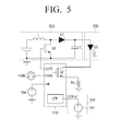
- FIG. 4 is a block diagram illustrating the configuration of a backlight unit according to an embodiment of the present invention.
- a backlight unit includes an LED 400, an LED driving unit 420, a control unit 440, and a threshold temperature adjustment unit 460.
- the LED 400 receives a driving signal and power from the LED driving unit 420, and emits light according to the driving signal.
- the LED driving unit 420 is controlled by the control unit 440 to supply the driving signal and the power to the LED 400.
- the LED driving unit 420 is controlled by the control unit 440. That is, the control unit 440 controls a switch that performs a switch operation in the LED driving unit 420.
- a DC-DC converter converts an input voltage into a power for driving the LED, and provides the power to the LED 400.
- the control unit 440 functions to interrupt the operation of the LED driving unit 420 if an internal temperature of the LED driving circuit 420 exceeds a preset threshold temperature.
- control unit 440 includes a resistor unit (not illustrated) having a resistance value that is changed according to the temperature of the LED driving unit 420, and a comparator unit (not illustrated) comparing a voltage value of the resistor unit with a reference voltage, and if the voltage value exceeds the reference voltage, outputting a control signal for turning on/off the transistor.
- the resistor unit may be implemented by a P-N junction diode of which the resistance value is changed according to the change of temperature.
- the comparator unit may be implemented by, but is not limited to, an operational amplifier Op-Amp that can compare two input voltages.
- the comparator unit compares the voltage value of the resistor unit with the reference voltage value, and if the voltage value of the resistor unit exceeds the reference value, it outputs the control signal for turning off the transistor.
- the transistor is turned off, the internal current of the LED driving circuit and the LED is reduced. If the current that flows through the LED 400 is reduced, the overheating of the LED driving circuit 420 can be prevented.
- the threshold temperature adjustment unit 460 may change the threshold temperature of the control unit 440 on the basis of limit temperatures of the circuit elements included in the LED driving unit 520.
- the preset threshold temperature of the control unit 440 is much higher than that of the circuit elements included in the LED driving unit 420. If the control unit 440 is operable at the preset threshold temperature, the control unit 440 does not operate even at a temperature that exceeds the limit temperature of the circuit elements of the LED driving unit 420, and thus the circuit elements of the LED driving unit 420 may be damaged due to the overheating.
- the threshold temperature adjustment unit 460 adjusts the preset threshold temperature of the control unit 440 to the limit temperatures of the elements included in the LED driving unit 420. As described above, the preset threshold temperature is much higher than the limit temperatures of the respective elements included in the LED driving unit 420. If the threshold temperature of the control unit 440 is adjusted to the limit temperature, the control unit 440 can start the operation at a temperature that is lower than the preset threshold value, and thus the elements included in the LED driving unit 420 can be protected at the lower temperature.
- FIG. 5 is a diagram illustrating a more detailed configuration of a backlight unit according to an embodiment of the present invention.
- the backlight unit includes an LED 500, an LED driving unit 520, a control unit 540, and a threshold temperature adjustment unit 560.
- the LED 500 receives a driving signal and power from the LED driving unit 520. If the LED 500 is driven, the temperature of the LED driving unit 520 is increased.
- the LED driving unit 520 may include a DC-DC converter and a switch element.
- the DC-DC converter performs conversion of DC power and supplies the converted power to the LED D2.
- the switch element may be implemented by a first transistor Q1 that is driven based on the ground to realize an LED backlight driving waveform, and thus it is possible to turn on/off the current at high speed with convenience in operation.
- the control unit 540 controls the operation of the LED D2 through control of the DC-DC converter through the switch element Q1.
- the control unit 540 detects the temperature of the LED driving unit 520.
- the control unit 540 may include a temperature sensor installed therein or may detect the temperature of the LED driving unit 620 using a temperature sensor installed outside the control unit 540.
- control unit 540 may include an OTP (Over-Temperature Protection) and a second transistor Q2.
- the OTP performs over-temperature protection for protecting the integrated circuit from being damaged when the internal temperature of the integrated circuit exceeds the threshold temperature and thus the integrated circuit is overheated.
- the OTP operates if overload is applied to a gate terminal due to the damage of the first transistor Q1 or overcurrent flows to the second transistor Q2 due to the damage of the LED D2 or the like.
- the second transistor Q2 is an element that performs PWM dimming by turning on/off the LED current. Since the second transistor Q2 requires capacitance that is in proportion to the current output to the LED D2, unlike the first transistor Q1 that requires capacitance that is in proportion to the power output to the LED D2, it has slight limitation in design according to its applications, and thus can be easily integrated in the inside of the control unit 540 to realize the integrated circuit as illustrated in FIG. 5 .
- the current that flows through the LED D2 passes through the second transistor Q2 and flows to ground through an output resistor Ro.
- the current, which flows through the LED D2 and is sensed by the output resistor Ro is compared with the reference value Iref inside the control unit 540, and by a gate output that is generated according to the result of the comparison, the duty cycle of the first transistor Q1 is varied, so that the current that is sensed by the output resistor Ro is controlled to follow the reference value Iref.
- a PDIM terminal of the control unit 540 is a terminal that receives the PWM dimming signal.
- the second transistor Q2 is turned on/off to perform the PWM dimming.
- boost type 3D LED driving circuit is representatively illustrated in FIG. 5
- the LED driving circuit is not limited thereto.
- Other types of circuits such as buck or buck-boost type circuits may be used instead.
- the second transistor Q2 of FIG. 5 is merely turned on/off according to the PDIM signal as described above, it can be implemented as an element that can directly control the current flowing to the LED through fine control of the gate voltage.
- the first transistor Q1 is not adjusted to control the current of the LED D2, but may be adjusted to control a special voltage or the voltage at both ends of the second transistor Q2.
- the threshold temperature adjustment unit 560 compares the detected temperature of the LED driving unit 520 with the limit temperatures of the respective elements included in the LED driving unit 520.
- the threshold temperature adjustment unit 560 changes the preset threshold temperature of the control unit 540 to the limit temperature.
- the threshold temperature adjustment unit 560 may be implemented by a voltage setting means or voltmeter 561.
- the voltmeter 561 provides the voltage, or enables the voltage to be set, that corresponds to the minimum temperature among the limit temperatures of the respective circuit elements included in the LED driving unit 520 as the reference voltage.
- the threshold temperature adjustment unit 560 may be implemented by a current meter in addition to the voltmeter. Further, the threshold temperature adjustment unit 560 may be implemented by a means for changing a current value and a voltage value from the outside by a user.
- the threshold temperature adjustment unit 560 inputs the voltage that corresponds to the minimum temperature among the limit temperatures of the circuit elements included in the LED driving unit 520 to the control unit 540 as the reference voltage (OTPset).
- the preset threshold temperature of the control unit 540 is changed to a new threshold temperature that corresponds to the different reference voltage.
- the new threshold temperature becomes the minimum temperature among the limit temperatures of the circuit elements included in the LED driving unit 520.
- the control unit 540 compares the newly set threshold temperature with the internal temperature of the LED driving unit 520, and if the newly set threshold temperature exceeds the internal temperature, it controls the operation of the LED driving unit 520 to prevent the respective elements of the LED driving unit 520 from being overheated.
- the control unit 540 starts its operation to control the operation of the LED driving unit 520, and thus the circuit elements included in the LED driving unit 520 can be prevented from being overheated.
- the threshold temperature adjustment unit 560 may be configured to include an adjustment unit that adjusts reference voltage through on/off control of a plurality of resistors connected in series, a plurality of switches arranged between the connection nodes of the resistors and the reference voltage input terminal of the comparator unit, or a plurality of switches according to the user selection.
- FIG. 6 is a diagram illustrating a method for controlling an LED according to another embodiment of the present invention.
- the method for controlling an LED may include driving an LED (S600), comparing the temperature of the LED driving circuit with a preset threshold temperature (S620), and interrupting an operation of the driving circuit (S640).
- the step of driving the LED (S600) converts the input power into an LED driving power to operate the LED.
- the step of comparing the internal temperature of the LED driving circuit with the threshold temperature measures the internal temperature of the LED driving circuit that is generated through the operation of the LED, and determines whether the measured internal temperature exceeds the threshold temperature.
- the step of interrupting the operation of the driving circuit interrupts the operation of the LED driving circuit if the measured internal temperature exceeds the threshold temperature ("Y" in S620).
- the threshold temperature is a temperature that is changeable on the basis of the respective limit temperatures of the circuit elements included in the LED driving circuit.
- FIG. 7 is a diagram illustrating in detail the method for controlling an LED according to another embodiment of the present invention.
- the method for controlling an LED includes driving an LED (S710), comparing the voltage value with the reference value (S730), and turning on/off a driving transistor (S750).
- the step of driving an LED applies the driving signal and the power to the LED to operate the LED.
- the step of comparing the voltage value with the reference voltage (S730) further performs detection of a voltage value of a resistor having a resistance value that is changed according to the temperature of the LED driving circuit.
- the detected voltage value corresponds to the temperature of the inside of the LED driving circuit.
- the detected voltage value is compared with the reference value. This means comparing of the internal temperature of the LED driving unit with the threshold temperature.
- the step of turning on/off the driving transistor (S750) turns off the transistor that drives the LED driving circuit if the voltage value exceeds the reference voltage.
- the reference voltage is a voltage that corresponds to the minimum temperature among the limit temperatures of the circuit elements, and is provided to be compared with the voltage value of the resistor.
- the driving transistor is turned off to decrease the current that flows to the LED.
- the internal temperature of the LED driving circuit is decreased.
- the control unit turns on the driving transistor and thus the current that flows to the LED is increased.
- control unit If it is determined that the voltage value of the resistor exceeds the reference voltage ("Y" in S700), the control unit operates to interrupt the current that flows to the LED or to increase the current that flows through the LED again after a predetermined time elapses.
- FIG. 8 is a diagram explaining the control of an LED temperature according to an embodiment of the present invention.
- 3D current operates normally.
- L temperature the temperature of the inductor
- IC temperature the temperature of the integrated circuit
- the control unit Since the IC temperature does not reach the preset threshold temperature Tjmax of the integrated circuit, the control unit does not operate. If it is determined that the internal temperature of the LED driving unit is higher than the minimum limit temperatures of the respective elements, the threshold temperature adjustment unit sets the reference voltage that corresponds to the internal temperature as a new reference voltage of the control unit.
- the control unit operates at a time t 2 when the new reference voltage is set to control the operation of the LED driving unit, and thus the driving of the LED is stopped or the current that flows to the LED is decreased.
- the temperature of the integrated circuit is decreased.
- the temperature of the inductor that is one of the elements of the LED driving unit is decreased.
- the operation of the LED driving unit may be controlled so that the IC temperature and the L temperature continue to be decreased.
- the control unit controls the operation of the LED driving unit again to drive the LED or to increase the current that flows to the LED.
- the control unit starts or stops the control operation.
- the present invention can be applied to a backlight unit and can be implemented by one modularized integrated circuit to be applied to various kinds of circuit overheating prevention devices.
Applications Claiming Priority (1)
| Application Number | Priority Date | Filing Date | Title |
|---|---|---|---|
| KR1020110077872A KR20130015714A (ko) | 2011-08-04 | 2011-08-04 | 백라이트 유닛 및 led 제어방법 |
Publications (2)
| Publication Number | Publication Date |
|---|---|
| EP2555183A2 true EP2555183A2 (fr) | 2013-02-06 |
| EP2555183A3 EP2555183A3 (fr) | 2013-02-20 |
Family
ID=46084755
Family Applications (1)
| Application Number | Title | Priority Date | Filing Date |
|---|---|---|---|
| EP20120161858 Withdrawn EP2555183A3 (fr) | 2011-08-04 | 2012-03-28 | Unité de rétroéclairage et procédé de commande de DEL |
Country Status (3)
| Country | Link |
|---|---|
| US (1) | US8890443B2 (fr) |
| EP (1) | EP2555183A3 (fr) |
| KR (1) | KR20130015714A (fr) |
Cited By (1)
| Publication number | Priority date | Publication date | Assignee | Title |
|---|---|---|---|---|
| EP3447757A1 (fr) * | 2017-08-23 | 2019-02-27 | Vestel Elektronik Sanayi ve Ticaret A.S. | Dispositif d'affichage et son procédé de fabrication |
Families Citing this family (13)
| Publication number | Priority date | Publication date | Assignee | Title |
|---|---|---|---|---|
| US9060408B2 (en) * | 2012-07-10 | 2015-06-16 | Dialog Semiconductor Inc. | Thermal de-rating power supply for LED loads |
| CN105009193B (zh) * | 2013-03-08 | 2019-01-11 | 杜比实验室特许公司 | 用于具有光转换的双调制显示器的技术 |
| US9265119B2 (en) | 2013-06-17 | 2016-02-16 | Terralux, Inc. | Systems and methods for providing thermal fold-back to LED lights |
| US9489898B2 (en) * | 2013-12-06 | 2016-11-08 | Shenzhen China Star Optoelectronics Technology Co., Ltd. | LED boost converter and backlight LED driver device using the same |
| CN103680444B (zh) * | 2013-12-06 | 2016-03-30 | 深圳市华星光电技术有限公司 | Led升压转换器及应用其的背光源led驱动装置 |
| CN104807557A (zh) * | 2014-01-29 | 2015-07-29 | 中强光电股份有限公司 | 温度检测器以及使用该温度检测器的投影机 |
| US9603206B2 (en) * | 2015-02-27 | 2017-03-21 | Cirrus Logic, Inc. | Detection and control mechanism for tail current in a bipolar junction transistor (BJT)-based power stage |
| CN108538258B (zh) * | 2017-03-06 | 2023-03-24 | 北京小米移动软件有限公司 | 调整背光电流的方法及装置、显示设备 |
| CN108091311B (zh) * | 2017-12-29 | 2020-12-08 | 武汉华显光电技术有限公司 | 显示模组的控制方法、显示模组、终端及存储介质 |
| US11170685B2 (en) * | 2020-04-01 | 2021-11-09 | Novatek Microelectronics Corp. | Display device and driving device thereof |
| KR20220013140A (ko) * | 2020-07-24 | 2022-02-04 | 삼성전자주식회사 | 디스플레이장치 및 그 제어방법 |
| CN111933070A (zh) * | 2020-07-27 | 2020-11-13 | 重庆惠科金渝光电科技有限公司 | 驱动电路以及显示装置 |
| JP2022190232A (ja) * | 2021-06-14 | 2022-12-26 | 株式会社ミツトヨ | 照明装置 |
Family Cites Families (10)
| Publication number | Priority date | Publication date | Assignee | Title |
|---|---|---|---|---|
| JP3942387B2 (ja) * | 2001-02-13 | 2007-07-11 | 株式会社小糸製作所 | 放電灯点灯回路 |
| US6982528B2 (en) * | 2003-11-12 | 2006-01-03 | Lutron Electronics Co., Inc. | Thermal protection for lamp ballasts |
| JP4564363B2 (ja) | 2005-01-13 | 2010-10-20 | パナソニック株式会社 | Led駆動用半導体装置及びled駆動装置 |
| JP4535383B2 (ja) * | 2005-07-20 | 2010-09-01 | 株式会社小糸製作所 | 車両用灯具の点灯制御装置 |
| US20070132709A1 (en) * | 2005-12-12 | 2007-06-14 | Toshiba Matsushita Display Technology Co., Ltd | Liquid crystal display device and method for driving the same |
| TW200737070A (en) | 2006-02-23 | 2007-10-01 | Powerdsine Ltd | Voltage controlled backlight driver |
| JP4649504B2 (ja) | 2008-08-06 | 2011-03-09 | シャープ株式会社 | Led駆動回路 |
| US8344659B2 (en) * | 2009-11-06 | 2013-01-01 | Neofocal Systems, Inc. | System and method for lighting power and control system |
| US8299715B2 (en) * | 2010-05-28 | 2012-10-30 | Omnipulse Technology Corporation | Temperature compensated driver for pulsed diode light source |
| US8723427B2 (en) * | 2011-04-05 | 2014-05-13 | Abl Ip Holding Llc | Systems and methods for LED control using on-board intelligence |
-
2011
- 2011-08-04 KR KR1020110077872A patent/KR20130015714A/ko not_active Application Discontinuation
-
2012
- 2012-02-17 US US13/398,921 patent/US8890443B2/en active Active
- 2012-03-28 EP EP20120161858 patent/EP2555183A3/fr not_active Withdrawn
Non-Patent Citations (1)
| Title |
|---|
| None |
Cited By (1)
| Publication number | Priority date | Publication date | Assignee | Title |
|---|---|---|---|---|
| EP3447757A1 (fr) * | 2017-08-23 | 2019-02-27 | Vestel Elektronik Sanayi ve Ticaret A.S. | Dispositif d'affichage et son procédé de fabrication |
Also Published As
| Publication number | Publication date |
|---|---|
| US20130033198A1 (en) | 2013-02-07 |
| KR20130015714A (ko) | 2013-02-14 |
| US8890443B2 (en) | 2014-11-18 |
| EP2555183A3 (fr) | 2013-02-20 |
Similar Documents
| Publication | Publication Date | Title |
|---|---|---|
| US8890443B2 (en) | Backlight unit and method for controlling LED | |
| KR101677730B1 (ko) | Led 발광 장치 | |
| US10476374B2 (en) | Power supply system and short circuit and/or bad connection detection method thereof, and power converter thereof | |
| US8687332B2 (en) | Transistor circuit with protecting function | |
| US10944393B2 (en) | Drive device for semiconductor element | |
| KR101365873B1 (ko) | 파워 컨버터, 컨트롤러 ic 및 그 동작 방법 | |
| US8450948B2 (en) | Thermal foldback control for a light-emitting diode | |
| JP6745585B2 (ja) | スイッチング電源装置 | |
| JP5050715B2 (ja) | 発光ダイオード駆動回路 | |
| US7315461B2 (en) | Power supply device | |
| US9590414B2 (en) | Current controller and protection circuit | |
| JP6280975B2 (ja) | リレーの誤作動検出装置 | |
| EP3293873A1 (fr) | Circuit de génération de tension et circuit de détection de surintensité | |
| US8872441B2 (en) | Controller and LED driving circuit with protection function | |
| KR101453053B1 (ko) | 엘이디 소자를 보호하는 엘이디 조명 장치 및 그 조명 장치의 제어 방법 | |
| WO2014183329A1 (fr) | Circuit et procédé de protection contre les surtensions et circuit de commande de panneau | |
| CN103683950A (zh) | 开关电源装置 | |
| EP2779400A1 (fr) | Détection de topologie | |
| US10424917B2 (en) | Overcurrent protective system and overcurrent protective method | |
| EP3890445A1 (fr) | Convertisseur à commutation côté primaire pour fournir une tension d'alimentation à une charge de del | |
| KR100961078B1 (ko) | 전원공급장치 및 그 제어방법 | |
| KR100835100B1 (ko) | 레귤레이션 특성을 개선한 정전압 회로 | |
| US8823280B2 (en) | LED driving circuit | |
| KR20150077947A (ko) | 모터 구동 제어 장치 및 그 방법 | |
| KR101028840B1 (ko) | 다중입력 최대전압 궤환 장치 및 이를 이용한 발광다이오드 구동장치 |
Legal Events
| Date | Code | Title | Description |
|---|---|---|---|
| PUAL | Search report despatched |
Free format text: ORIGINAL CODE: 0009013 |
|
| PUAI | Public reference made under article 153(3) epc to a published international application that has entered the european phase |
Free format text: ORIGINAL CODE: 0009012 |
|
| AK | Designated contracting states |
Kind code of ref document: A2 Designated state(s): AL AT BE BG CH CY CZ DE DK EE ES FI FR GB GR HR HU IE IS IT LI LT LU LV MC MK MT NL NO PL PT RO RS SE SI SK SM TR |
|
| AX | Request for extension of the european patent |
Extension state: BA ME |
|
| RIC1 | Information provided on ipc code assigned before grant |
Ipc: G09G 3/34 20060101AFI20130108BHEP |
|
| AK | Designated contracting states |
Kind code of ref document: A3 Designated state(s): AL AT BE BG CH CY CZ DE DK EE ES FI FR GB GR HR HU IE IS IT LI LT LU LV MC MK MT NL NO PL PT RO RS SE SI SK SM TR |
|
| AX | Request for extension of the european patent |
Extension state: BA ME |
|
| RIC1 | Information provided on ipc code assigned before grant |
Ipc: G09G 3/34 20060101AFI20130121BHEP |
|
| 17P | Request for examination filed |
Effective date: 20130816 |
|
| RBV | Designated contracting states (corrected) |
Designated state(s): AL AT BE BG CH CY CZ DE DK EE ES FI FR GB GR HR HU IE IS IT LI LT LU LV MC MK MT NL NO PL PT RO RS SE SI SK SM TR |
|
| 17Q | First examination report despatched |
Effective date: 20150309 |
|
| STAA | Information on the status of an ep patent application or granted ep patent |
Free format text: STATUS: THE APPLICATION IS DEEMED TO BE WITHDRAWN |
|
| 18D | Application deemed to be withdrawn |
Effective date: 20160210 |