EP3447757A1 - Dispositif d'affichage et son procédé de fabrication - Google Patents
Dispositif d'affichage et son procédé de fabrication Download PDFInfo
- Publication number
- EP3447757A1 EP3447757A1 EP17187592.5A EP17187592A EP3447757A1 EP 3447757 A1 EP3447757 A1 EP 3447757A1 EP 17187592 A EP17187592 A EP 17187592A EP 3447757 A1 EP3447757 A1 EP 3447757A1
- Authority
- EP
- European Patent Office
- Prior art keywords
- image
- light sources
- display device
- temperature
- illuminating
- Prior art date
- Legal status (The legal status is an assumption and is not a legal conclusion. Google has not performed a legal analysis and makes no representation as to the accuracy of the status listed.)
- Withdrawn
Links
Images


Classifications
-
- G—PHYSICS
- G09—EDUCATION; CRYPTOGRAPHY; DISPLAY; ADVERTISING; SEALS
- G09G—ARRANGEMENTS OR CIRCUITS FOR CONTROL OF INDICATING DEVICES USING STATIC MEANS TO PRESENT VARIABLE INFORMATION
- G09G3/00—Control arrangements or circuits, of interest only in connection with visual indicators other than cathode-ray tubes
- G09G3/20—Control arrangements or circuits, of interest only in connection with visual indicators other than cathode-ray tubes for presentation of an assembly of a number of characters, e.g. a page, by composing the assembly by combination of individual elements arranged in a matrix no fixed position being assigned to or needed to be assigned to the individual characters or partial characters
- G09G3/34—Control arrangements or circuits, of interest only in connection with visual indicators other than cathode-ray tubes for presentation of an assembly of a number of characters, e.g. a page, by composing the assembly by combination of individual elements arranged in a matrix no fixed position being assigned to or needed to be assigned to the individual characters or partial characters by control of light from an independent source
- G09G3/3433—Control arrangements or circuits, of interest only in connection with visual indicators other than cathode-ray tubes for presentation of an assembly of a number of characters, e.g. a page, by composing the assembly by combination of individual elements arranged in a matrix no fixed position being assigned to or needed to be assigned to the individual characters or partial characters by control of light from an independent source using light modulating elements actuated by an electric field and being other than liquid crystal devices and electrochromic devices
- G09G3/346—Control arrangements or circuits, of interest only in connection with visual indicators other than cathode-ray tubes for presentation of an assembly of a number of characters, e.g. a page, by composing the assembly by combination of individual elements arranged in a matrix no fixed position being assigned to or needed to be assigned to the individual characters or partial characters by control of light from an independent source using light modulating elements actuated by an electric field and being other than liquid crystal devices and electrochromic devices based on modulation of the reflection angle, e.g. micromirrors
-
- G—PHYSICS
- G09—EDUCATION; CRYPTOGRAPHY; DISPLAY; ADVERTISING; SEALS
- G09G—ARRANGEMENTS OR CIRCUITS FOR CONTROL OF INDICATING DEVICES USING STATIC MEANS TO PRESENT VARIABLE INFORMATION
- G09G3/00—Control arrangements or circuits, of interest only in connection with visual indicators other than cathode-ray tubes
- G09G3/20—Control arrangements or circuits, of interest only in connection with visual indicators other than cathode-ray tubes for presentation of an assembly of a number of characters, e.g. a page, by composing the assembly by combination of individual elements arranged in a matrix no fixed position being assigned to or needed to be assigned to the individual characters or partial characters
- G09G3/22—Control arrangements or circuits, of interest only in connection with visual indicators other than cathode-ray tubes for presentation of an assembly of a number of characters, e.g. a page, by composing the assembly by combination of individual elements arranged in a matrix no fixed position being assigned to or needed to be assigned to the individual characters or partial characters using controlled light sources
- G09G3/30—Control arrangements or circuits, of interest only in connection with visual indicators other than cathode-ray tubes for presentation of an assembly of a number of characters, e.g. a page, by composing the assembly by combination of individual elements arranged in a matrix no fixed position being assigned to or needed to be assigned to the individual characters or partial characters using controlled light sources using electroluminescent panels
- G09G3/32—Control arrangements or circuits, of interest only in connection with visual indicators other than cathode-ray tubes for presentation of an assembly of a number of characters, e.g. a page, by composing the assembly by combination of individual elements arranged in a matrix no fixed position being assigned to or needed to be assigned to the individual characters or partial characters using controlled light sources using electroluminescent panels semiconductive, e.g. using light-emitting diodes [LED]
- G09G3/3208—Control arrangements or circuits, of interest only in connection with visual indicators other than cathode-ray tubes for presentation of an assembly of a number of characters, e.g. a page, by composing the assembly by combination of individual elements arranged in a matrix no fixed position being assigned to or needed to be assigned to the individual characters or partial characters using controlled light sources using electroluminescent panels semiconductive, e.g. using light-emitting diodes [LED] organic, e.g. using organic light-emitting diodes [OLED]
-
- G—PHYSICS
- G09—EDUCATION; CRYPTOGRAPHY; DISPLAY; ADVERTISING; SEALS
- G09G—ARRANGEMENTS OR CIRCUITS FOR CONTROL OF INDICATING DEVICES USING STATIC MEANS TO PRESENT VARIABLE INFORMATION
- G09G2320/00—Control of display operating conditions
- G09G2320/04—Maintaining the quality of display appearance
- G09G2320/041—Temperature compensation
-
- G—PHYSICS
- G09—EDUCATION; CRYPTOGRAPHY; DISPLAY; ADVERTISING; SEALS
- G09G—ARRANGEMENTS OR CIRCUITS FOR CONTROL OF INDICATING DEVICES USING STATIC MEANS TO PRESENT VARIABLE INFORMATION
- G09G2320/00—Control of display operating conditions
- G09G2320/06—Adjustment of display parameters
- G09G2320/0626—Adjustment of display parameters for control of overall brightness
Definitions
- the present disclosure relates to a display device and a method of operating a display device.
- Display devices generate heat during operation. Excessive heat can damage components of the display device, including for example light sources of the display device and electronic devices of the display device, such as a mainboard and individual components on the mainboard.
- a method of operating a display device the display device having a plurality of controllable light sources for generating or illuminating an image, the method comprising:
- the temperature that is monitored may be for example ambient temperature, in the vicinity of the display device.
- the temperature that is monitored may be for example a temperature associated with a part of the display device, such as a temperature of a display screen of the display device or a temperature of a mainboard or an integrated circuit or chip of the display device, such as for example an integrated circuit or chip of a mainboard of the display device.
- the temperature threshold is dependent on a current that is powering the light sources. In an example, the temperature threshold is higher for a smaller current that is powering the light sources and lower for a higher current that is powering the light sources. In another example, the temperature threshold is dependent on a total current that is being consumed by the display device, again with for example a higher threshold for a smaller total current and a lower threshold for a higher total current.
- the reducing the number of light sources that are generating or illuminating an image comprises reducing the overall size of the image that is displayed on the display device such that fewer light sources are required to generate or illuminate the image.
- reducing the overall size of the image comprises shrinking the image.
- the aspect ratio of the image is preserved following the shrinking of the image. In other examples, the aspect ratio of the image is not preserved following the shrinking of the image.
- reducing the overall size of the image comprises cropping the image.
- the aspect ratio of the image is preserved following the cropping of the image. In other examples, the aspect ratio of the image is not preserved following the cropping of the image.
- reducing the number of light sources that are generating or illuminating an image comprises switching off selected ones of the light sources.
- the light sources that are switched off are arranged in a substantially regular array across the display device.
- a display device comprising:
- the controller stores a plurality of different temperature thresholds which are dependent on a current that is powering the light sources. In another example, the controller stores a plurality of different temperature thresholds which are dependent on a total current that is being consumed by the display device.
- the controller is arranged to reduce the number of light sources that are generating or illuminating an image by reducing the overall size of the image that is displayed on the display device such that fewer light sources are required to generate or illuminate the image.
- the controller is arranged to reduce the overall size of the image by shrinking the image.
- the controller is arranged to reduce the overall size of the image by cropping the image.
- the controller is arranged to reduce the number of light sources that are generating or illuminating an image by switching off selected ones of the light sources.
- display devices generate heat during operation. Excessive heat can damage or affect the performance of components of the display device, including for example light sources of the display device and electronic devices of the display device, such as a mainboard and individual components on the mainboard.
- Various arrangements for cooling a display device or individual components of a display device are known. These typically include providing fans or even air conditioning-type units to blow (cold) air across the display device or the light sources. The use of fans and the like adds to the cost and complexity of the display device. Fans and air conditioning units are also another source of potential failure. Also, fans and air conditioning units and the like may not cool all of the components that may get hot, including for example components on a mainboard of the display device.
- Excessive heat is a particular problem with display devices that are used outside, as in the case of for example so-called "signage" which may be used for displaying information, advertising, videos, etc.
- This is because the outside temperature can fluctuate over a wide range (particularly compared with indoor temperatures say) and also because of sunlight which may be directly incident on the display device.
- Reliance on the use of fans and air conditioning units and the like on outdoor display devices is inconvenient and potentially risky as the outdoor display device may not be maintained or even seen by service personnel on a frequent basis, meaning that a failure of the fans or air conditioning may not be noticed for some time, which may be too late to avoid damage to the display device.
- a display device has a plurality of controllable light sources for generating or illuminating an image.
- a temperature associated with the display device is monitored.
- the number of light sources that are generating or illuminating an image is reduced if the temperature exceeds a threshold. This results in the temperature of the display device, or at least certain components of the display device, being lowered, preventing damage to the display device and its components.
- Various options for reducing the number of light sources that are generating or illuminating an image are described.
- Some examples of display devices described herein may avoid the need for additional cooling measures, such as fans and air conditioning and the like. Alternatively, some examples of display devices described herein may at least reduce the reliance on additional cooling measures, which may nevertheless be provided as a further cooling arrangement in case temperatures are very high and which may be provided by smaller, lower power fans, air conditioners and the like than in prior art arrangements that rely solely on such additional cooling measures.
- the light sources may be for example light sources that are used in a backlit display screen.
- the lit backlight has plural light sources for emitting light.
- the light sources may be for example LEDs (light emitting diodes).
- the light sources are arranged typically in a regular array on a reflector panel.
- the light sources emit light which is directed through a diffuser to a display panel.
- the diffuser helps to reduce glare that can otherwise occur.
- the display panel is formed of or includes a number of display elements (which are also often referred to as "pixels" as they typically correspond to pixels in the image that is displayed).
- the display elements are controllable so as to selectively transmit or prevent light from the light sources passing through the display panel.
- the display elements may be for example LCDs (liquid crystal display devices).
- In a display device having a direct-lit backlight generally there is a light source for each display element.
- the light sources may effectively generate the pixels directly, i.e. the light from the light source corresponds to the light required for that pixel and no backlight is required.
- the light sources may for example generate coloured light or may generate white light which is then passed through controllable coloured filters so as to achieve different colours in the image.
- Display devices that generate the pixels directly include for example display devices that use OLEDs (organic light emitting diodes) and plasma technology.
- the display device 10 has a number of light sources for generating an image (as in the case of for example display devices that use OLEDs or plasma technology as the light sources) or for illuminating an image (such as in the case of for example an LCD screen, which may for example use LEDs as the light sources).
- the display device 10 has a processing unit 12.
- the processing unit 12 may be a separate device which is in communication with the display device 10. Alternatively, the processing unit 12 may be an integral part of the display device 10.
- the processing unit 12 may be for example the mainboard 12 or part of the mainboard 12 of the display device 10.
- the processing unit 12 has a processor, data storage, etc. (not shown).
- the display device 10 is shown displaying an image 14.
- display of the image 14 requires that all of the light sources of the display device 10 are active. That is, in Figure 1 the image 14 substantially fills the whole of the display area of the display device 10. In general, therefore, and obviously subject to details of the specific image that is being displayed at any particular time (for example, because some pixels may be dark), in the configuration in Figure 1 , the heat that is being generated by the light sources will in general be a maximum.
- a temperature sensor 16 monitors a temperature associated with the display device 10.
- the temperature sensor 16 is shown schematically in the drawings as being a component of the processing unit 12. In other examples, the temperature sensor 16 may be physically located elsewhere, depending on the temperature that is being monitored. For example, the temperature sensor 16 may monitor the ambient temperature in the region of the display device 10 and therefore needs only to be located somewhere in the vicinity of the display device 10. As another example, the temperature that is monitored may be the temperature of the display screen itself of the display device 10 or the temperature of the mainboard or some integrated circuit or chip of the display device 10, in which case the temperature sensor 16 may be provided as a component of the mainboard or chip, etc.
- the output of the temperature sensor 16 is passed to the processor of the processing unit 12 which monitors the temperature associated with the display device 10. If that temperature exceeds a threshold, then the processor of the processing unit 12 reduces the number of light sources that are generating or illuminating the image 14.
- the temperature threshold may be a single value or may be for example dependent on a current that is powering the light sources, as discussed further below.
- a number of options for reducing the number of light sources that are generating or illuminating the image 14 are available.
- the processing unit 12 causes the overall size of the image to be reduced, in this example by shrinking the image. That is, in this example, the adjusted image 14' that is displayed is the same as the original image 14 but smaller, and therefore has in essence the same content as the original image 14 (although subject to a slightly lower resolution).
- the aspect ratio of the image (the ratio of the width to the height of an image) is maintained when the image is shrunk from its original size 14 to its reduced size 14', though in other examples this may not be necessary.
- the shrinking of the image in this example is also carried out such that the smaller image 14' is displayed centrally of the display device 10.
- the reduced size image 14' may be located towards a particular edge or corner of the display device 10.
- the shrinking of the image means that fewer light sources are required to generate or illuminate the image 14'. This is indicated schematically by the black border 18 around the image 14' in Figure 2 , which indicates schematically those light sources that are no longer generating light.
- the temperature of the display device 10, and particularly various components of the display device 10 can drop because less heat is being generated by the reduced number of light sources that are active.
- the drive current that will be flowing through one or more components of the mainboard will also be reduced, allowing the temperature of those components to fall also.
- the temperature continues to be monitored by the processor 12 using the output from the temperature sensor 16. If it is found that the temperature still exceeds a threshold, then, in this example, the size of the image can be reduced further. This is indicated schematically in Figure 3 , which shows a further reduced version of the image 14". This results in a smaller number of light sources that are generating or illuminating the image 14". Correspondingly, this results in a larger number of light sources that are no longer active, as indicated by the larger black border 18' in Figure 3 compared to the black border 18 shown in Figure 3 .
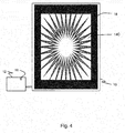
- the image 14 may instead be cropped around one or more edges to result in a smaller image 14c.
- the image is cropped evenly on all sides, though in other examples the image may be cropped on only one, two or three sides.
- the cropped image 14c again results in fewer light sources being active to generate or illuminate the image 14c. This is indicated schematically in Figure 4 again by the black border 18 which indicates where light sources are not active.
- Whether or not to shrink the image (as described with reference to Figures 1 to 3 ) or to crop the image (as described with reference to Figure 4 ) may be an option that is available to the processor and which may depend on for example the nature of the image that is being displayed. For example, depending on the particular image, it may be that peripheral regions of the image are substantially uniform and therefore can be removed by cropping the image without any (significant) loss of information or without (significantly) affecting the aesthetics of the display for viewers. If on the other hand the image is such that all components of the image are important (as in the case of for example an image that is displaying text-based information), then it may be better to shrink the image than to crop the image.
- Image analysis techniques may be applied by the processor of the processing unit 12 to determine whether it might be better to shrink the image or crop the image for the particular image that is being displayed at any particular time instant. A similar analysis may apply when deciding whether or not to preserve the aspect ratio of the original image following shrinking or cropping of the image.
- another option is to switch off selected ones of the light sources where the light sources that are switched off are spread across the display panel of the display device 10.
- This is illustrated schematically in Figure 5 by black dots 20 that indicate the location of light sources that have been switched off in this example.
- the light sources 20 that are switched off in this example may be arranged in for example a substantially regular array across the display device 10. To illustrate this, if for example it is desired to reduce the total number of active light sources by 1/6, then every 6th light source in a row across the display device 10 may be switched off. Successive rows of light sources in the display device may start at a different light source in the sense that in for example the first row, the first, seventh, etc.
- every 25th light source in a first row across the display device 10 may be switched off, with this being repeated for every 25th row of light sources of the display device 10 (with no light sources being switched off in intermediate rows).
- a number of different ways of arranging the thresholds for temperature to result in a reduction of the number of active light sources are possible. For example, if the temperature exceeds a first, high threshold, then the processor 12 may operate to reduce the number of active light sources by a large number or proportion. On the other hand, if the temperature only exceeds a second, relatively lower threshold temperature, then the processor 12 may operate to reduce the number of active light sources by a smaller amount or proportion.
- the threshold temperature that is used before the processor 12 operates to reduce the number of active light sources may depend on the drive current which is driving the light sources at that particular time (or for example the total current that is being consumed by the display device 10 at that particular time). For example, if the drive current is higher than a lower temperature threshold may be used to result in the number of active light sources being reduced and vice versa.
- Table 1 shows an example of different threshold temperatures that are used for different drive currents that are being used at any particular time to drive the light sources. (The amounts for the temperatures and drive currents that are shown are illustrative only.) Table 1 Temperature 30°C 35°C 40°C 45°C Total Drive Current 2.5 A 2 A 1.5 A 1A
- the advantage of this arrangement is that a higher drive current is more likely to lead to rapid excessive heating not only of the light sources but also of other components of the display device, including certain components of the mainboard of the display device, such as (power) transistors that switch or control the drive current provided to the light sources. Accordingly, the use of a lower temperature threshold when the drive current is higher results in safer operation and a display device 10 that is less likely to malfunction. Conversely, if a lower drive current is being used, a higher ambient temperature can be tolerated before action needs to be taken to reduce the number of active light sources.
- the temperature continues to be monitored by the processor 12. As mentioned for the first example above, if the temperature continues to be above a threshold, then the number of active light sources can be reduced further. On the other hand, if the temperature falls below the threshold, then the number of light sources that are generating or illuminating the image may be increased again. That increase may be smaller than the decrease in number of light sources that resulted in that temperature drop in the first place. This may continue until the temperature possibly rises above the threshold again, in which case the number of active light sources will be reduced again. In this way, the image may then again be restored at least close towards its original size or resolution.
- the number of active light sources is reduced when the temperature is above a threshold, or the number of active light sources is possibly increased again after a sufficient temperature drop, such changes may be made relatively slowly and potentially gradually so as to avoid the changes being noticed by viewers (or at least causal viewers). That is, by way of example, if it is desired to reduce the number of active light sources by say 15%, it may be that in a first period of time (of say a handful of seconds, such as three seconds), the number of active light sources is reduced by 3%; then in the next period of time, the number of light sources is reduced by the same 3% (i.e. three percentage points), etc., until the desired total reduction of the number of light sources that are active has been achieved (in this case, by five small steps of 3% each).
- this method can effectively be carried out in reverse. For example, if the temperature is recorded to be relatively low, then this indicates that a higher drive current can be tolerated. This means that with lower temperatures, a larger number of light sources may be used to generate or illuminate the image without causing problems from excessive heat. This might be of particular interest at night time when ambient temperatures tend to be lower, meaning that a larger number of light sources can be used for the image. Alternatively, or additionally, using these thresholds, the brightness of the light sources may be increased to a maximum value and yet still the temperature as measured by the temperature sensor 16 is below the threshold. Either way, this can help to make the image more noticeable to users at night, when temperatures are generally lowest. This may be particularly important in the case that the display device is for controlling road traffic, where illuminated road signs are important for night.
- temperature thresholds for the different parts or components of the display device, the temperature of each of which is monitored, and any of which may result in reducing the number of light sources that are generating or illuminating an image if the temperature exceeds the threshold.
- a temperature threshold of say 85°C for the main integrated circuit that handles the video processing a temperature threshold of say 60°C for the display screen itself of the display device 10 or the strings of light sources (such as LEDs), etc.
- processor or processing system or circuitry referred to herein may in practice be provided by a single chip or integrated circuit or plural chips or integrated circuits, optionally provided as a chipset, an application-specific integrated circuit (ASIC), field-programmable gate array (FPGA), digital signal processor (DSP), graphics processing units (GPUs), etc.
- the chip or chips may comprise circuitry (as well as possibly firmware) for embodying at least one or more of a data processor or processors and a digital signal processor or processors, which are configurable so as to operate in accordance with the exemplary embodiments.
- the exemplary embodiments may be implemented at least in part by computer software stored in (non-transitory) memory and executable by the processor, or by hardware, or by a combination of tangibly stored software and hardware (and tangibly stored firmware).
- the invention also extends to computer programs, particularly computer programs on or in a carrier, adapted for putting the invention into practice.
- the program may be in the form of non-transitory source code, object code, a code intermediate source and object code such as in partially compiled form, or in any other non-transitory form suitable for use in the implementation of processes according to the invention.
- the carrier may be any entity or device capable of carrying the program.
- the carrier may comprise a storage medium, such as a solid-state drive (SSD) or other semiconductor-based RAM; a ROM, for example a CD ROM or a semiconductor ROM; a magnetic recording medium, for example a floppy disk or hard disk; optical memory devices in general; etc.
- SSD solid-state drive
- ROM read-only memory
- magnetic recording medium for example a floppy disk or hard disk
- optical memory devices in general etc.
Priority Applications (2)
| Application Number | Priority Date | Filing Date | Title |
|---|---|---|---|
| EP17187592.5A EP3447757A1 (fr) | 2017-08-23 | 2017-08-23 | Dispositif d'affichage et son procédé de fabrication |
| TR2017/12932A TR201712932A2 (tr) | 2017-08-23 | 2017-08-29 | Görüntüleme aygiti ve çalişma yöntemi̇ |
Applications Claiming Priority (1)
| Application Number | Priority Date | Filing Date | Title |
|---|---|---|---|
| EP17187592.5A EP3447757A1 (fr) | 2017-08-23 | 2017-08-23 | Dispositif d'affichage et son procédé de fabrication |
Publications (1)
| Publication Number | Publication Date |
|---|---|
| EP3447757A1 true EP3447757A1 (fr) | 2019-02-27 |
Family
ID=59699547
Family Applications (1)
| Application Number | Title | Priority Date | Filing Date |
|---|---|---|---|
| EP17187592.5A Withdrawn EP3447757A1 (fr) | 2017-08-23 | 2017-08-23 | Dispositif d'affichage et son procédé de fabrication |
Country Status (2)
| Country | Link |
|---|---|
| EP (1) | EP3447757A1 (fr) |
| TR (1) | TR201712932A2 (fr) |
Citations (5)
| Publication number | Priority date | Publication date | Assignee | Title |
|---|---|---|---|---|
| US20050151717A1 (en) * | 2003-12-18 | 2005-07-14 | Samsung Electronics Co., Ltd. | Backlight control circuit in portable device |
| US20110292090A1 (en) * | 2010-05-25 | 2011-12-01 | Sanyo Electric Co., Ltd. | Display apparatus |
| EP2555183A2 (fr) * | 2011-08-04 | 2013-02-06 | Samsung Electronics Co., Ltd. | Unité de rétroéclairage et procédé de commande de DEL |
| US20150377949A1 (en) * | 2014-06-30 | 2015-12-31 | Landis+Gyr, Inc. | Utility Meter with Temperature Sensor |
| WO2016027705A1 (fr) * | 2014-08-20 | 2016-02-25 | 日本精機株式会社 | Dispositif d'affichage à cristaux liquides et dispositif d'affichage tête haute |
-
2017
- 2017-08-23 EP EP17187592.5A patent/EP3447757A1/fr not_active Withdrawn
- 2017-08-29 TR TR2017/12932A patent/TR201712932A2/tr unknown
Patent Citations (5)
| Publication number | Priority date | Publication date | Assignee | Title |
|---|---|---|---|---|
| US20050151717A1 (en) * | 2003-12-18 | 2005-07-14 | Samsung Electronics Co., Ltd. | Backlight control circuit in portable device |
| US20110292090A1 (en) * | 2010-05-25 | 2011-12-01 | Sanyo Electric Co., Ltd. | Display apparatus |
| EP2555183A2 (fr) * | 2011-08-04 | 2013-02-06 | Samsung Electronics Co., Ltd. | Unité de rétroéclairage et procédé de commande de DEL |
| US20150377949A1 (en) * | 2014-06-30 | 2015-12-31 | Landis+Gyr, Inc. | Utility Meter with Temperature Sensor |
| WO2016027705A1 (fr) * | 2014-08-20 | 2016-02-25 | 日本精機株式会社 | Dispositif d'affichage à cristaux liquides et dispositif d'affichage tête haute |
Also Published As
| Publication number | Publication date |
|---|---|
| TR201712932A2 (tr) | 2019-03-21 |
Similar Documents
| Publication | Publication Date | Title |
|---|---|---|
| US8730219B2 (en) | Display device | |
| KR102644977B1 (ko) | 디스플레이 시스템, 그에 대한 전력 제어 방법 및 비정적 순전력 제어 이득 레벨을 생성하는 방법 | |
| WO2010016440A1 (fr) | Rétroéclairage et dispositif d'affichage l'utilisant | |
| US20100231573A1 (en) | Backlight device and liquid crystal displaying device using the backlight device | |
| CN111696477B (zh) | 一种超高清电视的显示控制方法及8k超高清电视 | |
| JP2010267481A (ja) | バックライト装置および表示装置 | |
| US20120212466A1 (en) | Display device | |
| US11735100B2 (en) | Display panel and driving method thereof | |
| JP2012003156A (ja) | 表示装置 | |
| KR20100095282A (ko) | 광원 구동 방법 | |
| JP4293747B2 (ja) | 有機el表示装置およびその制御方法 | |
| JP2004205704A (ja) | 有機elディスプレイ | |
| US20130093797A1 (en) | Backlight control unit and display device using same and backlight control method | |
| US20060209006A1 (en) | LCD display module | |
| US9966012B2 (en) | Image display apparatus and control method thereof | |
| US20210142743A1 (en) | Control device and liquid crystal display device provided with control device | |
| JP2003108073A (ja) | 自己発光型表示装置 | |
| KR102600444B1 (ko) | 발광표시장치 | |
| EP3447757A1 (fr) | Dispositif d'affichage et son procédé de fabrication | |
| US10825381B2 (en) | Display system and method for controlling display system | |
| CN111292688B (zh) | 屏幕亮度调节方法及装置、显示装置 | |
| CN110767183B (zh) | 显示装置与其背光驱动方法 | |
| US20180061331A1 (en) | Display apparatus, method, and medium for displaying an image | |
| JP2000066652A (ja) | 画像再生機器でのルミナンス制御装置 | |
| KR20140068699A (ko) | 전력 소비를 감소시키는 디스플레이 장치 및 방법 |
Legal Events
| Date | Code | Title | Description |
|---|---|---|---|
| PUAI | Public reference made under article 153(3) epc to a published international application that has entered the european phase |
Free format text: ORIGINAL CODE: 0009012 |
|
| STAA | Information on the status of an ep patent application or granted ep patent |
Free format text: STATUS: THE APPLICATION HAS BEEN PUBLISHED |
|
| AK | Designated contracting states |
Kind code of ref document: A1 Designated state(s): AL AT BE BG CH CY CZ DE DK EE ES FI FR GB GR HR HU IE IS IT LI LT LU LV MC MK MT NL NO PL PT RO RS SE SI SK SM TR |
|
| AX | Request for extension of the european patent |
Extension state: BA ME |
|
| STAA | Information on the status of an ep patent application or granted ep patent |
Free format text: STATUS: REQUEST FOR EXAMINATION WAS MADE |
|
| 17P | Request for examination filed |
Effective date: 20190827 |
|
| RBV | Designated contracting states (corrected) |
Designated state(s): AL AT BE BG CH CY CZ DE DK EE ES FI FR GB GR HR HU IE IS IT LI LT LU LV MC MK MT NL NO PL PT RO RS SE SI SK SM TR |
|
| STAA | Information on the status of an ep patent application or granted ep patent |
Free format text: STATUS: EXAMINATION IS IN PROGRESS |
|
| 17Q | First examination report despatched |
Effective date: 20201015 |
|
| STAA | Information on the status of an ep patent application or granted ep patent |
Free format text: STATUS: EXAMINATION IS IN PROGRESS |
|
| STAA | Information on the status of an ep patent application or granted ep patent |
Free format text: STATUS: THE APPLICATION IS DEEMED TO BE WITHDRAWN |
|
| 18D | Application deemed to be withdrawn |
Effective date: 20220301 |