EP2554484B1 - Labeler - Google Patents
Labeler Download PDFInfo
- Publication number
- EP2554484B1 EP2554484B1 EP10849036.8A EP10849036A EP2554484B1 EP 2554484 B1 EP2554484 B1 EP 2554484B1 EP 10849036 A EP10849036 A EP 10849036A EP 2554484 B1 EP2554484 B1 EP 2554484B1
- Authority
- EP
- European Patent Office
- Prior art keywords
- labeler
- label
- container
- condition
- picker
- Prior art date
- Legal status (The legal status is an assumption and is not a legal conclusion. Google has not performed a legal analysis and makes no representation as to the accuracy of the status listed.)
- Active
Links
Images


Classifications
-
- B—PERFORMING OPERATIONS; TRANSPORTING
- B65—CONVEYING; PACKING; STORING; HANDLING THIN OR FILAMENTARY MATERIAL
- B65C—LABELLING OR TAGGING MACHINES, APPARATUS, OR PROCESSES
- B65C3/00—Labelling other than flat surfaces
- B65C3/06—Affixing labels to short rigid containers
- B65C3/065—Affixing labels to short rigid containers by placing tubular labels around the container
-
- B—PERFORMING OPERATIONS; TRANSPORTING
- B65—CONVEYING; PACKING; STORING; HANDLING THIN OR FILAMENTARY MATERIAL
- B65C—LABELLING OR TAGGING MACHINES, APPARATUS, OR PROCESSES
- B65C3/00—Labelling other than flat surfaces
- B65C3/06—Affixing labels to short rigid containers
- B65C3/08—Affixing labels to short rigid containers to container bodies
- B65C3/14—Affixing labels to short rigid containers to container bodies the container being positioned for labelling with its centre-line vertical
- B65C3/16—Affixing labels to short rigid containers to container bodies the container being positioned for labelling with its centre-line vertical by rolling the labels onto cylindrical containers, e.g. bottles
- B65C3/163—Affixing labels to short rigid containers to container bodies the container being positioned for labelling with its centre-line vertical by rolling the labels onto cylindrical containers, e.g. bottles where the label is of the wrap-around type
-
- B—PERFORMING OPERATIONS; TRANSPORTING
- B65—CONVEYING; PACKING; STORING; HANDLING THIN OR FILAMENTARY MATERIAL
- B65B—MACHINES, APPARATUS OR DEVICES FOR, OR METHODS OF, PACKAGING ARTICLES OR MATERIALS; UNPACKING
- B65B53/00—Shrinking wrappers, containers, or container covers during or after packaging
- B65B53/02—Shrinking wrappers, containers, or container covers during or after packaging by heat
- B65B53/06—Shrinking wrappers, containers, or container covers during or after packaging by heat supplied by gases, e.g. hot-air jets
- B65B53/063—Tunnels
Definitions
- the present invention relates to a labeler and, in particular, to a labeler which can switch between a first labeler condition in which a label is affixed to a side surface of a container and a second labeler condition in which a cylindrical shrink label is attached to a container.
- the said labeler which affixes a label to a side surface of a container is provided with label supply means to match the height of a container placed on a rotary table, and this label supply means is adapted to affix a label directly to the container (Patent Literature 1).
- shrink label supply means is provided to match the height of a mandrel which is provided on a rotary table in such a manner as to be rotatable, a shrink label is wound on the mandrel and formed in the shape of a cylinder, and thereafter this shrink label is attached in such a manner as to cover the container from above (Patent Literature 2).
- WO 2007/031502 A2 discloses a labeller for forming a shrink sleeve label around a mandrel and subsequently applying said label onto a container.
- the present invention provides a labeler which can serve as both a labeler which affixes a label directly to a side surface of a container and a shrink labeler which uses a mandrel.
- the labeler of the present invention is a labeler which can switch between a first labeler condition in which a label is affixed to a container and a second labeler condition in which a cylindrical shrink label is attached to the container.
- the labeler is provided with a support table which is rotatably provided on a rotary table and places a container thereon; a mandrel which is rotatably provided above the support table and forms the shrink label on an outer surface thereof; label supply means which supplies a label before affixing or a shrink label before forming; a picker which sticks fast and holds a shrink label on an inner surface thereof; and switching means which switches the position of the picker to match the said first labeler condition or the said second labeler condition.
- the said label supply means affixes a label to a container placed on the said support table.
- the said label supply means supplies a shrink label to an outer surface of the mandrel to form a shrink label
- the said picker receives, with an inner surface thereof, the shrink label on the outer surface of the mandrel and attaches the shrink label to the container.
- the said label supply means is adapted to affix a label directly to a container at the height of the container, and at this time the said picker has retracted from the container so as not to interfere with the said label supply means.
- the said label supply means supplies a shrink label to the said mandrel at the height of the mandrel, and at this time the picker has retracted from the mandrel.
- the picker When thereafter a shrink label is formed on the mandrel, the picker ascends to the mandrel, and when the shrink label is delivered from the mandrel to the picker, the picker descends again to the container placed on the said support table and the shrink label is attached to the container.
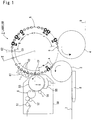
- Figure 1 shows a plan view of a labeler 2 which affixes a label to a container 1, such as a PET bottle.
- the labeler is provided between a container supply star wheel 3 which supplies containers 1 and a container discharge star wheel 4 which discharges labeled containers 1 to a succeeding process.
- the said labeler 2 is composed of a rotary table 5 which receives a container 1 from the container supply star wheel 3 and delivers a labeled container 1 to the container discharge star wheel 4 and label supply means 6 which supplies labels.
- the labeler 2 of this embodiment can switch between a roll labeler condition as a first labeler condition in which the labeler can be used as what is called a roll labeler which affixes a label directly to a side surface of the container 1 and a shrink labeler condition as a second labeler condition in which the labeler can be used as what is called a shrink labeler which attaches shrink label formed in the shape of a cylinder to the container 1.
- a roll labeler condition as a first labeler condition in which the labeler can be used as what is called a roll labeler which affixes a label directly to a side surface of the container 1
- a shrink labeler condition as a second labeler condition in which the labeler can be used as what is called a shrink labeler which attaches shrink label formed in the shape of a cylinder to the container 1.
- a supply conveyor 7 which conveys containers 1 in a line and a screw 8 which is provided on the downstream side of this supply conveyor 7 and supplies containers 1 spaced at prescribed intervals to the container supply star wheel 3.
- a discharge conveyor 9 which receives containers 1 from the container discharge star wheel 4 and conveys the containers 1 in a line.
- the said container supply star wheel 3 and container discharge star wheel 4 are each provided with a plurality of pockets which house and hold containers 1 at the outer circumferences thereof, though not shown, and perform the supply of containers 1 and the discharge of containers 1 in the receiving position A and delivery position G, respectively, of Figure 1 by holding the containers 1.
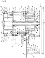
- the said rotary table 5 is provided with a center shaft 12 fixed to a base 11, first to third plates 13 to 15 which rotate around this center shaft 12 and are provided in this order from below, a support table 16 which is provided on the first plate 13 and places the said container 1 thereon, a mandrel 17 which is provided above this support table 16 and forms the said shrink label into the shape of a cylinder, a servo motor 18 which is provided on the second plate 14 and rotates the support table 16 and the mandrel 17, a top locator 19 which is provided in such a manner as to ascend and descend and be rotatable above the support table 16 and fits onto a mouth portion of the said container 1, and a picker 20 which attaches a shrink label formed on the said mandrel 17 to the container 1.
- the said first to third plates 13 to 15 are connected in such a manner as to rotate in an integral manner around the said center shaft 12, and on the outer circumferences of these first to third plates 13 to 15 there are provided the said support table 16, mandrel 17, top locator 19, and picker 20 each at equal intervals.
- first to third plates 13 to 15 rotate by the driving force of a motor, which is not shown, and are adapted to rotate in synchronization with the said container supply star wheel 3 and container discharge star wheel 4 by transmission means, which is not shown.
- the said support table 16 is provided in such a manner as to pierce the first plate 13 vertically and be rotatable with respect to the first plate 13, with an upper surface thereof worked to be flat to place the said container 1 thereon and a first gear 16a provided in a lower end portion thereof.
- the said servo motor 18 which rotates this support table 16 is provided on an upper surface of the second plate 14 as shown in Figure 2 , a driving shaft 18a thereof pierces the second plate 14 and protrudes downward, piercing the said first plate 13 to below, and a second gear 18b is provided at a lower end of the first plate.
- a cylindrical sleeve 21 which pierces the first plate 13 vertically is provided between the said support table 16 and the driving shaft 18a in the said first plate 13, and a third gear 22 which meshes with the said first gear 16a and second gear 18b is rotatably mounted on the outer circumference of this sleeve 21.
- the said mandrel 17 is a hollow cylindrical member, and is detachably provided on an outer circumferential surface of a cylindrical member 23, which is provided in such a manner as to pierce the second plate 14 vertically and be rotatable with respect to the second plate 14, the center thereof coincides with the center shaft of the said support table 16.
- a vacuum passage 24 in the form of a hollow tube which is connected to an upper part of the said top locator 19 is provided in such a manner as to be movable vertically, and this vacuum passage 24 is connected to suction means, which is not shown.
- the length of the said mandrel 17 is fabricated to match the vertical length of a shrink label to be treated and the outside diameter thereof is fabricated to be equal to the outside diameter of the said container 1 or larger than this outside diameter to permit replacement to match a shrink label attached to the container 1.
- a plurality of attraction holes 17a are formed, providing communication with a space S formed between the inner surface of the mandrel 17 formed below the cylindrical member 23 and the outer surface of the vacuum passage 24.
- the vacuum passage 24 includes a communication bore 24a formed therein in communication with the attraction holes 17a through the space S.
- the suction means is actuated to attract and hold a shrink label by vacuum at the attraction holes 17a on the outer surface of the mandrel 17.
- a fourth gear 23a is provided in an upper end portion of the said cylindrical member 23 and a fifth gear 18c is provided in a driving shaft 18a of the said servo motor 18. And between the fourth and fifth gears 23a, 18c, a sixth gear 25 is rotatably provided in the second plate 14.
- the sectional shape of the outer surface of the said mandrel 17 is not limited to a circle and may be a polygon, such as a quadrangle and a hexagon.
- the top locator 19 is rotatably provided at a lower end of the said vacuum passage 24 which pierces the said cylindrical member 23, and a lower end portion of this top locator 19 is formed in such a manner as to fit onto the mouth portion of the said container 1.
- a sliding member 27 which ascends and descends along a slide rail 26 provided at the third plate 15, and a first cam follower 27a is provided in this sliding member 27.
- a first cam 28 is provided in such a manner as to surround the rotary table 5 and is adapted to move the sliding member 27 vertically by the engagement of the said first cam follower 27a.
- the picker 20 is composed of two members having a semicircular section, which are formed to match the diameter of the container 1, and the two pickers 20 are opened and closed by an opening and closing mechanism 29 shown in Figure 3 and is adapted to be lifted and lowered between the first plate 13 and the second plate 14 by a lifting and lowering mechanism 30 shown in Figure 2 .
- Figure 5 shows a diagram in which the picker 20 is in an open condition brought about by the opening and closing mechanism 29.
- the diameter of the inner surface formed by causing the said two pickers 20 to abut against each other, is somewhat larger than the outside diameter of the said mandrel 17, that is, a little larger than the outside diameter of the container 1.
- a plurality of attraction holes 20a are formed in the inner surface of each of the pickers 20, and these attraction holes 20a are in communication with suction means via an unillustrated tube connected to the outer side of the picker 20.
- the attraction holes 20a in the inner surface of the picker 20 are adapted to attract and hold a shrink label by vacuum.
- the sectional shape of the inner surface obtained when the picker 20 is brought into a closed condition is not limited to a circle and may be a polygon, such as a quadrangle and a hexagon, and a gap may be formed in part of the inner surface in a closed condition.
- the said opening and closing mechanism 29 is composed of a holding plate 31 which is lifted and lowered by the said lifting and lowering mechanism 30, two stays 32 which hold the said two pickers 20 on this holding plate 31 in such a manner as to permit opening and closing, an opening and closing rod 33 which is provided at the base of either of the stays 32 and pierces the sleeve 21 provided on the said first plate 13, a lever 34 which rotates this opening and closing rod 33, a second cam follower 35 provided at the forward end of this lever 34, and a second cam 36 which is fixed to the said base 11 and with which the said second cam follower 35 engages.
- a gear 32a is formed in each of the bases of the said two stays 32, and when either of the stays 32 is rotated by the said opening and closing rod 33, the other stay 32 rotates in response to this rotation, as a result of which the picker 20 is adapted to open and close.
- the said opening and closing rod 33 is provided on a further inner side of the holder 37, which is rotatably provided on a further inner side of the sleeve 21 which is fixed to the said first plate 13.
- the opening and closing rod 33 and the holder 37 are splined to each other, and are prevented from rotating although the two perform vertical relative movement mutually.
- the said lever 34 is fixed to a lower end of the said holder 37.
- the said rod lifting and lowering mechanism 30 is composed of a lifting and lowering rod 38 which is provided below the said holding plate 31 and pierces the first plate 13 downward, a sliding member 39 provided at a lower end of the lifting and lowering rod 38, a slide rail 40 which is fixed below the first plate 13 and guides the said sliding member 39, and a third cam 42 which engages with a third cam follower 41 provided in the said sliding member 39.
- the said sliding member 39 is adapted to ascend and descend up and down along the said slide rail 40, and the said picker 20 surrounds the said container 1 when the sliding member 39 is positioned below, whereas the said picker 20 surrounds the mandrel 17 when the sliding member 39 is positioned above.
- the said third cam 42 has two different paths for each of the roll labeler condition and the shrink labeler condition of the labeler 2, and switching means 43 is provided in the position where the two paths branch.
- Figure 6 shows a schematic diagram of the said third cam 42 and switching means 43, and the third cam 42 has one path in the zone of the third cam 42 in which the height of the picker 20 is the same in the roll labeler condition and in the shrink labeler condition.
- the third cam 42 branches into two paths, an upper path 42a and a lower path 42b, and the said switching means 43 are provided in a position where the two paths branch and in a position where the two paths merge.
- the switching means 43 is composed of a cam plate 44 where the two paths branch or merge and an air cylinder 45 which lifts and lowers this cam plate 44.
- the cam plate 44 is lifted and lowered by this air cylinder 45, whereby the said third cam follower 41 is adapted to be guided into the path for the roll labeler condition in the third cam 42 or the path for the shrink labeler condition.
- the switching means 43 shown in Figure 6 shows the shrink labeler condition in which the cam plate 44 is lowered and the third cam follower 41 is guided into the lower path 42b, and in the roll labeler condition the cam plate 44 is lifted and the third cam follower 41 is guided into the upper path 42a.
- the switching means 43 is not limited to the said cam and may have a configuration in which, for example, driving means, such as a servo motor, is arranged for each of the pickers 20 and each picker 20 is controlled independently.
- driving means such as a servo motor
- the said label supply means 6 is provided with a feed roller 51 which supplies a label by drawing out the label which is wound in roll form, a rotary cutter 52 which cuts a label to a prescribed length, and an affixing drum 53 which affixes a label to the said container 1 or the said mandrel 17 in the affixing position C1 in Figure 1 , and these are adapted to be rotated by a motor 54 shown in Figure 2 in synchronization with each other.
- the label supply means 6 is provided with heating means 55 which is used in the said roll labeler condition and a UV-curable paste application roller 56 which is used in the shrink labeler condition.
- Both the heating means 55 and the UV-curable paste application roller 56 are arranged in such a manner as to be movable to a forward movement position and a backward movement position, and are adapted to be positioned in the forward movement position while operative and in the backward movement position while inoperative.
- the label supply means 6 having this configuration is adapted to be lifted and lowered by lifting and lowering means 57 shown in Figure 2 and this lifting and lowering means 57 is provided with a lifting and lowering base 58 where the said affixing drum 53 and the like are installed and a motor 59 provided on the said base 11.
- a bracket 58a provided below the said lifting and lowering base 58 is attached to a nut 60a screwed onto a ball screw 60 rotated by the motor 59 and the motor 59 is rotated, whereby the bracket 58a is moved up and down and the label supply means 6 is lifted and lowered.
- a plurality of wiping rollers 61 which press overlapping portions of a shrink label to the wiping position C2 downstream of the said affixing position C1 in the rotation direction are provided, and UV irradiation means 62 which irradiates overlapping portions of the shrink label with ultraviolet rays is provided in the curing position C3 further downstream in the rotation direction.
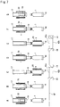
- Figure 7 shows an operational explanatory diagram of the actions of the support table 16, mandrel 17, pickers 20, and top locator 19 expected when the labeler 2 is brought into action in the shrink labeler condition, and cam paths by the said third cam 42 and the cam plate 44 in the switching means 43 are shown in the lower part of the figure.
- the said cam plate 44 is lowered, whereby the third cam follower 41 is caused to pass through the lower cam path 42b in the third cam 42.
- the said label supply means 6 is brought into a lifted condition by the said lifting and lowering means 57, as a result of which the said affixing drum 53 is positioned at the height of the said mandrel 17. Furthermore, the said UV-curable paste application roller 56 has moved forward and is in an operative position and the said heating means 65 has moved backward and is in an inoperative condition.
- a to G in each diagram of Figure 7 corresponds to the position or zone shown in A to G in Figure 1 , respectively.
- the said top locator 19 has retracted to above the container 1 by use of the first cam 28 and also the said picker 20 has retracted to the same height as the mandrel 17 by use of the third cam 42.
- the top locator 19 is lowered by the first cam 28 and fits into the mouth portion of the container 1, and the container 1 is sandwiched by the support table 16 and the top locator 19.
- the rotary table 5 rotates further and in the start position of the zone C, i.e., in a position on the upstream side of the rotation direction from the affixing position C1 by the said label supply means 6, the picker 20 is lowered to the height of the container 1 by the third cam 42 whose path is set by the said switching means 43 to the lower path 42b.
- the second cam 36 of the opening and closing mechanism 29 which opens and closes the said picker 20 is arranged in such a manner as to bring the said picker 20 into an open condition, as a result of which a gap is formed between the container 1 and the picker 20.
- a shrink label supplied by the said feed roller 51 is cut by the said rotary cutter 52 into such a length that the shrink label surrounds the outer circumference of the container 1 and the forward end portion and backward end portion thereof overlap, and furthermore, a UV-curable paste is applied by the said UV-curable paste application roller 56 in an up-and-down direction to a backward end portion of a rear surface of the shrink label sticking to the surface of the affixing drum 53.
- the attraction holes 17a of the mandrel 17 suck the said shrink label by being brought into communication with the suction means via the said vacuum passage 24, and the affixing drum 53 cancels the suction of the shrink label, with the result that the shrink label is delivered from the affixing drum 53 to the mandrel 17.
- the shrink label goes round the mandrel 17 once, the forward end portion and backward end portion thereof are adapted to overlap one another, and on that occasion the UV-curable paste applied to the backward end portion is adapted to adhere to the forward end portion.
- the said wiping roller 61 approaches the mandrel 17 and presses the overlapping portions of the shrink label from outside and the overlapping portions of the shrink label are adapted to adhere tightly to each other.
- the said mandrel 17 does not rotate until the rotary table 5 rotates further and the container 1 moves to the curing position C3, as a result of which the overlapping portions of the said shrink label are adapted to face the UV irradiation means 62.
- the said UV irradiation means 62 irradiates the overlapping portions of the shrink label with ultraviolet rays, the UV-curable paste is cured by this and the forward end portion and backward end portion of the shrink label are bonded together, with the result that the shrink label is formed on the outer surface of the mandrel 17.
- the said picker 20 is lifted by the said third cam 42 to the position of the mandrel 17 and the picker 20, which has been in an open condition, brought into a closed condition by the said second cam 36 in this zone D.
- the said suction means communicates with the attraction holes 20a of the picker 20, suctioning the said shrink label, and the shrink label which has been attracted and held by vacuum on the attraction holes 17a of the mandrel 17 is attracted and held by vacuum on the attraction holes 20a of the picker 20 by the interruption of the communication between the attraction holes 17a of the said mandrel 17 and the attraction means.
- the said servo motor 18 rotates the support table 16 at a prescribed speed, and in this condition the said picker 20 is lowered by the third cam 42 and the shrink label is attached to the container 1.
- the container 1 is rotated by the support table 16, the container 1 is inserted into the shrink label attracted and held by vacuum on the said picker 20 while rotating, as a result of which the curling of the shrink label by the container 1 is prevented.
- the shrink label may be attached, with the container 1 kept in a still condition without rotation.
- the container 1 to which the said shrink label is attached is then supplied to a shrink tunnel, which is not shown, and is adapted to adhere tightly to the container 1 by being shrank by heat.
- Figure 8 shows an operational explanatory diagram of the actions of the support table 16, mandrel 17, picker 20, and top locator 19 expected when the labeler 2 is brought into action in the roll labeler condition, and cam paths by the said third cam 42 and the cam plate 44 in the switching means 43 are shown in the lower part of the figure.
- the said cam plate 44 is lifted, whereby the third cam follower 41 is caused to pass through the upper path 42a of the third cam 42.
- the said label supply means 6 is lowered by the said lifting and lowering means 57 and the said affixing drum 53 is positioned at the height of the container 1 placed on the support table 16.
- the said heating means 55 is positioned in an operative position by moving forward the said heating means 55, and the said UV-curable paste application roller 56 and the said wiping roller 61 are brought into inoperative positions by moving backward and also the UV irradiation means 62 is brought into an inoperative condition.
- the container 1 held by the pocket of the container supply star wheel 3 is placed on the support table 16 of the rotary table 5, whereas in the position B the top locator 19 is lowered by the first cam 28, and the container 1 is adapted to be sandwiched by the support table 16 and the top locator 19.
- the heating means 55 adjacent to the said affixing drum 53 generates adhesive force on the rear surface of the label by heating the thermally-active paste applied beforehand to the rear surface of the label.
- the label to be affixed at this time may be a label which is wound on the whole circumference of the container 1 or may be a label which is affixed to part of the outer peripheral surface of the container 1.
- the servo motor 18 stops the rotation of the support table 16, and when the container has reached the delivery position G, the top locator 19 is lifted by the said first cam 28 and leaves the container 1, and the container 1 is held by the pocket of the said container discharge star wheel 4 and is discharged onto the said discharge conveyor 9.
- this labeler can serve as both a roll labeler which affixes a label directly to the container 1 and a shrink labeler which attaches a shrink label formed in the shape of cylinder from the mandrel 17 to the container 1, enabling the installation place and cost to be substantially reduced compared to the case where two labelers of a roll labeler and a shrink labeler are installed.
- the label supply means 6 is capable of lifting and lowering and can affix or deliver a label to both the container 1 and the mandrel 17, this labeler can serve as both a roll label and a shrink label by use of one label supply means.
- the said lifting and lowering means 57 becomes unnecessary if for the said label supply means 6, two different label supply means 6 for roll labels and for shrink labels are provided and are installed at different heights.
- the said label supply means 6 for roll labels is label supply means which supplies what is called sheet-fed labels which are such that labels are cut beforehand into a prescribed shape and length
- the labeler of this embodiment is also possible to use the labeler of this embodiment as a sheet-feed labeler and a shrink labeler.
- the said support table 16 and mandrel 17 are driven by one servo motor 18, it is possible to adopt a configuration in which the support table 16 and the mandrel 17 are provided on the first plate 13 and the second plate 14, respectively, and are individually driven.
- bonding is performed by applying a UV-curable paste and by irradiating the overlapping portions of the label with UV rays
- bonding may be performed using, for example, a hot melt and a laser.
- the shrink label is attached to the container 1 and is caused to shrink in a succeeding process, which is not shown, it is also possible to provide a heater in the said picker 20 and to shrink the shrink label by heat in the zone E of Figure 1 , for example.
Landscapes
- Labeling Devices (AREA)
Applications Claiming Priority (2)
| Application Number | Priority Date | Filing Date | Title |
|---|---|---|---|
| JP2010082729A JP5434750B2 (ja) | 2010-03-31 | 2010-03-31 | ラベラー |
| PCT/JP2010/073549 WO2011121866A1 (ja) | 2010-03-31 | 2010-12-27 | ラベラー |
Publications (3)
| Publication Number | Publication Date |
|---|---|
| EP2554484A1 EP2554484A1 (en) | 2013-02-06 |
| EP2554484A4 EP2554484A4 (en) | 2015-11-18 |
| EP2554484B1 true EP2554484B1 (en) | 2018-08-22 |
Family
ID=44711638
Family Applications (1)
| Application Number | Title | Priority Date | Filing Date |
|---|---|---|---|
| EP10849036.8A Active EP2554484B1 (en) | 2010-03-31 | 2010-12-27 | Labeler |
Country Status (3)
| Country | Link |
|---|---|
| EP (1) | EP2554484B1 (enExample) |
| JP (1) | JP5434750B2 (enExample) |
| WO (1) | WO2011121866A1 (enExample) |
Families Citing this family (5)
| Publication number | Priority date | Publication date | Assignee | Title |
|---|---|---|---|---|
| CN103442986B (zh) | 2011-02-11 | 2015-12-09 | 西得乐独资股份公司 | 用于输送管状标签的真空输送件和方法 |
| JP6003043B2 (ja) * | 2011-11-14 | 2016-10-05 | シブヤマシナリー株式会社 | 樹脂製ラベル装着装置および樹脂製ラベル装着方法 |
| JP6116316B2 (ja) * | 2013-03-28 | 2017-04-19 | 株式会社フジシールインターナショナル | フィルム被嵌装置 |
| JP6146609B2 (ja) * | 2013-04-15 | 2017-06-14 | シブヤマシナリー株式会社 | ラベラ |
| JP6146608B2 (ja) * | 2013-04-15 | 2017-06-14 | シブヤマシナリー株式会社 | ラベラ |
Family Cites Families (11)
| Publication number | Priority date | Publication date | Assignee | Title |
|---|---|---|---|---|
| JPS5833813B2 (ja) * | 1977-12-19 | 1983-07-22 | 東洋ガラス株式会社 | プラスチツクスリ−ブの製造方法および装置 |
| JPS61164933A (ja) * | 1984-12-20 | 1986-07-25 | クロネス・ア−ゲ−・ヘルマン・クロンセデル・マシ−ネンフアブリ−ク | 容器用ラベル貼付機械 |
| JPH039009A (ja) | 1989-06-02 | 1991-01-16 | Honda Motor Co Ltd | 内燃機関の動弁装置 |
| JPH0872839A (ja) * | 1994-09-07 | 1996-03-19 | K L Kk | ラベリングマシンのロールラベル自動補給装置 |
| JP2729474B2 (ja) * | 1995-07-10 | 1998-03-18 | 光洋自動機株式会社 | ラベリングマシン |
| JP3243718B2 (ja) * | 1999-06-21 | 2002-01-07 | 光洋自動機株式会社 | ラベル貼付方法及びラベル貼付装置 |
| JP2001240028A (ja) * | 2000-02-28 | 2001-09-04 | Koyo Autom Mach Co Ltd | ラベルの被着装置及び被着方法 |
| JP2002274518A (ja) * | 2001-03-15 | 2002-09-25 | Sansei Seiki Kk | シングルドラム型感熱ラベル、タックラベル兼用ラベラー |
| ITMO20050230A1 (it) * | 2005-09-12 | 2007-03-13 | Sacmi Labelling S P A | Apparato e metodo per ottenere etichette |
| JP4802865B2 (ja) * | 2006-05-29 | 2011-10-26 | 澁谷工業株式会社 | 筒状ラベル嵌装装置 |
| ITMO20060203A1 (it) | 2006-06-22 | 2007-12-23 | Sacmi Labelling S P A | Apparato e metodo per etichettare |
-
2010
- 2010-03-31 JP JP2010082729A patent/JP5434750B2/ja active Active
- 2010-12-27 EP EP10849036.8A patent/EP2554484B1/en active Active
- 2010-12-27 WO PCT/JP2010/073549 patent/WO2011121866A1/ja not_active Ceased
Also Published As
| Publication number | Publication date |
|---|---|
| JP5434750B2 (ja) | 2014-03-05 |
| EP2554484A1 (en) | 2013-02-06 |
| WO2011121866A1 (ja) | 2011-10-06 |
| JP2011213377A (ja) | 2011-10-27 |
| EP2554484A4 (en) | 2015-11-18 |
Similar Documents
| Publication | Publication Date | Title |
|---|---|---|
| EP2554484B1 (en) | Labeler | |
| JP6050256B2 (ja) | 筒形ラベル移送用の真空移送要素と方法複数の筒形ラベル移送用の真空移送要素と方法 | |
| US8899294B2 (en) | Labelling machine for sleeve labels | |
| US8871135B2 (en) | Labeler and a labeling method for labeling plastic bottles in a blow mold, in particular in a rotary blow molder | |
| CA2271141C (en) | Roll-fed labelling apparatus | |
| EP2387535B1 (de) | Behälterbehandlungsmaschine | |
| EP2550202B1 (en) | Labelling machine | |
| CN109476394B (zh) | 用led可固化的粘合剂固定环绕式标签 | |
| EP2716558B1 (en) | Film label-fitting device | |
| EP2883804B1 (en) | A labelling unit for applying a label onto an article | |
| CN113978872A (zh) | 一种瓶装饮用水生产用贴标机 | |
| US8790474B2 (en) | Reduction gripper for a cold glue unit | |
| EP2781460B1 (en) | Resin-label-mounting device and resin-label-mounting method | |
| EP2519445B1 (en) | Device for manufacturing a shrink sleeve label | |
| WO2011018807A1 (en) | A unit for applying a label on a relative article | |
| WO2012086066A1 (ja) | フィルム被嵌装置 | |
| CN221068808U (zh) | 一种瓶装杀虫剂用自动贴标装置 | |
| DE102015212134A1 (de) | Vorrichtung und Verfahren zum Etikettieren von Behältern | |
| EP2673199B1 (en) | A unit for applying a label on a relative article | |
| JP7132493B2 (ja) | ラベラ | |
| CA2682280A1 (en) | Labeling machine | |
| US20210380294A9 (en) | Method and Apparatus for Gripping and Holding Dispensing Elements, Having a Flange and a Screw Cap, for Subsequent Application onto Packages |
Legal Events
| Date | Code | Title | Description |
|---|---|---|---|
| PUAI | Public reference made under article 153(3) epc to a published international application that has entered the european phase |
Free format text: ORIGINAL CODE: 0009012 |
|
| 17P | Request for examination filed |
Effective date: 20121023 |
|
| AK | Designated contracting states |
Kind code of ref document: A1 Designated state(s): AL AT BE BG CH CY CZ DE DK EE ES FI FR GB GR HR HU IE IS IT LI LT LU LV MC MK MT NL NO PL PT RO RS SE SI SK SM TR |
|
| DAX | Request for extension of the european patent (deleted) | ||
| RA4 | Supplementary search report drawn up and despatched (corrected) |
Effective date: 20151020 |
|
| RIC1 | Information provided on ipc code assigned before grant |
Ipc: B65B 53/00 20060101ALI20151014BHEP Ipc: B65C 3/14 20060101AFI20151014BHEP Ipc: B65C 3/06 20060101ALI20151014BHEP Ipc: B65C 9/02 20060101ALI20151014BHEP Ipc: B65C 3/16 20060101ALI20151014BHEP Ipc: B65B 53/06 20060101ALI20151014BHEP |
|
| GRAP | Despatch of communication of intention to grant a patent |
Free format text: ORIGINAL CODE: EPIDOSNIGR1 |
|
| RIC1 | Information provided on ipc code assigned before grant |
Ipc: B65B 53/00 20060101ALI20180208BHEP Ipc: B65C 3/06 20060101ALI20180208BHEP Ipc: B65B 53/06 20060101ALI20180208BHEP Ipc: B65C 3/16 20060101ALI20180208BHEP Ipc: B65C 3/14 20060101AFI20180208BHEP Ipc: B65C 9/02 20060101ALI20180208BHEP |
|
| INTG | Intention to grant announced |
Effective date: 20180307 |
|
| GRAS | Grant fee paid |
Free format text: ORIGINAL CODE: EPIDOSNIGR3 |
|
| GRAA | (expected) grant |
Free format text: ORIGINAL CODE: 0009210 |
|
| AK | Designated contracting states |
Kind code of ref document: B1 Designated state(s): AL AT BE BG CH CY CZ DE DK EE ES FI FR GB GR HR HU IE IS IT LI LT LU LV MC MK MT NL NO PL PT RO RS SE SI SK SM TR |
|
| REG | Reference to a national code |
Ref country code: GB Ref legal event code: FG4D |
|
| REG | Reference to a national code |
Ref country code: CH Ref legal event code: EP |
|
| REG | Reference to a national code |
Ref country code: AT Ref legal event code: REF Ref document number: 1032190 Country of ref document: AT Kind code of ref document: T Effective date: 20180915 |
|
| REG | Reference to a national code |
Ref country code: IE Ref legal event code: FG4D |
|
| REG | Reference to a national code |
Ref country code: DE Ref legal event code: R096 Ref document number: 602010053053 Country of ref document: DE |
|
| REG | Reference to a national code |
Ref country code: NL Ref legal event code: MP Effective date: 20180822 |
|
| REG | Reference to a national code |
Ref country code: LT Ref legal event code: MG4D |
|
| PG25 | Lapsed in a contracting state [announced via postgrant information from national office to epo] |
Ref country code: FI Free format text: LAPSE BECAUSE OF FAILURE TO SUBMIT A TRANSLATION OF THE DESCRIPTION OR TO PAY THE FEE WITHIN THE PRESCRIBED TIME-LIMIT Effective date: 20180822 Ref country code: IS Free format text: LAPSE BECAUSE OF FAILURE TO SUBMIT A TRANSLATION OF THE DESCRIPTION OR TO PAY THE FEE WITHIN THE PRESCRIBED TIME-LIMIT Effective date: 20181222 Ref country code: GR Free format text: LAPSE BECAUSE OF FAILURE TO SUBMIT A TRANSLATION OF THE DESCRIPTION OR TO PAY THE FEE WITHIN THE PRESCRIBED TIME-LIMIT Effective date: 20181123 Ref country code: SE Free format text: LAPSE BECAUSE OF FAILURE TO SUBMIT A TRANSLATION OF THE DESCRIPTION OR TO PAY THE FEE WITHIN THE PRESCRIBED TIME-LIMIT Effective date: 20180822 Ref country code: BG Free format text: LAPSE BECAUSE OF FAILURE TO SUBMIT A TRANSLATION OF THE DESCRIPTION OR TO PAY THE FEE WITHIN THE PRESCRIBED TIME-LIMIT Effective date: 20181122 Ref country code: NO Free format text: LAPSE BECAUSE OF FAILURE TO SUBMIT A TRANSLATION OF THE DESCRIPTION OR TO PAY THE FEE WITHIN THE PRESCRIBED TIME-LIMIT Effective date: 20181122 Ref country code: NL Free format text: LAPSE BECAUSE OF FAILURE TO SUBMIT A TRANSLATION OF THE DESCRIPTION OR TO PAY THE FEE WITHIN THE PRESCRIBED TIME-LIMIT Effective date: 20180822 Ref country code: RS Free format text: LAPSE BECAUSE OF FAILURE TO SUBMIT A TRANSLATION OF THE DESCRIPTION OR TO PAY THE FEE WITHIN THE PRESCRIBED TIME-LIMIT Effective date: 20180822 Ref country code: LT Free format text: LAPSE BECAUSE OF FAILURE TO SUBMIT A TRANSLATION OF THE DESCRIPTION OR TO PAY THE FEE WITHIN THE PRESCRIBED TIME-LIMIT Effective date: 20180822 |
|
| REG | Reference to a national code |
Ref country code: AT Ref legal event code: MK05 Ref document number: 1032190 Country of ref document: AT Kind code of ref document: T Effective date: 20180822 |
|
| PG25 | Lapsed in a contracting state [announced via postgrant information from national office to epo] |
Ref country code: AL Free format text: LAPSE BECAUSE OF FAILURE TO SUBMIT A TRANSLATION OF THE DESCRIPTION OR TO PAY THE FEE WITHIN THE PRESCRIBED TIME-LIMIT Effective date: 20180822 Ref country code: LV Free format text: LAPSE BECAUSE OF FAILURE TO SUBMIT A TRANSLATION OF THE DESCRIPTION OR TO PAY THE FEE WITHIN THE PRESCRIBED TIME-LIMIT Effective date: 20180822 Ref country code: HR Free format text: LAPSE BECAUSE OF FAILURE TO SUBMIT A TRANSLATION OF THE DESCRIPTION OR TO PAY THE FEE WITHIN THE PRESCRIBED TIME-LIMIT Effective date: 20180822 |
|
| PG25 | Lapsed in a contracting state [announced via postgrant information from national office to epo] |
Ref country code: ES Free format text: LAPSE BECAUSE OF FAILURE TO SUBMIT A TRANSLATION OF THE DESCRIPTION OR TO PAY THE FEE WITHIN THE PRESCRIBED TIME-LIMIT Effective date: 20180822 Ref country code: PL Free format text: LAPSE BECAUSE OF FAILURE TO SUBMIT A TRANSLATION OF THE DESCRIPTION OR TO PAY THE FEE WITHIN THE PRESCRIBED TIME-LIMIT Effective date: 20180822 Ref country code: CZ Free format text: LAPSE BECAUSE OF FAILURE TO SUBMIT A TRANSLATION OF THE DESCRIPTION OR TO PAY THE FEE WITHIN THE PRESCRIBED TIME-LIMIT Effective date: 20180822 Ref country code: AT Free format text: LAPSE BECAUSE OF FAILURE TO SUBMIT A TRANSLATION OF THE DESCRIPTION OR TO PAY THE FEE WITHIN THE PRESCRIBED TIME-LIMIT Effective date: 20180822 Ref country code: EE Free format text: LAPSE BECAUSE OF FAILURE TO SUBMIT A TRANSLATION OF THE DESCRIPTION OR TO PAY THE FEE WITHIN THE PRESCRIBED TIME-LIMIT Effective date: 20180822 Ref country code: RO Free format text: LAPSE BECAUSE OF FAILURE TO SUBMIT A TRANSLATION OF THE DESCRIPTION OR TO PAY THE FEE WITHIN THE PRESCRIBED TIME-LIMIT Effective date: 20180822 |
|
| REG | Reference to a national code |
Ref country code: DE Ref legal event code: R097 Ref document number: 602010053053 Country of ref document: DE |
|
| PG25 | Lapsed in a contracting state [announced via postgrant information from national office to epo] |
Ref country code: DK Free format text: LAPSE BECAUSE OF FAILURE TO SUBMIT A TRANSLATION OF THE DESCRIPTION OR TO PAY THE FEE WITHIN THE PRESCRIBED TIME-LIMIT Effective date: 20180822 Ref country code: SM Free format text: LAPSE BECAUSE OF FAILURE TO SUBMIT A TRANSLATION OF THE DESCRIPTION OR TO PAY THE FEE WITHIN THE PRESCRIBED TIME-LIMIT Effective date: 20180822 Ref country code: SK Free format text: LAPSE BECAUSE OF FAILURE TO SUBMIT A TRANSLATION OF THE DESCRIPTION OR TO PAY THE FEE WITHIN THE PRESCRIBED TIME-LIMIT Effective date: 20180822 |
|
| PLBE | No opposition filed within time limit |
Free format text: ORIGINAL CODE: 0009261 |
|
| STAA | Information on the status of an ep patent application or granted ep patent |
Free format text: STATUS: NO OPPOSITION FILED WITHIN TIME LIMIT |
|
| 26N | No opposition filed |
Effective date: 20190523 |
|
| REG | Reference to a national code |
Ref country code: CH Ref legal event code: PL |
|
| GBPC | Gb: european patent ceased through non-payment of renewal fee |
Effective date: 20181227 |
|
| PG25 | Lapsed in a contracting state [announced via postgrant information from national office to epo] |
Ref country code: MC Free format text: LAPSE BECAUSE OF FAILURE TO SUBMIT A TRANSLATION OF THE DESCRIPTION OR TO PAY THE FEE WITHIN THE PRESCRIBED TIME-LIMIT Effective date: 20180822 Ref country code: LU Free format text: LAPSE BECAUSE OF NON-PAYMENT OF DUE FEES Effective date: 20181227 Ref country code: SI Free format text: LAPSE BECAUSE OF FAILURE TO SUBMIT A TRANSLATION OF THE DESCRIPTION OR TO PAY THE FEE WITHIN THE PRESCRIBED TIME-LIMIT Effective date: 20180822 |
|
| REG | Reference to a national code |
Ref country code: IE Ref legal event code: MM4A |
|
| REG | Reference to a national code |
Ref country code: BE Ref legal event code: MM Effective date: 20181231 |
|
| PG25 | Lapsed in a contracting state [announced via postgrant information from national office to epo] |
Ref country code: IE Free format text: LAPSE BECAUSE OF NON-PAYMENT OF DUE FEES Effective date: 20181227 |
|
| PG25 | Lapsed in a contracting state [announced via postgrant information from national office to epo] |
Ref country code: BE Free format text: LAPSE BECAUSE OF NON-PAYMENT OF DUE FEES Effective date: 20181231 |
|
| PG25 | Lapsed in a contracting state [announced via postgrant information from national office to epo] |
Ref country code: GB Free format text: LAPSE BECAUSE OF NON-PAYMENT OF DUE FEES Effective date: 20181227 Ref country code: LI Free format text: LAPSE BECAUSE OF NON-PAYMENT OF DUE FEES Effective date: 20181231 Ref country code: CH Free format text: LAPSE BECAUSE OF NON-PAYMENT OF DUE FEES Effective date: 20181231 |
|
| PG25 | Lapsed in a contracting state [announced via postgrant information from national office to epo] |
Ref country code: MT Free format text: LAPSE BECAUSE OF NON-PAYMENT OF DUE FEES Effective date: 20181227 |
|
| PG25 | Lapsed in a contracting state [announced via postgrant information from national office to epo] |
Ref country code: TR Free format text: LAPSE BECAUSE OF FAILURE TO SUBMIT A TRANSLATION OF THE DESCRIPTION OR TO PAY THE FEE WITHIN THE PRESCRIBED TIME-LIMIT Effective date: 20180822 |
|
| PG25 | Lapsed in a contracting state [announced via postgrant information from national office to epo] |
Ref country code: PT Free format text: LAPSE BECAUSE OF FAILURE TO SUBMIT A TRANSLATION OF THE DESCRIPTION OR TO PAY THE FEE WITHIN THE PRESCRIBED TIME-LIMIT Effective date: 20180822 |
|
| PG25 | Lapsed in a contracting state [announced via postgrant information from national office to epo] |
Ref country code: HU Free format text: LAPSE BECAUSE OF FAILURE TO SUBMIT A TRANSLATION OF THE DESCRIPTION OR TO PAY THE FEE WITHIN THE PRESCRIBED TIME-LIMIT; INVALID AB INITIO Effective date: 20101227 Ref country code: CY Free format text: LAPSE BECAUSE OF FAILURE TO SUBMIT A TRANSLATION OF THE DESCRIPTION OR TO PAY THE FEE WITHIN THE PRESCRIBED TIME-LIMIT Effective date: 20180822 Ref country code: MK Free format text: LAPSE BECAUSE OF NON-PAYMENT OF DUE FEES Effective date: 20180822 |
|
| PGFP | Annual fee paid to national office [announced via postgrant information from national office to epo] |
Ref country code: DE Payment date: 20241029 Year of fee payment: 15 |
|
| PGFP | Annual fee paid to national office [announced via postgrant information from national office to epo] |
Ref country code: FR Payment date: 20241111 Year of fee payment: 15 |
|
| PGFP | Annual fee paid to national office [announced via postgrant information from national office to epo] |
Ref country code: IT Payment date: 20241112 Year of fee payment: 15 |