EP2673199B1 - A unit for applying a label on a relative article - Google Patents
A unit for applying a label on a relative article Download PDFInfo
- Publication number
- EP2673199B1 EP2673199B1 EP12703311.6A EP12703311A EP2673199B1 EP 2673199 B1 EP2673199 B1 EP 2673199B1 EP 12703311 A EP12703311 A EP 12703311A EP 2673199 B1 EP2673199 B1 EP 2673199B1
- Authority
- EP
- European Patent Office
- Prior art keywords
- transmission means
- unit
- movable member
- driving shaft
- coupling portion
- Prior art date
- Legal status (The legal status is an assumption and is not a legal conclusion. Google has not performed a legal analysis and makes no representation as to the accuracy of the status listed.)
- Not-in-force
Links
Images

Classifications
-
- B—PERFORMING OPERATIONS; TRANSPORTING
- B65—CONVEYING; PACKING; STORING; HANDLING THIN OR FILAMENTARY MATERIAL
- B65C—LABELLING OR TAGGING MACHINES, APPARATUS, OR PROCESSES
- B65C3/00—Labelling other than flat surfaces
- B65C3/06—Affixing labels to short rigid containers
- B65C3/065—Affixing labels to short rigid containers by placing tubular labels around the container
-
- B—PERFORMING OPERATIONS; TRANSPORTING
- B65—CONVEYING; PACKING; STORING; HANDLING THIN OR FILAMENTARY MATERIAL
- B65C—LABELLING OR TAGGING MACHINES, APPARATUS, OR PROCESSES
- B65C9/00—Details of labelling machines or apparatus
- B65C9/02—Devices for moving articles, e.g. containers, past labelling station
- B65C9/04—Devices for moving articles, e.g. containers, past labelling station having means for rotating the articles
Definitions
- the present invention relates to a unit for applying a label on a relative article according to the preamble of claim 1. More particularly, the invention refers to a unit for applying a label made from heat-shrinking film on a bottle - or other generic container - which the following description will refer to, although this is in no way intended to limit the scope of protection as defined by the accompanying claims.
- labelling machines are used to apply labels to containers or articles of all sorts.
- tubular labels commonly called “sleeve labels”
- a particular type of labelling machine which serves to bend and weld labels in a tubular configuration and to produce insertion of containers into the thus formed tubular labels.
- This type of machine basically comprises a carousel rotating about a vertical axis to define a circular path, along which a succession of unlabelled containers is received. Furthermore, this machine is designed to receive a corresponding succession of rectangular or square labels from respective input wheels; to produce application of the labels in a tubular configuration onto respective containers; and to release the labelled containers to an output wheel.
- the carousel comprises a number of labelling units which are equally spaced about the rotation axis, are mounted along a peripheral edge of the carousel and are moved by the latter along the above-mentioned circular path.
- Each labelling unit comprises a bottom supporting assembly adapted to support the bottom wall of a relative container and an upper retainer adapted to cooperate with the top portion of such container to hold it in a vertical position as the carousel rotates about the vertical axis.
- Each supporting assembly comprises a vertical hollow supporting mount, secured to a horizontal plane of a rotary frame of the carousel, and a cylindrical movable member, engaging the supporting mount in sliding and rotating manner with respect to its axis, and adapted to carry a relative container on its top surface and a relative label on its lateral surface.
- Each movable member can be displaced between a raised position and a fully retracted position within the relative supporting mount.
- each movable member protrudes from a top surface of the relative supporting mount and is adapted to receive a relative label on its lateral surface from the label input wheel; in particular the label is wrapped around the movable member such that opposite vertical edges of the label overlap one another.
- the movable member is rotated about its axis during the transfer of the label from the label input wheel.
- each movable member In the fully retracted position, which is reached at the container input and output wheels, the top surface of each movable member is flush with the top surface of the supporting mount so that containers are transferred onto and from the carousel along the same transfer plane.
- the displacement of the relative movable member from the raised position to the fully retracted position produces the insertion of the relative container inside the label, making the thus obtained labeled container ready to be transferred to the output wheel.
- each movable member is:
- each movable member is controlled by an electric motor, whilst the translational motion of said movable member is obtained through use of a cam having a given profile.
- WO 2010/040337 discloses a labelling unit as defined in the preamble of claim 1.
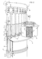
- Number 1 in Figure 1 indicates as a whole a labelling machine for applying labels 2 ( Figures 2 and 3 ) to respective articles or more specifically containers, particularly bottles 3, each of which ( Figures 1 to 3 ) has a given longitudinal axis A, is bonded at the bottom by a bottom wall 4 substantially perpendicular to axis A, and has a top neck 5 substantially coaxial with axis A.
- Machine 1 comprises a conveying device that serves to bend and weld labels 2 in a tubular configuration ( Figure 3 ) and to produce insertion of bottles 3 into the so formed tubular labels 2.
- the conveying device comprises a carousel 7, which is mounted to rotate continuously (anticlockwise in Figure 1 ) about a respective vertical axis B perpendicular to the plane of Figure 1 .
- the carousel 7 receives a succession of unlabelled bottles 3 from an input wheel 8, which cooperates with carousel 7 at a first transfer station 9 and is mounted to rotate continuously (clockwise in Figure 1 ) about a respective longitudinal axis C parallel to axis B.
- the carousel 7 also receives a succession of rectangular or square labels 2 from an input drum 10, which cooperates with carousel 7 at a second transfer station 11 and is mounted to rotate continuously about a respective longitudinal axis D parallel to axes B and C.
- the carousel 7 releases a succession of labelled bottles 3 to an output wheel 12, which cooperates with carousel 7 at a third transfer station 13 and is mounted to rotate continuously (clockwise in Figure 1 ) about a respective longitudinal axis E parallel to axes B, C and D.
- transfer station 11 is arranged, along path P, downstream from transfer station 9 and upstream from transfer station 13.
- the carousel 7 comprises a number of operating or labelling units 15, which are equally spaced about axis B, are mounted along a peripheral edge of carousel 7, and are moved by carousel 7 along a circular path P extending about axis B and through transfer stations 9, 11 and 13.
- the units 15 are secured to a horizontal rotary table 14 of carousel 7, have respective axes F parallel to axes B, C, D, E and extend coaxially through respective holes 16 of the rotary table 14 and on both sides of such table.
- Each unit 15 is adapted to receive a relative bottle 3 from input wheel 8 in a vertical position, i.e. coaxially with the relative axis F, and to hold said bottle 3 in such position along path P from transfer station 9 to transfer station 13.
- Units 15 being all identical to each other, only one of them is described herebelow for the sake of simplicity and clarity; it shall be apparent that the features described hereafter with reference to one labelling unit 15 are common to all of them.
- labelling unit 15 comprises, above the rotary table 14 of carousel 7, a supporting assembly 17 adapted to support the bottom wall 4 of a relative bottle 3 and an upper retainer 18 adapted to cooperate with the top neck 5 of the bottle 3.
- supporting assembly 17 comprises:
- the bottle 3 rests on a support plate 21 (only dimly visible in Figures 2 and 3 ), which is carried by top end 23 of movable member 22 through interposition of a relative bearing (not visible), so as to be rotatably independent of movable member 22.
- a support plate 21 (only dimly visible in Figures 2 and 3 )
- a relative bearing (not visible)
- Movable member 22 can be moved along axis F between a fully retracted position within the relative supporting mount 20 and a raised position ( Figures 2 and 3 ).
- movable member 22 In the fully retracted position, movable member 22 is completely housed within the relative supporting mount 20 so that support plate 21 is flush with a top surface 25 of the supporting mount 20.
- movable member 22 protrudes from the top surface 25 of the supporting mount 20 and is adapted to receive, on its lateral surface 24, a relative label 2 from input drum 10.
- labels 2 are cut in a known manner from a web 26 ( Figure 1 ) by a cutting device 27 (only schematically shown in Figure 1 ) and fed to input drum 10 to be then transferred to the relative movable members 22 in the raised position.
- the cut labels 2 are retained on a lateral surface 30 of input drum 10 by suction; in fact, the lateral surface 30 of input drum 10 is divided into a given number - three in the embodiment shown - of suction regions 31, which are equally spaced about axis D, are each provided with a plurality of through holes 32 connected to a pneumatic suction device (known per se and not shown) and are adapted to cooperate with respective labels 2.
- a pneumatic suction device known per se and not shown
- the lateral surface 24 of the movable member 22 is provided with a plurality of through holes 33, in turn connected to a pneumatic suction device (known per se and not shown) so as to retain the relative label 2 by suction.
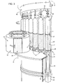
- movable member 22 can be rotated about the relative axis F in order to produce the complete wrapping of the relative label 2, coming from input drum 10, on lateral surface 24. More specifically, each label 2, fed by input drum 10, is wrapped around the relative movable member 22 in the raised position so as to form a cylinder with opposite vertical edges 34 overlapping one another.
- movable member 22 is subjected to distinct movements in different operative steps of the labelling machine 1:
- motor 35 is arranged underneath rotary table 14 and is secured to a bottom surface of the rotary table 14 through the interposition of a further hollow supporting mount 38 of axis F.
- the supporting mount 38 has one end 39 secured to the bottom surface of the rotary table 14 around the relative hole 16 and coaxially with supporting mount 20, and an opposite end 40, from which motor 35 coaxially projects downwards.
- driving shaft 36 extends coaxially through motor 35, supporting mounts 20, 38 and hole 16 of rotary table 14; more specifically, driving shaft 36 is angularly and axially fastened to movable member 22, is angularly coupled to motor 35 and is supported by such motor 35 in an axially free manner.
- unit 15 comprises first transmission means 90 for angularly coupling motor 35 and driving shaft 36.
- driving shaft 36 comprises a screw portion 43 which is defined by an externally threaded surface 45 provided on a longitudinal region of driving shaft 36. Furthermore, driving shaft 36 has (see, in particular, Figure 6 ) a plurality of longitudinal grooves 91 provided on the externally threaded surface 45 and extending at least over the whole of said screw portion 43.
- grooves 91 are angularly equally spaced about the axis of driving shaft 36.
- driving shaft 36 comprises three longitudinal grooves 91 spaced apart from one another of 120°.
- First transmission means 90 are axially fixed relative to rotary table 14 through supporting mount 38, whilst being at a time rotatable relative to axis F of supporting mount 38. More particularly, first transmission means 90 comprise a collet 92 internally provided with a plurality of ribs (not shown) for engaging and cooperating with the relative longitudinal grooves 91 of driving shaft 36.
- the ribs shall also preferably be angularly equally spaced about the axis of collet 92 and in a number corresponding to the number of longitudinal grooves 91.
- collet 92 is fastened, e.g. releasably, to the rotor of motor 35.
- collet 92 is likewise releasably fastened to an axial coupling portion 93 of first transmission means 90.
- the axial coupling portion 93 is rotatable over a corresponding first axial coupling portion 38a of supporting mount 38.
- first transmission means 90 are radially fixed with respect to supporting mount 38 and, consequently, to rotary table 14.
- the unit 15 further comprises second transmission means 41, which can be selectively actuated to transform the rotational movement imparted by motor 35 to driving shaft 36 in a resulting movement of the relative movable member 22 having a translational component along axis F, said second transmission means 41 being radially fixed with respect to the supporting mount 38 and, consequently, to rotary table 14.
- the second transmission means 41 are movable between a first axial position wherein they are kinematically integral with the first transmission means 90 and a second axial position wherein they are kinematically independent of the first transmission means 90 and integral with supporting mount 38 and, consequently, with rotary table 14.
- second transmission means 41 comprise a tubular lead screw member 42, which internally engages with the screw portion 43 of driving shaft 36.
- second transmission means 41 comprise an axial coupling portion 94 to which lead screw member 41 is directly or indirectly releasably fastened.
- the axial coupling portion 94 is rotatable over a corresponding second axial coupling portion 38b of supporting mount 38.
- the axial coupling portion 94 of second transmission means 41 is arranged between the second axial coupling portion 38b and the axial coupling portion 93 of first transmission means 90.
- second transmission means 41 are movable between a first axial position wherein they are kinematically integral with the axial coupling portion 93 of first transmission means 90 and a second axial position wherein they are kinematically independent of the first transmission means 90 and kinematically integral with the second axial coupling portion 38b and, therefore, with supporting mount 38 (i.e. with rotary table 14).
- second transmission means 41 When second transmission means 41 are in the first axial position, they are kinematically integral with the first transmission means 90, hence they shall rotate integrally with driving shaft 36 when the latter is driven to rotate by motor 35.
- second transmission means 41 are in the second axial position, they are kinematically integral with supporting mount 38 and the rotary table 14. As a consequence, through cooperation of the screw portion 43 of driving shaft 35 with the lead screw 43 of second transmission means 41, transformation of the pure rotational movement imparted by motor 35 to the driving shaft 36 into a rotational-translational movement of the same shaft 36 along axis F is obtained.
- Movable member 22 being axially connected with driving shaft 36, translational movement of movable member 22 along axis F is also produced.
- displacement of the second transmission means 41 between the relative first and second axial positions may be achieved by selective actuation of electromagnetic means.
- first and second axial coupling portions 38a and 38b may advantageously consist of independently and selectively actuatable electromagnets, the axial coupling portion 94 of second transmission means 41 being made of a material capable of being attracted by an electromagnet.
- movement of second transmission means 41 may be obtained by pneumatic means, or by means of cams and the like.
- the pure rotational movement of driving shaft 36 and the relative movable member 22 about axis F is obtained by maintaining second transmission means 41 in the first axial position wherein they are also driven to rotate with the driving shaft 36, the rotational movement being transmitted to the second transmission means 41 through collet 92 and the axial coupling portion 93 of first transmission means 90, with which they are maintained kinematically integral.
- Kinematic coupling of second transmission means 41 and first transmission means 90 is preferably achieved through activation of the electromagnet of the first axial coupling portion 38a of supporting mount 38.
- the translational movement of driving shaft 36 and the relative movable member 22 along axis F is obtained by maintaining the second transmission means in the second axial position wherein they are kinematically independent of the first transmission means 90 and angularly and axially integral supporting mount 38 and rotary table 14.
- Kinematic uncoupling of second transmission means 41 relative to first transmission means 90 is preferably achieved through activation of the electromagnet of the second axial coupling portion 38b of supporting mount 38.
- the driving shaft 36 is alternatively operatively coupled with first transmission means 90 alone (when second transmission means 41 are in the first axial position) with both first and second transmission means 90, 41 (when second transmission means are in the second axial position).
- the retainer 18, corresponding to the described supporting assembly 17 comprises, in a known manner, a cylindrical movable member 65, which protrudes vertically from an upper rotary portion 66 of carousel 7, can be displaced along the relative axis F and has a bell-shaped free end portion 67 adapted to cooperate with the top neck 5 of the bottle 3 carried by such supporting assembly 17.
- each movable member 65 is controlled in a known manner so as to maintain the same distance between its end portion 67 and the corresponding plate 21, during the movement of the relative unit 15 along the portion of path P from transfer station 9 to transfer station 13, and to increase such distance at transfer stations 9, 13 and during the portion of path P from station 13 to station 9.
- bottles 3 are securely hold in their vertical positions during the travel from station 9 to station 13 and are free to be transferred at such stations 9 and 13 from input wheel 8 and to output wheel 12, respectively.
- labelling machine 1 further comprises a plurality of welding devices 70, each of which arranged in front of, and in a radially inner position than, the relative unit 15 and adapted to cooperate, in a known manner, with the label 2 wrapped around the corresponding movable member 22 for welding the overlapped edges 34 and to produce a tubular configuration of such label.
- the downward movement of the relative movable member 22 towards the fully retracted position within the relative supporting mount 20 produces the insertion of the relative bottle 3 inside said tubular label.
- the so formed labelled bottle 3 is then fed to a shrinking tunnel (known per se and not shown), where shrinking and adhesion of the label 2 to the external surface of the bottle 3 occurs.
- angle ⁇ refers to the lifting movement of the movable members 22 from the fully retracted position to the raised position
- angle ⁇ refers to the label transfer from the input drum 10 to the relative movable member 22
- angle ⁇ refers to the welding operation on the overlapped edges 34 of the tubular labels 2
- angle ⁇ refers to the downward movement of the movable members 22 to produce insertion of the bottles 3 within the corresponding tubular labels 2.
- machine 1 Operation of machine 1 will now be described with reference to the labelling of one bottle 3, and therefore to one labelling unit 15, and as of the instant in which the movable member 22 of said unit 15 is in the fully retracted position within the relative supporting mount 20 and has just received the unlabelled bottle 3 from input wheel 8.
- the second transmission means 41 are moved to their second axial position, preferably through activation of the electromagnet of the second axial coupling portion 38b of supporting mount 38, and the motor 35 is actuated. Thanks to the coupling between the lead screw member 42 of the second transmission means 41 and driving shaft 36, the lead screw member 42 being kinematically integral with the rotary table 14, the driving shaft 36 moves along and about axis F thereby producing a corresponding rotational-translational movement of the movable member 22 towards the desired raised position.
- the input drum 10 reaches an angular position around axis D adapted to put the label 2 into contact with the movable member 22 passing through such station; in this condition (angle ⁇ ), a pure rotational movement of movable member 22 around axis F is required to produce complete wrapping of the label 2 in a known manner around such movable member 22 ( Figure 3 ). More specifically, the label 2 reaches a cylindrical configuration with the opposite vertical edges 34 overlapped one another.
- the second transmission means 41 are moved to their first axial position, preferably through activation of the electromagnet of the first axial coupling portion 38a of supporting mount 38, and the motor 35 is actuated.
- the second transmission means 41 having thus been made kinematically integral with the first transmission means 90, a purely rotational movement is imparted by the motor 35 to the driving shaft 36. Said purely rotational movement is thus transferred to the movable member 22.
- the sleeve element which is axially locked between the seat of motor 35 and end 40 of supporting mount 38, prevents any displacement of driving shaft 36 along axis F.
- the label 2 is ready to be welded along the edges 34 by activation of the welding device 70 (angle Y).
- the movable member 22 must be returned to the fully retracted position within the relative supporting mount 20, so as to produce the insertion of the bottle 3 inside the so formed tubular label 2.
- This movement is once again obtained by moving the second transmission means 41 into their second axial position, preferably through activation of the electromagnet of the second axial coupling portion 38b of supporting mount 38, and by actuating motor 35 in the direction opposite the one for producing the upward movement of the driving shaft 36 and the movable member 22.
- Heat-shrinking (the implementation of which is not illustrated) can be subsequently performed on the bottles 3 exiting the carousel 7 to cause shrinking and adhesion of the label 2 to the external surface of the relative bottle.
- the new solution makes it possible to use one single motor 35 for controlling both rotational and translational movements of each movable member 22.
- cam means for lifting and lowering movable members 22 are no longer necessary, whereby a significant reduction of costs for the manufacture of the labelling machine 1 is achieved.
- the height of the movable member 22 protruding from the relative supporting mount 20 can be set in accordance with the height of the processed labels 2 simply by controlling the time of actuation of the motor 35.
- the labelling units 15 makes it possible to apply a large variety of labels 2 of different heights to respective bottles 3 without requiring that machine parts, such as fixed cam means, be replaced with every change in label height.
- first and second transmission means 90 and 41 require only a small displacement of parts of the labelling unit 15 along the axial direction, which means that radial encumbrance of the labelling unit 15 is kept at a minimum.
- both first and second transmission means 90 and 41 operatively engage the same portion of driving shaft 36 - namely the screw portion 43 which is, by design and construction, adapted to engage with both transmission means, in that it is provided with both longitudinal grooves and screwed outer surface - also the overall vertical encumbrance of labelling unit 15 is advantageously restrained.
Description
- The present invention relates to a unit for applying a label on a relative article according to the preamble of
claim 1. More particularly, the invention refers to a unit for applying a label made from heat-shrinking film on a bottle - or other generic container - which the following description will refer to, although this is in no way intended to limit the scope of protection as defined by the accompanying claims. - As it is generally known, labelling machines are used to apply labels to containers or articles of all sorts. Typically used with beverage bottles or vessels are tubular labels (commonly called "sleeve labels"), which are obtained by:
- cutting a web unwound from a supply roll into a plurality of rectangular or square labels;
- bending each label in a cylindrical configuration such that opposite vertical edges thereof overlap one another; and
- welding the overlapped edges of each cylindrically configured label.
- A particular type of labelling machine is known which serves to bend and weld labels in a tubular configuration and to produce insertion of containers into the thus formed tubular labels. This type of machine basically comprises a carousel rotating about a vertical axis to define a circular path, along which a succession of unlabelled containers is received. Furthermore, this machine is designed to receive a corresponding succession of rectangular or square labels from respective input wheels; to produce application of the labels in a tubular configuration onto respective containers; and to release the labelled containers to an output wheel.
- More specifically, the carousel comprises a number of labelling units which are equally spaced about the rotation axis, are mounted along a peripheral edge of the carousel and are moved by the latter along the above-mentioned circular path.
- Each labelling unit comprises a bottom supporting assembly adapted to support the bottom wall of a relative container and an upper retainer adapted to cooperate with the top portion of such container to hold it in a vertical position as the carousel rotates about the vertical axis.
- Each supporting assembly comprises a vertical hollow supporting mount, secured to a horizontal plane of a rotary frame of the carousel, and a cylindrical movable member, engaging the supporting mount in sliding and rotating manner with respect to its axis, and adapted to carry a relative container on its top surface and a relative label on its lateral surface.
- Each movable member can be displaced between a raised position and a fully retracted position within the relative supporting mount.
- In the raised position, each movable member protrudes from a top surface of the relative supporting mount and is adapted to receive a relative label on its lateral surface from the label input wheel; in particular the label is wrapped around the movable member such that opposite vertical edges of the label overlap one another.
- In order to produce this complete wrapping, the movable member is rotated about its axis during the transfer of the label from the label input wheel.
- In the fully retracted position, which is reached at the container input and output wheels, the top surface of each movable member is flush with the top surface of the supporting mount so that containers are transferred onto and from the carousel along the same transfer plane.
- After welding of the overlapped edges of a tubular label, the displacement of the relative movable member from the raised position to the fully retracted position produces the insertion of the relative container inside the label, making the thus obtained labeled container ready to be transferred to the output wheel.
- To summarize, as the carousel rotates about the vertical axis, in different operative steps of the labelling machine each movable member is:
- axially displaced from the fully retracted position to the raised position, after a container has been transferred to (i.e. fed into) the relative labelling unit;
- rotated about its axis to receive a relative label from the label input wheel and to allow bending of said label into the desired cylindrical or tubular configuration; and
- axially displaced from the raised position to the fully retracted position to allow insertion of the container within the label welded in the tubular configuration.
- Currently, the rotational movement of each movable member is controlled by an electric motor, whilst the translational motion of said movable member is obtained through use of a cam having a given profile.
- This solution has the drawback that the cam profile needs to be changed every time the height of the processed labels varies, which results in high costs and long replacement times.
-
WO 2010/040337 discloses a labelling unit as defined in the preamble ofclaim 1. - It is an object of the present invention to provide a labelling unit which makes it possible to overcome the above drawback in straightforward and inexpensive fashion.
- This object is achieved by a labelling unit as claimed in
claim 1. - A non-limiting embodiment of the present invention will be described in the following by way of example and with reference to the accompanying drawings, in which:
-
Figure 1 shows a schematic plan view, with parts removed for clarity, of a labelling machine provided with a plurality of labelling units in accordance with the teachings of the present invention; -
Figures 2 and3 show larger-scale views in perspective of some labelling units of theFigure 1 labelling machine in proximity of a label transfer station; -
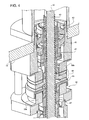
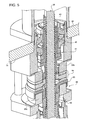
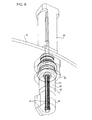
Figures 4 and5 show a larger-scale sectional view in perspective of a detail of a labelling unit according to the present invention in two different operative conditions; and -
Figure 6 shows a larger-scale view in perspective, with parts removed for clarity, of another detail of the labelling unit ofFigures 1 to 5 . -
Number 1 inFigure 1 indicates as a whole a labelling machine for applying labels 2 (Figures 2 and3 ) to respective articles or more specifically containers, particularlybottles 3, each of which (Figures 1 to 3 ) has a given longitudinal axis A, is bonded at the bottom by abottom wall 4 substantially perpendicular to axis A, and has atop neck 5 substantially coaxial with axis A. -
Machine 1 comprises a conveying device that serves to bend andweld labels 2 in a tubular configuration (Figure 3 ) and to produce insertion ofbottles 3 into the so formedtubular labels 2. - In the preferred embodiment as illustrated in the Figures, the conveying device comprises a
carousel 7, which is mounted to rotate continuously (anticlockwise inFigure 1 ) about a respective vertical axis B perpendicular to the plane ofFigure 1 . - The
carousel 7 receives a succession ofunlabelled bottles 3 from aninput wheel 8, which cooperates withcarousel 7 at afirst transfer station 9 and is mounted to rotate continuously (clockwise inFigure 1 ) about a respective longitudinal axis C parallel to axis B. - The
carousel 7 also receives a succession of rectangular orsquare labels 2 from aninput drum 10, which cooperates withcarousel 7 at asecond transfer station 11 and is mounted to rotate continuously about a respective longitudinal axis D parallel to axes B and C. - The
carousel 7 releases a succession of labelledbottles 3 to anoutput wheel 12, which cooperates withcarousel 7 at athird transfer station 13 and is mounted to rotate continuously (clockwise inFigure 1 ) about a respective longitudinal axis E parallel to axes B, C and D. - As shown in
Figure 1 ,transfer station 11 is arranged, along path P, downstream fromtransfer station 9 and upstream fromtransfer station 13. - The
carousel 7 comprises a number of operating or labellingunits 15, which are equally spaced about axis B, are mounted along a peripheral edge ofcarousel 7, and are moved bycarousel 7 along a circular path P extending about axis B and throughtransfer stations - With reference to
Figures 2 to 6 , theunits 15 are secured to a horizontal rotary table 14 ofcarousel 7, have respective axes F parallel to axes B, C, D, E and extend coaxially throughrespective holes 16 of the rotary table 14 and on both sides of such table. - Each
unit 15 is adapted to receive arelative bottle 3 frominput wheel 8 in a vertical position, i.e. coaxially with the relative axis F, and to hold saidbottle 3 in such position along path P fromtransfer station 9 totransfer station 13. -
Units 15 being all identical to each other, only one of them is described herebelow for the sake of simplicity and clarity; it shall be apparent that the features described hereafter with reference to one labellingunit 15 are common to all of them. - In particular,
labelling unit 15 comprises, above the rotary table 14 ofcarousel 7, a supportingassembly 17 adapted to support thebottom wall 4 of arelative bottle 3 and anupper retainer 18 adapted to cooperate with thetop neck 5 of thebottle 3. - In particular, supporting
assembly 17 comprises: - a hollow supporting
mount 20 of axis F, which is secured to a top surface of rotary table 14 around the relative hole; and - a cylindrical
movable member 22, engaging the supportingmount 20 in sliding and rotating fashion with respect to axis F, and adapted to carry coaxially arelative bottle 3 on itstop end 23 and arelative label 2 on itslateral surface 24. - More specifically, the
bottle 3 rests on a support plate 21 (only dimly visible inFigures 2 and3 ), which is carried bytop end 23 ofmovable member 22 through interposition of a relative bearing (not visible), so as to be rotatably independent ofmovable member 22. Thus, rotational movements ofmovable member 22 around axis F are not transmitted to thebottle 3. -
Movable member 22 can be moved along axis F between a fully retracted position within the relative supportingmount 20 and a raised position (Figures 2 and3 ). - In the fully retracted position,
movable member 22 is completely housed within the relative supportingmount 20 so thatsupport plate 21 is flush with atop surface 25 of the supportingmount 20. - In the raised position,
movable member 22 protrudes from thetop surface 25 of the supportingmount 20 and is adapted to receive, on itslateral surface 24, arelative label 2 frominput drum 10. - More specifically
labels 2 are cut in a known manner from a web 26 (Figure 1 ) by a cutting device 27 (only schematically shown inFigure 1 ) and fed to inputdrum 10 to be then transferred to the relativemovable members 22 in the raised position. - As shown in
Figures 2 and3 , thecut labels 2 are retained on alateral surface 30 ofinput drum 10 by suction; in fact, thelateral surface 30 ofinput drum 10 is divided into a given number - three in the embodiment shown - ofsuction regions 31, which are equally spaced about axis D, are each provided with a plurality of throughholes 32 connected to a pneumatic suction device (known per se and not shown) and are adapted to cooperate withrespective labels 2. - In a completely analogous manner, the
lateral surface 24 of themovable member 22 is provided with a plurality of throughholes 33, in turn connected to a pneumatic suction device (known per se and not shown) so as to retain therelative label 2 by suction. - At the
transfer station 11,movable member 22 can be rotated about the relative axis F in order to produce the complete wrapping of therelative label 2, coming frominput drum 10, onlateral surface 24. More specifically, eachlabel 2, fed byinput drum 10, is wrapped around the relativemovable member 22 in the raised position so as to form a cylinder with oppositevertical edges 34 overlapping one another. - To summarize, while being advanced along path P with the other components of
unit 15,movable member 22 is subjected to distinct movements in different operative steps of the labelling machine 1: - a displacement along axis F from the fully retracted position to the raised position, after a
bottle 3 has been transferred tounit 15; - a rotational movement about axis F to receive a
relative label 2 frominput drum 10 and to allow bending of said label in the cylindrical/tubular configuration; and - a displacement from the raised position to the fully retracted position to allow insertion of the
bottle 3 within thelabel 2 welded in the tubular configuration. - All the above distinct movements are obtained basically through an electric motor 35 (
Figure 6 ), carried by the rotary table 14, and a drivingshaft 36 coaxially coupled to themovable member 22 and actuated by themotor 35. - In particular,
motor 35 is arranged underneath rotary table 14 and is secured to a bottom surface of the rotary table 14 through the interposition of a further hollow supportingmount 38 of axis F. More specifically, the supportingmount 38 has oneend 39 secured to the bottom surface of the rotary table 14 around therelative hole 16 and coaxially with supportingmount 20, and anopposite end 40, from which motor 35 coaxially projects downwards. - As shown in
Figures 4 to 6 , drivingshaft 36 extends coaxially throughmotor 35, supportingmounts hole 16 of rotary table 14; more specifically, drivingshaft 36 is angularly and axially fastened tomovable member 22, is angularly coupled tomotor 35 and is supported bysuch motor 35 in an axially free manner. - More particularly,
unit 15 comprises first transmission means 90 forangularly coupling motor 35 and drivingshaft 36. - As shown in greater detail in
Figures 4 and5 , drivingshaft 36 comprises ascrew portion 43 which is defined by an externally threadedsurface 45 provided on a longitudinal region of drivingshaft 36. Furthermore, drivingshaft 36 has (see, in particular,Figure 6 ) a plurality oflongitudinal grooves 91 provided on the externally threadedsurface 45 and extending at least over the whole of saidscrew portion 43. - Preferably,
grooves 91 are angularly equally spaced about the axis of drivingshaft 36. By way of example, in the embodiment shown in the accompanying Figures, drivingshaft 36 comprises threelongitudinal grooves 91 spaced apart from one another of 120°. - First transmission means 90 are axially fixed relative to rotary table 14 through supporting
mount 38, whilst being at a time rotatable relative to axis F of supportingmount 38. More particularly, first transmission means 90 comprise acollet 92 internally provided with a plurality of ribs (not shown) for engaging and cooperating with the relativelongitudinal grooves 91 of drivingshaft 36. - It shall be apparent that the ribs shall also preferably be angularly equally spaced about the axis of
collet 92 and in a number corresponding to the number oflongitudinal grooves 91. - At its bottom end,
collet 92 is fastened, e.g. releasably, to the rotor ofmotor 35. At its top end,collet 92 is likewise releasably fastened to anaxial coupling portion 93 of first transmission means 90. Theaxial coupling portion 93 is rotatable over a corresponding firstaxial coupling portion 38a of supportingmount 38. - Advantageously, first transmission means 90 are radially fixed with respect to supporting
mount 38 and, consequently, to rotary table 14. - Advantageously, the
unit 15 further comprises second transmission means 41, which can be selectively actuated to transform the rotational movement imparted bymotor 35 to drivingshaft 36 in a resulting movement of the relativemovable member 22 having a translational component along axis F, said second transmission means 41 being radially fixed with respect to the supportingmount 38 and, consequently, to rotary table 14. - More particularly, the second transmission means 41 are movable between a first axial position wherein they are kinematically integral with the first transmission means 90 and a second axial position wherein they are kinematically independent of the first transmission means 90 and integral with supporting
mount 38 and, consequently, with rotary table 14. - With reference to
Figures 4 and5 , second transmission means 41 comprise a tubularlead screw member 42, which internally engages with thescrew portion 43 of drivingshaft 36. - Furthermore, second transmission means 41 comprise an
axial coupling portion 94 to whichlead screw member 41 is directly or indirectly releasably fastened. Theaxial coupling portion 94 is rotatable over a corresponding secondaxial coupling portion 38b of supportingmount 38. - In particular, the
axial coupling portion 94 of second transmission means 41 is arranged between the secondaxial coupling portion 38b and theaxial coupling portion 93 of first transmission means 90. - In practice, in the embodiment shown in the Figures, second transmission means 41 are movable between a first axial position wherein they are kinematically integral with the
axial coupling portion 93 of first transmission means 90 and a second axial position wherein they are kinematically independent of the first transmission means 90 and kinematically integral with the secondaxial coupling portion 38b and, therefore, with supporting mount 38 (i.e. with rotary table 14). - When second transmission means 41 are in the first axial position, they are kinematically integral with the first transmission means 90, hence they shall rotate integrally with driving
shaft 36 when the latter is driven to rotate bymotor 35. - On the other hand, when second transmission means 41 are in the second axial position, they are kinematically integral with supporting
mount 38 and the rotary table 14. As a consequence, through cooperation of thescrew portion 43 of drivingshaft 35 with thelead screw 43 of second transmission means 41, transformation of the pure rotational movement imparted bymotor 35 to the drivingshaft 36 into a rotational-translational movement of thesame shaft 36 along axis F is obtained. -
Movable member 22 being axially connected with drivingshaft 36, translational movement ofmovable member 22 along axis F is also produced. - Advantageously, as shall be explained in greater detail in the following, displacement of the second transmission means 41 between the relative first and second axial positions may be achieved by selective actuation of electromagnetic means.
- To this purpose, first and second
axial coupling portions axial coupling portion 94 of second transmission means 41 being made of a material capable of being attracted by an electromagnet. - Alternatively, movement of second transmission means 41 may be obtained by pneumatic means, or by means of cams and the like.
- To summarize, the pure rotational movement of driving
shaft 36 and the relativemovable member 22 about axis F is obtained by maintaining second transmission means 41 in the first axial position wherein they are also driven to rotate with the drivingshaft 36, the rotational movement being transmitted to the second transmission means 41 throughcollet 92 and theaxial coupling portion 93 of first transmission means 90, with which they are maintained kinematically integral. Kinematic coupling of second transmission means 41 and first transmission means 90 is preferably achieved through activation of the electromagnet of the firstaxial coupling portion 38a of supportingmount 38. - Conversely, the translational movement of driving
shaft 36 and the relativemovable member 22 along axis F is obtained by maintaining the second transmission means in the second axial position wherein they are kinematically independent of the first transmission means 90 and angularly and axially integral supportingmount 38 and rotary table 14. Kinematic uncoupling of second transmission means 41 relative to first transmission means 90 is preferably achieved through activation of the electromagnet of the secondaxial coupling portion 38b of supportingmount 38. - In practice, as
unit 15 travels along path P, the drivingshaft 36 is alternatively operatively coupled with first transmission means 90 alone (when second transmission means 41 are in the first axial position) with both first and second transmission means 90, 41 (when second transmission means are in the second axial position). - Coming back now to
Figures 2 and3 , theretainer 18, corresponding to the described supportingassembly 17, comprises, in a known manner, a cylindricalmovable member 65, which protrudes vertically from anupper rotary portion 66 ofcarousel 7, can be displaced along the relative axis F and has a bell-shapedfree end portion 67 adapted to cooperate with thetop neck 5 of thebottle 3 carried by such supportingassembly 17. - More specifically, the displacements of each
movable member 65 are controlled in a known manner so as to maintain the same distance between itsend portion 67 and thecorresponding plate 21, during the movement of therelative unit 15 along the portion of path P fromtransfer station 9 to transferstation 13, and to increase such distance attransfer stations station 13 tostation 9. In this way,bottles 3 are securely hold in their vertical positions during the travel fromstation 9 to station 13 and are free to be transferred atsuch stations input wheel 8 and tooutput wheel 12, respectively. - With reference to
Figure 1 ,labelling machine 1 further comprises a plurality ofwelding devices 70, each of which arranged in front of, and in a radially inner position than, therelative unit 15 and adapted to cooperate, in a known manner, with thelabel 2 wrapped around the correspondingmovable member 22 for welding the overlapped edges 34 and to produce a tubular configuration of such label. - After completion of the welding of a
tubular label 2, the downward movement of the relativemovable member 22 towards the fully retracted position within therelative supporting mount 20 produces the insertion of therelative bottle 3 inside said tubular label. The so formed labelledbottle 3 is then fed to a shrinking tunnel (known per se and not shown), where shrinking and adhesion of thelabel 2 to the external surface of thebottle 3 occurs. - The duration of the most significant operating steps of the
machine 1 is schematically shown inFigure 1 by indicating the corresponding angles of rotation of thecarousel 7 about axis B, along which said steps are performed; in particular, angle α refers to the lifting movement of themovable members 22 from the fully retracted position to the raised position, angle β refers to the label transfer from theinput drum 10 to the relativemovable member 22, angle γ refers to the welding operation on the overlapped edges 34 of thetubular labels 2, and angle δ refers to the downward movement of themovable members 22 to produce insertion of thebottles 3 within the corresponding tubular labels 2. - Operation of
machine 1 will now be described with reference to the labelling of onebottle 3, and therefore to onelabelling unit 15, and as of the instant in which themovable member 22 of saidunit 15 is in the fully retracted position within therelative supporting mount 20 and has just received theunlabelled bottle 3 frominput wheel 8. - In this condition, the
bottle 3, which rests onplate 21 carried by themovable member 22, is held in the vertical position by the combined action of themovable member 22 and the relativeupper retainer 18. - During the subsequent movement of
unit 15 along path P (angle α inFigure 1 ), the second transmission means 41 are moved to their second axial position, preferably through activation of the electromagnet of the secondaxial coupling portion 38b of supportingmount 38, and themotor 35 is actuated. Thanks to the coupling between thelead screw member 42 of the second transmission means 41 and drivingshaft 36, thelead screw member 42 being kinematically integral with the rotary table 14, the drivingshaft 36 moves along and about axis F thereby producing a corresponding rotational-translational movement of themovable member 22 towards the desired raised position. - At the
transfer station 11, theinput drum 10 reaches an angular position around axis D adapted to put thelabel 2 into contact with themovable member 22 passing through such station; in this condition (angle β), a pure rotational movement ofmovable member 22 around axis F is required to produce complete wrapping of thelabel 2 in a known manner around such movable member 22 (Figure 3 ). More specifically, thelabel 2 reaches a cylindrical configuration with the oppositevertical edges 34 overlapped one another. - In order to obtain the above-mentioned rotation, the second transmission means 41 are moved to their first axial position, preferably through activation of the electromagnet of the first
axial coupling portion 38a of supportingmount 38, and themotor 35 is actuated. The second transmission means 41 having thus been made kinematically integral with the first transmission means 90, a purely rotational movement is imparted by themotor 35 to the drivingshaft 36. Said purely rotational movement is thus transferred to themovable member 22. - In practice, the sleeve element, which is axially locked between the seat of
motor 35 and end 40 of supportingmount 38, prevents any displacement of drivingshaft 36 along axis F. - At this point, the
label 2 is ready to be welded along theedges 34 by activation of the welding device 70 (angle Y). - During the last part of the path P (angle δ), the
movable member 22 must be returned to the fully retracted position within therelative supporting mount 20, so as to produce the insertion of thebottle 3 inside the so formedtubular label 2. - This movement is once again obtained by moving the second transmission means 41 into their second axial position, preferably through activation of the electromagnet of the second
axial coupling portion 38b of supportingmount 38, and by actuatingmotor 35 in the direction opposite the one for producing the upward movement of the drivingshaft 36 and themovable member 22. - Heat-shrinking (the implementation of which is not illustrated) can be subsequently performed on the
bottles 3 exiting thecarousel 7 to cause shrinking and adhesion of thelabel 2 to the external surface of the relative bottle. - The advantages of the
labelling units 15 according to the present invention will be clear from the above description. - In particular, the new solution makes it possible to use one
single motor 35 for controlling both rotational and translational movements of eachmovable member 22. As a consequence, cam means for lifting and loweringmovable members 22 are no longer necessary, whereby a significant reduction of costs for the manufacture of thelabelling machine 1 is achieved. - Besides, since the translational movements of each
movable member 22 is produced through actuation ofmotor 35 and not through use of fixed cam means, the height of themovable member 22 protruding from the relative supportingmount 20 can be set in accordance with the height of the processedlabels 2 simply by controlling the time of actuation of themotor 35. In this manner, thelabelling units 15 makes it possible to apply a large variety oflabels 2 of different heights torespective bottles 3 without requiring that machine parts, such as fixed cam means, be replaced with every change in label height. - Furthermore, selective activation of first and second transmission means 90 and 41 requires only a small displacement of parts of the
labelling unit 15 along the axial direction, which means that radial encumbrance of thelabelling unit 15 is kept at a minimum. - On top of that, since both first and second transmission means 90 and 41 operatively engage the same portion of driving shaft 36 - namely the
screw portion 43 which is, by design and construction, adapted to engage with both transmission means, in that it is provided with both longitudinal grooves and screwed outer surface - also the overall vertical encumbrance oflabelling unit 15 is advantageously restrained. - Clearly, changes may be made to labelling
machine 1 andlabelling units 15 as described and illustrated herein without, however, departing from the scope of protection as defined in the accompanying claims.
Claims (14)
- A labelling unit (15) movable along a given path (P) for receiving an article (3) and a label (2) and for applying said label (2) onto said article (3), said unit (15) comprising:- support means (20, 38);- a movable member (22) adapted to carry said article (3) and supported by said support means (20, 38) in a sliding and rotating manner with respect to a given axis (F); and- actuator means (35, 36, 41) for producing distinct movements of said movable member (22) in different operative steps of said labelling unit (15); said distinct movements comprising a pure rotation about said axis (F) and a translation along the same axis (F); said actuator means comprising:- one motor (35);- a driving shaft (36) coaxially coupled to said movable member (22) and actuated by said motor (35) to rotate about said axis (F);- first transmission means (90) for angularly coupling said motor (35) with said driving shaft (36);
characterised in that said actuator means further comprise second transmission means (41) which can be selectively actuated to transform the rotational movement imparted by motor (35) to driving shaft (36) in a resulting movement of the relative movable member (22) having a translational component along said axis (F); said second transmission means (41) being movable between: a first axial position, wherein they are kinematically integral with said first transmission means (90); and a second axial position, wherein they are kinematically independent of said first transmission means (90) and integral with said support means (38). - A unit as claimed in claim 1, wherein said second transmission means (41) are radially fixed with respect to said support means (38).
- A unit as claimed in claim 2, wherein said pure rotation of said movable member (22) around said axis (F) is obtained by moving said second transmission means (41) into their first axial position and actuating said motor (35).
- A unit as claimed in claim 2 or 3, wherein said translation of said movable member (22) along said axis (F) is obtained by moving said second transmission means (41) into their second axial position and actuating said motor (35).
- A unit as claimed in any one of claims 2 to 4, wherein, as unit 15 travels along path P, said driving shaft (36) is alternatively operatively coupled with said first transmission means (90) alone, said second transmission means (41) being in said first axial position, and with both first and second transmission means (90, 41), said second transmission means being in said second axial position.
- A unit as claimed in any one of the foregoing claims, wherein said driving shaft (36) comprises: a screw portion (43) which is defined by an externally threaded surface (45) provided on a longitudinal region of said driving shaft (36); and a plurality of longitudinal grooves (91) provided on said externally threaded surface (45) and extending at least over the whole of said screw portion (43).
- A unit as claimed in any one of the foregoing claims, wherein said first transmission means (90) comprise a collet (92) internally provided with a plurality of ribs (93) for engaging and cooperating with relative longitudinal grooves (91) of driving shaft (36).
- A unit as claimed in claim 7, wherein said collet (92) is fastened to a rotor of said motor (35) and to an axial coupling portion (93) of said first transmission means (90), said axial coupling portion (93) being rotatable over a corresponding first axial coupling portion (38a) of said support means (38).
- A unit as claimed in any one of claims 6 to 8, wherein said second transmission means (41) comprise a tubular lead screw member (42), which is internally fastened to the said screw portion (43) of said driving shaft (36).
- A unit as claimed in claim 9, wherein said second transmission means (41) comprise an axial coupling portion (94) to which said lead screw member (41) is fastened, said axial coupling portion (94) being rotatable over a corresponding second axial coupling portion (38b) of said support means (38).
- A unit as claimed in claim 10, wherein said axial coupling portion (94) of said second transmission means (41) is arranged between said second axial coupling portion (38b) and said axial coupling portion (93) of said first transmission means (90).
- A unit as claimed in any one of the foregoing claims, wherein movement of said second transmission means (41) between said first and second axial positions is achieved by selective actuation of electromagnetic means.
- A unit as claimed in any one of claims 10 to 12, wherein said first and second axial coupling portions (38a, 38b) respectively consist of independently and selectively actuatable electromagnets, the axial coupling portion (94) of said second transmission means (41) being made of a material capable of being attracted by an electromagnet.
- A unit as claimed in any one of the foregoing claims, wherein said support means include at least a fixed hollow supporting mount (20) coaxially crossed by said driving shaft (36) and engaged by said movable member (22).
Applications Claiming Priority (2)
| Application Number | Priority Date | Filing Date | Title |
|---|---|---|---|
| ITTO2011A000104A IT1404050B1 (en) | 2011-02-08 | 2011-02-08 | UNIT FOR THE APPLICATION OF A LABEL ON A RELATED ARTICLE. |
| PCT/EP2012/052153 WO2012107506A1 (en) | 2011-02-08 | 2012-02-08 | A unit for applying a label on a relative article |
Publications (2)
| Publication Number | Publication Date |
|---|---|
| EP2673199A1 EP2673199A1 (en) | 2013-12-18 |
| EP2673199B1 true EP2673199B1 (en) | 2014-12-03 |
Family
ID=43976436
Family Applications (1)
| Application Number | Title | Priority Date | Filing Date |
|---|---|---|---|
| EP12703311.6A Not-in-force EP2673199B1 (en) | 2011-02-08 | 2012-02-08 | A unit for applying a label on a relative article |
Country Status (3)
| Country | Link |
|---|---|
| EP (1) | EP2673199B1 (en) |
| IT (1) | IT1404050B1 (en) |
| WO (1) | WO2012107506A1 (en) |
Family Cites Families (3)
| Publication number | Priority date | Publication date | Assignee | Title |
|---|---|---|---|---|
| JPS5833813B2 (en) * | 1977-12-19 | 1983-07-22 | 東洋ガラス株式会社 | Plastic sleeve manufacturing method and device |
| ITPR20020049A1 (en) * | 2002-08-27 | 2004-02-28 | Simonazzi S P A Gia Sig Simonazzi Spa | PROCEDURE FOR FORMING TUBULAR LABELS IN HEAT-SHRINK FILM AND MACHINE FOR FORMING LABELS AND INSERTING BOTTLES OR CONTAINERS IN GENERAL INSIDE THE FORMED LABELS. |
| WO2010040397A1 (en) * | 2008-10-08 | 2010-04-15 | Sidel S.P.A. | Labelling machine for sleeve labels |
-
2011
- 2011-02-08 IT ITTO2011A000104A patent/IT1404050B1/en active
-
2012
- 2012-02-08 WO PCT/EP2012/052153 patent/WO2012107506A1/en active Application Filing
- 2012-02-08 EP EP12703311.6A patent/EP2673199B1/en not_active Not-in-force
Also Published As
| Publication number | Publication date |
|---|---|
| IT1404050B1 (en) | 2013-11-08 |
| EP2673199A1 (en) | 2013-12-18 |
| WO2012107506A8 (en) | 2012-12-20 |
| WO2012107506A1 (en) | 2012-08-16 |
| ITTO20110104A1 (en) | 2012-08-09 |
Similar Documents
| Publication | Publication Date | Title |
|---|---|---|
| EP2550202B1 (en) | Labelling machine | |
| US7870882B2 (en) | Process and apparatus for forming tubular labels of heat shrinkable film and inserting containers therein | |
| EP2464569B1 (en) | A labelling machine for applying tubular labels to respective articles | |
| US9296507B2 (en) | Vacuum transfer element and method for transferring tubular labels | |
| US9522757B2 (en) | Method and unit for forming tubular lengths of web material particularly in a labelling machine | |
| EP2516277B1 (en) | A unit for applying a label on a relative article | |
| WO2011018807A1 (en) | A unit for applying a label on a relative article | |
| EP2673199B1 (en) | A unit for applying a label on a relative article | |
| EP2883804B1 (en) | A labelling unit for applying a label onto an article | |
| EP2626312B1 (en) | Method and unit for forming tubular lengths of web material, particularly in a labelling machine | |
| US20220250781A1 (en) | Vacuum Drum for a Labeling Unit, and Labeling Unit Comprising a Vacuum Drum of This Type | |
| EP2886475B1 (en) | A labelling unit for applying a label onto an article | |
| US11535413B2 (en) | Vacuum drum for a labeling unit, and labeling unit having a vacuum drum of this type | |
| EP2883805A1 (en) | A labelling unit and a method for applying a label onto a non-cylindrical label receiving portion of an article | |
| WO2011104732A1 (en) | A unit for applying a label on a relative article |
Legal Events
| Date | Code | Title | Description |
|---|---|---|---|
| PUAI | Public reference made under article 153(3) epc to a published international application that has entered the european phase |
Free format text: ORIGINAL CODE: 0009012 |
|
| 17P | Request for examination filed |
Effective date: 20130809 |
|
| AK | Designated contracting states |
Kind code of ref document: A1 Designated state(s): AL AT BE BG CH CY CZ DE DK EE ES FI FR GB GR HR HU IE IS IT LI LT LU LV MC MK MT NL NO PL PT RO RS SE SI SK SM TR |
|
| DAX | Request for extension of the european patent (deleted) | ||
| GRAP | Despatch of communication of intention to grant a patent |
Free format text: ORIGINAL CODE: EPIDOSNIGR1 |
|
| INTG | Intention to grant announced |
Effective date: 20140620 |
|
| GRAS | Grant fee paid |
Free format text: ORIGINAL CODE: EPIDOSNIGR3 |
|
| GRAA | (expected) grant |
Free format text: ORIGINAL CODE: 0009210 |
|
| AK | Designated contracting states |
Kind code of ref document: B1 Designated state(s): AL AT BE BG CH CY CZ DE DK EE ES FI FR GB GR HR HU IE IS IT LI LT LU LV MC MK MT NL NO PL PT RO RS SE SI SK SM TR |
|
| REG | Reference to a national code |
Ref country code: GB Ref legal event code: FG4D |
|
| REG | Reference to a national code |
Ref country code: AT Ref legal event code: REF Ref document number: 699211 Country of ref document: AT Kind code of ref document: T Effective date: 20141215 Ref country code: CH Ref legal event code: EP |
|
| REG | Reference to a national code |
Ref country code: IE Ref legal event code: FG4D |
|
| REG | Reference to a national code |
Ref country code: DE Ref legal event code: R096 Ref document number: 602012004115 Country of ref document: DE Effective date: 20150115 |
|
| REG | Reference to a national code |
Ref country code: FR Ref legal event code: PLFP Year of fee payment: 4 |
|
| REG | Reference to a national code |
Ref country code: NL Ref legal event code: VDEP Effective date: 20141203 |
|
| REG | Reference to a national code |
Ref country code: AT Ref legal event code: MK05 Ref document number: 699211 Country of ref document: AT Kind code of ref document: T Effective date: 20141203 |
|
| PG25 | Lapsed in a contracting state [announced via postgrant information from national office to epo] |
Ref country code: NL Free format text: LAPSE BECAUSE OF FAILURE TO SUBMIT A TRANSLATION OF THE DESCRIPTION OR TO PAY THE FEE WITHIN THE PRESCRIBED TIME-LIMIT Effective date: 20141203 Ref country code: ES Free format text: LAPSE BECAUSE OF FAILURE TO SUBMIT A TRANSLATION OF THE DESCRIPTION OR TO PAY THE FEE WITHIN THE PRESCRIBED TIME-LIMIT Effective date: 20141203 Ref country code: LT Free format text: LAPSE BECAUSE OF FAILURE TO SUBMIT A TRANSLATION OF THE DESCRIPTION OR TO PAY THE FEE WITHIN THE PRESCRIBED TIME-LIMIT Effective date: 20141203 Ref country code: NO Free format text: LAPSE BECAUSE OF FAILURE TO SUBMIT A TRANSLATION OF THE DESCRIPTION OR TO PAY THE FEE WITHIN THE PRESCRIBED TIME-LIMIT Effective date: 20150303 Ref country code: FI Free format text: LAPSE BECAUSE OF FAILURE TO SUBMIT A TRANSLATION OF THE DESCRIPTION OR TO PAY THE FEE WITHIN THE PRESCRIBED TIME-LIMIT Effective date: 20141203 |
|
| REG | Reference to a national code |
Ref country code: LT Ref legal event code: MG4D |
|
| PG25 | Lapsed in a contracting state [announced via postgrant information from national office to epo] |
Ref country code: RS Free format text: LAPSE BECAUSE OF FAILURE TO SUBMIT A TRANSLATION OF THE DESCRIPTION OR TO PAY THE FEE WITHIN THE PRESCRIBED TIME-LIMIT Effective date: 20141203 Ref country code: CY Free format text: LAPSE BECAUSE OF FAILURE TO SUBMIT A TRANSLATION OF THE DESCRIPTION OR TO PAY THE FEE WITHIN THE PRESCRIBED TIME-LIMIT Effective date: 20141203 Ref country code: LV Free format text: LAPSE BECAUSE OF FAILURE TO SUBMIT A TRANSLATION OF THE DESCRIPTION OR TO PAY THE FEE WITHIN THE PRESCRIBED TIME-LIMIT Effective date: 20141203 Ref country code: SE Free format text: LAPSE BECAUSE OF FAILURE TO SUBMIT A TRANSLATION OF THE DESCRIPTION OR TO PAY THE FEE WITHIN THE PRESCRIBED TIME-LIMIT Effective date: 20141203 Ref country code: AT Free format text: LAPSE BECAUSE OF FAILURE TO SUBMIT A TRANSLATION OF THE DESCRIPTION OR TO PAY THE FEE WITHIN THE PRESCRIBED TIME-LIMIT Effective date: 20141203 Ref country code: GR Free format text: LAPSE BECAUSE OF FAILURE TO SUBMIT A TRANSLATION OF THE DESCRIPTION OR TO PAY THE FEE WITHIN THE PRESCRIBED TIME-LIMIT Effective date: 20150304 Ref country code: HR Free format text: LAPSE BECAUSE OF FAILURE TO SUBMIT A TRANSLATION OF THE DESCRIPTION OR TO PAY THE FEE WITHIN THE PRESCRIBED TIME-LIMIT Effective date: 20141203 |
|
| PG25 | Lapsed in a contracting state [announced via postgrant information from national office to epo] |
Ref country code: PT Free format text: LAPSE BECAUSE OF FAILURE TO SUBMIT A TRANSLATION OF THE DESCRIPTION OR TO PAY THE FEE WITHIN THE PRESCRIBED TIME-LIMIT Effective date: 20150403 Ref country code: SK Free format text: LAPSE BECAUSE OF FAILURE TO SUBMIT A TRANSLATION OF THE DESCRIPTION OR TO PAY THE FEE WITHIN THE PRESCRIBED TIME-LIMIT Effective date: 20141203 Ref country code: RO Free format text: LAPSE BECAUSE OF FAILURE TO SUBMIT A TRANSLATION OF THE DESCRIPTION OR TO PAY THE FEE WITHIN THE PRESCRIBED TIME-LIMIT Effective date: 20141203 Ref country code: CZ Free format text: LAPSE BECAUSE OF FAILURE TO SUBMIT A TRANSLATION OF THE DESCRIPTION OR TO PAY THE FEE WITHIN THE PRESCRIBED TIME-LIMIT Effective date: 20141203 Ref country code: EE Free format text: LAPSE BECAUSE OF FAILURE TO SUBMIT A TRANSLATION OF THE DESCRIPTION OR TO PAY THE FEE WITHIN THE PRESCRIBED TIME-LIMIT Effective date: 20141203 |
|
| PG25 | Lapsed in a contracting state [announced via postgrant information from national office to epo] |
Ref country code: IS Free format text: LAPSE BECAUSE OF FAILURE TO SUBMIT A TRANSLATION OF THE DESCRIPTION OR TO PAY THE FEE WITHIN THE PRESCRIBED TIME-LIMIT Effective date: 20150403 Ref country code: PL Free format text: LAPSE BECAUSE OF FAILURE TO SUBMIT A TRANSLATION OF THE DESCRIPTION OR TO PAY THE FEE WITHIN THE PRESCRIBED TIME-LIMIT Effective date: 20141203 |
|
| REG | Reference to a national code |
Ref country code: DE Ref legal event code: R097 Ref document number: 602012004115 Country of ref document: DE |
|
| PG25 | Lapsed in a contracting state [announced via postgrant information from national office to epo] |
Ref country code: LU Free format text: LAPSE BECAUSE OF FAILURE TO SUBMIT A TRANSLATION OF THE DESCRIPTION OR TO PAY THE FEE WITHIN THE PRESCRIBED TIME-LIMIT Effective date: 20150208 |
|
| REG | Reference to a national code |
Ref country code: CH Ref legal event code: PL |
|
| PLBE | No opposition filed within time limit |
Free format text: ORIGINAL CODE: 0009261 |
|
| STAA | Information on the status of an ep patent application or granted ep patent |
Free format text: STATUS: NO OPPOSITION FILED WITHIN TIME LIMIT |
|
| PG25 | Lapsed in a contracting state [announced via postgrant information from national office to epo] |
Ref country code: DK Free format text: LAPSE BECAUSE OF FAILURE TO SUBMIT A TRANSLATION OF THE DESCRIPTION OR TO PAY THE FEE WITHIN THE PRESCRIBED TIME-LIMIT Effective date: 20141203 Ref country code: MC Free format text: LAPSE BECAUSE OF FAILURE TO SUBMIT A TRANSLATION OF THE DESCRIPTION OR TO PAY THE FEE WITHIN THE PRESCRIBED TIME-LIMIT Effective date: 20141203 Ref country code: CH Free format text: LAPSE BECAUSE OF NON-PAYMENT OF DUE FEES Effective date: 20150228 Ref country code: LI Free format text: LAPSE BECAUSE OF NON-PAYMENT OF DUE FEES Effective date: 20150228 |
|
| 26N | No opposition filed |
Effective date: 20150904 |
|
| REG | Reference to a national code |
Ref country code: IE Ref legal event code: MM4A |
|
| REG | Reference to a national code |
Ref country code: FR Ref legal event code: PLFP Year of fee payment: 5 |
|
| PG25 | Lapsed in a contracting state [announced via postgrant information from national office to epo] |
Ref country code: IE Free format text: LAPSE BECAUSE OF NON-PAYMENT OF DUE FEES Effective date: 20150208 |
|
| PG25 | Lapsed in a contracting state [announced via postgrant information from national office to epo] |
Ref country code: SI Free format text: LAPSE BECAUSE OF FAILURE TO SUBMIT A TRANSLATION OF THE DESCRIPTION OR TO PAY THE FEE WITHIN THE PRESCRIBED TIME-LIMIT Effective date: 20141203 |
|
| PG25 | Lapsed in a contracting state [announced via postgrant information from national office to epo] |
Ref country code: BE Free format text: LAPSE BECAUSE OF FAILURE TO SUBMIT A TRANSLATION OF THE DESCRIPTION OR TO PAY THE FEE WITHIN THE PRESCRIBED TIME-LIMIT Effective date: 20141203 |
|
| GBPC | Gb: european patent ceased through non-payment of renewal fee |
Effective date: 20160208 |
|
| PG25 | Lapsed in a contracting state [announced via postgrant information from national office to epo] |
Ref country code: MT Free format text: LAPSE BECAUSE OF FAILURE TO SUBMIT A TRANSLATION OF THE DESCRIPTION OR TO PAY THE FEE WITHIN THE PRESCRIBED TIME-LIMIT Effective date: 20141203 |
|
| REG | Reference to a national code |
Ref country code: FR Ref legal event code: PLFP Year of fee payment: 6 |
|
| PG25 | Lapsed in a contracting state [announced via postgrant information from national office to epo] |
Ref country code: GB Free format text: LAPSE BECAUSE OF NON-PAYMENT OF DUE FEES Effective date: 20160208 |
|
| PGFP | Annual fee paid to national office [announced via postgrant information from national office to epo] |
Ref country code: DE Payment date: 20170119 Year of fee payment: 6 Ref country code: FR Payment date: 20170124 Year of fee payment: 6 |
|
| PG25 | Lapsed in a contracting state [announced via postgrant information from national office to epo] |
Ref country code: HU Free format text: LAPSE BECAUSE OF FAILURE TO SUBMIT A TRANSLATION OF THE DESCRIPTION OR TO PAY THE FEE WITHIN THE PRESCRIBED TIME-LIMIT; INVALID AB INITIO Effective date: 20120208 Ref country code: BG Free format text: LAPSE BECAUSE OF FAILURE TO SUBMIT A TRANSLATION OF THE DESCRIPTION OR TO PAY THE FEE WITHIN THE PRESCRIBED TIME-LIMIT Effective date: 20141203 Ref country code: SM Free format text: LAPSE BECAUSE OF FAILURE TO SUBMIT A TRANSLATION OF THE DESCRIPTION OR TO PAY THE FEE WITHIN THE PRESCRIBED TIME-LIMIT Effective date: 20141203 |
|
| PGFP | Annual fee paid to national office [announced via postgrant information from national office to epo] |
Ref country code: IT Payment date: 20170120 Year of fee payment: 6 |
|
| PG25 | Lapsed in a contracting state [announced via postgrant information from national office to epo] |
Ref country code: TR Free format text: LAPSE BECAUSE OF FAILURE TO SUBMIT A TRANSLATION OF THE DESCRIPTION OR TO PAY THE FEE WITHIN THE PRESCRIBED TIME-LIMIT Effective date: 20141203 |
|
| PG25 | Lapsed in a contracting state [announced via postgrant information from national office to epo] |
Ref country code: MK Free format text: LAPSE BECAUSE OF FAILURE TO SUBMIT A TRANSLATION OF THE DESCRIPTION OR TO PAY THE FEE WITHIN THE PRESCRIBED TIME-LIMIT Effective date: 20141203 |
|
| REG | Reference to a national code |
Ref country code: DE Ref legal event code: R119 Ref document number: 602012004115 Country of ref document: DE |
|
| PG25 | Lapsed in a contracting state [announced via postgrant information from national office to epo] |
Ref country code: AL Free format text: LAPSE BECAUSE OF FAILURE TO SUBMIT A TRANSLATION OF THE DESCRIPTION OR TO PAY THE FEE WITHIN THE PRESCRIBED TIME-LIMIT Effective date: 20141203 |
|
| REG | Reference to a national code |
Ref country code: FR Ref legal event code: ST Effective date: 20181031 |
|
| PG25 | Lapsed in a contracting state [announced via postgrant information from national office to epo] |
Ref country code: DE Free format text: LAPSE BECAUSE OF NON-PAYMENT OF DUE FEES Effective date: 20180901 |
|
| PG25 | Lapsed in a contracting state [announced via postgrant information from national office to epo] |
Ref country code: IT Free format text: LAPSE BECAUSE OF NON-PAYMENT OF DUE FEES Effective date: 20180208 Ref country code: FR Free format text: LAPSE BECAUSE OF NON-PAYMENT OF DUE FEES Effective date: 20180228 |