EP2554440B1 - Airbag mit druckempfindlicher Entlüftung - Google Patents
Airbag mit druckempfindlicher Entlüftung Download PDFInfo
- Publication number
- EP2554440B1 EP2554440B1 EP12275074.8A EP12275074A EP2554440B1 EP 2554440 B1 EP2554440 B1 EP 2554440B1 EP 12275074 A EP12275074 A EP 12275074A EP 2554440 B1 EP2554440 B1 EP 2554440B1
- Authority
- EP
- European Patent Office
- Prior art keywords
- airbag
- gas
- vent
- fabric enclosure
- fabric
- Prior art date
- Legal status (The legal status is an assumption and is not a legal conclusion. Google has not performed a legal analysis and makes no representation as to the accuracy of the status listed.)
- Active
Links
Images


Classifications
-
- B—PERFORMING OPERATIONS; TRANSPORTING
- B60—VEHICLES IN GENERAL
- B60R—VEHICLES, VEHICLE FITTINGS, OR VEHICLE PARTS, NOT OTHERWISE PROVIDED FOR
- B60R21/00—Arrangements or fittings on vehicles for protecting or preventing injuries to occupants or pedestrians in case of accidents or other traffic risks
- B60R21/02—Occupant safety arrangements or fittings, e.g. crash pads
- B60R21/16—Inflatable occupant restraints or confinements designed to inflate upon impact or impending impact, e.g. air bags
- B60R21/23—Inflatable members
- B60R21/239—Inflatable members characterised by their venting means
-
- B—PERFORMING OPERATIONS; TRANSPORTING
- B60—VEHICLES IN GENERAL
- B60R—VEHICLES, VEHICLE FITTINGS, OR VEHICLE PARTS, NOT OTHERWISE PROVIDED FOR
- B60R21/00—Arrangements or fittings on vehicles for protecting or preventing injuries to occupants or pedestrians in case of accidents or other traffic risks
- B60R21/02—Occupant safety arrangements or fittings, e.g. crash pads
- B60R21/16—Inflatable occupant restraints or confinements designed to inflate upon impact or impending impact, e.g. air bags
- B60R21/23—Inflatable members
- B60R21/239—Inflatable members characterised by their venting means
- B60R2021/2395—Inflatable members characterised by their venting means comprising means to control the venting
Definitions
- This invention relates to an airbag for a motor vehicle and in particular to the control the flow of gas from the airbag during deployment.
- Fig.1 it is known to provide a motor vehicle with a passenger airbag 1 having a fabric flexible enclosure 5 that is inflated when deployed by a gas generator (not shown) so as to provide protection for a passenger 6 of a motor vehicle. It is further known to provide a vent 7 in the fabric enclosure 5 to allow gas to escape from the fabric enclosure 5 to limit the maximum pressure within the fabric enclosure and to allow gas to be ejected from the fabric enclosure 5 when the passenger 6 impacts against the airbag 1. It is a problem with such prior art designs that it is difficult to provide a vent 7 that restricts the outflow of gas sufficiently during deployment to prevent under inflation of the fabric enclosure 5 from occurring and yet is sufficiently large to allow gas to be ejected rapidly by the impacting passenger 6 to provide the required degree of compliance. It is a further problem with such prior art designs that hot gas flow from the vent 7 can impinge upon the passenger 6 as indicated by the arrow 'H' on Fig.1 .
- an airbag having a flexible fabric enclosure, a vent in the fabric enclosure to allow gas to selectively escape from the fabric enclosure, and a flow control device comprising a flexible membrane fastened around part of a periphery thereof to the fabric enclosure so as to define a gas flow directing passage connected via the vent to an interior of the fabric enclosure and having a free end through which gas from the interior of the fabric enclosure is selectively vented to atmosphere, the flexible membrane further comprising an end flap portion extending away from the free end of the gas flow directing passage and being positioned to overlie an inner surface of the fabric enclosure prior to deployment of the airbag, the flexible membrane being attached to the fabric enclosure so that the gas flow directing passage directs the flow of gas away from a predicted position of impact of a user of the airbag.
- an airbag of the aforesaid type characterised in that no means are used to secure the end flap portion to the inner surface of the fabric enclosure and that the flexible membrane operates during inflation of the fabric enclosure to allow air to flow into the fabric enclosure if a negative pressure is generated within the fabric enclosure and allows gas to flow out of the fabric enclosure when the pressure in the fabric enclosure exceeds a pre-determined level.
- the fabric enclosure may include an impact surface and the predicted position of impact is located on the impact surface.
- the flexible membrane may be fastened around part of the periphery thereof to the inner surface of the fabric enclosure so as to define the gas flow directing passage, may be fastened in a U-shaped manner to the fabric enclosure to define the gas flow directing passage and may be made from one of a gas impermeable fabric and a low permeability fabric.
- the end flap When the airbag is deployed, the end flap may be pulled by the inflation of the gas flow directing passage through the vent.
- the end flap portion may be pulled by the inflation of the gas flow directing passage through the vent when the pressure of gas exceeds the predetermined level.
- the end flap portion may restrict the flow of gas through the gas flow directing passage until the end flap portion has been fully released from the vent.
- Increasing the length of the flap portion may increase the period of time required to pull the flap portion through the vent.
- the vent may be an elongate vent.
- a passenger airbag 1 having a fabric enclosure in the form of a bag 5 and a gas generator (not shown) to inflate the bag 5.
- the bag 5 includes an impact surface 2 against which a user of the airbag 1 such as a passenger 6 is predicted to impact the airbag 1 during use.
- the airbag 1 has an elongate side vent 17 to allow gas to escape from an interior of the bag 5 when the bag 5 is inflated during deployment of the airbag 1. It will be appreciated that the airbag 1 could also have a second vent on the opposite side of the airbag 1.
- the flow through the vent 17 is controlled by a respective flow control device 10.
- the flow control device 10 is orientated so as to direct any gas exiting through the vent 17 to flow away from the predicted position of impact of the passenger 6. That is to say, the flow of gas is directed away from the passenger 6, as indicated by the arrow 'D' on Fig.2
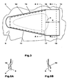
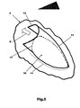
- the flow control device comprises a flexible membrane 10 formed from a gas impermeable or low permeability fabric that is fastened to an inner surface of the bag 5 so as to overlie the elongate vent 17. It will be appreciated that the invention is not limited to the use of fabric for the construction of the flow control device but it is the preferred material due to its availability and flexibility.
- vent 17 is of a teardrop shape as shown in Figs. 2 , 3 and 5 it will be appreciated that the invention is not limited to use with a teardrop shaped vent 17.
- the flexible membrane 10 is secured to the inner surface of the bag 5 by a row of permanent stitches 14 in a U-shaped pattern.
- the stitches 14 extend around part of the periphery of the flexible membrane 10 so as to define a gas flow directing passage 11 that is connected at one end via the vent 17 to an interior of the bag 5 and has a free end through which gas from the interior of the bag 5 is selectively vented to atmosphere as described in more detail hereinafter.
- the width of the flexible membrane material between the locations where it is fastened by means of the stitches 14 is greater than the linear distance between the stitches 14 on opposite sides of the gas flow directing passage 11 so as to provide sufficient free material to inflate to form the gas flow directing passage 11 when the airbag 1 is deployed.
- the flexible membrane 10 could be permanently fastened to the inner surface 9 of the bag 5 by means other than stitching and that the invention is not limited to the use of stitching.
- the flexible membrane 10 also has an end flap portion or tongue 12 extending away from the free end of the gas flow directing passage 11 such that it overlies an inner surface 9 of the bag 5 prior to deployment of the airbag 1.
- the tongue 12 has two longitudinal edges 18 and extends a distance 'X' from one end of the vent 17.
- the magnitude of the distance 'X' determines the time delaying properties of the flow control device, the greater the distance 'X' the longer will it take to achieve full activation of the flow control device. That is to say, if the tongue 12 is longer it will take a longer period of time for it to be drawn out fully through the vent 17.
- the position of the last stitch 14 on each side of the gas flow directing passage 11 relative to the end of the vent 17 and the width between the stitches 14 at that position will vary the pressure required to cause opening of the flow control device. In general terms, if the distance 'Y' from where the stitching ends to the end of the vent 17 is increased the less pressure is required to activate the flow control device. Similarly, if the width between the stiches 14 is increased then the pressure required to activate the flow control device is reduced.
- the shape of the tongue 12 is not limited to a rectangle and that the tongue 12 could be of a different shape to that shown.
- all of the flexible membrane is located within the bag 5 prior to deployment of the airbag 1.
- a vacuum can form in fabric enclosure during the deployment of the airbag due to the fact that the fabric enclosure is expanded rapidly from its containment producing an enclosure volume greater than the volume of gas that has so far been produced by the gas generator. This internal vacuum can cause temporary localised collapsing of the fabric enclosure which may interfere with normal deployment.
- the locally collapsed material may block the vent joining the two chambers so as to prevent correct filling of the secondary chamber.
- Operation of the flow control device is as follows.
- the gas generator which begins to fill the bag 5 until it is fully inflated to a pressure such as for example 20 to 30 kPa which is below a pre-determined pressure of in this case 35kPa. If there is no impact against the bag 5 during this period of time then the vent 17 will remain closed due to the overlying flexible membrane. That is to say, the vent 17 is not opened when a non-impact level of pressure is generated within the bag 5.
- the flow control device can be arranged to open when a normal or desired filling pressure is reached and in this case the predetermined pressure would be equal to the required bag filling pressure.
- Activation of the flow control device comprises the inflation of the gas flow directing passage 11 to such an extent that it begins to pull or drag the tongue 12 out through the vent 17.
- the gas pressure acts directly against the tongue 12 and a small amount of gas can begin to leak or escape from the bag 5. This leakage will continue to increase until eventually the tongue 12 is fully released through the vent 17 at which point gas is free to escape from the gas flow directing passage 11 to atmosphere.
- Activation of the flow control device comprises as before the inflation of the gas flow directing passage 11, and to pulling or dragging of the tongue 12 out through the vent 17 by the inflating gas flow directing passage 11 and in later stages the direct action of the gas pressure against the tongue12.
- the release of gas is a gradual up-ramping process compared to the instantaneous release of gas that occurs if the vent is suddenly fully exposed. Furthermore the time required to pull the tongue 12 out of the vent 17 delays the release of gas by a short period of time such as for example 5 to 10 ms which ensures that the bag 5 does not collapse too quickly after the vent 17 begins to open.
- One advantage of the invention is that because in the preferred embodiment the tongue 12 is not fastened to the bag 5 the pressure required to open the vent 17 is much lower than is the case with a prior art vent closure of the type shown in US Patent 3,527,475 where the frangible fastening means have to be broken to release the flap. Such over pressure is undesirable in that in the case of a release due to occupant impact the bag is harder to compress than if an optimum pressure is used which potentially increases the forces imposed upon the passenger.
- the opening properties of the flow control device can be varied by using materials of differing stiffness to form the flexible membrane.
- the invention provides a flow control device for controlling the flow of gas from a vent of an airbag that is of simple and cost effective construction and provides a number of innovative features. For example, by fastening the flexible membrane to an inner surface of the bag, the bag is self-aspirating and a vacuum will not be generated during inflation of the bag.
- the flow control device can be arranged to open when a required full inflation pressure is reached or only when an occupant impacts against the bag.
- the outflow of hot gas from the bag is directed away from a user of the bag by the gas flow directing passage.
- a large surface area of the flexible membrane is exposed to the gas pressure allowing the use of a low pressure to activate the flow control device.
- the flow control device is tuneable for opening time by varying the dimensions of the tongue.
- the release of gas is a gradual up-ramping not a sudden step change in pressure loss.
- vent area is independent of the flow area of the gas flow directing passage.
- the flow control device will tend to close when the bag pressure falls thereby increasing the working time of the bag.
Landscapes
- Engineering & Computer Science (AREA)
- Mechanical Engineering (AREA)
- Air Bags (AREA)
Claims (10)
- Airbag (1), der Folgendes umfasst: eine flexible Stoffhülle (5), eine Öffnung (17) in der Stoffhülle (5), um zu erlauben, dass Gas wahlweise aus der Stoffhülle (5) entweicht, und eine Durchflusssteuervorrichtung, die eine flexible Membran (10) enthält, die auf einem Teil ihres Umfangs an der Stoffhülle (5) befestigt ist, um einen Gasdurchflusslenkungskanal zu definieren, der durch die Öffnung (17) mit einem Innenraum der Stoffhülle (5) verbunden ist und ein freies Ende besitzt, durch das Gas von innerhalb der Stoffhülle (5) wahlweise an die Atmosphäre abgegeben wird, wobei die flexible Membran (10) ferner einen Endklappenabschnitt (12) aufweist, der sich von dem freien Ende des Gasdurchflusslenkungskanals erstreckt und so positioniert ist, dass er über einer inneren Oberfläche der Stoffhülle (5) liegt, bevor der Airbag (1) entfaltet wird, wobei die flexible Membran (10) an einer inneren Oberfläche (9) der Stoffhülle (5) befestigt ist, so dass der Gasdurchflusslenkungskanal die Strömung von Gas von einer vorgegebenen Auftreffposition eines Anwenders (6) des Airbags (1) weglenkt, dadurch gekennzeichnet, dass keine Mittel verwendet werden, um den Endklappenabschnitt (12) an der inneren Oberfläche der Stoffhülle (5) zu befestigen, und dass die flexible Membran (10) während des Aufblasens der Stoffhülle (5) wirkt, um zuzulassen, dass Luft in die Stoffhülle (5) strömt, falls in der Stoffhülle (5) ein Unterdruck erzeugt wird, und zulässt, dass Gas aus der Stoffhülle (5) strömt, wenn der Druck in der Stoffhülle (5) einen vorgegebenen Pegel überschreitet.
- Airbag (1) nach Anspruch 1, wobei die Stoffhülle (5) eine Auftreffoberfläche (2) aufweist und wobei sich die vorhergesagte Auftreffposition auf der Auftreffoberfläche (2) befindet.
- Airbag (1) nach Anspruch 1 oder Anspruch 2, wobei die flexible Membran längs eines Teils ihres Umfangs an der inneren Oberfläche der Stoffhülle (5) befestigt ist, um den Gasdurchflusslenkungskanal zu definieren.
- Airbag (1) nach einem der Ansprüche 1 bis 3, wobei die flexible Membran (10) U-förmig an der Stoffhülle (5) befestigt ist, um den Gasdurchflusslenkungskanal zu definieren.
- Airbag (1) nach einem der Ansprüche 1 bis 4, wobei die flexible Membran (10) aus einem für Gas undurchlässigen Stoff oder aus einem Stoff mit geringer Durchlässigkeit hergestellt ist.
- Airbag (1) nach einem der Ansprüche 1 bis 5, wobei dann, wenn der Airbag (1) entfaltet wird, der Endklappenabschnitt (12) durch Aufblasen des Gasdurchflusslenkungskanals durch die Öffnung (17) gezogen wird.
- Airbag nach Anspruch 6, wobei der Endklappenabschnitt (12) durch die Öffnung (17) durch das Aufblasen des Gasdurchflusslenkungskanals gezogen wird, wenn der Druck des Gases den vorgegebenen Pegel überschreitet.
- Airbag (1) nach Anspruch 7, wobei der Endklappenabschnitt (12) den Durchfluss von Gas durch den Gasdurchflusslenkungskanal beschränkt, bis der Endklappenabschnitt (12) von der Öffnung (17) vollständig freigegeben worden ist.
- Airbag nach einem der Ansprüche 6 bis 8, wobei die Zunahme der Länge des Klappenabschnitts (12) die Zeitperiode erhöht, die erforderlich ist, um den Klappenabschnitt (12) durch die Öffnung (17) zu ziehen.
- Airbag (1) nach einem der Ansprüche 1 bis 9, wobei die Öffnung (17) eine langgestreckte Öffnung ist.
Applications Claiming Priority (1)
| Application Number | Priority Date | Filing Date | Title |
|---|---|---|---|
| GBGB1113411.1A GB201113411D0 (en) | 2011-08-04 | 2011-08-04 | An airbag having a pressure responsive vent |
Publications (2)
| Publication Number | Publication Date |
|---|---|
| EP2554440A1 EP2554440A1 (de) | 2013-02-06 |
| EP2554440B1 true EP2554440B1 (de) | 2013-10-09 |
Family
ID=44735404
Family Applications (1)
| Application Number | Title | Priority Date | Filing Date |
|---|---|---|---|
| EP12275074.8A Active EP2554440B1 (de) | 2011-08-04 | 2012-05-22 | Airbag mit druckempfindlicher Entlüftung |
Country Status (5)
| Country | Link |
|---|---|
| US (1) | US8573641B2 (de) |
| EP (1) | EP2554440B1 (de) |
| CN (1) | CN102910137B (de) |
| GB (1) | GB201113411D0 (de) |
| RU (1) | RU2588695C2 (de) |
Families Citing this family (13)
| Publication number | Priority date | Publication date | Assignee | Title |
|---|---|---|---|---|
| US9649467B2 (en) * | 2008-01-31 | 2017-05-16 | Syk Technologies, Llc | Nitric oxide reactor and distributor apparatus and method |
| KR101383718B1 (ko) * | 2012-10-10 | 2014-04-10 | 현대자동차(주) | 차량의 외장에어백 쿠션 |
| KR102095564B1 (ko) * | 2013-11-12 | 2020-03-31 | 현대모비스 주식회사 | 에어백 |
| US9580039B2 (en) | 2014-04-22 | 2017-02-28 | Autoliv Asp, Inc. | Multi-chamber airbag with unidirectional vent |
| JP6225877B2 (ja) * | 2014-10-22 | 2017-11-08 | トヨタ自動車株式会社 | 車両用サイドエアバッグ装置 |
| DE102014116433B4 (de) * | 2014-11-11 | 2016-12-08 | Autoliv Development Ab | Gassackanordnung mit einem eine Leitvorrichtung ausbildenden Zuschnitt |
| US9725065B2 (en) * | 2015-04-24 | 2017-08-08 | Ford Global Technologies, Llc | Vehicle airbag with active vent |
| US9533652B1 (en) * | 2015-07-14 | 2017-01-03 | Autoliv Asp, Inc. | One-directional valve for multi-chamber airbags |
| US10293777B2 (en) | 2016-08-26 | 2019-05-21 | Autoliv Asp, Inc. | Multi-cushion airbag assemblies for reducing rotational velocity of an occupant's head |
| CN109131194B (zh) * | 2018-09-21 | 2023-05-02 | 延锋汽车智能安全系统有限责任公司 | 一种顶棚安全气囊 |
| JP7246824B2 (ja) * | 2018-11-13 | 2023-03-28 | 芦森工業株式会社 | エアバッグ装置 |
| CN114866002B (zh) * | 2022-05-20 | 2023-10-31 | 扬州市万佳照明电器有限公司 | 一种风光互补智能路灯 |
| US12496995B2 (en) | 2024-04-11 | 2025-12-16 | Ford Global Technologies, Llc | Vehicle airbag with elastic vent assembly |
Family Cites Families (18)
| Publication number | Priority date | Publication date | Assignee | Title |
|---|---|---|---|---|
| US3527475A (en) | 1969-03-07 | 1970-09-08 | Eaton Yale & Towne | Vehicle safety system |
| DE4101286A1 (de) * | 1991-01-17 | 1992-07-23 | Trw Repa Gmbh | Aufblasbarer gassack fuer rueckhaltesysteme in fahrzeugen |
| US5310215A (en) * | 1993-01-13 | 1994-05-10 | Trw Vehicle Safety Systems Inc. | Apparatus for venting of an inflatable air bag |
| US5542695A (en) * | 1993-12-28 | 1996-08-06 | R. Stresau Laboratory, Inc. | Air bag deployment system |
| US5603526A (en) * | 1996-01-16 | 1997-02-18 | Morton International, Inc. | Pressure vent for air bag cushion |
| JP4423738B2 (ja) * | 2000-03-31 | 2010-03-03 | タカタ株式会社 | エアバッグ |
| FR2825054B1 (fr) * | 2001-05-23 | 2004-10-22 | Aerazur | Dispositif d'orientation des gaz provenant de l'event d'un sac gonflable de securite |
| JP2003327071A (ja) * | 2002-05-10 | 2003-11-19 | Takata Corp | エアバッグ及びエアバッグ装置 |
| DE20209659U1 (de) * | 2002-06-21 | 2002-10-31 | TRW Automotive Safety Systems GmbH & Co. KG, 63743 Aschaffenburg | Gassack |
| WO2005049375A2 (en) * | 2003-11-18 | 2005-06-02 | Tk Holdings, Inc. | Air bag |
| DE102004009013B4 (de) * | 2004-02-25 | 2006-03-16 | Trw Automotive Gmbh | Seitenaufprall-Rückhaltevorrichtung |
| US7325830B2 (en) * | 2005-09-05 | 2008-02-05 | Honda Motor Co., Ltd. | Airbag device for vehicles |
| JP2007145181A (ja) * | 2005-11-28 | 2007-06-14 | Toyoda Gosei Co Ltd | エアバッグ装置 |
| JP2008284930A (ja) * | 2007-05-15 | 2008-11-27 | Toyoda Gosei Co Ltd | エアバッグ装置 |
| JP5251032B2 (ja) * | 2007-08-09 | 2013-07-31 | タカタ株式会社 | エアバッグ及びエアバッグ装置 |
| KR100999804B1 (ko) * | 2007-08-13 | 2010-12-08 | 현대자동차주식회사 | 사이드 에어백 |
| JP4890391B2 (ja) * | 2007-08-24 | 2012-03-07 | 本田技研工業株式会社 | エアバッグ装置 |
| US8590927B2 (en) * | 2010-04-19 | 2013-11-26 | Tk Holdings Inc. | Airbag module |
-
2011
- 2011-08-04 GB GBGB1113411.1A patent/GB201113411D0/en not_active Ceased
-
2012
- 2012-05-22 EP EP12275074.8A patent/EP2554440B1/de active Active
- 2012-07-31 US US13/562,400 patent/US8573641B2/en active Active
- 2012-08-03 RU RU2012133268/11A patent/RU2588695C2/ru not_active IP Right Cessation
- 2012-08-03 CN CN201210276407.8A patent/CN102910137B/zh active Active
Also Published As
| Publication number | Publication date |
|---|---|
| RU2012133268A (ru) | 2014-02-10 |
| US8573641B2 (en) | 2013-11-05 |
| CN102910137A (zh) | 2013-02-06 |
| US20130033024A1 (en) | 2013-02-07 |
| GB201113411D0 (en) | 2011-09-21 |
| CN102910137B (zh) | 2016-06-01 |
| RU2588695C2 (ru) | 2016-07-10 |
| EP2554440A1 (de) | 2013-02-06 |
Similar Documents
| Publication | Publication Date | Title |
|---|---|---|
| EP2554440A1 (de) | Airbag mit druckempfindlicher Entlüftung | |
| CN104981380B (zh) | 具有狭长通气口的安全气囊 | |
| EP2686208B1 (de) | Airbag mit entlüftungsvorrichtung | |
| EP2502794B1 (de) | Fußgänger-Airbaganordnung | |
| US9272685B2 (en) | Air bag with adaptive vent | |
| US9199601B2 (en) | Airbag device | |
| KR101491276B1 (ko) | 에어백 장치 | |
| CN110520333B (zh) | 安全气囊装置 | |
| EP2548772B1 (de) | Airbaganordnung | |
| EP0700809A1 (de) | Kissen mit einem versteckten Volumen | |
| US8905433B2 (en) | Bag-in-bag safety restraint with directional inflation | |
| US20070216146A1 (en) | Airbag cushions with optional venting for out-of-position conditions | |
| CN105109446A (zh) | 具有引导件的被动安全气囊通风口 | |
| CN113226863A (zh) | 安全气囊 | |
| EP3428017B1 (de) | Luftkissenanordnung mit unidirektionalen rückschlagventilen | |
| CN106132786A (zh) | 气囊和用于运行乘客保护系统的方法 | |
| JP2001171456A (ja) | エアバッグ | |
| US7494151B2 (en) | Airbag apparatus with adaptive inflation | |
| KR102685329B1 (ko) | 무릎 에어백 장치 | |
| JP5483586B2 (ja) | エアバッグ装置 | |
| JP4523891B2 (ja) | エアバッグ装置 | |
| KR20170136675A (ko) | 상해 저감형 에어백장치 | |
| KR102928634B1 (ko) | 사이드 에어백 | |
| KR20190044742A (ko) | 에어백 장치 | |
| WO2021002433A1 (ja) | 車両用エアバッグ装置 |
Legal Events
| Date | Code | Title | Description |
|---|---|---|---|
| PUAI | Public reference made under article 153(3) epc to a published international application that has entered the european phase |
Free format text: ORIGINAL CODE: 0009012 |
|
| AK | Designated contracting states |
Kind code of ref document: A1 Designated state(s): AL AT BE BG CH CY CZ DE DK EE ES FI FR GB GR HR HU IE IS IT LI LT LU LV MC MK MT NL NO PL PT RO RS SE SI SK SM TR |
|
| AX | Request for extension of the european patent |
Extension state: BA ME |
|
| 17P | Request for examination filed |
Effective date: 20130307 |
|
| RIC1 | Information provided on ipc code assigned before grant |
Ipc: B60R 21/239 20060101AFI20130326BHEP |
|
| GRAP | Despatch of communication of intention to grant a patent |
Free format text: ORIGINAL CODE: EPIDOSNIGR1 |
|
| INTG | Intention to grant announced |
Effective date: 20130503 |
|
| GRAS | Grant fee paid |
Free format text: ORIGINAL CODE: EPIDOSNIGR3 |
|
| GRAA | (expected) grant |
Free format text: ORIGINAL CODE: 0009210 |
|
| RBV | Designated contracting states (corrected) |
Designated state(s): AL AT BE BG CH CY CZ DE DK EE ES FI FR GB GR HR HU IE IS IT LI LT LU LV MC MK MT NL NO PL PT RO RS SE SI SK SM TR |
|
| AK | Designated contracting states |
Kind code of ref document: B1 Designated state(s): AL AT BE BG CH CY CZ DE DK EE ES FI FR GB GR HR HU IE IS IT LI LT LU LV MC MK MT NL NO PL PT RO RS SE SI SK SM TR |
|
| REG | Reference to a national code |
Ref country code: GB Ref legal event code: FG4D |
|
| REG | Reference to a national code |
Ref country code: AT Ref legal event code: REF Ref document number: 635413 Country of ref document: AT Kind code of ref document: T Effective date: 20131015 Ref country code: CH Ref legal event code: EP |
|
| REG | Reference to a national code |
Ref country code: IE Ref legal event code: FG4D |
|
| REG | Reference to a national code |
Ref country code: DE Ref legal event code: R096 Ref document number: 602012000371 Country of ref document: DE Effective date: 20131205 |
|
| REG | Reference to a national code |
Ref country code: AT Ref legal event code: MK05 Ref document number: 635413 Country of ref document: AT Kind code of ref document: T Effective date: 20131009 |
|
| REG | Reference to a national code |
Ref country code: NL Ref legal event code: VDEP Effective date: 20131009 |
|
| REG | Reference to a national code |
Ref country code: LT Ref legal event code: MG4D |
|
| PG25 | Lapsed in a contracting state [announced via postgrant information from national office to epo] |
Ref country code: LT Free format text: LAPSE BECAUSE OF FAILURE TO SUBMIT A TRANSLATION OF THE DESCRIPTION OR TO PAY THE FEE WITHIN THE PRESCRIBED TIME-LIMIT Effective date: 20131009 Ref country code: NO Free format text: LAPSE BECAUSE OF FAILURE TO SUBMIT A TRANSLATION OF THE DESCRIPTION OR TO PAY THE FEE WITHIN THE PRESCRIBED TIME-LIMIT Effective date: 20140109 Ref country code: NL Free format text: LAPSE BECAUSE OF FAILURE TO SUBMIT A TRANSLATION OF THE DESCRIPTION OR TO PAY THE FEE WITHIN THE PRESCRIBED TIME-LIMIT Effective date: 20131009 Ref country code: BE Free format text: LAPSE BECAUSE OF FAILURE TO SUBMIT A TRANSLATION OF THE DESCRIPTION OR TO PAY THE FEE WITHIN THE PRESCRIBED TIME-LIMIT Effective date: 20131009 Ref country code: FI Free format text: LAPSE BECAUSE OF FAILURE TO SUBMIT A TRANSLATION OF THE DESCRIPTION OR TO PAY THE FEE WITHIN THE PRESCRIBED TIME-LIMIT Effective date: 20131009 Ref country code: HR Free format text: LAPSE BECAUSE OF FAILURE TO SUBMIT A TRANSLATION OF THE DESCRIPTION OR TO PAY THE FEE WITHIN THE PRESCRIBED TIME-LIMIT Effective date: 20131009 Ref country code: IS Free format text: LAPSE BECAUSE OF FAILURE TO SUBMIT A TRANSLATION OF THE DESCRIPTION OR TO PAY THE FEE WITHIN THE PRESCRIBED TIME-LIMIT Effective date: 20140209 Ref country code: SE Free format text: LAPSE BECAUSE OF FAILURE TO SUBMIT A TRANSLATION OF THE DESCRIPTION OR TO PAY THE FEE WITHIN THE PRESCRIBED TIME-LIMIT Effective date: 20131009 |
|
| PG25 | Lapsed in a contracting state [announced via postgrant information from national office to epo] |
Ref country code: CY Free format text: LAPSE BECAUSE OF FAILURE TO SUBMIT A TRANSLATION OF THE DESCRIPTION OR TO PAY THE FEE WITHIN THE PRESCRIBED TIME-LIMIT Effective date: 20131009 Ref country code: ES Free format text: LAPSE BECAUSE OF FAILURE TO SUBMIT A TRANSLATION OF THE DESCRIPTION OR TO PAY THE FEE WITHIN THE PRESCRIBED TIME-LIMIT Effective date: 20131009 Ref country code: RS Free format text: LAPSE BECAUSE OF FAILURE TO SUBMIT A TRANSLATION OF THE DESCRIPTION OR TO PAY THE FEE WITHIN THE PRESCRIBED TIME-LIMIT Effective date: 20131009 Ref country code: LV Free format text: LAPSE BECAUSE OF FAILURE TO SUBMIT A TRANSLATION OF THE DESCRIPTION OR TO PAY THE FEE WITHIN THE PRESCRIBED TIME-LIMIT Effective date: 20131009 Ref country code: PL Free format text: LAPSE BECAUSE OF FAILURE TO SUBMIT A TRANSLATION OF THE DESCRIPTION OR TO PAY THE FEE WITHIN THE PRESCRIBED TIME-LIMIT Effective date: 20131009 Ref country code: AT Free format text: LAPSE BECAUSE OF FAILURE TO SUBMIT A TRANSLATION OF THE DESCRIPTION OR TO PAY THE FEE WITHIN THE PRESCRIBED TIME-LIMIT Effective date: 20131009 |
|
| PG25 | Lapsed in a contracting state [announced via postgrant information from national office to epo] |
Ref country code: PT Free format text: LAPSE BECAUSE OF FAILURE TO SUBMIT A TRANSLATION OF THE DESCRIPTION OR TO PAY THE FEE WITHIN THE PRESCRIBED TIME-LIMIT Effective date: 20140210 |
|
| REG | Reference to a national code |
Ref country code: DE Ref legal event code: R097 Ref document number: 602012000371 Country of ref document: DE |
|
| PG25 | Lapsed in a contracting state [announced via postgrant information from national office to epo] |
Ref country code: EE Free format text: LAPSE BECAUSE OF FAILURE TO SUBMIT A TRANSLATION OF THE DESCRIPTION OR TO PAY THE FEE WITHIN THE PRESCRIBED TIME-LIMIT Effective date: 20131009 |
|
| PLBE | No opposition filed within time limit |
Free format text: ORIGINAL CODE: 0009261 |
|
| STAA | Information on the status of an ep patent application or granted ep patent |
Free format text: STATUS: NO OPPOSITION FILED WITHIN TIME LIMIT |
|
| PG25 | Lapsed in a contracting state [announced via postgrant information from national office to epo] |
Ref country code: CZ Free format text: LAPSE BECAUSE OF FAILURE TO SUBMIT A TRANSLATION OF THE DESCRIPTION OR TO PAY THE FEE WITHIN THE PRESCRIBED TIME-LIMIT Effective date: 20131009 Ref country code: IT Free format text: LAPSE BECAUSE OF FAILURE TO SUBMIT A TRANSLATION OF THE DESCRIPTION OR TO PAY THE FEE WITHIN THE PRESCRIBED TIME-LIMIT Effective date: 20131009 Ref country code: RO Free format text: LAPSE BECAUSE OF FAILURE TO SUBMIT A TRANSLATION OF THE DESCRIPTION OR TO PAY THE FEE WITHIN THE PRESCRIBED TIME-LIMIT Effective date: 20131009 Ref country code: SK Free format text: LAPSE BECAUSE OF FAILURE TO SUBMIT A TRANSLATION OF THE DESCRIPTION OR TO PAY THE FEE WITHIN THE PRESCRIBED TIME-LIMIT Effective date: 20131009 |
|
| 26N | No opposition filed |
Effective date: 20140710 |
|
| PG25 | Lapsed in a contracting state [announced via postgrant information from national office to epo] |
Ref country code: DK Free format text: LAPSE BECAUSE OF FAILURE TO SUBMIT A TRANSLATION OF THE DESCRIPTION OR TO PAY THE FEE WITHIN THE PRESCRIBED TIME-LIMIT Effective date: 20131009 |
|
| REG | Reference to a national code |
Ref country code: DE Ref legal event code: R097 Ref document number: 602012000371 Country of ref document: DE Effective date: 20140710 |
|
| PG25 | Lapsed in a contracting state [announced via postgrant information from national office to epo] |
Ref country code: LU Free format text: LAPSE BECAUSE OF FAILURE TO SUBMIT A TRANSLATION OF THE DESCRIPTION OR TO PAY THE FEE WITHIN THE PRESCRIBED TIME-LIMIT Effective date: 20140522 |
|
| PG25 | Lapsed in a contracting state [announced via postgrant information from national office to epo] |
Ref country code: MC Free format text: LAPSE BECAUSE OF FAILURE TO SUBMIT A TRANSLATION OF THE DESCRIPTION OR TO PAY THE FEE WITHIN THE PRESCRIBED TIME-LIMIT Effective date: 20131009 |
|
| REG | Reference to a national code |
Ref country code: IE Ref legal event code: MM4A |
|
| PG25 | Lapsed in a contracting state [announced via postgrant information from national office to epo] |
Ref country code: IE Free format text: LAPSE BECAUSE OF NON-PAYMENT OF DUE FEES Effective date: 20140522 |
|
| REG | Reference to a national code |
Ref country code: CH Ref legal event code: PL |
|
| PG25 | Lapsed in a contracting state [announced via postgrant information from national office to epo] |
Ref country code: CH Free format text: LAPSE BECAUSE OF NON-PAYMENT OF DUE FEES Effective date: 20150531 Ref country code: LI Free format text: LAPSE BECAUSE OF NON-PAYMENT OF DUE FEES Effective date: 20150531 |
|
| PG25 | Lapsed in a contracting state [announced via postgrant information from national office to epo] |
Ref country code: MT Free format text: LAPSE BECAUSE OF FAILURE TO SUBMIT A TRANSLATION OF THE DESCRIPTION OR TO PAY THE FEE WITHIN THE PRESCRIBED TIME-LIMIT Effective date: 20131009 |
|
| REG | Reference to a national code |
Ref country code: FR Ref legal event code: PLFP Year of fee payment: 5 |
|
| PG25 | Lapsed in a contracting state [announced via postgrant information from national office to epo] |
Ref country code: SM Free format text: LAPSE BECAUSE OF FAILURE TO SUBMIT A TRANSLATION OF THE DESCRIPTION OR TO PAY THE FEE WITHIN THE PRESCRIBED TIME-LIMIT Effective date: 20131009 |
|
| PG25 | Lapsed in a contracting state [announced via postgrant information from national office to epo] |
Ref country code: GR Free format text: LAPSE BECAUSE OF FAILURE TO SUBMIT A TRANSLATION OF THE DESCRIPTION OR TO PAY THE FEE WITHIN THE PRESCRIBED TIME-LIMIT Effective date: 20140110 Ref country code: BG Free format text: LAPSE BECAUSE OF FAILURE TO SUBMIT A TRANSLATION OF THE DESCRIPTION OR TO PAY THE FEE WITHIN THE PRESCRIBED TIME-LIMIT Effective date: 20131009 |
|
| PG25 | Lapsed in a contracting state [announced via postgrant information from national office to epo] |
Ref country code: SI Free format text: LAPSE BECAUSE OF FAILURE TO SUBMIT A TRANSLATION OF THE DESCRIPTION OR TO PAY THE FEE WITHIN THE PRESCRIBED TIME-LIMIT Effective date: 20131009 Ref country code: TR Free format text: LAPSE BECAUSE OF FAILURE TO SUBMIT A TRANSLATION OF THE DESCRIPTION OR TO PAY THE FEE WITHIN THE PRESCRIBED TIME-LIMIT Effective date: 20131009 Ref country code: HU Free format text: LAPSE BECAUSE OF FAILURE TO SUBMIT A TRANSLATION OF THE DESCRIPTION OR TO PAY THE FEE WITHIN THE PRESCRIBED TIME-LIMIT; INVALID AB INITIO Effective date: 20120522 |
|
| REG | Reference to a national code |
Ref country code: FR Ref legal event code: PLFP Year of fee payment: 6 |
|
| REG | Reference to a national code |
Ref country code: FR Ref legal event code: PLFP Year of fee payment: 7 |
|
| PGFP | Annual fee paid to national office [announced via postgrant information from national office to epo] |
Ref country code: GB Payment date: 20180328 Year of fee payment: 7 |
|
| PG25 | Lapsed in a contracting state [announced via postgrant information from national office to epo] |
Ref country code: MK Free format text: LAPSE BECAUSE OF FAILURE TO SUBMIT A TRANSLATION OF THE DESCRIPTION OR TO PAY THE FEE WITHIN THE PRESCRIBED TIME-LIMIT Effective date: 20131009 |
|
| PGFP | Annual fee paid to national office [announced via postgrant information from national office to epo] |
Ref country code: FR Payment date: 20180416 Year of fee payment: 7 |
|
| PG25 | Lapsed in a contracting state [announced via postgrant information from national office to epo] |
Ref country code: AL Free format text: LAPSE BECAUSE OF FAILURE TO SUBMIT A TRANSLATION OF THE DESCRIPTION OR TO PAY THE FEE WITHIN THE PRESCRIBED TIME-LIMIT Effective date: 20131009 |
|
| GBPC | Gb: european patent ceased through non-payment of renewal fee |
Effective date: 20190522 |
|
| PG25 | Lapsed in a contracting state [announced via postgrant information from national office to epo] |
Ref country code: GB Free format text: LAPSE BECAUSE OF NON-PAYMENT OF DUE FEES Effective date: 20190522 |
|
| PG25 | Lapsed in a contracting state [announced via postgrant information from national office to epo] |
Ref country code: FR Free format text: LAPSE BECAUSE OF NON-PAYMENT OF DUE FEES Effective date: 20190531 |
|
| REG | Reference to a national code |
Ref country code: DE Ref legal event code: R084 Ref document number: 602012000371 Country of ref document: DE |
|
| P01 | Opt-out of the competence of the unified patent court (upc) registered |
Effective date: 20230620 |
|
| PGFP | Annual fee paid to national office [announced via postgrant information from national office to epo] |
Ref country code: DE Payment date: 20250409 Year of fee payment: 14 |