EP2554322A2 - Schneidvorrichtung und -verfahren mit einer Lasereinheit - Google Patents
Schneidvorrichtung und -verfahren mit einer Lasereinheit Download PDFInfo
- Publication number
- EP2554322A2 EP2554322A2 EP20120176820 EP12176820A EP2554322A2 EP 2554322 A2 EP2554322 A2 EP 2554322A2 EP 20120176820 EP20120176820 EP 20120176820 EP 12176820 A EP12176820 A EP 12176820A EP 2554322 A2 EP2554322 A2 EP 2554322A2
- Authority
- EP
- European Patent Office
- Prior art keywords
- cutting
- cutting tool
- laser irradiation
- unit
- cut
- Prior art date
- Legal status (The legal status is an assumption and is not a legal conclusion. Google has not performed a legal analysis and makes no representation as to the accuracy of the status listed.)
- Withdrawn
Links
- 238000005520 cutting process Methods 0.000 title claims abstract description 216
- 238000000034 method Methods 0.000 title claims abstract description 16
- 238000009795 derivation Methods 0.000 claims abstract description 34
- 230000007246 mechanism Effects 0.000 claims description 38
- 230000001678 irradiating effect Effects 0.000 claims description 6
- 230000003287 optical effect Effects 0.000 claims description 4
- 239000002184 metal Substances 0.000 description 7
- 229910052751 metal Inorganic materials 0.000 description 7
- 238000010276 construction Methods 0.000 description 6
- 238000010438 heat treatment Methods 0.000 description 6
- 239000000463 material Substances 0.000 description 5
- 238000003801 milling Methods 0.000 description 5
- 239000010936 titanium Substances 0.000 description 4
- 230000001276 controlling effect Effects 0.000 description 3
- RTAQQCXQSZGOHL-UHFFFAOYSA-N Titanium Chemical compound [Ti] RTAQQCXQSZGOHL-UHFFFAOYSA-N 0.000 description 2
- 238000011960 computer-aided design Methods 0.000 description 2
- 238000005516 engineering process Methods 0.000 description 2
- 239000007769 metal material Substances 0.000 description 2
- 229910052719 titanium Inorganic materials 0.000 description 2
- NCGICGYLBXGBGN-UHFFFAOYSA-N 3-morpholin-4-yl-1-oxa-3-azonia-2-azanidacyclopent-3-en-5-imine;hydrochloride Chemical compound Cl.[N-]1OC(=N)C=[N+]1N1CCOCC1 NCGICGYLBXGBGN-UHFFFAOYSA-N 0.000 description 1
- 230000005540 biological transmission Effects 0.000 description 1
- 230000002596 correlated effect Effects 0.000 description 1
- 238000005260 corrosion Methods 0.000 description 1
- 230000007797 corrosion Effects 0.000 description 1
- 238000013016 damping Methods 0.000 description 1
- 238000004519 manufacturing process Methods 0.000 description 1
- 230000008569 process Effects 0.000 description 1
- 238000003672 processing method Methods 0.000 description 1
- 230000009467 reduction Effects 0.000 description 1
- 238000005070 sampling Methods 0.000 description 1
- 239000004065 semiconductor Substances 0.000 description 1
Images


Classifications
-
- B—PERFORMING OPERATIONS; TRANSPORTING
- B23—MACHINE TOOLS; METAL-WORKING NOT OTHERWISE PROVIDED FOR
- B23P—METAL-WORKING NOT OTHERWISE PROVIDED FOR; COMBINED OPERATIONS; UNIVERSAL MACHINE TOOLS
- B23P25/00—Auxiliary treatment of workpieces, before or during machining operations, to facilitate the action of the tool or the attainment of a desired final condition of the work, e.g. relief of internal stress
- B23P25/003—Auxiliary treatment of workpieces, before or during machining operations, to facilitate the action of the tool or the attainment of a desired final condition of the work, e.g. relief of internal stress immediately preceding a cutting tool
- B23P25/006—Heating the workpiece by laser during machining
-
- B—PERFORMING OPERATIONS; TRANSPORTING
- B23—MACHINE TOOLS; METAL-WORKING NOT OTHERWISE PROVIDED FOR
- B23K—SOLDERING OR UNSOLDERING; WELDING; CLADDING OR PLATING BY SOLDERING OR WELDING; CUTTING BY APPLYING HEAT LOCALLY, e.g. FLAME CUTTING; WORKING BY LASER BEAM
- B23K26/00—Working by laser beam, e.g. welding, cutting or boring
- B23K26/0093—Working by laser beam, e.g. welding, cutting or boring combined with mechanical machining or metal-working covered by other subclasses than B23K
-
- B—PERFORMING OPERATIONS; TRANSPORTING
- B23—MACHINE TOOLS; METAL-WORKING NOT OTHERWISE PROVIDED FOR
- B23K—SOLDERING OR UNSOLDERING; WELDING; CLADDING OR PLATING BY SOLDERING OR WELDING; CUTTING BY APPLYING HEAT LOCALLY, e.g. FLAME CUTTING; WORKING BY LASER BEAM
- B23K26/00—Working by laser beam, e.g. welding, cutting or boring
- B23K26/08—Devices involving relative movement between laser beam and workpiece
-
- B—PERFORMING OPERATIONS; TRANSPORTING
- B23—MACHINE TOOLS; METAL-WORKING NOT OTHERWISE PROVIDED FOR
- B23C—MILLING
- B23C1/00—Milling machines not designed for particular work or special operations
-
- Y—GENERAL TAGGING OF NEW TECHNOLOGICAL DEVELOPMENTS; GENERAL TAGGING OF CROSS-SECTIONAL TECHNOLOGIES SPANNING OVER SEVERAL SECTIONS OF THE IPC; TECHNICAL SUBJECTS COVERED BY FORMER USPC CROSS-REFERENCE ART COLLECTIONS [XRACs] AND DIGESTS
- Y10—TECHNICAL SUBJECTS COVERED BY FORMER USPC
- Y10T—TECHNICAL SUBJECTS COVERED BY FORMER US CLASSIFICATION
- Y10T29/00—Metal working
- Y10T29/51—Plural diverse manufacturing apparatus including means for metal shaping or assembling
- Y10T29/5104—Type of machine
- Y10T29/5105—Drill press
- Y10T29/5107—Drilling and other
-
- Y—GENERAL TAGGING OF NEW TECHNOLOGICAL DEVELOPMENTS; GENERAL TAGGING OF CROSS-SECTIONAL TECHNOLOGIES SPANNING OVER SEVERAL SECTIONS OF THE IPC; TECHNICAL SUBJECTS COVERED BY FORMER USPC CROSS-REFERENCE ART COLLECTIONS [XRACs] AND DIGESTS
- Y10—TECHNICAL SUBJECTS COVERED BY FORMER USPC
- Y10T—TECHNICAL SUBJECTS COVERED BY FORMER US CLASSIFICATION
- Y10T29/00—Metal working
- Y10T29/51—Plural diverse manufacturing apparatus including means for metal shaping or assembling
- Y10T29/5176—Plural diverse manufacturing apparatus including means for metal shaping or assembling including machining means
-
- Y—GENERAL TAGGING OF NEW TECHNOLOGICAL DEVELOPMENTS; GENERAL TAGGING OF CROSS-SECTIONAL TECHNOLOGIES SPANNING OVER SEVERAL SECTIONS OF THE IPC; TECHNICAL SUBJECTS COVERED BY FORMER USPC CROSS-REFERENCE ART COLLECTIONS [XRACs] AND DIGESTS
- Y10—TECHNICAL SUBJECTS COVERED BY FORMER USPC
- Y10T—TECHNICAL SUBJECTS COVERED BY FORMER US CLASSIFICATION
- Y10T408/00—Cutting by use of rotating axially moving tool
- Y10T408/03—Processes
-
- Y—GENERAL TAGGING OF NEW TECHNOLOGICAL DEVELOPMENTS; GENERAL TAGGING OF CROSS-SECTIONAL TECHNOLOGIES SPANNING OVER SEVERAL SECTIONS OF THE IPC; TECHNICAL SUBJECTS COVERED BY FORMER USPC CROSS-REFERENCE ART COLLECTIONS [XRACs] AND DIGESTS
- Y10—TECHNICAL SUBJECTS COVERED BY FORMER USPC
- Y10T—TECHNICAL SUBJECTS COVERED BY FORMER US CLASSIFICATION
- Y10T409/00—Gear cutting, milling, or planing
- Y10T409/30—Milling
- Y10T409/303752—Process
-
- Y—GENERAL TAGGING OF NEW TECHNOLOGICAL DEVELOPMENTS; GENERAL TAGGING OF CROSS-SECTIONAL TECHNOLOGIES SPANNING OVER SEVERAL SECTIONS OF THE IPC; TECHNICAL SUBJECTS COVERED BY FORMER USPC CROSS-REFERENCE ART COLLECTIONS [XRACs] AND DIGESTS
- Y10—TECHNICAL SUBJECTS COVERED BY FORMER USPC
- Y10T—TECHNICAL SUBJECTS COVERED BY FORMER US CLASSIFICATION
- Y10T83/00—Cutting
- Y10T83/04—Processes
- Y10T83/0405—With preparatory or simultaneous ancillary treatment of work
- Y10T83/041—By heating or cooling
- Y10T83/0414—At localized area [e.g., line of separation]
-
- Y—GENERAL TAGGING OF NEW TECHNOLOGICAL DEVELOPMENTS; GENERAL TAGGING OF CROSS-SECTIONAL TECHNOLOGIES SPANNING OVER SEVERAL SECTIONS OF THE IPC; TECHNICAL SUBJECTS COVERED BY FORMER USPC CROSS-REFERENCE ART COLLECTIONS [XRACs] AND DIGESTS
- Y10—TECHNICAL SUBJECTS COVERED BY FORMER USPC
- Y10T—TECHNICAL SUBJECTS COVERED BY FORMER US CLASSIFICATION
- Y10T83/00—Cutting
- Y10T83/283—With means to control or modify temperature of apparatus or work
Definitions
- the present invention relates to a cutting apparatus and a cutting method for cutting an object into a free shape.
- Milling is performed on an object that is made of a metal material to form a flat surface.
- Milling is a processing method for an object to be cut (work) into a flat shape by rotating a cutting tool such as an end mill, a face milt, a plunger, a drill or the like that is fixed to a main spindle (rotating shaft) at high speed.
- a material such as a titanium (Ti) is a material having excellent corrosion resistance, heat resistance and strength, however, for that reason, is classified as a material that is difficult to cut, and when milling is attempted, cutting requires time and invites early wear of the cutting tool. Therefore, processing to improve the cutting efficiency is performed by irradiating the site on an object to be cut where cutting will be performed (preset cutting site) with a laser beforehand, and heating that preset cutting site.
- Japanese Laid-open Patent Publication No. 2003-19615 discloses technology wherein at the same time that milling is performed, the cutting cross-section surface is heated using a laser a few millimeters ahead of the current cutting location.
- the purpose of the present invention is to provide a cutting apparatus and cutting method that make it possible to improve cutting efficiency and convenience by overcoming a problem with restrictions to the areas that can be irradiated by a laser.
- the preset cutting position derivation unit derives the preset cutting position by adding a distance that is equal to the amount that the cutting tool moves over the object to be cut during the predetermined time to the current cutting position of the cutting tool on the object to be cut.
- a cutting method for cutting an object by a cutting device wherein the cutting device comprises:
- the present invention by rotating and moving the laser irradiation unit around the central axis, it is possible to avoid restrictions to the area that can be irradiated by the laser, and by preheating the preset cutting site it is possible to improve cutting efficiency and convenience.
- FIG. 1 is a drawing for explaining the basic construction of a cutting apparatus of this embodiment.
- the cutting apparatus 1 comprises a cutting drive unit 10 that functions as a cutting mechanism, a drive movement unit 12 that functions as a relative movement mechanism, a mounting table 14, a CAM (Computer Aided Manufacturing) unit 16, guiderail 18 that functions as a pre-heating mechanism, a rotating body 20, a laser irradiation unit 22, a laser irradiation drive unit 24, and an irradiation control unit 26; and this cutting apparatus 1, for example, cuts a flat surface out of an object 30 to be cut that is made of a metallic material.
- the cutting apparatus 1 can comprise a 5-axis machining center or a gantry type profiler; with an example of a 5-axis machining center being explained in this embodiment as a relative movement mechanism.
- the cutting drive unit 10 comprises, for example, an electric motor and a reduction gear for damping the speed of rotation (not illustrated in the figure), and rotatably supports a cutting tool 10b by way of a spindle head 10a. It is possible to use tools having various uses, such as an end mill, a face mill, a plunger, a drill and the like, as the cutting tool 10b.
- the drive movement unit 12 comprises: an X slider 12a that makes a relative linear movement of the cutting drive unit 10 in the X direction with respect to the object 30 to be cut possible, a Y slider 12b that makes a relative linear movement in the Y direction possible, and a Z slider 12c that makes a relative linear movement in the Z direction possible.
- This makes it possible to cut the object 30 to be cut at an arbitrary plane and height, while maintaining the orientation of the cutting drive unit 10.
- the mounting table 14 is a table on which the object 30 to be cut is placed, and is constructed so that it is possible to secure the object 30 to be cut by a locking fixture 14a.
- the mounting table 14 comprises: a rotating table 14b that is capable of a relative rotating movement around the Z axis, and an inclined table 14c that is capable of a relative rotating movement around the Y axis with respect to the cutting tool 10b of the cutting drive unit 10; and is capable of arbitrarily tilting the orientation of the object 30 to be cut.
- the relative movement mechanism causes a relative movement of the cutting drive unit 10 that is fixed to the drive movement unit 12 and the object 30 to be cut that is secured to the mounting table 14, and adjusts the cutting position, cutting height and the orientation of the object 30 to be cut.
- the CAM unit 16 is a computer for executing a NC (Numerical Control) program.
- the NC program is correlated with the cutting state (movement direction, movement amount, movement speed, and the like) and the order of execution that are set for the cutting process of the object 30 to be cut based on the shape data for the object 30 to be cut that was created using CAD (Computer Aided Design).
- Commands such as "X1000” that causes a movement in the X-axis direction a distance of 1000 units, "Y1000” that causes a movement in the Y-axis direction a distance of 1000 unit, "X1 1000, Y 1000” that causes a diagonal movement by performing movement in the X-axis and Y-axis direction at the same time, and "F800” that changes the movement speed are used in the NC program.
- This makes it possible to perform cutting of the object 30 to be cut easily and accurately without human intervention.
- the unit distance is a distance according to various standards such as actual distance like meters and pixels.
- the CAM unit 16 based on this kind of NC program, sets a target movement amount and target rotation amount for the drive movement unit 12 and mounting table 14, and by performing closed loop control using an encoder or the like, causes the drive movement unit 12 and mounting table 14 to accurately follow the set target movement amount and target rotation amount.
- a desired cutting state is achieved by the drive movement unit 12 and mounting unit 14 working together.
- a laser is irradiated beforehand on a site (preset cutting site) where the object 30 is to be cut, and the cutting efficiency is improved by heating that site, and particularly, the purpose of irradiating the object 30 with that laser is to perform adequate tracking control of the preset cutting site while at the same time overcoming a problem with restrictions to the areas that can be irradiated by a laser.
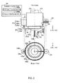
- FIG. 2 is a front view and bottom view for explaining the basic construction of the pre-heating mechanism.
- a guiderail 18 is provided on the fixed side of the cutting drive unit 10 (here, this is the spindle head 10a), and is a ring-shaped metal member that is formed along the circumference and centered around a main axis 10c.
- the rotating body 20 has the same center (main axis 10c) and comprises a ring-shaped metal member 20a having a larger diameter than the guiderail 18, and rollers 20b that are held between the guiderail 10 and metal member 20a and rotatably support the metal member 20a.
- a ring gear 20c is formed around the outer circumference of the rotating body 20, and is used for rotating and moving the laser irradiation unit 22 that will be described later.
- a rotating mechanism such as the rotating body 20 is not limited to comprising configuration of the metal member 20a and rollers 20b, and various methods for moving the laser irradiation unit 22 in the circumferential direction can be used.
- a safety cover 20d for maintaining safety during the cutting process that is ring shaped and hangs down in the vertical direction.
- the laser irradiation unit 22 is fixed particularly to the metal member 20 of the rotating body 20 by way of an arm 32, and by moving in the circumferential direction along the guiderail 18, irradiates a laser on the object 30 to be cut at a predetermined inclination angle ⁇ .
- the electric power required by the laser irradiation unit 22 is received by way of a power line 36 that is wound around a chord reel 34 such that it can extend freely.
- the laser irradiation unit 22 comprises a high-output laser oscillator, and is able to heat an irradiation area that is specified by a 20 mm diameter circle on the surface of the metal object 30 that is to be cut to a temperature of 600°C or greater in less than a second.
- the direction on the horizontal plane of the laser of the laser irradiation unit 22 is fixed in the direction of the main axis 10c (direction of the circle center), and the direction in the vertical direction is set along the inclination angle ⁇ on the tip end side of the cutting tool 10b. Therefore, the irradiation position of the laser is always an equal distance from the main axis 10c when the surface of the object 30 to be cut is assumed to be horizontal, and the irradiation track when the laser irradiation unit 22 is rotated in the circumferential direction along the guiderail 18 is a continuous circle centered around the main axis 10c. The irradiation position of the laser will be described in detail later.
- the laser irradiation drive unit 24 moves the laser irradiation unit 22 to the stopping position on the guiderail 18 that was derived by the irradiation control unit 26 that will be described later. More specifically, the laser irradiation drive unit 24 comprises a pinion 24a, an electric motor 24b that transmits power to the ring gear 20c by way of the pinion 24a, and an encoder 24c that detects the amount of rotation of the rotating shaft of the electric motor 24b. The laser irradiation drive unit 24 accurately moves the laser irradiation unit 22 to the stopping position, which is the target value, according to closed-loop control by the encoder 24c.
- construction is such that the electric motor 24b and encoder 24c do not collide with the laser irradiation unit 22, so the range of rotating movement of the laser irradiation unit 22 is not physically limited.
- the range of rotating movement of the laser irradiation unit 22 is limited to - ⁇ ⁇ angle of rotation ⁇ ⁇ ⁇ .
- the irradiation control unit 26 comprises a semiconductor integrated circuit that includes a central processing unit (CPU), a ROM that stores programs and the like, and a RAM as a work area, and working together with the CAM unit 16, manages and controls the entire cutting device 1.
- the irradiation control unit 26 also functions as a preset cutting position derivation unit 26a, and a stopping position derivation unit 26b.
- the preset cutting position derivation unit 26a based on a NC program, adds the distance moved during a preset predetermined time (hereafter, simply referred to as the movement distance) to the current cutting position (position of the cutting tool 10b) that is known by the CAM unit 16, and derives a preset cutting position that corresponds to the preset cutting site, which is the cutting site of the cutting tool 10b after a predetermined time.
- a preset predetermined time hereafter, simply referred to as the movement distance
- the current cutting position position of the cutting tool 10b
- the NC program mainly uses the position (coordinates) and distance on the X, Y and X axes
- the explanation here uses coordinates and distance that correspond to the preset cutting position after a predetermined time, rather than time.
- this is not limited to a predetermined time, and any unit that corresponds to the predetermined time can be used.
- FIG. 3A to FIG. 3C are drawings for explaining the processing by the preset cutting position derivation unit 26a and the stopping position derivation unit 26b.
- the preset cutting position derivation unit 26a based on a set predetermined time and the relative movement speed of the cutting tool 10b and the object 30 to be cut, finds the product of the predetermined time and relative movement speed beforehand as the movement distance. Then, the preset cutting position derivation unit 26a, by way of the NC program, finds the movement track (movement distance and movement direction) 52 from the current cutting position 50 (coordinates (x0, y0)) in the top view of the cutting device 1 illustrated in FIG. 3A .
- the preset cutting position derivation unit 26a then identifies the preset cutting position, where the distance from the cutting position 50 on the movement track 52 is the movement distance 54 that was found beforehand, and derives the coordinates (x1, y1) that indicate that preset cutting position.
- the coordinate in the Z direction is taken to be the same value and is not considered.
- the preset cutting position derivation unit 26a transmits the current cutting position and the preset cutting position, or the relative distance of the preset cutting position with respect to the current cutting position to the stopping position derivation unit 26b.
- the stopping position derivation unit 26b derives the stopping position of the laser irradiation unit 22 on the guiderail 18 in order to irradiate the laser with the preset cutting position derived by the preset cutting position derivation unit 26a as a target.
- the stopping position derivation unit 26b uses the equations 1 and 2 below to find the distance r to the coordinates (x1, y1) and the angle ⁇ with the coordinates (x0, y0) illustrated in FIG. 3A as a reference.
- the angle ⁇ as illustrated in the bottom view of the cutting device in FIG. 3B , can be used as is as the angle of rotation ⁇ of the laser irradiation unit 22.
- the stopping position derivation unit 26b finds the inclination angle ⁇ using Equation 3 below based on the distance r, the laser irradiation height h from the preset irradiation site, and the laser irradiation horizontal distance d from the main axis 10c.
- ⁇ tan - 1 d - r / h
- the stopping position derivation unit 26b can derive the angle of rotation ⁇ and inclination angle ⁇ of the laser irradiation unit 22.
- the angle of rotation ⁇ of the laser irradiation unit 22 is controlled, and control of the inclination angle ⁇ is omitted.
- the irradiation range of the laser by laser irradiation unit 22 is a large circle having a diameter of 20 mm for example, so even though the preset irradiation position and the actual irradiation position do not exactly match in the radial direction, the preset irradiation position is included in the irradiation position that is fixed in the radial direction.
- the irradiation position of the laser appears in a circle at an equal distance from the main axis 10c.
- the stopping position derivation unit 26b transmits only the rotation angle ⁇ to the laser irradiation drive unit 24.
- the inclination angle ⁇ at which the laser is to be irradiated differs depending on the size and cutting height of the object 30 to be cut, and the protruding dimensions of the cutting tool 10b. Therefore, the user irradiates the laser onto a suitable preset cutting site by manually changing the inclination angle ⁇ of the laser irradiation unit 22 according to the cutting conditions.
- the irradiation angle ⁇ when doing that can be set by taking a plurality of samplings of the estimated distance r and using the average value and standard deviation of that distance r in Equation 3.
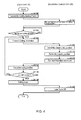
- FIG. 4 is a flowchart that illustrates the overall flow of the cutting method.
- the processing is explained by dividing the processing into that by the CAM unit 16 and that by the irradiation control unit 26.
- the CAM unit 16 references the NC program, acquires the cutting starting position and sends that to the irradiation control unit 26 (S100).
- the irradiation control unit 26 drives the laser irradiation drive unit 24, moves the laser irradiation unit 22 to the cutting starting position, turns the laser ON and starts laser irradiation (S102).
- the CAM unit 16 determines whether or not the waiting time for the laser to preheat the cutting starting position has elapsed (S104), and when the waiting time has not elapsed (S1 04: NO), the judgment of step S104 is repeated.
- the CAM unit 16 references the NC program, acquires all of the information, such as the current position of the cutting tool 10b (current cutting position), that is necessary for deriving the preset cutting position, and sends that information to the irradiation control unit 26 (S106).
- the preset cutting position derivation unit 26a of the irradiation control unit 26 derives the preset cutting position (S108), and the stopping position derivation unit 26b derives the stopping position of the laser irradiation unit 22 on the guiderail 18 with the derived preset cutting position as the target (S110). Then, the laser irradiation drive unit 24, according to a control instruction from the irradiation control unit 26, moves the laser irradiation unit 22 to the derived stopping position (S112).
- the CAM unit 16 controls the cutting drive unit 10 so that cutting is performed at the cutting position indicated in the NC program (S114), and determines whether the NC program indicates that cutting is finished (S116). When the NC program does not indicate cutting is finished (S116: NO), processing is repeated from the information transmission step S1û6. When the NC program indicates that cutting is finished (S116: YES), the CAM unit 16 stops cutting by the cutting drive unit 10 (S118), and the irradiation control unit 26 turns OFF the laser (S120).
- the laser irradiation unit 22 itself moves freely in a range of 360°, so it is possible to perform the cutting process with preheating without being accompanied by the rotation of the object 30 to be cut, which is advantageous when cutting a large member for which rotation of the object 30 to be cut is difficult.
- the laser irradiation unit 22 is able to preheat the preset cutting position that is different than the cutting direction at the same time as cutting, so once cutting begins, it is possible to continuously cut the object 30 to be cut without stopping the cutting process, and thus it is possible to keep the cost and time required for cutting to a minimum.
- the preheating mechanism of this embodiment can be used with an existing cutting device that is for performing milling, so there is no need for special equipment, and it is possible to suppress wear of the cutting tool 10b at low cost.
- the present invention can be used for a cutting device and cutting method that cut an object into a free shape.
Landscapes
- Engineering & Computer Science (AREA)
- Physics & Mathematics (AREA)
- Optics & Photonics (AREA)
- Mechanical Engineering (AREA)
- Plasma & Fusion (AREA)
- Laser Beam Processing (AREA)
- Milling Processes (AREA)
Applications Claiming Priority (1)
| Application Number | Priority Date | Filing Date | Title |
|---|---|---|---|
| JP2011170119A JP5364132B2 (ja) | 2011-08-03 | 2011-08-03 | 切削装置および切削方法 |
Publications (1)
| Publication Number | Publication Date |
|---|---|
| EP2554322A2 true EP2554322A2 (de) | 2013-02-06 |
Family
ID=46516599
Family Applications (1)
| Application Number | Title | Priority Date | Filing Date |
|---|---|---|---|
| EP20120176820 Withdrawn EP2554322A2 (de) | 2011-08-03 | 2012-07-18 | Schneidvorrichtung und -verfahren mit einer Lasereinheit |
Country Status (3)
| Country | Link |
|---|---|
| US (1) | US9248534B2 (de) |
| EP (1) | EP2554322A2 (de) |
| JP (1) | JP5364132B2 (de) |
Cited By (3)
| Publication number | Priority date | Publication date | Assignee | Title |
|---|---|---|---|---|
| CN104786065A (zh) * | 2015-05-06 | 2015-07-22 | 吴江市江南不锈钢器材有限责任公司 | 一种边沿加热式切削装置 |
| CN107855667A (zh) * | 2017-11-29 | 2018-03-30 | 深圳市冰海科技有限公司 | 用于切割柔性线路板的激光切割设备 |
| US10076814B1 (en) | 2017-03-20 | 2018-09-18 | Changwon National University Industry Academy Cooperation Corps | Multiple heat source-type preheating device for machining apparatus |
Families Citing this family (15)
| Publication number | Priority date | Publication date | Assignee | Title |
|---|---|---|---|---|
| JP6056564B2 (ja) * | 2013-03-08 | 2017-01-11 | 株式会社Ihi | セラミックマトリックス複合材の加工方法 |
| TWI508810B (zh) * | 2013-12-13 | 2015-11-21 | Metal Ind Res & Dev Ct | 雷射輔助加工裝置 |
| TWI564104B (zh) * | 2014-06-23 | 2017-01-01 | Soco Machinery Co Ltd | Auxiliary equipment for laser processing |
| JP2017177162A (ja) * | 2016-03-30 | 2017-10-05 | 株式会社Subaru | レーザピーニング加工装置及びレーザピーニング加工方法 |
| KR101726137B1 (ko) | 2016-07-11 | 2017-04-12 | 주식회사 포스코 | 소재절단장치 및, 소재절단시스템 |
| TWI610750B (zh) * | 2016-12-08 | 2018-01-11 | 東台精機股份有限公司 | 複合加工之加工機及其雷射分光裝置 |
| CN109108490A (zh) * | 2018-09-17 | 2019-01-01 | 黎盆兄 | 一种极坐标式精密激光切割设备 |
| KR102294292B1 (ko) * | 2020-04-07 | 2021-08-27 | 창원대학교 산학협력단 | 통전 밀링 장치 |
| CN112519016B (zh) * | 2020-11-25 | 2022-08-23 | 厦门理工学院 | 一种切削装置及其使用方法 |
| CN113894861B (zh) * | 2021-09-28 | 2023-03-28 | 湖南科技大学 | 一种便携式激光加热辅助切削的加工装置 |
| CN113814744A (zh) * | 2021-10-14 | 2021-12-21 | 济南凯之岳机器有限公司 | 一种门窗铝型材钻铣、划线复合加工中心 |
| KR102710948B1 (ko) * | 2022-05-20 | 2024-09-26 | 박수웅 | 공구 냉각 장치 |
| CN115592423B (zh) * | 2022-12-01 | 2023-03-10 | 太原理工大学 | 一种激光辅助钻削的加工装置 |
| CN117020447B (zh) * | 2023-10-10 | 2023-12-22 | 武汉金运激光股份有限公司 | 激光振镜切割自覆膜工作台装置及控制方法 |
| CN120326359B (zh) * | 2025-05-27 | 2025-09-30 | 河北广浩管件有限公司 | 一种金属管件激光切割装置及方法 |
Citations (2)
| Publication number | Priority date | Publication date | Assignee | Title |
|---|---|---|---|---|
| JP2003019615A (ja) | 2001-06-13 | 2003-01-21 | Daimlerchrysler Ag | フライス盤及びフライス切削法 |
| JP2011170119A (ja) | 2010-02-19 | 2011-09-01 | Hitachi Displays Ltd | 液晶表示装置 |
Family Cites Families (9)
| Publication number | Priority date | Publication date | Assignee | Title |
|---|---|---|---|---|
| US4733049A (en) * | 1963-01-11 | 1988-03-22 | Lemelson Jerome H | Machining method and apparatus |
| JPS57156133A (en) * | 1981-03-20 | 1982-09-27 | Hitachi Ltd | Heat cutting device |
| JP3519536B2 (ja) * | 1996-02-29 | 2004-04-19 | 東芝機械株式会社 | クーラント噴出ノズル付き主軸装置およびクーラント供給切削加工方法 |
| FR2750067B1 (fr) * | 1996-06-20 | 1998-07-31 | Snecma | Procede de fraisage assiste par laser |
| JP2001239795A (ja) * | 2000-02-28 | 2001-09-04 | Ando Electric Co Ltd | 打刻方法及びその装置 |
| JP4334109B2 (ja) * | 2000-05-12 | 2009-09-30 | 株式会社牧野フライス製作所 | 機械加工方法及び装置 |
| TW580416B (en) * | 2002-11-28 | 2004-03-21 | Ind Tech Res Inst | Laser-assisted machining process |
| US8053705B2 (en) * | 2005-09-07 | 2011-11-08 | Purdue Research Foundation | Laser assisted machining process with distributed lasers |
| DE102006003682A1 (de) * | 2006-01-24 | 2007-07-26 | Jenoptik Automatisierungstechnik Gmbh | Kombinierte Vorrichtung zur Materialbearbeitung mit einem Fräser und einem Laser |
-
2011
- 2011-08-03 JP JP2011170119A patent/JP5364132B2/ja not_active Expired - Fee Related
-
2012
- 2012-07-18 EP EP20120176820 patent/EP2554322A2/de not_active Withdrawn
- 2012-07-26 US US13/558,950 patent/US9248534B2/en not_active Expired - Fee Related
Patent Citations (2)
| Publication number | Priority date | Publication date | Assignee | Title |
|---|---|---|---|---|
| JP2003019615A (ja) | 2001-06-13 | 2003-01-21 | Daimlerchrysler Ag | フライス盤及びフライス切削法 |
| JP2011170119A (ja) | 2010-02-19 | 2011-09-01 | Hitachi Displays Ltd | 液晶表示装置 |
Cited By (4)
| Publication number | Priority date | Publication date | Assignee | Title |
|---|---|---|---|---|
| CN104786065A (zh) * | 2015-05-06 | 2015-07-22 | 吴江市江南不锈钢器材有限责任公司 | 一种边沿加热式切削装置 |
| US10076814B1 (en) | 2017-03-20 | 2018-09-18 | Changwon National University Industry Academy Cooperation Corps | Multiple heat source-type preheating device for machining apparatus |
| NL2019003B1 (en) * | 2017-03-20 | 2018-09-28 | Nat Univ Changwon Ind Academy Coop Corps | Multiple heat source-type preheating device for machining apparatus |
| CN107855667A (zh) * | 2017-11-29 | 2018-03-30 | 深圳市冰海科技有限公司 | 用于切割柔性线路板的激光切割设备 |
Also Published As
| Publication number | Publication date |
|---|---|
| US20130032015A1 (en) | 2013-02-07 |
| JP2013035069A (ja) | 2013-02-21 |
| JP5364132B2 (ja) | 2013-12-11 |
| US9248534B2 (en) | 2016-02-02 |
Similar Documents
| Publication | Publication Date | Title |
|---|---|---|
| EP2554322A2 (de) | Schneidvorrichtung und -verfahren mit einer Lasereinheit | |
| JP5019001B2 (ja) | 数値制御方法及びその装置 | |
| US20180236576A1 (en) | Combined gear cutting apparatus | |
| US20160089737A1 (en) | Method and apparatus for chamfering and deburring gear cut workpieces | |
| JP2017530016A (ja) | 歯部を加工する方法及び加工用工具並びに工作機械 | |
| KR20140119241A (ko) | 5축 가공기의 레이저 보조 턴-밀 시스템 | |
| WO2013190964A1 (ja) | クラウンギヤの製造装置及び製造方法 | |
| CN102656529A (zh) | 数控装置 | |
| CN103339575B (zh) | 数控装置 | |
| JP2014040001A (ja) | ワーク加工装置とその制御方法 | |
| CN103878635B (zh) | 机床控制系统 | |
| US10702931B2 (en) | Dimple processing method using rotary cutting tool | |
| EP2560786B1 (de) | Verfahren und vorrichtung zum schneiden von öffnungen in flache, konkave oder konvexe oberflächen | |
| WO2013088884A1 (ja) | 工作機械 | |
| JP4503326B2 (ja) | 工具経路データ生成装置及びこれを備えた制御装置 | |
| CA2895007A1 (en) | Method and apparatus for non-spindle multi-axis machining | |
| EP3103576B1 (de) | Bearbeitungsverfahren | |
| JP6744096B2 (ja) | 歯の創成または機械加工のための方法および歯切り盤 | |
| TWI485034B (zh) | 機床控制系統 | |
| CN105014100B (zh) | 一种硬质合金管件压坯的内外圆倒角装置及方法 | |
| US12539555B2 (en) | Friction stir welding device and friction stir welding method | |
| JP2011216050A (ja) | 加工ロボットとその加工制御方法 | |
| JP2016093851A (ja) | 研削装置 | |
| CN211276891U (zh) | 一种基于六轴工业机器人下的冒口切割设备 | |
| JP7143186B2 (ja) | 部品製造方法、加工装置及び部品 |
Legal Events
| Date | Code | Title | Description |
|---|---|---|---|
| PUAI | Public reference made under article 153(3) epc to a published international application that has entered the european phase |
Free format text: ORIGINAL CODE: 0009012 |
|
| AK | Designated contracting states |
Kind code of ref document: A2 Designated state(s): AL AT BE BG CH CY CZ DE DK EE ES FI FR GB GR HR HU IE IS IT LI LT LU LV MC MK MT NL NO PL PT RO RS SE SI SK SM TR |
|
| AX | Request for extension of the european patent |
Extension state: BA ME |
|
| RAP1 | Party data changed (applicant data changed or rights of an application transferred) |
Owner name: FUJI JUKOGYO KABUSHIKI KAISHA |
|
| RAP1 | Party data changed (applicant data changed or rights of an application transferred) |
Owner name: SUBARU CORPORATION |
|
| STAA | Information on the status of an ep patent application or granted ep patent |
Free format text: STATUS: THE APPLICATION HAS BEEN WITHDRAWN |
|
| 18W | Application withdrawn |
Effective date: 20170927 |