EP2554065A1 - Casque protecteur - Google Patents
Casque protecteur Download PDFInfo
- Publication number
- EP2554065A1 EP2554065A1 EP12178795A EP12178795A EP2554065A1 EP 2554065 A1 EP2554065 A1 EP 2554065A1 EP 12178795 A EP12178795 A EP 12178795A EP 12178795 A EP12178795 A EP 12178795A EP 2554065 A1 EP2554065 A1 EP 2554065A1
- Authority
- EP
- European Patent Office
- Prior art keywords
- head
- shock
- headgear
- hat structure
- hat
- Prior art date
- Legal status (The legal status is an assumption and is not a legal conclusion. Google has not performed a legal analysis and makes no representation as to the accuracy of the status listed.)
- Granted
Links
Images

Classifications
-
- A—HUMAN NECESSITIES
- A42—HEADWEAR
- A42B—HATS; HEAD COVERINGS
- A42B1/00—Hats; Caps; Hoods
- A42B1/04—Soft caps; Hoods
- A42B1/08—Soft caps; Hoods with protection against blows
-
- A—HUMAN NECESSITIES
- A42—HEADWEAR
- A42B—HATS; HEAD COVERINGS
- A42B3/00—Helmets; Helmet covers ; Other protective head coverings
- A42B3/003—Helmet covers
Definitions
- the invention relates to a headgear with an at least partially dimensionally stable hat structure and with a protruding at least over a part of a circumference of the hat structure brim, and with a surrounding a head fitting shock absorption shell.
- Such a headgear is from the US 2008/0060117 A1 known.
- the well-known headgear has a protective helmet with a shock-absorbing shell, on the outside of a hat structure is placed with a completely circumferential brim and firmly connected to the outer shell of the protective helmet.
- the object of the invention is to provide a headgear of the type mentioned, which combines an effective head protection function with a pleasing appearance.
- a bottom of the brim is pulled inwards to the Kopfpassform inside and covers a lower edge of the shock absorbing shell.
- the brim covers a lower edge of the shock absorbing shell surrounding the head fitting.
- the head protection function is fully maintained by the shock absorbing shell.
- the fact that the brim is pulled inwards to the head fit, the headgear gives the visual impression of a matching hat.
- either the entire brim may be drawn inwardly to the head fit, or merely a cover forming the underside or a coating forming the underside of the brim.
- Extending the underside of the brim to the head fit means that for an observer, the headgear resting on a wearer's head obliquely from below gives the impression that the underside of the brim or the entire brim from the outside inward to the head contour the carrier runs.
- the headgear according to the invention preferably has a hat structure with a completely circumferential brim.
- the invention also includes a headgear with a hat structure in which the brim protrudes outward only over a part of the circumference of the hat structure (in particular military or police hats with a substantial, forwardly protruding, dimensionally stable protective brim).
- the solution according to the invention is particularly suitable for headgear, which must perform a head protection function on the one hand due to the operation of their wearer and on the other by their appearance a characteristic indication of the performed by the wearer activity.
- Particularly advantageous solution according to the invention in equestrian sports preferably in Western riding or dressage riding, can be used.
- dressage riding the athletes have hitherto been riding as headgear with cylinders that have no head protection function.
- Western riding the athletes ride with Western hats, which also have no head protection function.
- the solution according to the invention can insofar The look of a typical dressage cylinder or a typical Western hat combine with a head protection function.
- the solution according to the invention is also suitable for headgear of uniforms, which should also include a head protection function in addition to the characteristic, matching the uniform appearance.
- the inventive solution consequently protects the wearer's head from injury.
- it is suitably used as a jewelery or characteristic of the wearer's membership of a particular group of persons, be it a particular equestrian group, a professional group or a recreational group.
- the hat structure is at least over a portion of its height at least substantially matched to a Kopfpassform.
- This embodiment is based on the recognition that the aesthetic sensation of a matching to a head of a wearer hat is related to how the contour of the hat structure to the contour of the head of the wearer behaves.
- a matching hat is at least approximately aligned with its hat structure - depending on the viewing angle from the front, from the back or from the side - lateral, front or rear flanks of the head fit of the wearer.
- a front or rear view of the head is selected.
- the hat structure should at least substantially be aligned with the head fitting means that the same alignment should be carried out for the corresponding part of the hat structure, as would be the case with a conventional hat without additional protective function.
- the wording that the hat structure is to be aligned with the head fit over at least a portion of its height means that, starting from the brim to the top of the hat structure, at least one third, preferably half, of the height is a Kopfpassform without additional protective function adapted to match hat.
- the notion of tuning the hat structure to the head fit means that the hat structure over the corresponding portion of its height is designed as a hat structure of a hat without additional head protection function, which is adjusted by its fit size on the head of a corresponding wearer. This means that a lower visible approach of the hat structure must be positioned approximately at the level of alignment of the side edges of the head fitting.
- the hat structure is substantially cylindrical, the hat structure is aligned not only over a small portion of its height, but over its entire visible height substantially with the head fitting.
- Hut With conically or in another way upwardly tapering Hutaccumulated only the lower, visible approach with the Kopfpassform aligned. Upwards then the corresponding conical, hemispherical, pyramidal or otherwise designed taper occurs.
- the shock-absorbing shell has an end ring section in the area of the head fitting with full shock absorption function, a transition ring section with reduced shock absorption function and a head section adjoining the transition section upwards with reduced or full shock absorption function.
- a different shock absorption function is provided.
- the transition ring section is arranged in the region of an externally visible attachment of the hat structure, from which the hat structure continues upward, at least substantially in tune with the head fitting.
- the transition ring portion is formed by a circumferential step between the lower end ring portion and the upper head portion. The Stirnringabites encloses the head of the wearer at the level of a frontal area of the head.
- the transition ring portion additional shock protection means are assigned, which are integrated in the region of the transition ring portion or overlap the transition ring portion outside.
- the impact protection means at least partially compensate for the shock absorption function reduced by the transition ring section itself. Due to the integration in the area of the transition section, the impact protection means are integrated in the shock absorption shell.
- the individual sections of the shock-absorbing shell are preferably formed by energy-absorbing foam material, in particular expanded polystyrene, optionally combined with at least one hard shell on the outer or inner circumference.
- the impact protection means comprise bridge-like effective energy distribution elements, which are arranged such that they transmit impact energy to the end ring portion and / or the head portion of the shock absorbing shell.
- the impact energy striking the transition ring section is at least partially transmitted to the sections above and / or below the shock absorption shell, resulting in a homogenization of the energy absorption.
- the impact protection means have at least one shock-absorbing ring, which is arranged on the outside on the transition ring portion and in particular has the appearance of a hat-shaped cord.
- a shock-absorbing ring may be inserted into an annular step formed by the transition ring section.
- the visual impression of a hat-string hides the additional shock-absorbing function that the corresponding shock-absorbing ring has.
- the shock absorbing shell is constructed in several parts.
- the corresponding parts or sections of the shock-absorbing shell can be detachably or non-detachably connected to one another.
- the end ring section is designed as a ring attached to the outside of the hat structure, which in particular has the outside of the design of a hatband.
- the external placement of the shock-absorbing Stirnringabiteses on the hat structure ensures nestling of the hat structure to the Kopfpassform.
- the externally mounted end ring section assumes the desired head protection function for the head of the wearer of the headgear.
- the advantageous outside design of the ring as a hatband visually hides the Stoßdämpfungs- and protective function of the end ring section.
- the head portion of the shock absorbing shell extends within the hat structure and includes at least over part of the height of the hat structure to an inner contour of the hat structure flush and flat.
- the head portion of the shock absorbing shell can therefore fill the hat structure from the inside at least partially with shock-absorbing material. In addition to a good dimensional stability of the hat structure thereby a further improved protection function for a head of the wearer is achieved.
- the head portion and the end ring portion are provided at their adjacent to the transition ring portion end portions with energy-absorbing thickening.
- these thickening can provide no additional protection.
- the bridge-like effective energy distribution elements are beneficial that transmit the occurring, point-like shock loads on the above and below sections of the shock absorbing shell.
- At least one additional protection module is provided, which is necessary for achieving a predetermined safety helmet standard with higher protection level for the headgear, and which is firmly connected to the shock absorbing shell and / or the hat structure and / or the brim.
- only a basic version can be used, or at least an additional protection module - depending on the requirements of the helmet norm - attached to this basic version.
- the fixed connection between the at least one additional protection module and the shock absorbing shell and / or the hat structure and / or the brim may be provided as a detachable or non-detachable connection.
- the compound can also be advantageously carried out tool-free and non-positive or positive or cohesive.
- the basic version should have at least one provided with a Stirnringabêt and a head portion shock absorbing shell.
- FIG. 1 to 16 Several embodiments of headgear according to the invention having a shock-absorbing head protection function are shown, which each comprise, in addition to a one-part or multi-part shock absorption shell for the head protection function, a hat structure with a peripheral rim.
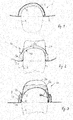
- Fig. 1 shows a particularly simple embodiment of the invention, in which a headgear 1 is provided with a shock absorbing shell 4 for a head K of a human wearer.
- the shock-absorbing shell 4 is covered by a surface of a hat structure 3, which is externally attached to the shock-absorbing shell 4 and the outer contour of the shock-absorbing shell 4 follows.
- a circumferential brim 2 adjoins the hat structure 3 and protrudes outward from the head K.
- the brim 2 is pulled inwardly over a lower edge of the shock absorbing shell 4 to a head fitting of the head K, so that the brim 2 covers the edge of the shock absorbing shell 4.
- the brim 2 is flat and firmly connected to the lower edge of the shock absorbing shell 4, in particular by a cohesive connection.
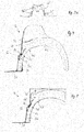
- the headgear 1a has over the embodiment according to Fig. 1 in addition to a shock-absorbing shell 4a and a circumferential rim 2a, a hat structure 3a projecting upwards relative to the shock-absorbing shell 4a.
- the headgear 1a is designed as follows:
- the shock absorbing shell 4a has in a lower region a circumferential end ring section 5a which projects over at the front a front region of the head K of the human wearer of the headgear 1a extends and is pulled around from there around the head K.
- a lower edge of the end ring portion 5a of the shock absorbing shell 4a is covered by a circumferential rim 2a, which is continued in the region of a lower edge of an inner contour of the shock absorbing shell 4a by an unspecified welding band.
- To the Stirnringabites includes a circumferential transition portion 7a, which merges upward in a head portion 6a of the shock absorbing shell 4a.
- the transition section 7a forms an inwardly stepped annular step, through which the shock absorbing shell 4a is made narrower in the transition section 7a.
- the transition section 7a has a reduced shock absorption function relative to the end ring section 5a.
- headgear 1a has a subsequent to the transition portion 7a upwardly head portion 6a, which completely covers the upper portion of the head K.
- the head area 6a as shown Fig. 2 an equally reduced shock absorption function as the transition section 7a.
- For a thickness of the head portion 6a corresponds approximately to a thickness of the transition portion 7a and is reduced relative to the thickness of the end ring portion 5a.
- shock absorption shells based on the Fig. 1 to 16 are described in one or more parts structure, have a material structure with strong energy absorbing properties. Particular preference is given to using a plastic foam material, in particular expanded polystyrene (EPS).
- EPS expanded polystyrene
- the shock-absorbing shells may additionally be provided on the outside and / or inside with coatings or thin-walled support shells.
- a hat structure 3a adjoins the shock-absorbing shell 4a on the outside, which in a front view according to FIG Fig. 2 with its outer contour on the in the area of Sweatband predetermined Kopfpassform the head K is tuned.
- dash-dotted tangents T are aligned approximately with the outer contour of the hat structure 3. These tangents T correspond to the sidewalls of the head fitting.
- the hat structure extends from the transition portion 7a from over more than half the total height of the head covering 1a upwards.
- the hat structure 3a is dimensionally stable made of a suitable textile material, in particular a felt material, constructed and peripherally connected in the region of the transition section 7a fixed to the shock absorbing shell 4a.
- the thicker shaped end ring section 5a is offset radially towards the hat structure 3a relative to a head center axis, resulting in the appearance of a hat band 3a belonging to the hat band.
- the end ring portion 5a is suitably colored on the outside or - in a manner not shown - laminated with a suitable textile material, which is tuned in the manner of a hat band on the hat structure 3a and the rim 2a.
- the brim 2a is preferably made of the same textile material as the hat structure 3a.
- the respective brim 2 to 2k is constructed from a material matched to the associated hat structure 3 to 3k.
- the corresponding material may be single or multi-layered and has a sufficient dimensional stability in order to ensure a stable Nachau jointragen the brim 2 to 2k.
- the brim 2 to 2k of textile material or leather.
- the shock absorbing shell 4b is constructed in several parts. Opposite the headgear 1a after Fig. 2 the headgear 1b has some significant differences. To the one is the shock absorbing shell 4b on the inside, ie in the region of the head contour in addition to the shock absorption properties with a dimensionally stable, thin support shell 8 is provided. At a lower edge region of the support shell 8, the outwardly projecting brim 2b connects, which is executed circumferentially. In the area of the head fit, the lower edge region of the support shell 8 is provided with a sweatband 10, which adjoins the brim 2b, which is drawn inwardly up to the head fit.
- the shock absorbing shell 4b shows in the embodiment Fig. 3 a head portion 6b, which is externally placed on the support shell 8 and fixedly connected thereto.
- the head portion 6b fills a dimensionally stable hat structure 3b inside partially, which is pulled down to the brim 2b.
- the hat structure 3b can according to Fig. 3a be carried out integrally with the brim 2b.
- a commercially available headgear in particular in the form of a Western hat or a cylinder, with a hat structure 3b 'and an integrally formed brim 2b' may be provided, the outer and inner side Stoßdämpfungsschalen 4b 'as shown Fig. 3a assigned.
- the headgear is after Fig. 3a according to the embodiment according to Fig. 3 so as to supplement the disclosure to the description of Fig. 3 is referenced.
- the end ring section 5b of the shock absorbing shell 4b is arranged separately from the head section 6b and designed as a separate ring, which encloses on the outside a lower region of the hat structure 3b.
- the end ring portion 5b sits flush on the brim 2b and is fixedly connected inwardly with the hat structure 3b and the support shell 8.
- the end ring portion 5b is made of energy-absorbing material analogous to the material of the head portion 6b.
- the head portion 6b is pulled down to the level of the end ring portion 5b and is made very narrow in this area, as shown in the Fig. 3 is recognizable.
- the end ring portion 5b may be laminated on the outside with a textile material 9, to analogous to Fig. 2 for the Stirnringabêt 5b to convey the visual impression of a hatband.
- the head section 6b follows the inner contour of the hat structure 3b over part of its height, the head section 6b forms thickened regions which assume an additional shock-absorbing function.
- the end ring portion 5b is also made sufficiently thick and designed to absorb energy. Thereby, the head portion 6b and the head ring portion 5b for the head K form a sufficient shock absorbing function.
- the shock absorption function is reduced, since here the outer contour of the headgear 1b must be kept narrower to the vote of the hat structure 3b on the Kopfpassform to enable.
- a one-piece shock-absorbing shell 4c is provided, which is concealed in its lower edge region by a brim 2c, which circulates around the headgear 1c.
- One Sweatband 10 connects on the inside to the shock-absorbing shell 4c.
- the shock-absorbing shell 4c is also provided with an end ring section 5c, a narrower transition ring section 7c and a head section 6c adjoining the transition section 7c at the top.
- the hat structure 3c is set in such a way that, with its lateral outer contour, it is aligned substantially with the head fitting.
- the hat structure 3c is additionally supported on the inside by a thickening 11 of the head section 6c.
- the end ring portion 5c has a thickening 12, which is provided at an upper edge of the end ring portion 5.
- the Stirnringabites 5c goes over by means of a ring stage in the transition ring section 7c and then in the head section 6c.
- the transition ring section 7c energy distribution elements 13 are assigned, which are integrated as dimensionally stable bridges in the energy absorbing material of the shock absorbing shell 4c and an approximately occurring impact energy in the derive thicker, downwardly and upwardly adjoining sections of the shock-absorbing shell 4c.
- an energy-absorbing ring 14 can be inserted on the outside in the annular step shoulder formed by the transition ring section 7c, which consists of a suitable plastic material, in particular silicone. This ring 14 can cause an additional shock-absorbing function at the level of the transition ring portion 7c.
- the headgear 1d after Fig. 5 corresponds to the headgear 1c according to their functional structure Fig. 4 , The main difference is in the embodiment according to Fig. 5 in that the hat structure 3d is designed in the manner of a cylinder.
- the headgear 1d can therefore be used as a cylinder for dressage riding, wherein the cylinder assumes the additional head protection function already described above.
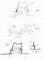
- Fig. 6 to 10 various types of power distribution elements 15, 15 ', 15 ", 15"', 16 are provided for corresponding headgear 1e, 1f, 1g having the same function as the power distribution elements 13 of FIGS 4 and 5 .
- All power distribution elements based on the Fig. 6 to 10 have a bridge function to distribute impact energy that might impact the corresponding transition ring portion 7e, 7f on the adjacent portions with higher shock absorption function, namely, the upper head portion 6e, 6f and the lower end ring portion 5e, 5f, 5g.
- the various embodiments according to the Fig. 6 to 10 differ in that in the embodiments according to the Fig.
- the impact energy is already derived on the outside before the impact of the impact on the transition ring portion 7e.
- the corresponding bridge-shaped energy distribution elements 15, 15 ' are placed outside on the hat structure.
- the power distribution elements 15 are designed as bow-shaped bridges, which are arranged distributed in multiple versions over the circumference of the hat structure.
- Each bridge body 15 has large-volume support surfaces in the region of the head section 6e and the end ring section 5e.
- the energy distribution element 15 ' is designed as a lattice-like profile ring, which is supported convexly curved at the level of the transition ring portion 7e and is firmly connected to the hat structure.
- the headgear 1f has two schematically illustrated variants of energy distribution elements 15 "and 15"'that are integrated into the shock absorption shell 4f. Only one of the two variants will be used in a shock-absorbing shell 4f. In the shock absorption shell 4f after Fig. 9 Thus, two alternatives are integrated, of which only one will actually be used.
- Each of the two energy distribution elements 15 ", 15" is in each case annular, so that the distribution of the impact energy at the level of the transition ring section 7f is ensured circumferentially over the entire circumference of the head.
- the power distribution element 15 '' is stepped and follows flush the outer contour of the hat structure
- the energy distribution element 15 '' has a convex cross section and follows approximately parallel to an inner contour of the shock absorbing shell 4f.
- annular power distribution element 16 is externally placed on the shock absorbing shell and follows flush the outer contour of the hat structure and the shock absorbing shell in the region of the end ring portion 5g and the stepped shoulder of the transition ring portion 7g.
- the headgear 1h and 1i are provided with additional ventilation channels 17 in the region of their shock-absorbing shells.
- the respective hat structure 3h, 3i is provided with ventilation openings 18 to discharge the air which has passed through the shock absorption shell into the interior of the hat structure 3h, 3i to the outside.
- the structure of the headgear 1 h and 1i corresponds to at least one of the embodiments already described above.
- the headgear 1i has an outer, thin-walled support ring 16, which performs the function of an energy distribution ring 16 Fig. 10 has.
- the support ring 16 is dimensionally stable and impact resistant and extends over the outer contour of the end ring portion 5i, the transition ring portion 7i and a portion of the height of the head portion 6i.
- the head assembly 3i starts at the level of the transition ring portion 7i.
- the stepped shoulder in the region of the transition ring section 7i is additionally filled on the outside by a damping ring 14, which is optically can be designed in the manner of a hat cord.
- the shock absorbing shell of the headgear 1i in the embodiment is after Fig. 12 on the inside additionally provided with a padding 19.
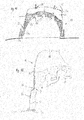
- a modular construction of a headgear 1k is shown.
- the headgear 1k forms according to the illustration Fig. 13 a hat with a wide, circumferential brim 2k, a hat band 5k and a hat structure 3k.
- the hat is provided with a shock absorbing shell, which is formed by a hat band forming the end ring portion 5k and a head portion 6k.
- the hat structure 3k will, as the basis of Fig. 15 can be seen, mounted in a simple manner from above on the shock absorbing shell and connected to this.
- the brim 2k is detachably arranged to the shock absorbing shell and can be set or disconnected from this by suitable connection means.
- the end ring section 5k may be laminated with a textile material in the manner of a hatband ( Fig. 14 ).
- both brims and hat structures are provided in different designs, which can be exchanged modularly depending on the purpose.
- corresponding brim modules and / or Hutantemodule be releasably connected to corresponding shock-absorbing shells, the Stirnringabête and head portions connectable.
- Corresponding connection means in all embodiments according to Fig. 13 to 16 are in particular operated without tools.
- suitable connecting means Velcro straps or strips, push buttons or the like are provided.
- the shock absorbing shell can be supplemented by an occipital guard 20.
- a chin strap 21 may additionally be provided. Both the occiput guard 20 and the chin strap 21 form additional protection modules that can be attached to the existing shock absorbing shell and firmly connected to this.
- FIGS. 15 and 16 It can be seen how the occiput guard 20 can be inserted by means of a corresponding web profiling in a corresponding groove profiling of a lower edge of the shock absorbing shell in the region of the end ring portion 5k.
- the connection of the occiput guard 20 with the underside of the end ring portion 5k can be cohesive, non-positive or positive or as a combination of these compounds.
- the protection module in the form of the occiput guard 20 is releasably attached to the underside of the shock absorbing shell.
- the shock absorbing shell can be supplemented with an additional protective function or not. It is also envisaged to detachably connect the protective module in the form of the chinstrap 21 to the shock-absorbing shell in order to be able to obtain a higher protection level here as well, if necessary.
Applications Claiming Priority (1)
| Application Number | Priority Date | Filing Date | Title |
|---|---|---|---|
| DE102011080464A DE102011080464A1 (de) | 2011-08-04 | 2011-08-04 | Kopfbedeckung mit einem zumindest abschnittsweise formstabilen Hutaufbau |
Publications (2)
| Publication Number | Publication Date |
|---|---|
| EP2554065A1 true EP2554065A1 (fr) | 2013-02-06 |
| EP2554065B1 EP2554065B1 (fr) | 2015-02-25 |
Family
ID=46982382
Family Applications (1)
| Application Number | Title | Priority Date | Filing Date |
|---|---|---|---|
| EP12178795.6A Not-in-force EP2554065B1 (fr) | 2011-08-04 | 2012-08-01 | Casque protecteur |
Country Status (3)
| Country | Link |
|---|---|
| US (1) | US20130031701A1 (fr) |
| EP (1) | EP2554065B1 (fr) |
| DE (1) | DE102011080464A1 (fr) |
Families Citing this family (5)
| Publication number | Priority date | Publication date | Assignee | Title |
|---|---|---|---|---|
| USD735417S1 (en) | 2013-08-16 | 2015-07-28 | Karen M. Stauning | Helmet cover |
| US10390582B2 (en) | 2014-12-05 | 2019-08-27 | Two Guys And A Hat Inc. | Protective headgear |
| US10004290B2 (en) * | 2014-12-05 | 2018-06-26 | Two Guys And A Hat Inc. | Protective headgear |
| USD804734S1 (en) | 2015-10-21 | 2017-12-05 | Two Guys And A Hat Inc. | Protective headgear |
| CA3038060C (fr) * | 2016-09-23 | 2020-12-22 | Johnnie CLARK | Chapeau de rafraichissement |
Citations (4)
| Publication number | Priority date | Publication date | Assignee | Title |
|---|---|---|---|---|
| US3103015A (en) * | 1962-02-01 | 1963-09-10 | Plastino Mario | Head-protecting head gear |
| US3286275A (en) * | 1964-12-30 | 1966-11-22 | American Safety Equip | Safety helmet |
| WO2004016122A1 (fr) * | 2002-08-16 | 2004-02-26 | Di Giovanni, Frances, Grace | Accessoire vestimentaire de protection |
| US20080060117A1 (en) | 2006-08-25 | 2008-03-13 | Troxel, Llc | Combination Hat And Helmet |
Family Cites Families (9)
| Publication number | Priority date | Publication date | Assignee | Title |
|---|---|---|---|---|
| US2893014A (en) * | 1956-06-05 | 1959-07-07 | Theron W Mabry | Fibreglass cap |
| US5226180A (en) * | 1991-12-02 | 1993-07-13 | Leach Robert E | Protective cap for golfers |
| US5519895A (en) * | 1993-04-28 | 1996-05-28 | Barnes, Jr.; Montie M. | Cap for sports helmet |
| US5437064A (en) * | 1994-02-22 | 1995-08-01 | Hamaguchi; Melvin M. | Protective cap apparatus |
| AUPR060600A0 (en) * | 2000-10-06 | 2000-11-02 | Blair, Mary Lynne | Protective sports hat insert device |
| GB0116738D0 (en) * | 2001-07-09 | 2001-08-29 | Phillips Helmets Ltd | Protective headgear and protective armour and a method of modifying protective headgear and protective armour |
| US20080010721A1 (en) * | 2006-07-13 | 2008-01-17 | Campbell Douglas A | Removable, reusable, washable liner for use with various types of head gear |
| US20110219852A1 (en) * | 2010-03-10 | 2011-09-15 | Kasten Stephen P | Impact monitoring apparatus |
| US8613114B1 (en) * | 2012-07-25 | 2013-12-24 | 2nd Skull, LLC | Head guard |
-
2011
- 2011-08-04 DE DE102011080464A patent/DE102011080464A1/de not_active Ceased
-
2012
- 2012-08-01 EP EP12178795.6A patent/EP2554065B1/fr not_active Not-in-force
- 2012-08-03 US US13/566,106 patent/US20130031701A1/en not_active Abandoned
Patent Citations (4)
| Publication number | Priority date | Publication date | Assignee | Title |
|---|---|---|---|---|
| US3103015A (en) * | 1962-02-01 | 1963-09-10 | Plastino Mario | Head-protecting head gear |
| US3286275A (en) * | 1964-12-30 | 1966-11-22 | American Safety Equip | Safety helmet |
| WO2004016122A1 (fr) * | 2002-08-16 | 2004-02-26 | Di Giovanni, Frances, Grace | Accessoire vestimentaire de protection |
| US20080060117A1 (en) | 2006-08-25 | 2008-03-13 | Troxel, Llc | Combination Hat And Helmet |
Also Published As
| Publication number | Publication date |
|---|---|
| EP2554065B1 (fr) | 2015-02-25 |
| US20130031701A1 (en) | 2013-02-07 |
| DE102011080464A1 (de) | 2013-02-07 |
Similar Documents
| Publication | Publication Date | Title |
|---|---|---|
| DE102011122796B4 (de) | Schutzhelm, insbesondere für Fahrradfahrer | |
| EP2592956B1 (fr) | Équipement intérieur pour un casque de protection destiné notamment à des ouvriers forestiers | |
| EP2554065B1 (fr) | Casque protecteur | |
| DE212016000139U1 (de) | Schutzhelm | |
| EP2498636B1 (fr) | Casque de protection destiné notamment à des ouvriers forestiers | |
| DE602005005786T2 (de) | Halbstarrer schutzhelm | |
| DE60016719T2 (de) | Innenausstattung für schützende kopfbedeckung | |
| EP3177163B1 (fr) | Casque de protection | |
| EP1860964B1 (fr) | Bandeau serre-tete | |
| WO2013104549A1 (fr) | Casque de protection et partie de support pour celui-ci | |
| DE202014011251U1 (de) | Kopfbekleidungsartikel | |
| DE102008028709B4 (de) | Schutzhelm | |
| EP1136007B1 (fr) | Casquette protectrice | |
| DE2952406C2 (de) | Schutzhelm, insbesondere Integralhelm | |
| DE10057814B4 (de) | Vorrichtung zur Halterung eines Helms | |
| DE2061087A1 (de) | Schutzhelm mit einstellbarem Kopfband | |
| DE202013100777U1 (de) | Kapuzensystem | |
| EP2298094A2 (fr) | Système de protection pour colonne vertébrale, veste munie d'un tel système et procédé de fabrication d'un tel système | |
| EP1332688B1 (fr) | Casque | |
| EP3827683B1 (fr) | Système de protection de la tête | |
| EP2877051B1 (fr) | Casque de protection pour avalanche | |
| DE102005006083B4 (de) | Sturzhelm | |
| DE102016119236A1 (de) | Schutzvorrichtung, insbesondere Helm, mit stoßabsorbierendem, homogen belüftendem Aufbau | |
| DE202013011222U1 (de) | Nackenschutz und damit ausgestatteter Schutzhelm | |
| DE102009038763B4 (de) | Schutzhelm mit einer festen Helmkalotte |
Legal Events
| Date | Code | Title | Description |
|---|---|---|---|
| PUAI | Public reference made under article 153(3) epc to a published international application that has entered the european phase |
Free format text: ORIGINAL CODE: 0009012 |
|
| AK | Designated contracting states |
Kind code of ref document: A1 Designated state(s): AL AT BE BG CH CY CZ DE DK EE ES FI FR GB GR HR HU IE IS IT LI LT LU LV MC MK MT NL NO PL PT RO RS SE SI SK SM TR |
|
| AX | Request for extension of the european patent |
Extension state: BA ME |
|
| 17P | Request for examination filed |
Effective date: 20130805 |
|
| RBV | Designated contracting states (corrected) |
Designated state(s): AL AT BE BG CH CY CZ DE DK EE ES FI FR GB GR HR HU IE IS IT LI LT LU LV MC MK MT NL NO PL PT RO RS SE SI SK SM TR |
|
| 17Q | First examination report despatched |
Effective date: 20131023 |
|
| GRAP | Despatch of communication of intention to grant a patent |
Free format text: ORIGINAL CODE: EPIDOSNIGR1 |
|
| INTG | Intention to grant announced |
Effective date: 20140910 |
|
| GRAS | Grant fee paid |
Free format text: ORIGINAL CODE: EPIDOSNIGR3 |
|
| GRAA | (expected) grant |
Free format text: ORIGINAL CODE: 0009210 |
|
| AK | Designated contracting states |
Kind code of ref document: B1 Designated state(s): AL AT BE BG CH CY CZ DE DK EE ES FI FR GB GR HR HU IE IS IT LI LT LU LV MC MK MT NL NO PL PT RO RS SE SI SK SM TR |
|
| REG | Reference to a national code |
Ref country code: GB Ref legal event code: FG4D Free format text: NOT ENGLISH |
|
| REG | Reference to a national code |
Ref country code: CH Ref legal event code: EP |
|
| REG | Reference to a national code |
Ref country code: IE Ref legal event code: FG4D Free format text: LANGUAGE OF EP DOCUMENT: GERMAN |
|
| REG | Reference to a national code |
Ref country code: DE Ref legal event code: R096 Ref document number: 502012002332 Country of ref document: DE Effective date: 20150409 |
|
| REG | Reference to a national code |
Ref country code: AT Ref legal event code: REF Ref document number: 711153 Country of ref document: AT Kind code of ref document: T Effective date: 20150415 |
|
| REG | Reference to a national code |
Ref country code: NL Ref legal event code: VDEP Effective date: 20150225 |
|
| REG | Reference to a national code |
Ref country code: LT Ref legal event code: MG4D |
|
| PG25 | Lapsed in a contracting state [announced via postgrant information from national office to epo] |
Ref country code: NO Free format text: LAPSE BECAUSE OF FAILURE TO SUBMIT A TRANSLATION OF THE DESCRIPTION OR TO PAY THE FEE WITHIN THE PRESCRIBED TIME-LIMIT Effective date: 20150525 Ref country code: HR Free format text: LAPSE BECAUSE OF FAILURE TO SUBMIT A TRANSLATION OF THE DESCRIPTION OR TO PAY THE FEE WITHIN THE PRESCRIBED TIME-LIMIT Effective date: 20150225 Ref country code: SE Free format text: LAPSE BECAUSE OF FAILURE TO SUBMIT A TRANSLATION OF THE DESCRIPTION OR TO PAY THE FEE WITHIN THE PRESCRIBED TIME-LIMIT Effective date: 20150225 Ref country code: LT Free format text: LAPSE BECAUSE OF FAILURE TO SUBMIT A TRANSLATION OF THE DESCRIPTION OR TO PAY THE FEE WITHIN THE PRESCRIBED TIME-LIMIT Effective date: 20150225 Ref country code: FI Free format text: LAPSE BECAUSE OF FAILURE TO SUBMIT A TRANSLATION OF THE DESCRIPTION OR TO PAY THE FEE WITHIN THE PRESCRIBED TIME-LIMIT Effective date: 20150225 Ref country code: ES Free format text: LAPSE BECAUSE OF FAILURE TO SUBMIT A TRANSLATION OF THE DESCRIPTION OR TO PAY THE FEE WITHIN THE PRESCRIBED TIME-LIMIT Effective date: 20150225 |
|
| PG25 | Lapsed in a contracting state [announced via postgrant information from national office to epo] |
Ref country code: RS Free format text: LAPSE BECAUSE OF FAILURE TO SUBMIT A TRANSLATION OF THE DESCRIPTION OR TO PAY THE FEE WITHIN THE PRESCRIBED TIME-LIMIT Effective date: 20150225 Ref country code: GR Free format text: LAPSE BECAUSE OF FAILURE TO SUBMIT A TRANSLATION OF THE DESCRIPTION OR TO PAY THE FEE WITHIN THE PRESCRIBED TIME-LIMIT Effective date: 20150526 Ref country code: IS Free format text: LAPSE BECAUSE OF FAILURE TO SUBMIT A TRANSLATION OF THE DESCRIPTION OR TO PAY THE FEE WITHIN THE PRESCRIBED TIME-LIMIT Effective date: 20150625 Ref country code: LV Free format text: LAPSE BECAUSE OF FAILURE TO SUBMIT A TRANSLATION OF THE DESCRIPTION OR TO PAY THE FEE WITHIN THE PRESCRIBED TIME-LIMIT Effective date: 20150225 |
|
| PG25 | Lapsed in a contracting state [announced via postgrant information from national office to epo] |
Ref country code: NL Free format text: LAPSE BECAUSE OF FAILURE TO SUBMIT A TRANSLATION OF THE DESCRIPTION OR TO PAY THE FEE WITHIN THE PRESCRIBED TIME-LIMIT Effective date: 20150225 |
|
| PG25 | Lapsed in a contracting state [announced via postgrant information from national office to epo] |
Ref country code: EE Free format text: LAPSE BECAUSE OF FAILURE TO SUBMIT A TRANSLATION OF THE DESCRIPTION OR TO PAY THE FEE WITHIN THE PRESCRIBED TIME-LIMIT Effective date: 20150225 Ref country code: DK Free format text: LAPSE BECAUSE OF FAILURE TO SUBMIT A TRANSLATION OF THE DESCRIPTION OR TO PAY THE FEE WITHIN THE PRESCRIBED TIME-LIMIT Effective date: 20150225 Ref country code: CZ Free format text: LAPSE BECAUSE OF FAILURE TO SUBMIT A TRANSLATION OF THE DESCRIPTION OR TO PAY THE FEE WITHIN THE PRESCRIBED TIME-LIMIT Effective date: 20150225 Ref country code: RO Free format text: LAPSE BECAUSE OF FAILURE TO SUBMIT A TRANSLATION OF THE DESCRIPTION OR TO PAY THE FEE WITHIN THE PRESCRIBED TIME-LIMIT Effective date: 20150225 Ref country code: SK Free format text: LAPSE BECAUSE OF FAILURE TO SUBMIT A TRANSLATION OF THE DESCRIPTION OR TO PAY THE FEE WITHIN THE PRESCRIBED TIME-LIMIT Effective date: 20150225 |
|
| REG | Reference to a national code |
Ref country code: DE Ref legal event code: R097 Ref document number: 502012002332 Country of ref document: DE |
|
| PG25 | Lapsed in a contracting state [announced via postgrant information from national office to epo] |
Ref country code: PL Free format text: LAPSE BECAUSE OF FAILURE TO SUBMIT A TRANSLATION OF THE DESCRIPTION OR TO PAY THE FEE WITHIN THE PRESCRIBED TIME-LIMIT Effective date: 20150225 |
|
| PG25 | Lapsed in a contracting state [announced via postgrant information from national office to epo] |
Ref country code: IT Free format text: LAPSE BECAUSE OF FAILURE TO SUBMIT A TRANSLATION OF THE DESCRIPTION OR TO PAY THE FEE WITHIN THE PRESCRIBED TIME-LIMIT Effective date: 20150225 |
|
| PLBE | No opposition filed within time limit |
Free format text: ORIGINAL CODE: 0009261 |
|
| STAA | Information on the status of an ep patent application or granted ep patent |
Free format text: STATUS: NO OPPOSITION FILED WITHIN TIME LIMIT |
|
| 26N | No opposition filed |
Effective date: 20151126 |
|
| PG25 | Lapsed in a contracting state [announced via postgrant information from national office to epo] |
Ref country code: SI Free format text: LAPSE BECAUSE OF FAILURE TO SUBMIT A TRANSLATION OF THE DESCRIPTION OR TO PAY THE FEE WITHIN THE PRESCRIBED TIME-LIMIT Effective date: 20150225 |
|
| PG25 | Lapsed in a contracting state [announced via postgrant information from national office to epo] |
Ref country code: MC Free format text: LAPSE BECAUSE OF FAILURE TO SUBMIT A TRANSLATION OF THE DESCRIPTION OR TO PAY THE FEE WITHIN THE PRESCRIBED TIME-LIMIT Effective date: 20150225 Ref country code: LU Free format text: LAPSE BECAUSE OF FAILURE TO SUBMIT A TRANSLATION OF THE DESCRIPTION OR TO PAY THE FEE WITHIN THE PRESCRIBED TIME-LIMIT Effective date: 20150801 |
|
| REG | Reference to a national code |
Ref country code: CH Ref legal event code: PL |
|
| PG25 | Lapsed in a contracting state [announced via postgrant information from national office to epo] |
Ref country code: CH Free format text: LAPSE BECAUSE OF NON-PAYMENT OF DUE FEES Effective date: 20150831 Ref country code: LI Free format text: LAPSE BECAUSE OF NON-PAYMENT OF DUE FEES Effective date: 20150831 |
|
| REG | Reference to a national code |
Ref country code: IE Ref legal event code: MM4A |
|
| PG25 | Lapsed in a contracting state [announced via postgrant information from national office to epo] |
Ref country code: IE Free format text: LAPSE BECAUSE OF NON-PAYMENT OF DUE FEES Effective date: 20150801 |
|
| REG | Reference to a national code |
Ref country code: FR Ref legal event code: PLFP Year of fee payment: 5 |
|
| PG25 | Lapsed in a contracting state [announced via postgrant information from national office to epo] |
Ref country code: MT Free format text: LAPSE BECAUSE OF FAILURE TO SUBMIT A TRANSLATION OF THE DESCRIPTION OR TO PAY THE FEE WITHIN THE PRESCRIBED TIME-LIMIT Effective date: 20150225 |
|
| GBPC | Gb: european patent ceased through non-payment of renewal fee |
Effective date: 20160801 |
|
| PG25 | Lapsed in a contracting state [announced via postgrant information from national office to epo] |
Ref country code: BG Free format text: LAPSE BECAUSE OF FAILURE TO SUBMIT A TRANSLATION OF THE DESCRIPTION OR TO PAY THE FEE WITHIN THE PRESCRIBED TIME-LIMIT Effective date: 20150225 Ref country code: SM Free format text: LAPSE BECAUSE OF FAILURE TO SUBMIT A TRANSLATION OF THE DESCRIPTION OR TO PAY THE FEE WITHIN THE PRESCRIBED TIME-LIMIT Effective date: 20150225 Ref country code: HU Free format text: LAPSE BECAUSE OF FAILURE TO SUBMIT A TRANSLATION OF THE DESCRIPTION OR TO PAY THE FEE WITHIN THE PRESCRIBED TIME-LIMIT; INVALID AB INITIO Effective date: 20120801 |
|
| PG25 | Lapsed in a contracting state [announced via postgrant information from national office to epo] |
Ref country code: CY Free format text: LAPSE BECAUSE OF FAILURE TO SUBMIT A TRANSLATION OF THE DESCRIPTION OR TO PAY THE FEE WITHIN THE PRESCRIBED TIME-LIMIT Effective date: 20150225 |
|
| PG25 | Lapsed in a contracting state [announced via postgrant information from national office to epo] |
Ref country code: GB Free format text: LAPSE BECAUSE OF NON-PAYMENT OF DUE FEES Effective date: 20160801 Ref country code: BE Free format text: LAPSE BECAUSE OF NON-PAYMENT OF DUE FEES Effective date: 20150831 |
|
| REG | Reference to a national code |
Ref country code: FR Ref legal event code: PLFP Year of fee payment: 6 |
|
| PG25 | Lapsed in a contracting state [announced via postgrant information from national office to epo] |
Ref country code: TR Free format text: LAPSE BECAUSE OF FAILURE TO SUBMIT A TRANSLATION OF THE DESCRIPTION OR TO PAY THE FEE WITHIN THE PRESCRIBED TIME-LIMIT Effective date: 20150225 |
|
| PG25 | Lapsed in a contracting state [announced via postgrant information from national office to epo] |
Ref country code: MK Free format text: LAPSE BECAUSE OF FAILURE TO SUBMIT A TRANSLATION OF THE DESCRIPTION OR TO PAY THE FEE WITHIN THE PRESCRIBED TIME-LIMIT Effective date: 20150225 Ref country code: PT Free format text: LAPSE BECAUSE OF FAILURE TO SUBMIT A TRANSLATION OF THE DESCRIPTION OR TO PAY THE FEE WITHIN THE PRESCRIBED TIME-LIMIT Effective date: 20150225 |
|
| REG | Reference to a national code |
Ref country code: FR Ref legal event code: PLFP Year of fee payment: 7 |
|
| REG | Reference to a national code |
Ref country code: AT Ref legal event code: MM01 Ref document number: 711153 Country of ref document: AT Kind code of ref document: T Effective date: 20170801 |
|
| PG25 | Lapsed in a contracting state [announced via postgrant information from national office to epo] |
Ref country code: AL Free format text: LAPSE BECAUSE OF FAILURE TO SUBMIT A TRANSLATION OF THE DESCRIPTION OR TO PAY THE FEE WITHIN THE PRESCRIBED TIME-LIMIT Effective date: 20150225 |
|
| PG25 | Lapsed in a contracting state [announced via postgrant information from national office to epo] |
Ref country code: AT Free format text: LAPSE BECAUSE OF NON-PAYMENT OF DUE FEES Effective date: 20170801 |
|
| PGFP | Annual fee paid to national office [announced via postgrant information from national office to epo] |
Ref country code: FR Payment date: 20210823 Year of fee payment: 10 |
|
| PGFP | Annual fee paid to national office [announced via postgrant information from national office to epo] |
Ref country code: DE Payment date: 20210819 Year of fee payment: 10 |
|
| REG | Reference to a national code |
Ref country code: DE Ref legal event code: R119 Ref document number: 502012002332 Country of ref document: DE |
|
| PG25 | Lapsed in a contracting state [announced via postgrant information from national office to epo] |
Ref country code: FR Free format text: LAPSE BECAUSE OF NON-PAYMENT OF DUE FEES Effective date: 20220831 Ref country code: DE Free format text: LAPSE BECAUSE OF NON-PAYMENT OF DUE FEES Effective date: 20230301 |