EP2552783B1 - High speed poucher and corresponding method - Google Patents
High speed poucher and corresponding method Download PDFInfo
- Publication number
- EP2552783B1 EP2552783B1 EP11726176.8A EP11726176A EP2552783B1 EP 2552783 B1 EP2552783 B1 EP 2552783B1 EP 11726176 A EP11726176 A EP 11726176A EP 2552783 B1 EP2552783 B1 EP 2552783B1
- Authority
- EP
- European Patent Office
- Prior art keywords
- drum
- pouch
- procession
- pouches
- tube
- Prior art date
- Legal status (The legal status is an assumption and is not a legal conclusion. Google has not performed a legal analysis and makes no representation as to the accuracy of the status listed.)
- Active
Links
Images


Classifications
-
- B—PERFORMING OPERATIONS; TRANSPORTING
- B65—CONVEYING; PACKING; STORING; HANDLING THIN OR FILAMENTARY MATERIAL
- B65B—MACHINES, APPARATUS OR DEVICES FOR, OR METHODS OF, PACKAGING ARTICLES OR MATERIALS; UNPACKING
- B65B1/00—Packaging fluent solid material, e.g. powders, granular or loose fibrous material, loose masses of small articles, in individual containers or receptacles, e.g. bags, sacks, boxes, cartons, cans, or jars
- B65B1/02—Machines characterised by the incorporation of means for making the containers or receptacles
-
- B—PERFORMING OPERATIONS; TRANSPORTING
- B65—CONVEYING; PACKING; STORING; HANDLING THIN OR FILAMENTARY MATERIAL
- B65B—MACHINES, APPARATUS OR DEVICES FOR, OR METHODS OF, PACKAGING ARTICLES OR MATERIALS; UNPACKING
- B65B1/00—Packaging fluent solid material, e.g. powders, granular or loose fibrous material, loose masses of small articles, in individual containers or receptacles, e.g. bags, sacks, boxes, cartons, cans, or jars
- B65B1/30—Devices or methods for controlling or determining the quantity or quality or the material fed or filled
- B65B1/48—Checking volume of filled material
-
- B—PERFORMING OPERATIONS; TRANSPORTING
- B65—CONVEYING; PACKING; STORING; HANDLING THIN OR FILAMENTARY MATERIAL
- B65B—MACHINES, APPARATUS OR DEVICES FOR, OR METHODS OF, PACKAGING ARTICLES OR MATERIALS; UNPACKING
- B65B29/00—Packaging of materials presenting special problems
-
- B—PERFORMING OPERATIONS; TRANSPORTING
- B65—CONVEYING; PACKING; STORING; HANDLING THIN OR FILAMENTARY MATERIAL
- B65B—MACHINES, APPARATUS OR DEVICES FOR, OR METHODS OF, PACKAGING ARTICLES OR MATERIALS; UNPACKING
- B65B43/00—Forming, feeding, opening or setting-up containers or receptacles in association with packaging
- B65B43/42—Feeding or positioning bags, boxes, or cartons in the distended, opened, or set-up state; Feeding preformed rigid containers, e.g. tins, capsules, glass tubes, glasses, to the packaging position; Locating containers or receptacles at the filling position; Supporting containers or receptacles during the filling operation
- B65B43/50—Feeding or positioning bags, boxes, or cartons in the distended, opened, or set-up state; Feeding preformed rigid containers, e.g. tins, capsules, glass tubes, glasses, to the packaging position; Locating containers or receptacles at the filling position; Supporting containers or receptacles during the filling operation using rotary tables or turrets
-
- B—PERFORMING OPERATIONS; TRANSPORTING
- B65—CONVEYING; PACKING; STORING; HANDLING THIN OR FILAMENTARY MATERIAL
- B65B—MACHINES, APPARATUS OR DEVICES FOR, OR METHODS OF, PACKAGING ARTICLES OR MATERIALS; UNPACKING
- B65B43/00—Forming, feeding, opening or setting-up containers or receptacles in association with packaging
- B65B43/42—Feeding or positioning bags, boxes, or cartons in the distended, opened, or set-up state; Feeding preformed rigid containers, e.g. tins, capsules, glass tubes, glasses, to the packaging position; Locating containers or receptacles at the filling position; Supporting containers or receptacles during the filling operation
- B65B43/54—Means for supporting containers or receptacles during the filling operation
- B65B43/60—Means for supporting containers or receptacles during the filling operation rotatable
-
- B—PERFORMING OPERATIONS; TRANSPORTING
- B65—CONVEYING; PACKING; STORING; HANDLING THIN OR FILAMENTARY MATERIAL
- B65B—MACHINES, APPARATUS OR DEVICES FOR, OR METHODS OF, PACKAGING ARTICLES OR MATERIALS; UNPACKING
- B65B51/00—Devices for, or methods of, sealing or securing package folds or closures; Devices for gathering or twisting wrappers, or necks of bags
- B65B51/10—Applying or generating heat or pressure or combinations thereof
- B65B51/26—Devices specially adapted for producing transverse or longitudinal seams in webs or tubes
-
- B—PERFORMING OPERATIONS; TRANSPORTING
- B65—CONVEYING; PACKING; STORING; HANDLING THIN OR FILAMENTARY MATERIAL
- B65B—MACHINES, APPARATUS OR DEVICES FOR, OR METHODS OF, PACKAGING ARTICLES OR MATERIALS; UNPACKING
- B65B57/00—Automatic control, checking, warning, or safety devices
- B65B57/02—Automatic control, checking, warning, or safety devices responsive to absence, presence, abnormal feed, or misplacement of binding or wrapping material, containers, or packages
-
- B—PERFORMING OPERATIONS; TRANSPORTING
- B65—CONVEYING; PACKING; STORING; HANDLING THIN OR FILAMENTARY MATERIAL
- B65B—MACHINES, APPARATUS OR DEVICES FOR, OR METHODS OF, PACKAGING ARTICLES OR MATERIALS; UNPACKING
- B65B57/00—Automatic control, checking, warning, or safety devices
- B65B57/10—Automatic control, checking, warning, or safety devices responsive to absence, presence, abnormal feed, or misplacement of articles or materials to be packaged
- B65B57/14—Automatic control, checking, warning, or safety devices responsive to absence, presence, abnormal feed, or misplacement of articles or materials to be packaged and operating to control, or stop, the feed of articles or material to be packaged
-
- B—PERFORMING OPERATIONS; TRANSPORTING
- B65—CONVEYING; PACKING; STORING; HANDLING THIN OR FILAMENTARY MATERIAL
- B65B—MACHINES, APPARATUS OR DEVICES FOR, OR METHODS OF, PACKAGING ARTICLES OR MATERIALS; UNPACKING
- B65B61/00—Auxiliary devices, not otherwise provided for, for operating on sheets, blanks, webs, binding material, containers or packages
- B65B61/04—Auxiliary devices, not otherwise provided for, for operating on sheets, blanks, webs, binding material, containers or packages for severing webs, or for separating joined packages
- B65B61/06—Auxiliary devices, not otherwise provided for, for operating on sheets, blanks, webs, binding material, containers or packages for severing webs, or for separating joined packages by cutting
-
- B—PERFORMING OPERATIONS; TRANSPORTING
- B65—CONVEYING; PACKING; STORING; HANDLING THIN OR FILAMENTARY MATERIAL
- B65B—MACHINES, APPARATUS OR DEVICES FOR, OR METHODS OF, PACKAGING ARTICLES OR MATERIALS; UNPACKING
- B65B9/00—Enclosing successive articles, or quantities of material, e.g. liquids or semiliquids, in flat, folded, or tubular webs of flexible sheet material; Subdividing filled flexible tubes to form packages
- B65B9/10—Enclosing successive articles, or quantities of material, in preformed tubular webs, or in webs formed into tubes around filling nozzles, e.g. extruded tubular webs
Definitions
- the present application relates to methods and apparatus for producing small sealed pouches material such as smokeless tobacco, and more particularly to such methods and apparatus that operate at extremely high speeds to produce pouches at rates of multiple thousands of units per hour.
- Snus is a smokeless tobacco product sold in pouch form for adult smokers.
- the pouches contain tobacco and flavorants such as spearmint, peppermint or spice to name a few.
- the pouches are designed for placement in the mouth of the user, and the subsequent release of flavorant and tobacco liquids into the oral cavity.
- Individual pouches normally are sold in quantities of six or more pouches per retail package.
- the production of snus filled pouches has been undertaken with pouching machines such as a MediSeal machine of MediSeal GmbH of Schloss-Holte, Germany and those which are offered by Merzmaschines Machinen GmbH of Lich, Germany. These machines generally operate by folding a ribbon of base web into a vertically directed tubular form, sealing along the tubular form to form a longitudinal seam as the tubular form is drawn downwardly and transversely sealing at a location along the tube to form a first (lower) transverse seam.
- the web usually comprises paper.
- the web preferably comprises polypropylene or other suitable material to facilitate thermal sealing of the seams.
- Tobacco is fed into the partially formed pouch and then a second (upper) transverse seal is formed to complete the pouch structure, which is then severed from the remainder of the tubular form.
- This operation is repeated for each pouch, one pouch after another, and all of the aforementioned steps are executed within close proximity of each other, such that the desired, orthogonal orientation of the longitudinal seam relative to the transverse seams is assured.
- the pouches are relatively small and high speed production requires very special components that cooperate with one another in a highly beneficial manner.
- US 3,236,021 discloses methods and apparatus for the forming, filling and sealing of packages made from flexible packaging material in which the packages are formed from individual tubes of flexible packaging material, each of a length corresponding to the desired package length.
- the present invention is directed to machinery and the methods capable of high speed pouch production, with a capacity to maintain the desired orientation of the seams and enhanced consistency in pouch length and volume and other attributes.
- one of the objects of the preferred embodiments is to provide a high speed poucher that functions to produce small sealed pouches of material such as tobacco in a highly beneficial and efficient manner.
- Another object of the present invention is a poucher that produces multiple thousands of such pouches per hour.
- Another object of the preferred embodiments is to provide a method of producing small sealed pouches of material such as tobacco and, optionally, flavors in a highly beneficial and efficient manner.
- Still another object the of preferred embodiments is to provide a high speed poucher and method for producing small, sealed pouches of granular, powder or solid materials in a highly beneficial and efficient manner.
- an endless supply of paper substrate is conveyed in a downstream direction, and at the same time, a separate endless supply of flavor film or strip also is conveyed in a downstream direction.
- the flavor strip is cut into pieces of unit length, and ultimately, each piece of flavor strip is glued in place on top of the traveling paper substrate with equal spacing between the strips on the substrate. Glue also is applied along one edge on top of the paper.
- the paper substrate with glue on one edge thereof and with the flavor strip pieces in place thereon is then conveyed through a garniture where the paper substrate is formed into an endless hollow tube with the opposite edges thereof glued together thereby forming an endless longitudinal seam.
- a structure within the formed tube may be used to support and maintain the tube shape.
- Such structure may comprise an interior brush or interior roller bar engaging the interior surface of the tube for the purpose of maintaining the structural integrity of the tube and enhancing the sealing of the longitudinal seam.
- outside vacuum may be applied to form the tube and seal the longitudinal seam.
- the tubes may be cut to a length for the production of multiple pouches, and then cut, graded and aligned downstream on a series of fluted transfer the drums.
- the longitudinal seam may be located at (oriented toward) the bottom of a receiving flute or drum cavity or 180° opposite that location. This orientation ensures that subsequent crimping of the ends of the tube occurs with the longitudinal seam midway between the side edges of each formed pouch or other relative position, if desired.
- a series of drums including appropriately fluted and beveled drums position the individual tubes in a vertical direction at the end of their path of travel from one fluted drum to the next.
- the hollow tubes are placed on the outside flutes of a processing wheel having a vertical axis of rotation.
- Each tube is placed on one of the flutes of the wheel with its longitudinal seam at the bottom of the receiving flute or 180° opposite that location.
- a pair of crimping rollers directly below the processing wheel functions to crimp and thereby to sealingly close the lower end of each tube.
- Each crimping roller preferably has a vertical axis of rotation and both axes are positioned on a radius of the processing wheel.
- rotation of the processing wheel conveys the tube to a filling station where tobacco or other content is fed into the tubes.
- a second pair of crimping rollers is located above the processing wheel for crimping closed the top of each tube.
- the vertical axis of each of the second crimping rollers is positioned along a radius of the processing wheel which ensures that the top crimp is parallel to the lower crimp with the longitudinal seam midway between the sides of each pouch being formed.
- the pouches then are removed from the processing wheel, inspected for quality control and packaged for transport.
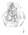
- a high speed poucher machine 10 which has the capacity to produce 1,300 to 1,700 individual pouches per minute, each pouch preferably containing a predetermined portion of tobacco and a suitable flavorant, if desired and optionally a dissolvable flavor film or strip, such as that which is described in US Published Patent Application Nos. US 2007/0261707A1 and US 2007/0012328A1 .
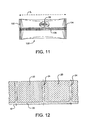
- the product being formed in the preferred embodiments is a pouch 100 having crimped end portions that are sealed along transverse seams 102, 104 that preferably are parallel to one another.
- a longitudinal seam 106 extends between the crimped ends, and preferably parallel to the sides of the pouch, in an orthogonal relation to the transverse seams 102 and 104.
- the longitudinal seam 106 is located midway between the sides of the pouch, although its relative position could be selected to be closer to one side than the other.
- Each pouch 100 has a predetermined length "L".
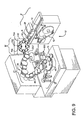
- a high speed poucher machine 10, 10' capable of producing individual pouches 100 of a predetermined, unit length L.
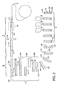
- Each machine 10, 10' comprises a first section A, A' which repetitively forms open-ended, multi-unit length tubular elements 101 from a continuous ribbon of base web 12 with each tubular element 101 having a longitudinal seam 106 at a given orientation and having a length preferably of a multiple of the aforementioned, predetermined unit length L; a transfer section or mechanism B,B' which transfers the output of the section A, A' onto a first drum 202 of a drum section C,C', with orientation of the aforementioned longitudinal seam 106 in a radial relation with respect to the first drum, which orientation is maintained along subsequent drums of the drum section C, C'; (the drum section C, C' also cuts, grades and aligns pieces of the aforementioned multi-unit length tubular elements 101 into a procession of individual pouch length tubes 101' of the predetermined length L);
- an endless supply of web 12 is conveyed in a downstream direction at a velocity V1.
- Web usually comprises paper, and preferably may comprise polypropylene or other suitable material to facilitate thermal sealing of the seams.
- a continuous ribbon (or endless supply) of flavor film or strip) 14 is conveyed in a downstream direction at a slightly lower velocity V2, which velocity V2 is determined by the size (diameter) of a metering roller 17 that is located upstream of a cork roller 16 along the path of the ribbon of flavor film 14.
- Glue is applied to the flavor film by applicator 18.
- the flavor film is fed into a nip between a knife-drum 19 and the cork drum 16, where the film 14 is cut into pieces 20 of unit length and retained on the cork drum.
- the cork drum has a surface velocity V3, which is equal to the velocity V1, and the differential between V2 and V3 produces a predetermined spacing 24 between the cut pieces 20 of flavor film 14 on the cork drum.
- the slower velocity V2 of the endless supply of flavor film and the slightly higher surface velocity of the cork drum uniquely produces the desired spacing.
- the spaced apart flavor strip pieces 20 then are glued or otherwise set in place on the traveling paper substrate.
- glue or other adhesive 25 also is applied along one edge 27 of the paper by an applicator 26 or other suitable device.
- vacuum 21 may be applied to a vacuum chamber 23 inside the cork drum 16 to assist in holding the cut piece 20 of flavor film to the surface of the cork drum 16.
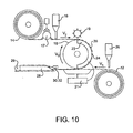
- the vacuum 21 also may be supplied to the underside of the paper substrate 12 to assist in holding the pieces 20 of flavor film 14 to the top of the paper, as shown in Figure 10 .
- the paper substrate with glue along one edge 27 and with the flavor film pieces 20 in place then is conveyed through a garniture 28 where the paper substrate is formed into an continuous hollow tube 29 and the opposite edge portions of the paper are glued together, forming a longitudinal seam 106 as shown in Figure 2 .
- the longitudinal seam 106 becomes the longitudinal seam 106 which appears in the finished pouch 100.
- An interior brush 30 may be used in forming and supporting the hollow paper tube which may be omitted when a flavor film 14 is included within the tube 29.
- an interior roller bar 32 may be used for that purpose.
- Outside vacuum may be applied to facilitate tube formation and, in some instances, outside vacuum may be used without any interior supportive structure, particularly when a continuous flavor film 14 is combined with the web 12, which is less prone to collapse than a tubular structure comprising only the web (without any flavor film).
- the formation of the continuous paper tube 29 can be executed using the endless, porous belt drive of a KDF-2 of Hauni Körber, Hamburg Germany or similar apparatus to draw the web 12 through the garniture 28.
- the garniture 28 has folding surfaces and glue applicators similar to those used in garnitures used in tobacco rod makers in cigarette makers and may include ports to apply vacuum to the outside of the web being folded in the garniture to assure retention of shape.
- the tube is cut by cutter 34 into tubular elements 101 having lengths equal to multiples of the length of the individual pouch 100 (i.e., two-up, four-up, six-up of length L or greater). Cutting the tube into tubular elements 101 having lengths equal to the length of the individual pouch 100 (i.e. a one-up length) might avoid the need for section C, C' and allow for section B, B' to feed directly into section D, D' of the machine 10, but a one-up element is difficult to transfer and will often tumble. It is operationally, therefore, advantageous to create at the cutter 34 tubular elements 101 of a multi-unit length and to transfer the tubular elements 101 from section A, A' of the machine 10, 10' via its section B, B'.
- the tubular elements 101 of multiple unit lengths are moved along a series of fluted drums 36 in section C, C' in a downstream direction utilizing pocketed or fluted wheel-to-wheel, vacuum transfer technology.
- the drum or wheel sections Preferably, there are included among the drum or wheel sections those that cut, grade and align pieces of tubular elements 101 such that at the end of the section C, C' of the machine 10, 10' there is established a procession of one-up, open ended tubular elements 101'.
- a two-up tubular element 101 may be transferred onto the first drum 202 of section C, C' and subsequently directed through drum sections that cut (sever the workpiece into multiple pieces), grade (circumferentially displace the severed pieces with respect to one another) and align (converge the displaced pieces into a row in line with one another) as represented at the designations 204, 206 and 208, respectively. It is to be understood that a four-up tubular element would require additional repetitions of these operations, an eight-up yet more and so forth.
- Section C, C' of the embodiments of the machine 10, 10' may further include beveled drums or wheels 46 which turn the procession of one-up tubular elements 101' from a generally horizontal disposition to a generally vertical disposition conducive to the filling and crimping operations to be executed as the procession of one-up tubular elements 101' are moved through the section D,D'.
- the transfer and placement of the multi-unit length tubular elements 101 onto the first drum 202 of section C, C' is executed so that the longitudinal seam 106 is ultimately aligned radially outwardly with respect to the radius of the drum 202 at the respective receiving flute or cavity (or 180° opposite that orientation, i.e., radially inwardly).
- This radial relationship is maintained throughout the drum-to-drum transfers in the section C, C' and ensures that subsequent crimping and sealing of the ends of the one-up tubular elements 101' in section D, D' occurs with the transverse seams 102 and 104 in the desired orthogonal relation with respect to the longitudinal seam 106 thereof and that the longitudinal seam 106 is positioned consistently, preferably midway between the side edges of the formed pouch 100.
- the radial relation may include a selected angle, instead of the preferred 0° and 180° radial relation discussed above.
- the series of drums 36 includes a beveled drum 46 that positions the individual tubes 101' in a vertical orientation at the end of their path of travel from one drum to the next.
- the one-up tubular elements 101' then are directed via the last drum of section C, C' onto the outside of a continuously rotating processing wheel 48 which may have a vertical axis of rotation in section D, D' of the machine 10, 10', which placement includes maintenance of the aforementioned radial relationship of the longitudinal seam 106.
- a pair of crimping rollers 50, 52 directly below the processing wheel function to crimp and thereby sealingly close the lower end of each one-up tubular element 101' and form the lower, transverse seam 102.
- Each crimping roller preferably has a vertical axis of rotation and both axes are positioned along a radius of the wheel.
- a filling station 300 where tobacco 56 or other content is fed into the tubular elements 101'.
- a hopper 58 and vibratory pan feeder 60 function to perform the tobacco or other content filling operation.
- Content feeding and filling apparatuses also are described in US Patents Nos. 5,221,247 and 5,542,901 .
- a filling method and apparatus is disclosed in US Patent No. 5,875,824 .
- a second pair of crimping rollers 70, 72 spaced above the processing wheel 48 functions to crimp and seal the upper end portion or top of each one-up tubular element 101' to form the upper transverse seam 104.
- the vertical axes of both crimping rollers preferably are positioned (mutually aligned) along a radius of the processing wheel to ensure thereby that the top seam 104 is parallel to the lower seam 102 and the longitudinal seam 106 is midway between the sides.
- the filling station 300 includes an inspection and feed control system 400 comprising a sensor 402 at a location along the path of the procession of one-up tubular elements 101' intermediate of where delivery of content (for example, tobacco) is completed and the top crimping rollers 70, 72, a processor 404, a feed-rate controller 406 and a rejection station 408.
- the sensor 402 is adapted to generate a signal indicative of the level of content in each (or a representative number) of filled tubular elements 101' as they progress toward the top crimping rollers 70, 72.
- the feed rate controller 406 is operative to adjust the vibration and/or the depth of tobacco 56 on the vibrating pan 60, either to elevate or to diminish delivery rate of the content responsive to signals generated by the sensor 402.
- the processor 404 is programmed to process and communicate signals among the operative elements of the system (the sensor 402, the feed rate controller 406 and the rejection station 408). This system 400 is operative such that should the level or volume of pouch content (or filled volume) trend away from a predetermined value (away from a product specification loaded into the processor 406), the processor 404 will adjust operation of the feed rate controller 406 responsively and counteractively to the detected trend, so that filling operations may be precisely maintained in real time and on-line.
- the processor may be programmed to operate the rejection station 408 to remove the out-of-specification product from the processing wheel 48.
- the rejection station 408 may include a controllable air jet which directs a pulse of air radially outwardly with respect to the wheel 48 having sufficient force to overcome the vacuum retention at the flute of the wheel 48 holding the rejectable product.
- Mechanical pins or other expedients may be used in lieu or addition thereof in the rejection station 408.
- the rejection station 408 is located upstream of (before) the top crimping rollers 70, 72 such that the rejected product is and remains open-ended to facilitate both the inspection and recovery of content.
- Recovered content can be returned to the hopper 58, thereby avoiding waste and minimizing processing steps in the recovery of content.
- the rejection station 408 may be located downstream of the top crimping rollers 70, 72 such that the rejection of product is executed with fully closed (completed) pouches 100 and content is not allowed to scatter and impact cleanliness of the filling operations. This approach may be preferred if the content is particularly fine or otherwise prone to scatter.
- the inspection and control system preferably further comprises one or more final inspection stations or sensors 409 located along the pathway of the procession of completed pouches 100 while they continue movement on the processing wheel 48 or subsequent wheels (drums), so that inspection can be executed in an orderly and complete manner.
- Such arrangement presents the longitudinal and transverse seams 106, 104 and 102 to the sensor 409 for such inspection, repetitively and in an orderly, consistent manner to facilitate such inspection.
- the completed pouches 100 are transferred to another drum having another inspection station or sensor 409', where the other side of the completed pouches 100 is presented for inspection.
- the pouches 100 are removed from the processing wheel 48 or a subsequent wheel, optionally inspected further for quality control and packaged.
- Each finished pouch preferably contains a predetermined portion of tobacco and optionally a flavor film.
- the machine 10, 10' is capable of making and filling pouches with other forms of content, not just tobacco, such as granular, powder or solid content, for example.
- Figures 1 and 2 illustrate one of the preferred embodiments of the present invention comprising the high speed poucher 10.
- the poucher 10 has four sections comprising the tube formation section A, the tube transfer section B, the tube cutting, grading and aligning section C and the tube crimping, filling and closing section D.
- the tube formation section A includes an endless supply of paper substrate 12 conveyed in a downstream direction by suitable conveyor means (not shown) at a representative velocity V1.
- an endless supply of flavor film or strip 14 also is conveyed in a downstream direction by a driven cork faced drum 16 at a slightly lower velocity V2.
- the flavor strip is cut into unit length pieces 20 at the nip of the strip 14 and the drum 16 by any common cutting element, such as a reciprocating knife blade or knife drum 19, for example.
- V2 and V3 produce a predetermined spacing 24 between the cut pieces 20 of the flavor strip on the cork drum.
- the slower velocity V2 of the endless supply of flavor strip 14 and the slightly higher surface velocity of the cork drum uniquely produces the desired spacing 24.
- the spaced apart cut pieces 20 then are glued in place on the traveling substrate 12 such as shown in Figure 12 .
- Glue 25 from applicator 26 also is applied along one edge 27 of the paper substrate. Vacuum 21 assists in holding the flavor film strips 20 to the cork drum and the paper substrate 12, as explained above.
- the paper substrate 12 with glue 25 along edge 27 and with the flavor strips 20 in place then is conveyed through a garniture 28 where the paper substrate 12 is formed into an endless hollow tube 29 and where the opposite edge portions of the paper are glued together, forming the longitudinal seam 106.
- the garniture 28 for tube formation may be utilized including one that includes the interior brush 30 as shown in Figures 3 and 4 , or the interior roller bar 32 as shown in Figures 3A or 4A .
- the paper substrate 12 with the spaced apart flavor film 20 thereon is drawn through the garniture 28 by an air permeable endless belt and rolled into a tubular form.
- Any suitable garniture structure may be utilized for that purpose, as described above.
- the interior brush 30 functions to hold and maintain the tube formed by the garniture and to assist in a tight longitudinal seam 106.
- the interior roller bar 32 produces the same results of maintaining the tubular shape of the paper substrate.
- the rollers have a curved radius equal to that of the formed hollow tube 29 ensuring optimal tube formation.
- a vacuum plenum may be utilized in the garniture to assist in formation of the tube 29.
- the brush and/or rollers at the garniture counteract the tendency of the paper to collapse. Such expediencies are not needed when a flavor film is included, because the web and film structure has lesser tendency to collapse. Applying vacuum at one or more locations along the garniture is effective in facilitating folding action with the web and film structure, because of air impermeable nature of the flavor film.
- a cutter 34 is positioned to cut the endless tube 29 into predetermined lengths 101.
- each cut tube 101 may be of a length sufficient to form two pouches 100.
- Each length of the so-called 2-up tube then is transferred at the transfer section B to a series of mostly fluted drums 36 which cut, grade and align the tube 101 into one-up lengths 101' each for the formation of a single pouch 100.
- the 2-up tube 101 is cut in half to produce two individual lengths 101', and then the lengths 101' are graded and aligned as described previously.
- the transfer of the cut tube 101 to the first drum 202 of the series of drums 36 in the embodiment of Figure 1 preferably is executed with a catcher drum 202 which repetitively receives the output of the cutter 34 in a flute 604 as each flute 604 arrives at the 12 o'clock rotational position of the drum 202
- the catcher drum arrangement includes a stop 606 operative at each flute 604 to stop and register each tubular element 101 consistently along each of the flutes 604.
- one or more, vacuum assisted rotating rollers 602 help move the tubular elements into flutes 604.
- vacuum ports 623 at spaced locations along the periphery of the roller or rollers 602 facilitate movement of the tubular element 101 into place.
- one or more vacuum ports 609 apply vacuum to retain the element 101 in the respective flute 604 with the desired orientation of the seam 106.
- the catcher drum may include a circumferential arcuate rail or canard 608 at the 12 o'clock position of the drum 202 to help guide the tubular element 101 into place.
- the drum 202 includes a fixed internal vacuum plenum 610, which extends circumferentially from the 12 o'clock position to the point of transfer to the next drum 295. Vacuum from vacuum source 612 is communicated through the vacuum ports 609 as the fluted rotational body 611 of drum 202 rotates.
- Consistent placement of the tubular lengths 101 onto the first drum 202 is important in that the longitudinal seam 106 must be located at the bottom of one of the tube receiving cavities on the outside of the drum 202, alternatively, in a 180° opposite relation to that location. This is necessary in order to ensure that crimping of the ends of the individual tube lengths occurs with the longitudinal seam at a preferred location midway between the side edges of the formed pouch, as shown in Figure 11 .
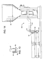
- transfer of the multi-unit length tubular elements 101 at section B' is executed using a Hauni Transfer Spider 92 such as a Hauni Protos SE 80 "Spider" (or other model) having vacuum operated gripper bars 702 at the ends of armitures 704.
- the arms 704 are all rotatable via rotation of the Spider's disk 706 and each arm 704 is rotatable relative to the disk 706.
- the Spider is positioned downstream of section A' such that it picks up a tubular element 101 at the cutter 34 (as shown in Fig. 8 as designation X).
- the gripper 702 When adjacent the cutter 34, the gripper 702 through application of a vacuum grips the tubular element 101 at its 3 o'clock position and moves to a delivery location adjacent the 3 o'clock position of the receiving drum 202' (which is at designation Y in Fig. 8 ), and then returns to the position x along an elliptical path.
- vacuum is interrupted and the tubular element 101 is released and picked up by application of vacuum by the drum 202'.
- the tubular element 101 is oriented with the seam 106 initially at an angle to the radius of the drum 202' instead of the desired alignment with the radius of the drum 202'.
- the drum 202' of this embodiment includes a circumferentially wide flute 40, which includes a "backstop" surface 41, and a roll-bar 42 which rolls the delivered tubular element 101 back against the backstop 41 such that the desired radical relation is achieved such as shown at designation Z in Fig. 8 .
- Section B' is illustrated in canted relation to sections A' and C', it would be aligned with section A' such that the axis of rotation of the disk 706, of Spider is at a 90° relation to the axis of rotation of the drum 202'.
- Hauni Protos SE 80 "Spider” is particularly beneficial in the production of pouches having an interior flavor film.
- the multi length tube 101 of Figure 8 shows the longitudinal seam at the top of the tube and when transferred to the first drum 202' by vacuum transfer the position of the longitudinal seam is as shown.
- the roller bar 42 engages the tubes 101 to rotate the tubes within the receiving cavities 40 on the outside of the drum 202'.
- the cavities are designed so as to allow rotation of the tubes 101 to an ultimate position where the longitudinal seam is positioned on a radius of the drum 202' as shown.
- the multiple length tubes 101 are cut, graded and aligned by the fluted drums at that section as described above.
- a single tube 101' for production of a single pouch 100 is conveyed by beveled drum 46 which positions each individual tube 101' in a vertical orientation at the end of the path of travel from one fluted drum to the next at station C'.
- each individual hollow tube 101' is placed on the outside (periphery) of the rotating processing wheel 48 having a vertical axis of rotation.
- the pair of crimping rollers 50, 52 at a fixed location directly below the processing wheel 48 function to crimp and thereby sealingly close the lower end of each tube.
- Each crimping roller 50, 52 preferably has a vertical axis of rotation and both axes are positioned along a radius of the processing wheel 48.
- the processing wheel 48 After the closing of the lower end of the tube 101', continued rotation of the processing wheel 48 conveys the tubes to filling station where tobacco 56 or other content is fed into the tubes.
- the hopper 58 and vibratory pan feeder 60 at the filling station function to perform the tobacco filling operation.
- the feed rate may be controlled by varying the vibration and the depth of tobacco 56 on the vibrating pan 60.
- the processing wheel 48 has a series of funnel like pockets 62 around the perimeter of the wheel.
- the top of each pocket 62 has the shape of a truncated circular sector, and the bottom of each pocket is a round hole 64.
- the hole in each pocket preferably is located directly above the open end of a tube 101'.
- the walls of the pockets 62 are oriented to facilitate flow of the tobacco 56 into the tubes 101'.
- the bottom of the pocket 62 may include an extension 66 that fits inside the open end of the tube 101'.
- the inner and outer walls of the pocket may extend to form a trough to capture the discharge of the vibratory pan feeder 60.
- the walls 68 between adjacent pockets 62 form a sharp edge such that all of the tobacco or other content that falls into the pockets flows through the pockets into the tubes 101'.
- the discharge may be vertical or may be inclined.
- each pocket 62 moves through the "waterfall” of tobacco 56 or other content being delivered by vibratory pan feeder 60, the tobacco is funneled through the pocket into the tube 101' positioned below the bottom opening 64, 66 of each pocket. Since the tobacco flow is consistent in both flow and discharge shape, and each pocket 62 of the processing wheel 48 is identical in size and shape, and the rate of rotation of the wheel is constant, the amount of tobacco captured by each pocket 62 is consistent. As a result, the amount of tobacco 56 or other content loaded into each tube 101' is consistent.
- the sizing of the various components and the tobacco flow rate is such that all of the tobacco is delivered from the pockets to the tubes 101' in less than a full revolution of the processing wheel 48, and the remainder of the revolution may be used for crimp closing the tubes, inspection as noted above and rejection of pouches out of specification, other quality control measures, unloading the pouches 100 and loading empty tubes 101' onto the processing wheel 48.
- the second pair of crimping rollers 70, 72 are at a fixed location and spaced above the processing wheel 48 for crimp-closing and sealing the top of each tube 101' to form the upper, second transverse seam 104. Similar to the first pair of crimping rollers 50, 52, preferably the vertical axes of each of the second crimping rollers is positioned along the radius of the processing wheel 48 to thereby ensure that the upper transverse seam 104 is parallel to the lower transverse seam 102 and that the longitudinal seam 106 is midway between the sides of the finished pouch 100 and that the upper transverse seam is in the desired orthogonal relation to the longitudinal seam 106.
- the crimping rollers may be heated to enhance sealing along the transverse seams of the tubes 101'. Also, adhesive may be applied to the inside open edges of the tube to enhance closure, if desired. These features may also be used to form the lower crimp as well.
- the formed pouches 100 then may be removed from the processing wheel 48, inspected for quality control, as explained above, and packaged for transport.
- Each finished pouch 100 preferably contains tobacco 56 and optionally a dissolvable flavor film 20.
- Figures 6 and 7 diagrammatically illustrate another embodiment of the present invention where the endless flavor film 14 is disposed along a continuous paper substrate 12 without the flavor strip being cut into individual pieces, such as shown in Figure 10 .
- adhesive is applied to the top of the paper substrate by an applicator 80, and the endless flavor film 14 then is glued in place on the paper substrate with vacuum being applied via chamber 82 as the substrate and flavor strip move in a downstream direction.
- the ribbon of paper 12 has a width greater than that of the ribbon of flavor film 14, and the paper and flavor film ribbons mutually are arranged so that the longitudinal edge 84 of the paper substrate 12 is without flavor film to facilitate formation of the longitudinal seam 106 as the paper strip is rolled into tubular form by the garniture 28 as described above.
- the garniture is used to form the tube, and any known garniture or other folding apparatus may be used for that purpose such as those described above or others well known in the art.
- any known garniture or other folding apparatus may be used for that purpose such as those described above or others well known in the art.
- the remaining downstream operations to final pouch formation may be similar to those described above in connection with the poucher 10, 10' of Figures 1 and 9 .
- the crimping and material filling section preferably comprises a series of drums or wheels to facilitate execution of its functionalities. It is possible to conduct its crimping filling, closing and, optionally, inspection functionalities at locations along a linear fashion instead of along rotating drums or wheels. Likewise for the section C, C'.
- the flavor film 14 whether in pieces 20 or continuous also functions as an interior liner which reduces the tendency of the tobacco 56 or other content to discolor (stain) the paper 12 by reducing the opportunity for moisture from the tobacco or its additives, if any, to reach the paper prior to use.
- the flavor film 14 also allows the moisture content and other properties of the tobacco to be maintained in its original (fresh) condition until actual use.
Landscapes
- Engineering & Computer Science (AREA)
- Mechanical Engineering (AREA)
- Quality & Reliability (AREA)
- Containers And Plastic Fillers For Packaging (AREA)
- Making Paper Articles (AREA)
- Manufacture Of Tobacco Products (AREA)
- Bag Frames (AREA)
- Supplying Of Containers To The Packaging Station (AREA)
Priority Applications (1)
| Application Number | Priority Date | Filing Date | Title |
|---|---|---|---|
| PL11726176T PL2552783T3 (pl) | 2010-03-26 | 2011-03-28 | Saszetkarka o dużej szybkości i odpowiedni sposób |
Applications Claiming Priority (2)
| Application Number | Priority Date | Filing Date | Title |
|---|---|---|---|
| US31792610P | 2010-03-26 | 2010-03-26 | |
| PCT/IB2011/001149 WO2011117751A2 (en) | 2010-03-26 | 2011-03-28 | High speed poucher |
Publications (2)
| Publication Number | Publication Date |
|---|---|
| EP2552783A2 EP2552783A2 (en) | 2013-02-06 |
| EP2552783B1 true EP2552783B1 (en) | 2014-09-24 |
Family
ID=44581813
Family Applications (1)
| Application Number | Title | Priority Date | Filing Date |
|---|---|---|---|
| EP11726176.8A Active EP2552783B1 (en) | 2010-03-26 | 2011-03-28 | High speed poucher and corresponding method |
Country Status (14)
| Country | Link |
|---|---|
| US (7) | US9623988B2 (pl) |
| EP (1) | EP2552783B1 (pl) |
| JP (1) | JP5806729B2 (pl) |
| KR (1) | KR101934597B1 (pl) |
| BR (1) | BR112012024367A2 (pl) |
| CA (1) | CA2794641C (pl) |
| DK (1) | DK2552783T3 (pl) |
| EC (1) | ECSP12012227A (pl) |
| MX (1) | MX2012011154A (pl) |
| MY (1) | MY161442A (pl) |
| PL (1) | PL2552783T3 (pl) |
| RU (1) | RU2556915C2 (pl) |
| UA (1) | UA112290C2 (pl) |
| WO (1) | WO2011117751A2 (pl) |
Families Citing this family (28)
| Publication number | Priority date | Publication date | Assignee | Title |
|---|---|---|---|---|
| US8602068B2 (en) * | 2010-03-26 | 2013-12-10 | Philip Morris Usa Inc. | Method and apparatus for pouching tobacco having a high moisture content |
| US9623988B2 (en) | 2010-03-26 | 2017-04-18 | Philip Morris Usa Inc. | High speed poucher |
| CN103458716B (zh) | 2010-08-05 | 2017-11-10 | 奥驰亚客户服务公司 | 复合无烟烟草产品、系统及方法 |
| BR112013002861A2 (pt) | 2010-08-05 | 2016-06-07 | Altria Client Services Inc | tecido tendo tabaco emaranhado com fibras estruturais |
| WO2014152938A1 (en) | 2013-03-14 | 2014-09-25 | Altria Client Services Inc. | Product portion enrobing machines and methods |
| CA2905062C (en) | 2013-03-15 | 2021-03-30 | Altria Client Services Llc | Pouch material for smokeless tobacco and tobacco substitute products |
| DK3110696T3 (en) * | 2014-02-06 | 2018-03-05 | Swedish Match North Europe Ab | DEVICE AND PROCEDURE FOR MANUFACTURING PORTION PACKAGES OF A SMOKED TOBACCO OR TOBACCO NOFT |
| CA3181428A1 (en) | 2014-03-14 | 2015-09-17 | Altria Client Services Llc | Polymer encased smokeless tobacco products |
| FR3020800B1 (fr) * | 2014-05-09 | 2017-08-25 | Pierre Fabre Dermo Cosmetique | Dispositif et procede de remplissage aseptique |
| WO2016162446A1 (en) | 2015-04-07 | 2016-10-13 | Philip Morris Products S.A. | Sachet of aerosol-forming substrate, method of manufacturing same, and aerosol-generating device for use with sachet |
| RU2711937C2 (ru) * | 2015-12-02 | 2020-01-23 | Свидиш Мэтч Норт Юроп Аб | Способ изготовления пакетированного изделия из снаффа для орального использования |
| EP3330190A1 (en) * | 2016-12-02 | 2018-06-06 | Swedish Match North Europe AB | Method and arrangement for portion-packing of an oral pouched snuff product |
| IT201800003495A1 (it) | 2018-03-13 | 2019-09-13 | Gd Spa | Unità per il riempimento di una successione di incarti tubolari dell’industria del tabacco |
| WO2020092206A1 (en) * | 2018-10-30 | 2020-05-07 | General Mills, Inc. | Recyclable pouch having reseal closure overlapping an edge seal, formed from rollstock film, on high speed packaging machinery |
| CN111319806B (zh) * | 2018-12-14 | 2022-01-11 | 刘长盛 | 活性炭定量罐调节机构 |
| EP3939899A1 (en) * | 2020-07-16 | 2022-01-19 | TriVision A/S | A system and a method for packaging product into separate bags |
| TWI902855B (zh) | 2020-07-29 | 2025-11-01 | 日商日產化學股份有限公司 | 含有乙內醯脲化合物之反應生成物的阻劑下層膜形成組成物 |
| KR102668658B1 (ko) | 2021-01-27 | 2024-05-27 | 닛산 가가쿠 가부시키가이샤 | 산이무수물의 반응생성물을 포함하는 레지스트 하층막 형성 조성물 |
| US20240310730A1 (en) | 2021-03-15 | 2024-09-19 | Nissan Chemical Corporation | Resist underlayer film-forming composition containing acid catalyst-supporting polymer |
| TWI885249B (zh) | 2021-03-16 | 2025-06-01 | 日商日產化學股份有限公司 | 含萘單元之阻劑下層膜形成組成物、經圖型化之基板之製造方法、半導體裝置之製造方法 |
| WO2022196662A1 (ja) | 2021-03-16 | 2022-09-22 | 日産化学株式会社 | レジスト下層膜形成組成物 |
| JP2024522454A (ja) * | 2021-06-23 | 2024-06-21 | ジェイティー インターナショナル エスエイ | 連続ウェブからのエアロゾル生成用の複数の基材の生成 |
| CN115009610B (zh) * | 2022-07-12 | 2023-08-08 | 安徽省盐田畈米业有限公司 | 一种可减小相邻米粒间隙的大米装袋包装装置 |
| FR3143274A1 (fr) * | 2022-12-14 | 2024-06-21 | Swm Luxembourg | Procede de fabrication d'un consommable chauffant sans bruler en forme de sachet |
| WO2024201346A1 (en) | 2023-03-31 | 2024-10-03 | Nicoventures Trading Limited | Functionalized fleece material production |
| GB202319623D0 (en) | 2023-12-20 | 2024-01-31 | Nicoventures Trading Ltd | Biodegradable fleece for oral product |
| GB202319617D0 (en) | 2023-12-20 | 2024-01-31 | Nicoventures Trading Ltd | Elastic fleece for oral products |
| GB202319624D0 (en) | 2023-12-20 | 2024-01-31 | Nicoventures Trading Ltd | Functionalized fleece for oral products |
Family Cites Families (97)
| Publication number | Priority date | Publication date | Assignee | Title |
|---|---|---|---|---|
| US2113636A (en) * | 1935-11-15 | 1938-04-12 | Owens Illinois Glass Co | Method and apparatus for forming packages |
| US2146308A (en) * | 1938-02-15 | 1939-02-07 | Stokes & Smith Co | Method of making packages |
| US2260064A (en) * | 1939-08-16 | 1941-10-21 | Stokes & Smith Co | Method of making containers |
| US2257823A (en) * | 1940-01-15 | 1941-10-07 | Stokes & Smith Co | Method and apparatus for producing containers |
| US2294220A (en) * | 1940-03-13 | 1942-08-25 | Stokes & Smith Co | Method of and apparatus for making containers |
| US2325673A (en) * | 1940-06-27 | 1943-08-03 | Shellmar Products Co | Tobacco pouch and method of making same |
| US2292231A (en) * | 1941-08-08 | 1942-08-04 | Lesavoy I Lawrence | System of packaging |
| US2700855A (en) | 1948-06-30 | 1955-02-01 | Ketchpel Engineering Company | Packaging machine |
| US2823502A (en) * | 1951-03-15 | 1958-02-18 | Adolf G F Rambold | Method and machine for manufacturing, filling, and closing of bags |
| US2990081A (en) | 1957-09-26 | 1961-06-27 | Minnesota Mining & Mfg | Application of tape to moving objects |
| US3236021A (en) | 1963-02-28 | 1966-02-22 | Packaging Frontiers Inc | Method and apparatus for forming and filling receptacles |
| US3390039A (en) * | 1964-10-09 | 1968-06-25 | Eastman Kodak Co | Method and apparatus for making additive filters |
| US3326021A (en) | 1965-04-15 | 1967-06-20 | Eddy D Latulippe | Butane candle |
| US3381446A (en) * | 1966-03-09 | 1968-05-07 | Roto American Corp | Packaging machine for opening and filling pouch-type bags |
| US3452505A (en) | 1966-04-05 | 1969-07-01 | Roderick W Hoag | Method and machine for making and filling tubular containers |
| US3394870A (en) * | 1966-04-22 | 1968-07-30 | Continental Can Co | Double pocketed pouch |
| GB1349243A (en) * | 1969-10-29 | 1974-04-03 | Hauni Werke Koerber & Co Kg | Method and machine for packing articles |
| US3606014A (en) * | 1969-12-15 | 1971-09-20 | Gen Foods Corp | Apparatus and method for detecting unfilled containers |
| US3735767A (en) * | 1970-10-20 | 1973-05-29 | Hauni Werke Koerber & Co Kg | Method and machine for the making of cigarette packs or the like |
| US3879246A (en) | 1972-09-11 | 1975-04-22 | Robert J Walker | Laminating apparatus and method |
| GB1469129A (en) * | 1974-06-12 | 1977-03-30 | Baker Perkins Holdings Ltd | Wrapping apparatus |
| DE2519645C2 (de) * | 1975-05-02 | 1982-08-26 | Robert Bosch Gmbh, 7000 Stuttgart | Verpackungsanlage |
| GB1576212A (en) * | 1976-06-19 | 1980-10-01 | Molins Ltd | Apparatus for feeding wrapper material |
| CH608176A5 (pl) * | 1976-10-05 | 1978-12-29 | Baumgartner Papiers Sa | |
| US4208956A (en) * | 1977-04-26 | 1980-06-24 | Liggett Group Inc. | Glue transfer apparatus for cigarette filters |
| DE2825638A1 (de) * | 1977-06-21 | 1979-01-11 | Molins Ltd | Verfahren und vorrichtung zum herstellen sich ueberlappender umhuellungsteile |
| US4252527A (en) * | 1979-05-22 | 1981-02-24 | Liggett Group Inc. | Glue transfer apparatus for cigarette filters |
| US4391081A (en) * | 1980-09-08 | 1983-07-05 | Hayssen Manufacturing Company | Method of and apparatus for forming, filling and sealing packages |
| IT1188972B (it) * | 1980-12-12 | 1988-01-28 | Gd Spa | Dispositivo di trasferimento per articoli a forma di barretta |
| US4492238A (en) * | 1981-09-30 | 1985-01-08 | Philip Morris Incorporated | Method and apparatus for production of smoke filter components |
| US4703765A (en) * | 1983-09-09 | 1987-11-03 | United States Tobacco Company | Precise portion packaging machine |
| SE450566B (sv) * | 1983-12-14 | 1987-07-06 | Svenska Tobaks Ab | Anordning for att portionsforpacka snus |
| US4617781A (en) | 1984-12-12 | 1986-10-21 | International Playtex, Inc. | Polypropylene wrap end seals and process for making same |
| JPH0662249B2 (ja) | 1985-07-08 | 1994-08-17 | 株式会社サト− | ラミネ−タの剥離音軽減装置 |
| JPH0759401B2 (ja) * | 1985-08-27 | 1995-06-28 | 東洋自動機株式会社 | 柔軟材料を使用したグロス計量包装方法 |
| JPH0449046Y2 (pl) * | 1986-09-03 | 1992-11-18 | ||
| US4743237A (en) * | 1986-12-18 | 1988-05-10 | Kimberly-Clark Corporation | Container having securely-attached handling cord and method and apparatus for producing the container |
| JP2849085B2 (ja) | 1987-03-09 | 1999-01-20 | 株式会社リコー | 電動機のデイジタル速度制御方法 |
| JP2666065B2 (ja) | 1988-02-23 | 1997-10-22 | 増田 佳子 | オゾン水製造装置 |
| US5067498A (en) * | 1989-07-25 | 1991-11-26 | Philip Morris Incorporated | Tube cutting and forming apparatus |
| US5185984A (en) * | 1990-01-12 | 1993-02-16 | Tisma Machinery Corporation | Automatic packaging equipment |
| DE4111786A1 (de) | 1990-04-26 | 1992-01-02 | Focke & Co | Verfahren und vorrichtung zum herstellen von beutelartigen packungen fuer insbesondere kautabakersatz |
| SE509493C2 (sv) * | 1990-04-26 | 1999-02-01 | Focke & Co | Förfarande och anordning för framställning av påsartiga förpackningar för speciellt tuggtobaksersättning |
| US5474092A (en) * | 1991-10-29 | 1995-12-12 | R. J. Reynolds Tobacco Company | Machine and method for sorting, filling and closing hollow containers |
| US5222422A (en) * | 1991-12-23 | 1993-06-29 | R.A. Jones & Co. Inc. | Wide range pouch form, fill, seal apparatus |
| US5221247A (en) | 1992-04-27 | 1993-06-22 | Philip Morris Incorporation | High speed vacuum assisted free flowing material inserter in filter rod manfacture |
| US5542901A (en) | 1992-04-27 | 1996-08-06 | Philip Morris Incorporated | Vacuum arrangement on combiner |
| JPH0654938A (ja) | 1992-08-04 | 1994-03-01 | G L Ii:Kk | 練習用グリ−ン上のゴルフボ−ル除去バ− |
| US5357733A (en) * | 1993-02-26 | 1994-10-25 | Weikert Roy J | Aseptic packaging apparatus and method including a control system for accurately dispensing material |
| IT1264201B1 (it) | 1993-09-01 | 1996-09-23 | Gd Spa | Unita' combinata confezionatrice-mettifiltro per la realizzazione di sigarette col filtro. |
| US5442897A (en) * | 1993-10-05 | 1995-08-22 | Hauni Richmond, Inc. | Method of and apparatus for making tubular envelopes |
| US5471820A (en) * | 1994-11-08 | 1995-12-05 | Hauni Richmond, Inc. | Method of and apparatus for wrapping tampons |
| US5602890A (en) | 1995-09-27 | 1997-02-11 | Thermedics Detection Inc. | Container fill level and pressurization inspection using multi-dimensional images |
| US5875824A (en) | 1996-08-06 | 1999-03-02 | Atwell; Charles G. | Method and apparatus for high speed delivery of particulate material |
| DE19822094C2 (de) | 1998-05-16 | 2000-03-02 | Braun Gmbh | Trockenrasierapparat |
| DE19847337A1 (de) * | 1998-10-14 | 2000-04-20 | Decoufle Sarl | Vorrichtung zum Verbinden von axial fluchtenden Zigaretten-Filterstopfen-Gruppen |
| IT1307699B1 (it) * | 1999-05-14 | 2001-11-14 | Tetra Laval Holdings & Finance | Macchina confezionatrice per la realizzazione in continuo diconfezioni sigillate contenenti un prodotto alimentare versabile |
| US6212860B1 (en) * | 1999-07-20 | 2001-04-10 | Hauni Richmond, Inc. | Apparatus for wrapping drinking straws |
| CA2393499C (en) * | 1999-12-15 | 2008-01-29 | Kellogg Company | A transportable container for bulk goods and method for forming the container |
| DE10163761A1 (de) * | 2001-12-27 | 2003-07-17 | Hauni Maschinenbau Ag | Einrichtung und System zum Messen von Eigenschaften von Multisegmentfiltern sowie Verfahren hierzu |
| DE10227933A1 (de) * | 2002-06-21 | 2004-01-08 | Hauni Maschinenbau Ag | Filterzuführung an einer Filteransetzmaschine |
| US20030233813A1 (en) * | 2002-06-25 | 2003-12-25 | Leslie Wayne Grant | Process of making a wrapped tampon |
| ATE347282T1 (de) * | 2002-09-02 | 2006-12-15 | Hauni Maschinenbau Ag | Verfahren und einrichtung zum zusammenstellen von gruppen von filtersegmenten |
| ITBO20040046A1 (it) | 2004-02-03 | 2004-05-03 | Gd Spa | Unita' combinata per la realizzazione di articoli da fumo |
| JPWO2006004111A1 (ja) * | 2004-07-07 | 2008-04-24 | 日本たばこ産業株式会社 | フィルタロッドの製造機 |
| ATE502857T1 (de) * | 2004-11-02 | 2011-04-15 | Ranpak Corp | Automatisiertes system und verfahren zur abgabe von rieselfähigen polsterelementen |
| ITBO20050184A1 (it) * | 2005-03-24 | 2005-06-23 | Gd Spa | Apparecchiatura di produzione di filtri composti |
| DE102005016124A1 (de) | 2005-04-08 | 2006-10-12 | Robert Bosch Gmbh | Sensorvorrichtung einer Verpackungsmaschine |
| KR101301325B1 (ko) | 2005-04-29 | 2013-08-29 | 필립모리스 프로덕츠 에스.에이. | 담배 쌈지 제품 |
| US9044049B2 (en) | 2005-04-29 | 2015-06-02 | Philip Morris Usa Inc. | Tobacco pouch product |
| ITBO20050328A1 (it) * | 2005-05-06 | 2005-08-05 | Gd Spa | Metodo per l'esecuzione di un cambio marca in un complesso produtivo automatico per la lavorazione di articoli da fumo |
| ITBO20050586A1 (it) * | 2005-09-28 | 2005-12-28 | Gd Spa | Metodo e dispositivo per la realizzazione di un pacchetto per sigarette |
| ITBO20050696A1 (it) * | 2005-11-16 | 2007-05-17 | Gd Spa | Macchina per la produzione di filtri composti |
| ITBO20060791A1 (it) * | 2006-11-22 | 2008-05-23 | Acma S P A | Macchina per la produzione di bustine di materiale incoerente |
| ITBO20060792A1 (it) * | 2006-11-22 | 2008-05-23 | Acma S P A | Metodo per la produzione di bustine di materiale incoerente. |
| US7674218B2 (en) * | 2006-12-28 | 2010-03-09 | Philip Morris Usa Inc. | Filter component cutting system |
| ITBO20070196A1 (it) * | 2007-03-20 | 2008-09-21 | Azionaria Costruzioni Acma Spa | Macchina e metodo per la produzione di bustine di materiale incoerente. |
| US20080274239A1 (en) * | 2007-05-01 | 2008-11-06 | Kraft Foods Holdings, Inc. | Ingredient Package and Method |
| PL383995A1 (pl) * | 2007-12-10 | 2009-06-22 | Philip Morris Products S.A. | Sposób zestawiania grup segmentów w procesie wytwarzania filtrów wielosegmentowych oraz urządzenie do przygotowywania i zestawiania w grupy segmentów w procesie wytwarzania filtrów wielosegmentowych |
| US7908829B2 (en) * | 2008-07-02 | 2011-03-22 | New Beginnings Contract Packaging Llc | Apparatus for manufacturing a squeezable flexible package |
| IT1392375B1 (it) | 2008-07-18 | 2012-03-02 | Gd Spa | Macchina confezionatrice per la produzione di filtri combinati per sigarette. |
| US8578685B2 (en) * | 2008-12-05 | 2013-11-12 | Momentive Performance Materials Inc. | Apparatus for forming and filling a flexible package |
| US9957075B2 (en) * | 2009-12-30 | 2018-05-01 | Philip Morris Usa Inc. | Method and apparatus for producing pouched tobacco product |
| US8991142B2 (en) * | 2010-02-03 | 2015-03-31 | Altria Client Services Inc. | Apparatus for dispensing moist smokeless tobacco |
| US9049887B2 (en) * | 2010-03-26 | 2015-06-09 | Philip Morris Usa Inc. | Apparatus and method for loading cavities of plug space plug filter rod |
| MY175160A (en) * | 2010-03-26 | 2020-06-11 | Philip Morris Products Sa | Apparatus for use in the formation of a tobacco pouch product |
| US9623988B2 (en) | 2010-03-26 | 2017-04-18 | Philip Morris Usa Inc. | High speed poucher |
| BR112012024437A2 (pt) * | 2010-03-26 | 2016-05-31 | Philip Morris Products Sa | sistema de dispensação de líquido para uso na formação de um produto de bolsas de fumo |
| WO2011129883A1 (en) * | 2010-04-12 | 2011-10-20 | Altria Client Services Inc. | Pouch product with improved seal and method |
| IT1400655B1 (it) * | 2010-06-30 | 2013-06-28 | Azionaria Costruzioni Acma Spa | Macchina e metodo di confezionamento di materiale in fibra. |
| US20130192168A1 (en) * | 2010-09-20 | 2013-08-01 | Paul E. Bracegirdle | System and Method for Producing Dosing Bags that Are Filled with Dry Additives for Use in Cementitious Mixtures |
| DE102010043474A1 (de) * | 2010-11-05 | 2012-05-10 | Hauni Maschinenbau Ag | Verfahren und Vorrichtung zum Einlegen von Objekten in einen Filterstrang der Tabak verarbeitenden Industrie |
| ITBO20110158A1 (it) * | 2011-03-28 | 2012-09-29 | Gd Spa | Tamburo di trasferimento o di accompagnamento per spezzoni di filtro o di sigaretta con teste operative portate da bracci radiali. |
| JP6058308B2 (ja) | 2012-07-26 | 2017-01-11 | 株式会社ディスコ | 研削装置 |
| US10959456B2 (en) * | 2014-09-12 | 2021-03-30 | R.J. Reynolds Tobacco Company | Nonwoven pouch comprising heat sealable binder fiber |
| US10518921B1 (en) * | 2015-11-25 | 2019-12-31 | Altria Client Services Llc | Method of separating a rigid body from its contents |
| EP3330190A1 (en) * | 2016-12-02 | 2018-06-06 | Swedish Match North Europe AB | Method and arrangement for portion-packing of an oral pouched snuff product |
-
2011
- 2011-03-26 US US13/072,681 patent/US9623988B2/en active Active
- 2011-03-28 CA CA2794641A patent/CA2794641C/en not_active Expired - Fee Related
- 2011-03-28 EP EP11726176.8A patent/EP2552783B1/en active Active
- 2011-03-28 JP JP2013501985A patent/JP5806729B2/ja not_active Expired - Fee Related
- 2011-03-28 WO PCT/IB2011/001149 patent/WO2011117751A2/en not_active Ceased
- 2011-03-28 KR KR1020127028077A patent/KR101934597B1/ko not_active Expired - Fee Related
- 2011-03-28 MY MYPI2012004251A patent/MY161442A/en unknown
- 2011-03-28 RU RU2012145540/13A patent/RU2556915C2/ru active
- 2011-03-28 UA UAA201211486A patent/UA112290C2/uk unknown
- 2011-03-28 DK DK11726176.8T patent/DK2552783T3/da active
- 2011-03-28 MX MX2012011154A patent/MX2012011154A/es active IP Right Grant
- 2011-03-28 BR BR112012024367A patent/BR112012024367A2/pt not_active Application Discontinuation
- 2011-03-28 PL PL11726176T patent/PL2552783T3/pl unknown
-
2012
- 2012-10-05 EC ECSP12012227 patent/ECSP12012227A/es unknown
-
2017
- 2017-03-13 US US15/457,762 patent/US10138006B2/en active Active
-
2018
- 2018-06-28 US US16/022,412 patent/US10870503B2/en active Active
-
2020
- 2020-11-24 US US17/103,173 patent/US11383861B2/en active Active
-
2022
- 2022-06-23 US US17/847,683 patent/US11702232B2/en active Active
-
2023
- 2023-06-05 US US18/329,038 patent/US12037145B2/en active Active
-
2024
- 2024-07-03 US US18/763,309 patent/US12415637B2/en active Active
Also Published As
| Publication number | Publication date |
|---|---|
| US12037145B2 (en) | 2024-07-16 |
| MY161442A (en) | 2017-04-14 |
| US11702232B2 (en) | 2023-07-18 |
| ECSP12012227A (es) | 2012-11-30 |
| JP5806729B2 (ja) | 2015-11-10 |
| RU2556915C2 (ru) | 2015-07-20 |
| JP2013523115A (ja) | 2013-06-17 |
| US20120023874A1 (en) | 2012-02-02 |
| US20240359836A1 (en) | 2024-10-31 |
| US12415637B2 (en) | 2025-09-16 |
| WO2011117751A3 (en) | 2012-07-05 |
| KR20130018802A (ko) | 2013-02-25 |
| WO2011117751A2 (en) | 2011-09-29 |
| US20220315254A1 (en) | 2022-10-06 |
| CA2794641C (en) | 2018-04-03 |
| US20210078737A1 (en) | 2021-03-18 |
| US20230303275A1 (en) | 2023-09-28 |
| RU2012145540A (ru) | 2014-05-10 |
| MX2012011154A (es) | 2013-03-05 |
| CA2794641A1 (en) | 2011-09-29 |
| US10138006B2 (en) | 2018-11-27 |
| DK2552783T3 (da) | 2014-10-27 |
| KR101934597B1 (ko) | 2019-03-25 |
| BR112012024367A2 (pt) | 2016-05-24 |
| US11383861B2 (en) | 2022-07-12 |
| US10870503B2 (en) | 2020-12-22 |
| UA112290C2 (uk) | 2016-08-25 |
| US20170183110A1 (en) | 2017-06-29 |
| US20180305044A1 (en) | 2018-10-25 |
| US9623988B2 (en) | 2017-04-18 |
| EP2552783A2 (en) | 2013-02-06 |
| PL2552783T3 (pl) | 2015-03-31 |
Similar Documents
| Publication | Publication Date | Title |
|---|---|---|
| US12415637B2 (en) | High speed poucher | |
| US8297031B2 (en) | Machine and a method for manufacturing pouches of cohesionless material | |
| EP2097320B1 (en) | A method for manufacturing pouches of cohesionless material | |
| US8122893B2 (en) | Machine for manufacturing pouches of cohesionless material | |
| JP4290000B2 (ja) | 計量された量の粒子材料で空洞を充填するデュアルステーションアプリケータホイール | |
| JPH0563364B2 (pl) | ||
| CN110536838A (zh) | 用于对药品份进行包装的设施 | |
| US4055192A (en) | Recovery of reusable tobacco particles in machines for the production of plain and filter tipped smokers products | |
| JP2002537789A (ja) | 粒子支持フィルタ・ロッドを製造するための方法および装置 | |
| HK1168257A (en) | Introducing objects into elongate smoking articles |
Legal Events
| Date | Code | Title | Description |
|---|---|---|---|
| PUAI | Public reference made under article 153(3) epc to a published international application that has entered the european phase |
Free format text: ORIGINAL CODE: 0009012 |
|
| 17P | Request for examination filed |
Effective date: 20121022 |
|
| AK | Designated contracting states |
Kind code of ref document: A2 Designated state(s): AL AT BE BG CH CY CZ DE DK EE ES FI FR GB GR HR HU IE IS IT LI LT LU LV MC MK MT NL NO PL PT RO RS SE SI SK SM TR |
|
| DAX | Request for extension of the european patent (deleted) | ||
| 17Q | First examination report despatched |
Effective date: 20130709 |
|
| GRAP | Despatch of communication of intention to grant a patent |
Free format text: ORIGINAL CODE: EPIDOSNIGR1 |
|
| INTG | Intention to grant announced |
Effective date: 20140416 |
|
| GRAS | Grant fee paid |
Free format text: ORIGINAL CODE: EPIDOSNIGR3 |
|
| GRAA | (expected) grant |
Free format text: ORIGINAL CODE: 0009210 |
|
| AK | Designated contracting states |
Kind code of ref document: B1 Designated state(s): AL AT BE BG CH CY CZ DE DK EE ES FI FR GB GR HR HU IE IS IT LI LT LU LV MC MK MT NL NO PL PT RO RS SE SI SK SM TR |
|
| REG | Reference to a national code |
Ref country code: GB Ref legal event code: FG4D |
|
| REG | Reference to a national code |
Ref country code: CH Ref legal event code: EP |
|
| REG | Reference to a national code |
Ref country code: CH Ref legal event code: NV Representative=s name: BOVARD AG, CH Ref country code: AT Ref legal event code: REF Ref document number: 688494 Country of ref document: AT Kind code of ref document: T Effective date: 20141015 |
|
| REG | Reference to a national code |
Ref country code: IE Ref legal event code: FG4D |
|
| REG | Reference to a national code |
Ref country code: DK Ref legal event code: T3 Effective date: 20141022 |
|
| REG | Reference to a national code |
Ref country code: DE Ref legal event code: R096 Ref document number: 602011010127 Country of ref document: DE Effective date: 20141106 |
|
| REG | Reference to a national code |
Ref country code: SE Ref legal event code: TRGR |
|
| REG | Reference to a national code |
Ref country code: NL Ref legal event code: T3 |
|
| PG25 | Lapsed in a contracting state [announced via postgrant information from national office to epo] |
Ref country code: LT Free format text: LAPSE BECAUSE OF FAILURE TO SUBMIT A TRANSLATION OF THE DESCRIPTION OR TO PAY THE FEE WITHIN THE PRESCRIBED TIME-LIMIT Effective date: 20140924 Ref country code: GR Free format text: LAPSE BECAUSE OF FAILURE TO SUBMIT A TRANSLATION OF THE DESCRIPTION OR TO PAY THE FEE WITHIN THE PRESCRIBED TIME-LIMIT Effective date: 20141225 |
|
| REG | Reference to a national code |
Ref country code: NO Ref legal event code: T2 Effective date: 20140924 |
|
| REG | Reference to a national code |
Ref country code: LT Ref legal event code: MG4D |
|
| PG25 | Lapsed in a contracting state [announced via postgrant information from national office to epo] |
Ref country code: LV Free format text: LAPSE BECAUSE OF FAILURE TO SUBMIT A TRANSLATION OF THE DESCRIPTION OR TO PAY THE FEE WITHIN THE PRESCRIBED TIME-LIMIT Effective date: 20140924 Ref country code: HR Free format text: LAPSE BECAUSE OF FAILURE TO SUBMIT A TRANSLATION OF THE DESCRIPTION OR TO PAY THE FEE WITHIN THE PRESCRIBED TIME-LIMIT Effective date: 20140924 Ref country code: CY Free format text: LAPSE BECAUSE OF FAILURE TO SUBMIT A TRANSLATION OF THE DESCRIPTION OR TO PAY THE FEE WITHIN THE PRESCRIBED TIME-LIMIT Effective date: 20140924 Ref country code: RS Free format text: LAPSE BECAUSE OF FAILURE TO SUBMIT A TRANSLATION OF THE DESCRIPTION OR TO PAY THE FEE WITHIN THE PRESCRIBED TIME-LIMIT Effective date: 20140924 |
|
| REG | Reference to a national code |
Ref country code: AT Ref legal event code: MK05 Ref document number: 688494 Country of ref document: AT Kind code of ref document: T Effective date: 20140924 |
|
| REG | Reference to a national code |
Ref country code: PL Ref legal event code: T3 |
|
| PG25 | Lapsed in a contracting state [announced via postgrant information from national office to epo] |
Ref country code: SK Free format text: LAPSE BECAUSE OF FAILURE TO SUBMIT A TRANSLATION OF THE DESCRIPTION OR TO PAY THE FEE WITHIN THE PRESCRIBED TIME-LIMIT Effective date: 20140924 Ref country code: CZ Free format text: LAPSE BECAUSE OF FAILURE TO SUBMIT A TRANSLATION OF THE DESCRIPTION OR TO PAY THE FEE WITHIN THE PRESCRIBED TIME-LIMIT Effective date: 20140924 Ref country code: PT Free format text: LAPSE BECAUSE OF FAILURE TO SUBMIT A TRANSLATION OF THE DESCRIPTION OR TO PAY THE FEE WITHIN THE PRESCRIBED TIME-LIMIT Effective date: 20150126 Ref country code: RO Free format text: LAPSE BECAUSE OF FAILURE TO SUBMIT A TRANSLATION OF THE DESCRIPTION OR TO PAY THE FEE WITHIN THE PRESCRIBED TIME-LIMIT Effective date: 20140924 Ref country code: EE Free format text: LAPSE BECAUSE OF FAILURE TO SUBMIT A TRANSLATION OF THE DESCRIPTION OR TO PAY THE FEE WITHIN THE PRESCRIBED TIME-LIMIT Effective date: 20140924 Ref country code: IS Free format text: LAPSE BECAUSE OF FAILURE TO SUBMIT A TRANSLATION OF THE DESCRIPTION OR TO PAY THE FEE WITHIN THE PRESCRIBED TIME-LIMIT Effective date: 20150124 Ref country code: ES Free format text: LAPSE BECAUSE OF FAILURE TO SUBMIT A TRANSLATION OF THE DESCRIPTION OR TO PAY THE FEE WITHIN THE PRESCRIBED TIME-LIMIT Effective date: 20140924 |
|
| PG25 | Lapsed in a contracting state [announced via postgrant information from national office to epo] |
Ref country code: AT Free format text: LAPSE BECAUSE OF FAILURE TO SUBMIT A TRANSLATION OF THE DESCRIPTION OR TO PAY THE FEE WITHIN THE PRESCRIBED TIME-LIMIT Effective date: 20140924 |
|
| REG | Reference to a national code |
Ref country code: DE Ref legal event code: R097 Ref document number: 602011010127 Country of ref document: DE |
|
| PLBE | No opposition filed within time limit |
Free format text: ORIGINAL CODE: 0009261 |
|
| STAA | Information on the status of an ep patent application or granted ep patent |
Free format text: STATUS: NO OPPOSITION FILED WITHIN TIME LIMIT |
|
| 26N | No opposition filed |
Effective date: 20150625 |
|
| PG25 | Lapsed in a contracting state [announced via postgrant information from national office to epo] |
Ref country code: LU Free format text: LAPSE BECAUSE OF FAILURE TO SUBMIT A TRANSLATION OF THE DESCRIPTION OR TO PAY THE FEE WITHIN THE PRESCRIBED TIME-LIMIT Effective date: 20150328 Ref country code: MC Free format text: LAPSE BECAUSE OF FAILURE TO SUBMIT A TRANSLATION OF THE DESCRIPTION OR TO PAY THE FEE WITHIN THE PRESCRIBED TIME-LIMIT Effective date: 20140924 |
|
| REG | Reference to a national code |
Ref country code: FR Ref legal event code: ST Effective date: 20151130 |
|
| REG | Reference to a national code |
Ref country code: IE Ref legal event code: MM4A |
|
| PG25 | Lapsed in a contracting state [announced via postgrant information from national office to epo] |
Ref country code: IE Free format text: LAPSE BECAUSE OF NON-PAYMENT OF DUE FEES Effective date: 20150328 |
|
| PG25 | Lapsed in a contracting state [announced via postgrant information from national office to epo] |
Ref country code: SI Free format text: LAPSE BECAUSE OF FAILURE TO SUBMIT A TRANSLATION OF THE DESCRIPTION OR TO PAY THE FEE WITHIN THE PRESCRIBED TIME-LIMIT Effective date: 20140924 Ref country code: FR Free format text: LAPSE BECAUSE OF NON-PAYMENT OF DUE FEES Effective date: 20150331 |
|
| PG25 | Lapsed in a contracting state [announced via postgrant information from national office to epo] |
Ref country code: MT Free format text: LAPSE BECAUSE OF FAILURE TO SUBMIT A TRANSLATION OF THE DESCRIPTION OR TO PAY THE FEE WITHIN THE PRESCRIBED TIME-LIMIT Effective date: 20140924 |
|
| PG25 | Lapsed in a contracting state [announced via postgrant information from national office to epo] |
Ref country code: SM Free format text: LAPSE BECAUSE OF FAILURE TO SUBMIT A TRANSLATION OF THE DESCRIPTION OR TO PAY THE FEE WITHIN THE PRESCRIBED TIME-LIMIT Effective date: 20140924 Ref country code: HU Free format text: LAPSE BECAUSE OF FAILURE TO SUBMIT A TRANSLATION OF THE DESCRIPTION OR TO PAY THE FEE WITHIN THE PRESCRIBED TIME-LIMIT; INVALID AB INITIO Effective date: 20110328 Ref country code: BG Free format text: LAPSE BECAUSE OF FAILURE TO SUBMIT A TRANSLATION OF THE DESCRIPTION OR TO PAY THE FEE WITHIN THE PRESCRIBED TIME-LIMIT Effective date: 20140924 |
|
| PG25 | Lapsed in a contracting state [announced via postgrant information from national office to epo] |
Ref country code: BE Free format text: LAPSE BECAUSE OF FAILURE TO SUBMIT A TRANSLATION OF THE DESCRIPTION OR TO PAY THE FEE WITHIN THE PRESCRIBED TIME-LIMIT Effective date: 20140924 |
|
| PG25 | Lapsed in a contracting state [announced via postgrant information from national office to epo] |
Ref country code: MK Free format text: LAPSE BECAUSE OF FAILURE TO SUBMIT A TRANSLATION OF THE DESCRIPTION OR TO PAY THE FEE WITHIN THE PRESCRIBED TIME-LIMIT Effective date: 20140924 |
|
| PG25 | Lapsed in a contracting state [announced via postgrant information from national office to epo] |
Ref country code: AL Free format text: LAPSE BECAUSE OF FAILURE TO SUBMIT A TRANSLATION OF THE DESCRIPTION OR TO PAY THE FEE WITHIN THE PRESCRIBED TIME-LIMIT Effective date: 20140924 |
|
| PGFP | Annual fee paid to national office [announced via postgrant information from national office to epo] |
Ref country code: FI Payment date: 20200320 Year of fee payment: 10 Ref country code: NO Payment date: 20200326 Year of fee payment: 10 Ref country code: DK Payment date: 20200324 Year of fee payment: 10 Ref country code: SE Payment date: 20200323 Year of fee payment: 10 |
|
| PGFP | Annual fee paid to national office [announced via postgrant information from national office to epo] |
Ref country code: TR Payment date: 20200327 Year of fee payment: 10 |
|
| REG | Reference to a national code |
Ref country code: FI Ref legal event code: MAE |
|
| REG | Reference to a national code |
Ref country code: NO Ref legal event code: MMEP |
|
| PG25 | Lapsed in a contracting state [announced via postgrant information from national office to epo] |
Ref country code: FI Free format text: LAPSE BECAUSE OF NON-PAYMENT OF DUE FEES Effective date: 20210328 |
|
| REG | Reference to a national code |
Ref country code: DK Ref legal event code: EBP Effective date: 20210331 |
|
| PG25 | Lapsed in a contracting state [announced via postgrant information from national office to epo] |
Ref country code: SE Free format text: LAPSE BECAUSE OF NON-PAYMENT OF DUE FEES Effective date: 20210329 Ref country code: NO Free format text: LAPSE BECAUSE OF NON-PAYMENT OF DUE FEES Effective date: 20210331 |
|
| PG25 | Lapsed in a contracting state [announced via postgrant information from national office to epo] |
Ref country code: DK Free format text: LAPSE BECAUSE OF NON-PAYMENT OF DUE FEES Effective date: 20210331 |
|
| P01 | Opt-out of the competence of the unified patent court (upc) registered |
Effective date: 20230529 |
|
| PGFP | Annual fee paid to national office [announced via postgrant information from national office to epo] |
Ref country code: NL Payment date: 20240320 Year of fee payment: 14 |
|
| PGFP | Annual fee paid to national office [announced via postgrant information from national office to epo] |
Ref country code: DE Payment date: 20240320 Year of fee payment: 14 Ref country code: GB Payment date: 20240320 Year of fee payment: 14 |
|
| PGFP | Annual fee paid to national office [announced via postgrant information from national office to epo] |
Ref country code: PL Payment date: 20240314 Year of fee payment: 14 Ref country code: IT Payment date: 20240322 Year of fee payment: 14 |
|
| PGFP | Annual fee paid to national office [announced via postgrant information from national office to epo] |
Ref country code: CH Payment date: 20240401 Year of fee payment: 14 |
|
| PG25 | Lapsed in a contracting state [announced via postgrant information from national office to epo] |
Ref country code: TR Free format text: LAPSE BECAUSE OF NON-PAYMENT OF DUE FEES Effective date: 20210328 |
|
| REG | Reference to a national code |
Ref country code: DE Ref legal event code: R119 Ref document number: 602011010127 Country of ref document: DE |
|
| REG | Reference to a national code |
Ref country code: CH Ref legal event code: H13 Free format text: ST27 STATUS EVENT CODE: U-0-0-H10-H13 (AS PROVIDED BY THE NATIONAL OFFICE) Effective date: 20251024 |
|
| REG | Reference to a national code |
Ref country code: NL Ref legal event code: MM Effective date: 20250401 |
|
| GBPC | Gb: european patent ceased through non-payment of renewal fee |
Effective date: 20250328 |
|
| PG25 | Lapsed in a contracting state [announced via postgrant information from national office to epo] |
Ref country code: NL Free format text: LAPSE BECAUSE OF NON-PAYMENT OF DUE FEES Effective date: 20250401 |
|
| PG25 | Lapsed in a contracting state [announced via postgrant information from national office to epo] |
Ref country code: DE Free format text: LAPSE BECAUSE OF NON-PAYMENT OF DUE FEES Effective date: 20251001 |
|
| PG25 | Lapsed in a contracting state [announced via postgrant information from national office to epo] |
Ref country code: GB Free format text: LAPSE BECAUSE OF NON-PAYMENT OF DUE FEES Effective date: 20250328 |
|
| PG25 | Lapsed in a contracting state [announced via postgrant information from national office to epo] |
Ref country code: IT Free format text: LAPSE BECAUSE OF NON-PAYMENT OF DUE FEES Effective date: 20250328 |
|
| PG25 | Lapsed in a contracting state [announced via postgrant information from national office to epo] |
Ref country code: CH Free format text: LAPSE BECAUSE OF NON-PAYMENT OF DUE FEES Effective date: 20250331 |