EP2550415B1 - System aus wenigstens zwei paneelen - Google Patents
System aus wenigstens zwei paneelen Download PDFInfo
- Publication number
- EP2550415B1 EP2550415B1 EP11710473.7A EP11710473A EP2550415B1 EP 2550415 B1 EP2550415 B1 EP 2550415B1 EP 11710473 A EP11710473 A EP 11710473A EP 2550415 B1 EP2550415 B1 EP 2550415B1
- Authority
- EP
- European Patent Office
- Prior art keywords
- locking
- lateral edge
- locking member
- panel
- side edge
- Prior art date
- Legal status (The legal status is an assumption and is not a legal conclusion. Google has not performed a legal analysis and makes no representation as to the accuracy of the status listed.)
- Active
Links
Images

Classifications
-
- E—FIXED CONSTRUCTIONS
- E04—BUILDING
- E04F—FINISHING WORK ON BUILDINGS, e.g. STAIRS, FLOORS
- E04F15/00—Flooring
- E04F15/02—Flooring or floor layers composed of a number of similar elements
-
- E—FIXED CONSTRUCTIONS
- E04—BUILDING
- E04F—FINISHING WORK ON BUILDINGS, e.g. STAIRS, FLOORS
- E04F2201/00—Joining sheets or plates or panels
- E04F2201/01—Joining sheets, plates or panels with edges in abutting relationship
- E04F2201/0138—Joining sheets, plates or panels with edges in abutting relationship by moving the sheets, plates or panels perpendicular to the main plane
- E04F2201/0146—Joining sheets, plates or panels with edges in abutting relationship by moving the sheets, plates or panels perpendicular to the main plane with snap action of the edge connectors
-
- E—FIXED CONSTRUCTIONS
- E04—BUILDING
- E04F—FINISHING WORK ON BUILDINGS, e.g. STAIRS, FLOORS
- E04F2201/00—Joining sheets or plates or panels
- E04F2201/04—Other details of tongues or grooves
- E04F2201/041—Tongues or grooves with slits or cuts for expansion or flexibility
-
- E—FIXED CONSTRUCTIONS
- E04—BUILDING
- E04F—FINISHING WORK ON BUILDINGS, e.g. STAIRS, FLOORS
- E04F2201/00—Joining sheets or plates or panels
- E04F2201/04—Other details of tongues or grooves
- E04F2201/044—Other details of tongues or grooves with tongues or grooves comprising elements which are not manufactured in one piece with the sheets, plates or panels but which are permanently fixedly connected to the sheets, plates or panels, e.g. at the factory
- E04F2201/049—Other details of tongues or grooves with tongues or grooves comprising elements which are not manufactured in one piece with the sheets, plates or panels but which are permanently fixedly connected to the sheets, plates or panels, e.g. at the factory wherein the elements are made of organic plastics with or without reinforcements or filling materials
-
- E—FIXED CONSTRUCTIONS
- E04—BUILDING
- E04F—FINISHING WORK ON BUILDINGS, e.g. STAIRS, FLOORS
- E04F2201/00—Joining sheets or plates or panels
- E04F2201/07—Joining sheets or plates or panels with connections using a special adhesive material
Definitions
- the invention relates to a system of at least two panels, in particular floor panels, for forming a covering, the two panels having a first side edge and a second side edge opposite the first side edge, the first side edge and the second side edge connecting the first side edge of a panel formed with the second side edge of another panel by a movement substantially perpendicular to the covering, wherein the first side edge has a locking bar and a spring means, wherein the second side edge has a locking element cooperating with the locking bar, wherein the locking bar in one piece from a carrier layer of the panel and is designed to be movable, so that the locking bolt can assume an outer position and an inner position relative to the first side edge, wherein the spring means is coupled to the locking bolt such that the spring means in the inner position a croqu restoring force on the locking latch in the direction of the outer position, wherein the locking bar and the locking element each having a locking surface, wherein the locking surface of the locking bar to the underside of the panel and is provided at a free end of the locking bar, wherein in
- Panels of this type can be connected to one another to form a floor covering, in particular floor covering.
- the first and second side edges of adjacent panels are therefore formed corresponding to each other.
- the joining of each of the first and the second side edges of adjacent panels is effected by a movement which is substantially perpendicular to the floor covering, in the case of a floor covering substantially vertically.
- the panels thus differ quite fundamentally from those in which the first and second side edges are incised into one another by means of a pivoting movement or are pushed into one another by a movement substantially parallel to the covering.
- Such panels are for example from the WO 97/47834 A1 known.
- the first and second side edges of the panels of the type mentioned have locking latch and locking elements which engage with each other in the connected state.
- the panels can then no longer against each other be lifted off to the top. So there is a locking substantially perpendicular to the covering.
- an additional locking of the panels can take place substantially parallel to the covering.
- the first and second side edges of the panels are therefore to be laid without the use of glue or other fasteners, such as screws or nails.
- floor panels are understood to mean, in particular, laminate floor panels.
- Laminated floor panels generally have at least one layer with a resin-soaked decorative paper and at least one counter-tensile layer with a likewise resin-impregnated paper on both sides of a so-called carrier layer.
- the base body of the panels forming carrier layer is made in particular of a wood material. Suitable wood-based materials are, for example, medium-density fiberboard (MDF), high-density fibreboard (HDF), chipboard or Oriented Strand Boards (OSB).
- MDF medium-density fiberboard
- HDF high-density fibreboard
- OSB Oriented Strand Boards
- solid wood a wood / plastic composite or a compact board made from pressed, resin-impregnated papers as a carrier material.
- Panels of the type mentioned are approximately from the EP 1 518 032 A1 known.
- the opposing first and second side edges of the panels are formed corresponding to each other.
- the second side edge can be connected to the first side edge from above, ie substantially perpendicular to the covering. In the connected state, the panels can not be lifted upwards, since it is at Connecting to a latching operation between a locking lip and a locking lug of the side edges comes.
- the locking lip and the locking lug are matched to one another such that the locking lug presses against the locking lip during connection.
- the locking lip has the necessary flexibility to consequently be pushed from an outer position relative to the first side edge to an inner position.
- the flexibility of the locking lip is provided by an elasticity groove adjacent to the locking lip, which may be filled with an elastic means as needed to adjust the flexibility.
- the locking lip If the locking lip is forced to the inner position, the locking lug can slide past the locking lip. Subsequently, the locking lip springs back into its outer position and engages behind the locking lug of the adjacent side edge. Thus, corresponding locking surfaces of locking lip and locking lug come into abutment with each other, which are each slightly inclined relative to the plane of the lining.
- the necessary elasticity of the locking bar for the spring back of the same is also provided, if necessary, essentially by the spring means.
- the locking lip is formed integrally with the carrier layer of the panel. When connecting two side edges, however, the locking lip may break. If the elastic means is a type of glue, the locking lip will remain on the panel despite such breakage fixed. The locking of the side edges perpendicular to the floor covering is retained. However, a connection with a broken locking lip can only absorb reduced vertical pull-out forces, depending on the elastic means. At high loads, it may therefore come to a height offset of the connected panels. If the load continues to increase, the panels may become disengaged due to the offset in height, or may permanently rupture the locking lip.
- Systems of panels with corresponding side edges to form floor coverings which can be connected by a substantially vertical movement to the floor covering and locked by means of a movable locking bolt are, for example, from WO 2011/001326 A2 and the WO 2009/080328 A1 known.
- the WO 2008/060232 A1 from which the invention proceeds, also has a spring means in the form of an elastic mass for adjusting the restoring force of the locking bolt.
- the invention is based on the technical problem to provide a system of panels of the type mentioned, with the higher vertical extraction forces can be ensured.
- the first and second side edges become substantially perpendicular to the covering to be produced from the panels by a movement in one direction connected.
- the connection of the first and second side edges does not have to be exactly perpendicular to the covering. It is sufficient if the movement for connecting the first and the second side edges runs predominantly from top to bottom.
- a movement essentially perpendicular to the covering can be understood to mean a movement which runs predominantly perpendicularly (> 45 °) to the covering. However, the movement will preferably have an angle of> 70 ° to the covering.
- the first and the second side edge can also be connected by a pivoting movement about another side edge.
- one end of the first side edge may be in engagement with the second side edge rather than the other end of the first side edge.
- the second side edge is pushed from the top to the first side edge.
- the locking bar having first side edge is preferably already on the ground.
- the locking member then approaches the locking latch from above and pushes the locking latch against the panel from the outer position to the inner position. If the locking element has passed the locking bar, this is pressed by the spring means in the direction of the possibly original, outer position, so that the locking bolt and the locking element lock together. In the connected state, the locking element engages under the locking latch.
- a movement from top to bottom does not necessarily mean a movement in the direction of gravity, although this will certainly be the case with floor panels.
- a movement from top to bottom does not necessarily mean a movement in the direction of gravity, although this will certainly be the case with floor panels.
- the surface of the covering to be produced indicates.
- the back of the pavement to be made points are generally where the back of the pavement to be made points.
- connection pull-in forces which lift the second side edge opposite the first side edge, this movement is blocked by the abutting locking surfaces of locking latch and locking lug.
- the locking bar Since the locking bar is supported relative to the panel, high extraction forces can be absorbed by the connection in this way, even if the locking bar breaks when connecting the side edges.
- the locking bolt is namely pressed against the panel. Should the locking bolt break when connecting the side edges or for any other reason, preferably at the same time resulting in the breaking of the locking bar break edges are pressed together.
- the locking bar It is advisable for a permanent locking of the side edges, to manufacture the locking bar of a material or with such dimensions that it is not excessively compressed. It also makes sense if the locking bar is supported against a part of the first side edge, which can absorb the forces introduced via the locking bar, without being unduly deformed or destroyed. The corresponding part of the first side edge therefore points as well as the locking bar preferably has a high rigidity and strength.
- the locking bar may be formed so that it breaks in an excessive load in a predictable manner. It can therefore be provided a kind of predetermined breaking point.
- the locking bolt may be formed so that a possible fracture plane extends at an obtuse angle to the force acting on the locking bolt when lifting the second side edge. The sharper this angle is, the higher is the risk that the two break edges created by the break will slip against each other and the first and second side edges will no longer be locked perpendicularly to the lining.
- the locking surface of the locking bar faces downward, i. to the bottom of the panel.
- the locking bar is pressed up against the panel. In this way, high extraction forces can be absorbed by the connection between a first and a second side edge even with a broken locking bolt.
- the locking surface of the locking element facing upward ie to the surface of the panel.
- the locking surface of the locking bolt and / or the locking element is inclined relative to the plane of the lining, namely in opposite directions, so that the locking bolt is pressed in relation to the first side edge inwardly.
- the inclination of the locking surface of the locking bolt and / or of the locking element is preferably less than 45 ° for a favorable force curve.
- the locking surfaces are formed corresponding to each other.
- the locking surfaces of the locking bolt and the locking element are pressed against each other in the connected state.
- a bias between the locking surfaces of locking latch and locking element By pressing against each other of the locking surfaces a frictional connection is achieved in the connection of the first and second side edge.
- the bias or the frictional connection can be achieved for example by a wedge-shaped contact of the locking surfaces together.
- the spring means permanently exerts a restoring force on the locking bolt, for example because this does not return to its original outer position when locking.
- the locking bar For a secure support of the locking bar on the first side edge of the locking surface of the locking bar is provided at a free end thereof.
- the opposite in the longitudinal extent of the locking bolt end of the locking bar this is preferably connected to the first side edge and / or supported against this.
- the locking bar extends between the end connected to the carrier layer and the free end predominantly perpendicular to the panel.
- the locking bolt is also in this direction relative to the first side edge inclined outwards, so that the locking bar is supported upwards and at the same time slightly inwardly relative to the first side edge.
- the inclination of the locking bar may expediently be between 15 ° and 35 °, in particular between 20 ° and 35 °.
- the spring means is connected to the locking bolt.
- the spring means for the same reason on the inside of the locking bar relative to the panel is arranged.
- the spring means may be provided in a simple manner between the free end and the end connected to the panel of the locking bolt.
- the locking bar can form a flank of a groove in which the spring means is received.
- the spring means can then be particularly easily introduced into the groove when it is open at the bottom.
- the spring means is materially connected to the locking bolt, preferably glued, is.
- the spring means may be an elastic adhesive in a simple embodiment. Irrespective of this, the spring means is preferably designed so elastically that on the one hand it does not oppose the movement of the locking bolt from the outer position to the inner position to high resistance and on the other hand exerts a sufficient restoring force on the locking bolt in the direction of the outer position.
- the spring means is formed as an elastic mass.
- the locking bar is integrally formed with the carrier layer of the panel. There is no connection area, which could be a weak point under mechanical stress.
- the carrier layer is preferably formed from a wood material. In this context, it makes sense if the locking bar is milled out of the carrier layer. Preferably, a groove is then milled out of the carrier layer adjacent to the locking bar, which serves to receive the spring means.
- the support layer is preferably formed from a wood material for receiving high forces. Suitable wood-based materials are, for example, medium-density fiberboard (MDF), high-density fibreboard (HDF), chipboard or Oriented Strand Boards (OSB). If required, the carrier layer can also be formed from solid wood, a wood / plastic composite or a compact plate.
- MDF medium-density fiberboard
- HDF high-density fibreboard
- OSB Oriented Strand Boards
- the carrier layer can also be formed from solid wood, a wood / plastic composite or a compact plate.
- the locking bar may have a first stop surface and the locking element may have a second stop surface, which abut each other when two panels are connected, thereby forcing the locking bar from the outer position to the inner position.
- the first stop surface may face outward with respect to the first side edge.
- a further reduction in the force required for connecting can be achieved by providing a lubricant on at least one of the two stop surfaces.
- the lubricant can be in shape be applied to a coating.
- the basis for the lubricant can be paraffins.
- a secure locking of the first and second side edge can be realized when the locking bar is provided on a locking spring, the second side edge has a locking groove and engages in the connected state, the locking spring in the locking groove. The locking bar is then supported against the locking spring. If the locking spring is sufficiently solid, greater pull-out forces can be dissipated via the locking spring.
- the locking bar forms the distal end of the first side edge in a direction parallel to the corresponding panel.
- the first side edge may have a fitting groove and the second side edge may have a feather key.
- the keyway preferably has a first mating surface on the groove flank facing the panel, while the key has a second mating surface on the spring flank facing the panel.
- the feather key can engage in the fitting groove, so that the first fitting surface bears against the second fitting face. The engagement of the key in the fitting groove acts to pull out the Panels in a direction perpendicular to the first and second side edge and parallel to the lining.
- a third fitting surface may be provided in the region of the upper edge of the first side and a fourth fitting surface in the region of the upper edge of the second side edge.
- the third and fourth mating surface abut each other in the connected state of the panels.
- the first fitting surface can be pushed slightly outwards in connecting the first and the second side edge with respect to the first side edge, without the first fitting surface in the connected state again the original position returns. Since the first side edge exerts a restoring force on the first mating surface, the first mating surface is pressed against the second mating surface.
- the fourth fitting surface can be pressed against the third, in order to achieve a frictional connection or a possible gap-free abutment of the panels in the region of the third and fourth mating surfaces. If, by connecting second side edges, certain surfaces of these side edges are pressed against one another, one speaks of a bias.
- this can be achieved, for example, by the feather key having a slight oversize relative to the fitting groove.
- the second mating surface has a slight inclination relative to the vertical to the panel, nevertheless to ensure a secure connection of feather key and keyway.
- the bias may be caused by a local deformation in the region of one or more mating surfaces or in less elastic materials by a slight bending of one, preferably the first side edge in elastic materials of the carrier layer.
- a first contact surface can be provided on the groove bottom of the fitting groove and a second contact surface on the distal end of the feather key.
- the first contact surface and the second contact surface are in the connected state to each other and thus the second side edge in the region of these contact surfaces on the first side edge.
- the fit groove between the locking bolt and the upper edge of the first side edge can be provided. If a locking spring is provided, it makes sense if the fitting groove is provided between the locking spring and the upper edge of the first side edge. In this case, the key is accordingly provided between the upper edge of the second side edge and the locking groove.
- coverings in particular floor coverings
- the panels can have a third side edge which is similar to the first one Side edge is formed.
- fourth side edges are preferably also provided, which are arranged opposite the third side edges and which are formed identically with the second side edge.
- panels can be provided which have similar profiles at the four circumferential side edges.
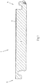
- FIG. 1 shows a panel 1 of a system of similar panels for the formation of a deposit.
- the panel 1 is a floor panel with a carrier layer 2 of a wood material.
- a non-descript decorative cover layer is provided at the top 3 of the panel 1.
- the panel 1 is rectangular and has a first side edge 4 and a second side edge 5 opposite each other.
- the first side edge 4 and the second side edge 5 have corresponding profiles, so that the similar panels 1 of the system can be connected to one another to form a floor covering.
- the third side edge of the illustrated and so far preferred panel 1 is formed similarly with the first side edge 4, while the fourth side edge of the panel is formed similar to the second side edge 5.
- the third side edge and the fourth side edge could also have profiles that differ significantly from those of the first side edge 4 and the second side edge 5.
- the first side edge 4 and the second side edge 5 are formed so that the second side edge 5 of a panel 1 of the system can be connected by a movement B substantially from top to bottom with the second side edge 5 of another panel 1 of the system. This is especially true in the Fig. 2 shown.
- the profile of the side edges 4, 5 extends essentially over the entire length of the respective side edge 4, 5.
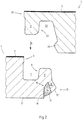
- the first side edge 4 has an upper edge 6 adjacent to the upper side 3 of the panel 1 in the panel 1 shown and preferred to that extent.
- an upwardly open fitting groove 7 connects.
- the outer groove flank 8 of the fitting groove 7, which is located on the first side edge 4 is formed by a locking spring 9 which extends upwards in the direction of the plane of the upper side 3 of the panel 1. Integral with the locking spring 9 is a Locking bar 10 is formed, which projects downward in the direction of the ground.
- the locking bolt 10 is slightly inclined with respect to the first side edge 4 in this direction to the outside.
- the locking bar 10 protrudes outwards as a result of this inclination and forms the distal end of the first side edge 4 in a direction perpendicular to the first side edge 4 and parallel to the panel 1.
- a locking surface 12 is provided at the downwardly facing free end 11 of the locking bolt 10. Adjacent to the free end 11 of the locking bolt 10, this has an edge 13 which is connected to a spring means 14 in the form of an elastic mass.
- the elastic mass is an elastic adhesive which is glued to the flank 13 of the locking bolt 10 which points inwardly with respect to the first side edge 4.
- inwardly facing flank 13 of the locking bolt 10 forms in the illustrated and so far preferred panel 1 a groove flank of a subsequent to the locking bolt 10 Elastizticiansnut 15.
- the spring means 14 is introduced into this elasticity groove 15 and flat with the groove flanks 13th , 16 and glued to the groove bottom.
- the inner groove flank 16 merges with the illustrated preferred embodiment of the panel 1 into the underside 17 of the panel 1, which rests on the substrate.
- the second side edge 5 has, corresponding to the first side edge 4 of the illustrated panel 1, an upper edge 20, which adjoins the top 3 of the panel 1, on. From top to bottom, one of the upper edge 20 subsequent key 21 extends, which is designed to engage in the fitting groove 7.
- the inner edge 22 of the feather key 21 relative to the second side edge 5 is provided as part of a locking groove 23 which is designed to receive the locking spring 9 of the first side edge 4.
- the locking groove 23 has a locking element 24, which limits the locking groove 23 in the illustrated and so far preferred panel 1 and merges into the underside 17 of the panel 1.
- a first stop surface 30 of the locking bolt 10 comes into contact with a second stop surface 31 of the locking element 24, which presses the locking bolt 10 from an outer position to an inner position relative to the first side edge 4.
- the locking bar 10 is bent relative to the first side edge 4 inwardly and the spring means 14 compressed in the elasticity 15.
- the locking bar 10 and the spring means 14 are slightly spaced from the base of the pad, so that both can be easily deformed when connecting.
- the first stop surface 30 and the second stop surface 31 are no longer abutting each other.
- the locking bar 10 is then moved as a result of the restoring force of the spring means 14 and the restoring force of the locking bolt 10 itself in the direction of the outer position.
- the locking bolt 10 and the locking element 24 lock together in a direction perpendicular to the pavement. If the locking bar 10 breaks during the connection by bending into the inner position, the spring means 14 ensures the movement of the locking bolt 10 in the direction of the outer position.
- first side edge 4 and second side edge 5 engages the key 21 in the fitting groove 7 a.
- a first mating surface 32 and a third mating surface 33 of the first side edge 4 come into abutment with a second mating surface 34 and a fourth mating surface 35 of the second side edge 5.
- the third and fourth mating surface 33, 35 are each in the region of an upper edge 6, 20 of the corresponding panel 1 is provided.
- the first mating surface 32 is provided at the outer groove flank 8 of the fitting groove 7 relative to the first side edge 4, while the second fitting surface 34 is provided at the inner flank 22 of the feather key 21 relative to the second side edge 5.
- the abutment of the first fitting surface 32 and the second fitting surface 34 against each other results in a locking of the first side edge 4 and the second side edge 5 in a direction parallel to the floor covering and perpendicular to the side edges 4, 5.
- the first side edge 4 is slightly bent in the region of the locking spring 9 down. This will caused by a slight excess of the feather key 21 with respect to the fitting groove 7.
- the second mating surface 34 is slightly, for example 5 °, inclined relative to the vertical, so that the second mating surface in the direction of the free end of the key 21 to the outside, ie to the edge of the panel runs.
- the first mating surface 32 is formed perpendicular to the covering. But she can also be inclined.
- a first abutment surface 36 is provided which is in abutment with a second abutment surface 37 at the distal end of the key 21.
- the second side edge 5 is supported downward relative to the first side edge 4.
- one pair of surfaces for supporting the second side edge 5 with respect to the first side edge 4 and vice versa is provided.
- the locking surfaces 12,38 are formed corresponding to each other and significantly inclined to the pad.
- the locking surface 12 of the locking bolt 10 extends upward from its inner end.
- the locking surface 38 of the locking member 24 extends downwardly as seen from its inner end.
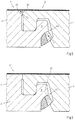
- Fig. 5 is the connection of a first side edge 4 and a second side edge 5 according to Fig. 4 shown, but with the difference that the locking bar 10 is broken when connecting.
- the first and the second side edge 4,5 are formed so that the locking bar 10 breaks approximately perpendicular to its longitudinal extension.
- the breaking edges 40 are then aligned approximately at right angles to the normal force F 1 acting on the locking bar 10 as a result of a lifting of the second side edge 5.
- F 1 acting on the locking bar 10
- the locking bar 10 is securely supported despite break against the first side edge 4.
- the locking bar 10 is supported not only upwards, but also inwardly relative to the first side edge 4, whereby the connection is further stabilized.
- Fig. 6 is a pair of interconnected panels 1 'shown, with respect to the configuration of the first side edge 4', in particular of the panel 1 ', the locking bolt 10 of the panels 1 according to Fig. 5 differ.
- the locking bar 10 ' formed in two pieces with the carrier layer 2' and the locking spring 9 '.
- the locking bolt 10 ' is made of plastic.
- the locking bar 10 ' has been manufactured together with the spring means 14 by coextrusion.
- the locking bar 10 'and the spring means 14 have been in one step with the coextrusion of the locking bar 10' and the spring means 14 to the support layer 2 'extruded.
- the locking bar 10 'could also be glued to the carrier layer 2'.
- the locking bar 10 'and / or the carrier layer 2' in the connection region 41 each have an intermeshing groove 42 parallel to the longitudinal extent of the first side edge 4.
Landscapes
- Engineering & Computer Science (AREA)
- Architecture (AREA)
- Civil Engineering (AREA)
- Structural Engineering (AREA)
- Floor Finish (AREA)
Priority Applications (1)
| Application Number | Priority Date | Filing Date | Title |
|---|---|---|---|
| PL11710473T PL2550415T3 (pl) | 2010-03-23 | 2011-03-21 | Układ co najmniej dwóch paneli |
Applications Claiming Priority (2)
| Application Number | Priority Date | Filing Date | Title |
|---|---|---|---|
| DE102010012572A DE102010012572B3 (de) | 2010-03-23 | 2010-03-23 | System von wenigstens zwei Paneelen |
| PCT/EP2011/054211 WO2011117179A1 (de) | 2010-03-23 | 2011-03-21 | System von wenigstens zwei paneelen |
Publications (2)
| Publication Number | Publication Date |
|---|---|
| EP2550415A1 EP2550415A1 (de) | 2013-01-30 |
| EP2550415B1 true EP2550415B1 (de) | 2018-02-07 |
Family
ID=43971311
Family Applications (1)
| Application Number | Title | Priority Date | Filing Date |
|---|---|---|---|
| EP11710473.7A Active EP2550415B1 (de) | 2010-03-23 | 2011-03-21 | System aus wenigstens zwei paneelen |
Country Status (7)
| Country | Link |
|---|---|
| US (1) | US8707651B2 (pl) |
| EP (1) | EP2550415B1 (pl) |
| DE (1) | DE102010012572B3 (pl) |
| ES (1) | ES2667499T3 (pl) |
| PL (1) | PL2550415T3 (pl) |
| RU (1) | RU2521262C2 (pl) |
| WO (1) | WO2011117179A1 (pl) |
Families Citing this family (30)
| Publication number | Priority date | Publication date | Assignee | Title |
|---|---|---|---|---|
| US11725395B2 (en) | 2009-09-04 | 2023-08-15 | Välinge Innovation AB | Resilient floor |
| EP2473687B1 (en) | 2009-09-04 | 2019-04-24 | Välinge Innovation AB | A method of assembling resilient floorboards which are provided with a mechanical locking system |
| US8365499B2 (en) | 2009-09-04 | 2013-02-05 | Valinge Innovation Ab | Resilient floor |
| EP4092213B1 (en) | 2010-01-11 | 2023-12-13 | Välinge Innovation AB | Floor covering with interlocking design |
| RU2548251C2 (ru) | 2010-01-14 | 2015-04-20 | Спанолюкс Н.В.-Див. Бальтерио | Блок напольных панелей и использующаяся в нем напольная панель |
| WO2011127981A1 (en) | 2010-04-15 | 2011-10-20 | Spanolux N.V.- Div. Balterio | Floor panel assembly |
| US8806832B2 (en) | 2011-03-18 | 2014-08-19 | Inotec Global Limited | Vertical joint system and associated surface covering system |
| UA114715C2 (uk) | 2011-07-05 | 2017-07-25 | Сералок Інновейшн Аб | Механічна фіксація панелей настилу підлоги до язичка з нанесеним шаром клею |
| US9725912B2 (en) | 2011-07-11 | 2017-08-08 | Ceraloc Innovation Ab | Mechanical locking system for floor panels |
| US8763340B2 (en) | 2011-08-15 | 2014-07-01 | Valinge Flooring Technology Ab | Mechanical locking system for floor panels |
| US8857126B2 (en) | 2011-08-15 | 2014-10-14 | Valinge Flooring Technology Ab | Mechanical locking system for floor panels |
| US8769905B2 (en) | 2011-08-15 | 2014-07-08 | Valinge Flooring Technology Ab | Mechanical locking system for floor panels |
| DE102011121348A1 (de) * | 2011-12-19 | 2013-06-20 | Fritz Egger Gmbh & Co. Og | Paneel eines Fußbodenbelags mit einer entlang einer Seitenkante geneigten Verriegelungsfläche |
| US9216541B2 (en) | 2012-04-04 | 2015-12-22 | Valinge Innovation Ab | Method for producing a mechanical locking system for building panels |
| US8596013B2 (en) * | 2012-04-04 | 2013-12-03 | Valinge Innovation Ab | Building panel with a mechanical locking system |
| WO2014033628A1 (en) | 2012-08-27 | 2014-03-06 | Pergo (Europe) Ab | Panel |
| CN104870726B (zh) * | 2012-09-19 | 2017-11-07 | 依诺泰克环球有限公司 | 饰面板材及相关锁扣系统 |
| DE102013100345B4 (de) * | 2013-01-14 | 2023-07-06 | Guido Schulte | Belag aus mechanisch miteinander verbindbaren Elementen |
| PT3358101T (pt) | 2013-03-25 | 2020-01-21 | Vaelinge Innovation Ab | Tábuas de piso providas de um sistema de bloqueio mecânico e método para produzir um sistema de bloqueio deste tipo |
| US10060139B2 (en) | 2013-07-09 | 2018-08-28 | Ceraloc Innovation Ab | Mechanical locking system for floor panels |
| RU2662745C2 (ru) | 2013-10-25 | 2018-07-30 | Сералок Инновейшн Аб | Механическая замковая система для панелей пола |
| WO2015070890A1 (en) | 2013-11-12 | 2015-05-21 | Grigorij Wagner | Flooring component |
| US10316526B2 (en) * | 2014-08-29 | 2019-06-11 | Valinge Innovation Ab | Vertical joint system for a surface covering panel |
| WO2017105335A1 (en) | 2015-12-17 | 2017-06-22 | Välinge Innovation AB | A method for producing a mechanical locking system for panels |
| US10287777B2 (en) | 2016-09-30 | 2019-05-14 | Valinge Innovation Ab | Set of panels |
| HRP20230520T1 (hr) | 2018-01-09 | 2023-08-04 | Välinge Innovation AB | Skup ploča |
| ES2965246T3 (es) | 2018-06-13 | 2024-04-11 | Ceraloc Innovation Ab | Sistema de pavimento provisto de un sistema de conexión y un dispositivo de conexión asociado |
| CN110029793A (zh) * | 2019-05-17 | 2019-07-19 | 浙江菱格木业有限公司 | 一种镶嵌式鱼骨拼地板的拼装结构 |
| EP4034730B1 (en) | 2019-09-23 | 2025-05-07 | Unilin, BV | Floor or wall covering |
| CA3153635A1 (en) * | 2019-09-25 | 2021-04-01 | Valinge Innovation Ab | Panel with locking device |
Citations (1)
| Publication number | Priority date | Publication date | Assignee | Title |
|---|---|---|---|---|
| WO2008060232A1 (en) * | 2006-11-15 | 2008-05-22 | Välinge Innovation AB | Mechanical locking of floor panels with vertical folding |
Family Cites Families (15)
| Publication number | Priority date | Publication date | Assignee | Title |
|---|---|---|---|---|
| BE1010487A6 (nl) | 1996-06-11 | 1998-10-06 | Unilin Beheer Bv | Vloerbekleding bestaande uit harde vloerpanelen en werkwijze voor het vervaardigen van dergelijke vloerpanelen. |
| DE10231921A1 (de) * | 2002-06-28 | 2004-01-22 | E.F.P. Floor Products Fussböden GmbH | Paneel eines Fußbodensystems, insbesondere eines Laminatfußbodens |
| DE102006011887A1 (de) * | 2006-01-13 | 2007-07-19 | Akzenta Paneele + Profile Gmbh | Sperrelement, Paneel mit separatem Sperrelement, Verfahren zur Installation eines Paneelbelags aus Paneelen mit Sperrelementen sowie Verfahren und Vorrichtung zur Vormontage eines Sperrelements an einem Paneel |
| DE102007019786B4 (de) * | 2006-12-22 | 2013-05-08 | Hamberger Industriewerke Gmbh | Verbindung für plattenförmige Bauelemente |
| DE202007000310U1 (de) * | 2007-01-03 | 2007-04-19 | Akzenta Paneele + Profile Gmbh | Paneel sowie Bodenbelag |
| DE102007015048B4 (de) * | 2007-03-26 | 2009-03-05 | Kronotec Ag | Paneel, insbesondere Bodenpaneel |
| DE102007032885B4 (de) * | 2007-07-14 | 2016-01-14 | Flooring Technologies Ltd. | Paneel, insbesondere Bodenpaneel und Einrichtung zum Verriegeln miteinander verbundener Paneele |
| BE1018600A5 (nl) | 2007-11-23 | 2011-04-05 | Flooring Ind Ltd Sarl | Vloerpaneel. |
| DE102007062430B3 (de) | 2007-12-20 | 2009-07-02 | Flooring Technologies Ltd. | Verfahren zum spanabhebenden Bearbeiten einer Seitenkante eines Paneels und Vorrichtung zum Durchführen des Verfahrens |
| US8037656B2 (en) * | 2008-08-08 | 2011-10-18 | Liu David C | Flooring boards with press down locking mechanism |
| EP2208835B1 (de) * | 2009-01-16 | 2012-05-30 | Flooring Technologies Ltd. | Paneel, insbesondere Fussbodenpaneel |
| DE102009035275A1 (de) * | 2009-06-08 | 2010-12-09 | Fritz Egger Gmbh & Co. | Paneel eines Fußbodensystems |
| BE1018802A3 (nl) * | 2009-06-29 | 2011-09-06 | Flooring Ind Ltd Sarl | Paneel, meer speciaal vloerpaneel. |
| DE102009048050B3 (de) * | 2009-10-02 | 2011-01-20 | Guido Schulte | Belag aus mechanischen miteinander verbindbaren Elementen |
| KR101245963B1 (ko) * | 2010-03-02 | 2013-03-21 | 오광석 | 바닥재 및 이에 이용되는 회전체 |
-
2010
- 2010-03-23 DE DE102010012572A patent/DE102010012572B3/de active Active
-
2011
- 2011-03-21 EP EP11710473.7A patent/EP2550415B1/de active Active
- 2011-03-21 RU RU2012144835/03A patent/RU2521262C2/ru active
- 2011-03-21 WO PCT/EP2011/054211 patent/WO2011117179A1/de not_active Ceased
- 2011-03-21 ES ES11710473.7T patent/ES2667499T3/es active Active
- 2011-03-21 US US13/636,455 patent/US8707651B2/en active Active
- 2011-03-21 PL PL11710473T patent/PL2550415T3/pl unknown
Patent Citations (1)
| Publication number | Priority date | Publication date | Assignee | Title |
|---|---|---|---|---|
| WO2008060232A1 (en) * | 2006-11-15 | 2008-05-22 | Välinge Innovation AB | Mechanical locking of floor panels with vertical folding |
Also Published As
| Publication number | Publication date |
|---|---|
| DE102010012572B3 (de) | 2011-07-14 |
| WO2011117179A1 (de) | 2011-09-29 |
| ES2667499T3 (es) | 2018-05-11 |
| RU2521262C2 (ru) | 2014-06-27 |
| EP2550415A1 (de) | 2013-01-30 |
| RU2012144835A (ru) | 2014-04-27 |
| US8707651B2 (en) | 2014-04-29 |
| PL2550415T3 (pl) | 2018-07-31 |
| US20130160390A1 (en) | 2013-06-27 |
Similar Documents
| Publication | Publication Date | Title |
|---|---|---|
| EP2550415B1 (de) | System aus wenigstens zwei paneelen | |
| DE102009048050B3 (de) | Belag aus mechanischen miteinander verbindbaren Elementen | |
| EP2459818B1 (de) | Belag aus mechanisch miteinander verbindbaren paneelen | |
| EP3150083B1 (de) | Einrichtung zum winkligen verbinden und verriegeln zweier platten, insbesondere möbelplatten | |
| EP2795017B1 (de) | Paneel eines fussbodenbelags mit einer entlang einer seitenkante geneigten verriegelungsfläche | |
| DE212010000195U1 (de) | Bodenplattenanordnung | |
| DE20002413U1 (de) | Verbindung | |
| WO2006050928A1 (de) | Verkleidungspaneel | |
| WO2002001018A1 (de) | Fussbodenplatte | |
| DE10243196A1 (de) | Paneele mit Verbindungsklammer | |
| DE10302727A1 (de) | Formschlüssiges Profil mit zwei Radien | |
| WO2010128043A1 (de) | Verriegelungssystem für paneele | |
| DE10305695B4 (de) | Verkleidungsplatte, insbesondere Fussbodenplatte | |
| EP2718516B1 (de) | Fussbodenpaneel mit einer einen Sperrriegel aufweisenden Seitenkante sowie Verfahren zum Verbinden für solche Fussbodenpaneele | |
| EP1922455A1 (de) | Paneel zum mechanischen verbinden mit einem weiteren paneel durch verschwenken | |
| EP2404012A1 (de) | Paneel zur bildung eines belags und verfahren zur herstellung eines solchen belags | |
| DE102013100345B4 (de) | Belag aus mechanisch miteinander verbindbaren Elementen | |
| EP2795016B1 (de) | Paneel eines fussbodenbelags mit fremdelement | |
| EP1702119A1 (de) | Einschwenkprofil | |
| EP2335525B1 (de) | Tisch mit Verbindungsanordnung | |
| DE102016105463B4 (de) | Mechanische Verbindung für Paneele | |
| WO2015086600A1 (de) | Paneel mit verriegelungselement | |
| EP2885470A1 (de) | Belag aus mechanisch miteinander verbindbaren elementen | |
| EP2403712A1 (de) | Leichtbauplatte sowie verfahren und vorrichtung zu deren herstellung | |
| DE202009011997U1 (de) | Paneel zur Bildung eines Belags |
Legal Events
| Date | Code | Title | Description |
|---|---|---|---|
| PUAI | Public reference made under article 153(3) epc to a published international application that has entered the european phase |
Free format text: ORIGINAL CODE: 0009012 |
|
| 17P | Request for examination filed |
Effective date: 20120919 |
|
| AK | Designated contracting states |
Kind code of ref document: A1 Designated state(s): AL AT BE BG CH CY CZ DE DK EE ES FI FR GB GR HR HU IE IS IT LI LT LU LV MC MK MT NL NO PL PT RO RS SE SI SK SM TR |
|
| DAX | Request for extension of the european patent (deleted) | ||
| 17Q | First examination report despatched |
Effective date: 20150504 |
|
| RAP1 | Party data changed (applicant data changed or rights of an application transferred) |
Owner name: FRITZ EGGER GMBH & CO. OG |
|
| GRAP | Despatch of communication of intention to grant a patent |
Free format text: ORIGINAL CODE: EPIDOSNIGR1 |
|
| INTG | Intention to grant announced |
Effective date: 20170516 |
|
| GRAJ | Information related to disapproval of communication of intention to grant by the applicant or resumption of examination proceedings by the epo deleted |
Free format text: ORIGINAL CODE: EPIDOSDIGR1 |
|
| INTC | Intention to grant announced (deleted) | ||
| GRAP | Despatch of communication of intention to grant a patent |
Free format text: ORIGINAL CODE: EPIDOSNIGR1 |
|
| INTG | Intention to grant announced |
Effective date: 20170822 |
|
| GRAS | Grant fee paid |
Free format text: ORIGINAL CODE: EPIDOSNIGR3 |
|
| GRAA | (expected) grant |
Free format text: ORIGINAL CODE: 0009210 |
|
| AK | Designated contracting states |
Kind code of ref document: B1 Designated state(s): AL AT BE BG CH CY CZ DE DK EE ES FI FR GB GR HR HU IE IS IT LI LT LU LV MC MK MT NL NO PL PT RO RS SE SI SK SM TR |
|
| REG | Reference to a national code |
Ref country code: GB Ref legal event code: FG4D Free format text: NOT ENGLISH |
|
| REG | Reference to a national code |
Ref country code: AT Ref legal event code: REF Ref document number: 968871 Country of ref document: AT Kind code of ref document: T Effective date: 20180215 Ref country code: CH Ref legal event code: EP |
|
| REG | Reference to a national code |
Ref country code: IE Ref legal event code: FG4D Free format text: LANGUAGE OF EP DOCUMENT: GERMAN |
|
| REG | Reference to a national code |
Ref country code: DE Ref legal event code: R096 Ref document number: 502011013685 Country of ref document: DE |
|
| REG | Reference to a national code |
Ref country code: RO Ref legal event code: EPE Ref country code: FR Ref legal event code: PLFP Year of fee payment: 8 |
|
| REG | Reference to a national code |
Ref country code: CH Ref legal event code: NV Representative=s name: SCHMAUDER AND PARTNER AG PATENT- UND MARKENANW, CH |
|
| REG | Reference to a national code |
Ref country code: ES Ref legal event code: FG2A Ref document number: 2667499 Country of ref document: ES Kind code of ref document: T3 Effective date: 20180511 |
|
| REG | Reference to a national code |
Ref country code: SE Ref legal event code: TRGR |
|
| REG | Reference to a national code |
Ref country code: NL Ref legal event code: FP |
|
| PG25 | Lapsed in a contracting state [announced via postgrant information from national office to epo] |
Ref country code: HR Free format text: LAPSE BECAUSE OF FAILURE TO SUBMIT A TRANSLATION OF THE DESCRIPTION OR TO PAY THE FEE WITHIN THE PRESCRIBED TIME-LIMIT Effective date: 20180207 Ref country code: NO Free format text: LAPSE BECAUSE OF FAILURE TO SUBMIT A TRANSLATION OF THE DESCRIPTION OR TO PAY THE FEE WITHIN THE PRESCRIBED TIME-LIMIT Effective date: 20180507 Ref country code: LT Free format text: LAPSE BECAUSE OF FAILURE TO SUBMIT A TRANSLATION OF THE DESCRIPTION OR TO PAY THE FEE WITHIN THE PRESCRIBED TIME-LIMIT Effective date: 20180207 Ref country code: FI Free format text: LAPSE BECAUSE OF FAILURE TO SUBMIT A TRANSLATION OF THE DESCRIPTION OR TO PAY THE FEE WITHIN THE PRESCRIBED TIME-LIMIT Effective date: 20180207 Ref country code: CY Free format text: LAPSE BECAUSE OF FAILURE TO SUBMIT A TRANSLATION OF THE DESCRIPTION OR TO PAY THE FEE WITHIN THE PRESCRIBED TIME-LIMIT Effective date: 20180207 |
|
| PG25 | Lapsed in a contracting state [announced via postgrant information from national office to epo] |
Ref country code: IS Free format text: LAPSE BECAUSE OF FAILURE TO SUBMIT A TRANSLATION OF THE DESCRIPTION OR TO PAY THE FEE WITHIN THE PRESCRIBED TIME-LIMIT Effective date: 20180607 Ref country code: LV Free format text: LAPSE BECAUSE OF FAILURE TO SUBMIT A TRANSLATION OF THE DESCRIPTION OR TO PAY THE FEE WITHIN THE PRESCRIBED TIME-LIMIT Effective date: 20180207 Ref country code: GR Free format text: LAPSE BECAUSE OF FAILURE TO SUBMIT A TRANSLATION OF THE DESCRIPTION OR TO PAY THE FEE WITHIN THE PRESCRIBED TIME-LIMIT Effective date: 20180508 Ref country code: RS Free format text: LAPSE BECAUSE OF FAILURE TO SUBMIT A TRANSLATION OF THE DESCRIPTION OR TO PAY THE FEE WITHIN THE PRESCRIBED TIME-LIMIT Effective date: 20180207 Ref country code: BG Free format text: LAPSE BECAUSE OF FAILURE TO SUBMIT A TRANSLATION OF THE DESCRIPTION OR TO PAY THE FEE WITHIN THE PRESCRIBED TIME-LIMIT Effective date: 20180507 |
|
| PG25 | Lapsed in a contracting state [announced via postgrant information from national office to epo] |
Ref country code: MT Free format text: LAPSE BECAUSE OF FAILURE TO SUBMIT A TRANSLATION OF THE DESCRIPTION OR TO PAY THE FEE WITHIN THE PRESCRIBED TIME-LIMIT Effective date: 20180207 |
|
| PG25 | Lapsed in a contracting state [announced via postgrant information from national office to epo] |
Ref country code: EE Free format text: LAPSE BECAUSE OF FAILURE TO SUBMIT A TRANSLATION OF THE DESCRIPTION OR TO PAY THE FEE WITHIN THE PRESCRIBED TIME-LIMIT Effective date: 20180207 Ref country code: AL Free format text: LAPSE BECAUSE OF FAILURE TO SUBMIT A TRANSLATION OF THE DESCRIPTION OR TO PAY THE FEE WITHIN THE PRESCRIBED TIME-LIMIT Effective date: 20180207 |
|
| REG | Reference to a national code |
Ref country code: DE Ref legal event code: R097 Ref document number: 502011013685 Country of ref document: DE |
|
| PG25 | Lapsed in a contracting state [announced via postgrant information from national office to epo] |
Ref country code: DK Free format text: LAPSE BECAUSE OF FAILURE TO SUBMIT A TRANSLATION OF THE DESCRIPTION OR TO PAY THE FEE WITHIN THE PRESCRIBED TIME-LIMIT Effective date: 20180207 Ref country code: MC Free format text: LAPSE BECAUSE OF FAILURE TO SUBMIT A TRANSLATION OF THE DESCRIPTION OR TO PAY THE FEE WITHIN THE PRESCRIBED TIME-LIMIT Effective date: 20180207 Ref country code: SK Free format text: LAPSE BECAUSE OF FAILURE TO SUBMIT A TRANSLATION OF THE DESCRIPTION OR TO PAY THE FEE WITHIN THE PRESCRIBED TIME-LIMIT Effective date: 20180207 Ref country code: SM Free format text: LAPSE BECAUSE OF FAILURE TO SUBMIT A TRANSLATION OF THE DESCRIPTION OR TO PAY THE FEE WITHIN THE PRESCRIBED TIME-LIMIT Effective date: 20180207 |
|
| PLBE | No opposition filed within time limit |
Free format text: ORIGINAL CODE: 0009261 |
|
| STAA | Information on the status of an ep patent application or granted ep patent |
Free format text: STATUS: NO OPPOSITION FILED WITHIN TIME LIMIT |
|
| REG | Reference to a national code |
Ref country code: IE Ref legal event code: MM4A |
|
| PG25 | Lapsed in a contracting state [announced via postgrant information from national office to epo] |
Ref country code: LU Free format text: LAPSE BECAUSE OF NON-PAYMENT OF DUE FEES Effective date: 20180321 |
|
| 26N | No opposition filed |
Effective date: 20181108 |
|
| PG25 | Lapsed in a contracting state [announced via postgrant information from national office to epo] |
Ref country code: IE Free format text: LAPSE BECAUSE OF NON-PAYMENT OF DUE FEES Effective date: 20180321 |
|
| PG25 | Lapsed in a contracting state [announced via postgrant information from national office to epo] |
Ref country code: SI Free format text: LAPSE BECAUSE OF FAILURE TO SUBMIT A TRANSLATION OF THE DESCRIPTION OR TO PAY THE FEE WITHIN THE PRESCRIBED TIME-LIMIT Effective date: 20180207 |
|
| PG25 | Lapsed in a contracting state [announced via postgrant information from national office to epo] |
Ref country code: PT Free format text: LAPSE BECAUSE OF FAILURE TO SUBMIT A TRANSLATION OF THE DESCRIPTION OR TO PAY THE FEE WITHIN THE PRESCRIBED TIME-LIMIT Effective date: 20180207 Ref country code: HU Free format text: LAPSE BECAUSE OF FAILURE TO SUBMIT A TRANSLATION OF THE DESCRIPTION OR TO PAY THE FEE WITHIN THE PRESCRIBED TIME-LIMIT; INVALID AB INITIO Effective date: 20110321 |
|
| PG25 | Lapsed in a contracting state [announced via postgrant information from national office to epo] |
Ref country code: MK Free format text: LAPSE BECAUSE OF NON-PAYMENT OF DUE FEES Effective date: 20180207 |
|
| PGFP | Annual fee paid to national office [announced via postgrant information from national office to epo] |
Ref country code: PL Payment date: 20250317 Year of fee payment: 15 Ref country code: CZ Payment date: 20250225 Year of fee payment: 15 |
|
| PGFP | Annual fee paid to national office [announced via postgrant information from national office to epo] |
Ref country code: IT Payment date: 20250325 Year of fee payment: 15 |
|
| PGFP | Annual fee paid to national office [announced via postgrant information from national office to epo] |
Ref country code: ES Payment date: 20250428 Year of fee payment: 15 |
|
| PGFP | Annual fee paid to national office [announced via postgrant information from national office to epo] |
Ref country code: CH Payment date: 20250401 Year of fee payment: 15 |
|
| REG | Reference to a national code |
Ref country code: CH Ref legal event code: U11 Free format text: ST27 STATUS EVENT CODE: U-0-0-U10-U11 (AS PROVIDED BY THE NATIONAL OFFICE) Effective date: 20260401 |
|
| PGFP | Annual fee paid to national office [announced via postgrant information from national office to epo] |
Ref country code: SE Payment date: 20260327 Year of fee payment: 16 |
|
| PGFP | Annual fee paid to national office [announced via postgrant information from national office to epo] |
Ref country code: GB Payment date: 20260326 Year of fee payment: 16 |
|
| PGFP | Annual fee paid to national office [announced via postgrant information from national office to epo] |
Ref country code: DE Payment date: 20260327 Year of fee payment: 16 |
|
| PGFP | Annual fee paid to national office [announced via postgrant information from national office to epo] |
Ref country code: AT Payment date: 20260327 Year of fee payment: 16 |
|
| PGFP | Annual fee paid to national office [announced via postgrant information from national office to epo] |
Ref country code: RO Payment date: 20260320 Year of fee payment: 16 Ref country code: BE Payment date: 20260326 Year of fee payment: 16 |
|
| PGFP | Annual fee paid to national office [announced via postgrant information from national office to epo] |
Ref country code: NL Payment date: 20260326 Year of fee payment: 16 |
|
| PGFP | Annual fee paid to national office [announced via postgrant information from national office to epo] |
Ref country code: FR Payment date: 20260326 Year of fee payment: 16 |
|
| PGFP | Annual fee paid to national office [announced via postgrant information from national office to epo] |
Ref country code: TR Payment date: 20260313 Year of fee payment: 16 |