EP2550415B1 - System of at least two panels - Google Patents
System of at least two panels Download PDFInfo
- Publication number
- EP2550415B1 EP2550415B1 EP11710473.7A EP11710473A EP2550415B1 EP 2550415 B1 EP2550415 B1 EP 2550415B1 EP 11710473 A EP11710473 A EP 11710473A EP 2550415 B1 EP2550415 B1 EP 2550415B1
- Authority
- EP
- European Patent Office
- Prior art keywords
- locking
- lateral edge
- locking member
- panel
- side edge
- Prior art date
- Legal status (The legal status is an assumption and is not a legal conclusion. Google has not performed a legal analysis and makes no representation as to the accuracy of the status listed.)
- Active
Links
- 230000013011 mating Effects 0.000 claims description 32
- 210000003746 feather Anatomy 0.000 claims description 18
- 239000002023 wood Substances 0.000 claims description 11
- 239000000463 material Substances 0.000 claims description 9
- 239000000853 adhesive Substances 0.000 claims description 3
- 230000001070 adhesive effect Effects 0.000 claims description 3
- 239000012876 carrier material Substances 0.000 claims description 2
- 238000000605 extraction Methods 0.000 description 3
- 239000000314 lubricant Substances 0.000 description 3
- 239000000123 paper Substances 0.000 description 3
- 239000004033 plastic Substances 0.000 description 3
- 239000007787 solid Substances 0.000 description 3
- 238000005452 bending Methods 0.000 description 2
- 239000011093 chipboard Substances 0.000 description 2
- 239000002131 composite material Substances 0.000 description 2
- 239000013013 elastic material Substances 0.000 description 2
- 239000011094 fiberboard Substances 0.000 description 2
- 239000003292 glue Substances 0.000 description 2
- 238000003801 milling Methods 0.000 description 2
- 238000013459 approach Methods 0.000 description 1
- 238000000418 atomic force spectrum Methods 0.000 description 1
- 230000015572 biosynthetic process Effects 0.000 description 1
- 239000011248 coating agent Substances 0.000 description 1
- 238000000576 coating method Methods 0.000 description 1
- 230000002349 favourable effect Effects 0.000 description 1
- 230000005484 gravity Effects 0.000 description 1
- 230000003993 interaction Effects 0.000 description 1
- 238000004519 manufacturing process Methods 0.000 description 1
- 230000000717 retained effect Effects 0.000 description 1
- 239000000758 substrate Substances 0.000 description 1
Images

Classifications
-
- E—FIXED CONSTRUCTIONS
- E04—BUILDING
- E04F—FINISHING WORK ON BUILDINGS, e.g. STAIRS, FLOORS
- E04F15/00—Flooring
- E04F15/02—Flooring or floor layers composed of a number of similar elements
-
- E—FIXED CONSTRUCTIONS
- E04—BUILDING
- E04F—FINISHING WORK ON BUILDINGS, e.g. STAIRS, FLOORS
- E04F2201/00—Joining sheets or plates or panels
- E04F2201/01—Joining sheets, plates or panels with edges in abutting relationship
- E04F2201/0138—Joining sheets, plates or panels with edges in abutting relationship by moving the sheets, plates or panels perpendicular to the main plane
- E04F2201/0146—Joining sheets, plates or panels with edges in abutting relationship by moving the sheets, plates or panels perpendicular to the main plane with snap action of the edge connectors
-
- E—FIXED CONSTRUCTIONS
- E04—BUILDING
- E04F—FINISHING WORK ON BUILDINGS, e.g. STAIRS, FLOORS
- E04F2201/00—Joining sheets or plates or panels
- E04F2201/04—Other details of tongues or grooves
- E04F2201/041—Tongues or grooves with slits or cuts for expansion or flexibility
-
- E—FIXED CONSTRUCTIONS
- E04—BUILDING
- E04F—FINISHING WORK ON BUILDINGS, e.g. STAIRS, FLOORS
- E04F2201/00—Joining sheets or plates or panels
- E04F2201/04—Other details of tongues or grooves
- E04F2201/044—Other details of tongues or grooves with tongues or grooves comprising elements which are not manufactured in one piece with the sheets, plates or panels but which are permanently fixedly connected to the sheets, plates or panels, e.g. at the factory
- E04F2201/049—Other details of tongues or grooves with tongues or grooves comprising elements which are not manufactured in one piece with the sheets, plates or panels but which are permanently fixedly connected to the sheets, plates or panels, e.g. at the factory wherein the elements are made of organic plastics with or without reinforcements or filling materials
-
- E—FIXED CONSTRUCTIONS
- E04—BUILDING
- E04F—FINISHING WORK ON BUILDINGS, e.g. STAIRS, FLOORS
- E04F2201/00—Joining sheets or plates or panels
- E04F2201/07—Joining sheets or plates or panels with connections using a special adhesive material
Definitions
- the invention relates to a system of at least two panels, in particular floor panels, for forming a covering, the two panels having a first side edge and a second side edge opposite the first side edge, the first side edge and the second side edge connecting the first side edge of a panel formed with the second side edge of another panel by a movement substantially perpendicular to the covering, wherein the first side edge has a locking bar and a spring means, wherein the second side edge has a locking element cooperating with the locking bar, wherein the locking bar in one piece from a carrier layer of the panel and is designed to be movable, so that the locking bolt can assume an outer position and an inner position relative to the first side edge, wherein the spring means is coupled to the locking bolt such that the spring means in the inner position a croqu restoring force on the locking latch in the direction of the outer position, wherein the locking bar and the locking element each having a locking surface, wherein the locking surface of the locking bar to the underside of the panel and is provided at a free end of the locking bar, wherein in
- Panels of this type can be connected to one another to form a floor covering, in particular floor covering.
- the first and second side edges of adjacent panels are therefore formed corresponding to each other.
- the joining of each of the first and the second side edges of adjacent panels is effected by a movement which is substantially perpendicular to the floor covering, in the case of a floor covering substantially vertically.
- the panels thus differ quite fundamentally from those in which the first and second side edges are incised into one another by means of a pivoting movement or are pushed into one another by a movement substantially parallel to the covering.
- Such panels are for example from the WO 97/47834 A1 known.
- the first and second side edges of the panels of the type mentioned have locking latch and locking elements which engage with each other in the connected state.
- the panels can then no longer against each other be lifted off to the top. So there is a locking substantially perpendicular to the covering.
- an additional locking of the panels can take place substantially parallel to the covering.
- the first and second side edges of the panels are therefore to be laid without the use of glue or other fasteners, such as screws or nails.
- floor panels are understood to mean, in particular, laminate floor panels.
- Laminated floor panels generally have at least one layer with a resin-soaked decorative paper and at least one counter-tensile layer with a likewise resin-impregnated paper on both sides of a so-called carrier layer.
- the base body of the panels forming carrier layer is made in particular of a wood material. Suitable wood-based materials are, for example, medium-density fiberboard (MDF), high-density fibreboard (HDF), chipboard or Oriented Strand Boards (OSB).
- MDF medium-density fiberboard
- HDF high-density fibreboard
- OSB Oriented Strand Boards
- solid wood a wood / plastic composite or a compact board made from pressed, resin-impregnated papers as a carrier material.
- Panels of the type mentioned are approximately from the EP 1 518 032 A1 known.
- the opposing first and second side edges of the panels are formed corresponding to each other.
- the second side edge can be connected to the first side edge from above, ie substantially perpendicular to the covering. In the connected state, the panels can not be lifted upwards, since it is at Connecting to a latching operation between a locking lip and a locking lug of the side edges comes.
- the locking lip and the locking lug are matched to one another such that the locking lug presses against the locking lip during connection.
- the locking lip has the necessary flexibility to consequently be pushed from an outer position relative to the first side edge to an inner position.
- the flexibility of the locking lip is provided by an elasticity groove adjacent to the locking lip, which may be filled with an elastic means as needed to adjust the flexibility.
- the locking lip If the locking lip is forced to the inner position, the locking lug can slide past the locking lip. Subsequently, the locking lip springs back into its outer position and engages behind the locking lug of the adjacent side edge. Thus, corresponding locking surfaces of locking lip and locking lug come into abutment with each other, which are each slightly inclined relative to the plane of the lining.
- the necessary elasticity of the locking bar for the spring back of the same is also provided, if necessary, essentially by the spring means.
- the locking lip is formed integrally with the carrier layer of the panel. When connecting two side edges, however, the locking lip may break. If the elastic means is a type of glue, the locking lip will remain on the panel despite such breakage fixed. The locking of the side edges perpendicular to the floor covering is retained. However, a connection with a broken locking lip can only absorb reduced vertical pull-out forces, depending on the elastic means. At high loads, it may therefore come to a height offset of the connected panels. If the load continues to increase, the panels may become disengaged due to the offset in height, or may permanently rupture the locking lip.
- Systems of panels with corresponding side edges to form floor coverings which can be connected by a substantially vertical movement to the floor covering and locked by means of a movable locking bolt are, for example, from WO 2011/001326 A2 and the WO 2009/080328 A1 known.
- the WO 2008/060232 A1 from which the invention proceeds, also has a spring means in the form of an elastic mass for adjusting the restoring force of the locking bolt.
- the invention is based on the technical problem to provide a system of panels of the type mentioned, with the higher vertical extraction forces can be ensured.
- the first and second side edges become substantially perpendicular to the covering to be produced from the panels by a movement in one direction connected.
- the connection of the first and second side edges does not have to be exactly perpendicular to the covering. It is sufficient if the movement for connecting the first and the second side edges runs predominantly from top to bottom.
- a movement essentially perpendicular to the covering can be understood to mean a movement which runs predominantly perpendicularly (> 45 °) to the covering. However, the movement will preferably have an angle of> 70 ° to the covering.
- the first and the second side edge can also be connected by a pivoting movement about another side edge.
- one end of the first side edge may be in engagement with the second side edge rather than the other end of the first side edge.
- the second side edge is pushed from the top to the first side edge.
- the locking bar having first side edge is preferably already on the ground.
- the locking member then approaches the locking latch from above and pushes the locking latch against the panel from the outer position to the inner position. If the locking element has passed the locking bar, this is pressed by the spring means in the direction of the possibly original, outer position, so that the locking bolt and the locking element lock together. In the connected state, the locking element engages under the locking latch.
- a movement from top to bottom does not necessarily mean a movement in the direction of gravity, although this will certainly be the case with floor panels.
- a movement from top to bottom does not necessarily mean a movement in the direction of gravity, although this will certainly be the case with floor panels.
- the surface of the covering to be produced indicates.
- the back of the pavement to be made points are generally where the back of the pavement to be made points.
- connection pull-in forces which lift the second side edge opposite the first side edge, this movement is blocked by the abutting locking surfaces of locking latch and locking lug.
- the locking bar Since the locking bar is supported relative to the panel, high extraction forces can be absorbed by the connection in this way, even if the locking bar breaks when connecting the side edges.
- the locking bolt is namely pressed against the panel. Should the locking bolt break when connecting the side edges or for any other reason, preferably at the same time resulting in the breaking of the locking bar break edges are pressed together.
- the locking bar It is advisable for a permanent locking of the side edges, to manufacture the locking bar of a material or with such dimensions that it is not excessively compressed. It also makes sense if the locking bar is supported against a part of the first side edge, which can absorb the forces introduced via the locking bar, without being unduly deformed or destroyed. The corresponding part of the first side edge therefore points as well as the locking bar preferably has a high rigidity and strength.
- the locking bar may be formed so that it breaks in an excessive load in a predictable manner. It can therefore be provided a kind of predetermined breaking point.
- the locking bolt may be formed so that a possible fracture plane extends at an obtuse angle to the force acting on the locking bolt when lifting the second side edge. The sharper this angle is, the higher is the risk that the two break edges created by the break will slip against each other and the first and second side edges will no longer be locked perpendicularly to the lining.
- the locking surface of the locking bar faces downward, i. to the bottom of the panel.
- the locking bar is pressed up against the panel. In this way, high extraction forces can be absorbed by the connection between a first and a second side edge even with a broken locking bolt.
- the locking surface of the locking element facing upward ie to the surface of the panel.
- the locking surface of the locking bolt and / or the locking element is inclined relative to the plane of the lining, namely in opposite directions, so that the locking bolt is pressed in relation to the first side edge inwardly.
- the inclination of the locking surface of the locking bolt and / or of the locking element is preferably less than 45 ° for a favorable force curve.
- the locking surfaces are formed corresponding to each other.
- the locking surfaces of the locking bolt and the locking element are pressed against each other in the connected state.
- a bias between the locking surfaces of locking latch and locking element By pressing against each other of the locking surfaces a frictional connection is achieved in the connection of the first and second side edge.
- the bias or the frictional connection can be achieved for example by a wedge-shaped contact of the locking surfaces together.
- the spring means permanently exerts a restoring force on the locking bolt, for example because this does not return to its original outer position when locking.
- the locking bar For a secure support of the locking bar on the first side edge of the locking surface of the locking bar is provided at a free end thereof.
- the opposite in the longitudinal extent of the locking bolt end of the locking bar this is preferably connected to the first side edge and / or supported against this.
- the locking bar extends between the end connected to the carrier layer and the free end predominantly perpendicular to the panel.
- the locking bolt is also in this direction relative to the first side edge inclined outwards, so that the locking bar is supported upwards and at the same time slightly inwardly relative to the first side edge.
- the inclination of the locking bar may expediently be between 15 ° and 35 °, in particular between 20 ° and 35 °.
- the spring means is connected to the locking bolt.
- the spring means for the same reason on the inside of the locking bar relative to the panel is arranged.
- the spring means may be provided in a simple manner between the free end and the end connected to the panel of the locking bolt.
- the locking bar can form a flank of a groove in which the spring means is received.
- the spring means can then be particularly easily introduced into the groove when it is open at the bottom.
- the spring means is materially connected to the locking bolt, preferably glued, is.
- the spring means may be an elastic adhesive in a simple embodiment. Irrespective of this, the spring means is preferably designed so elastically that on the one hand it does not oppose the movement of the locking bolt from the outer position to the inner position to high resistance and on the other hand exerts a sufficient restoring force on the locking bolt in the direction of the outer position.
- the spring means is formed as an elastic mass.
- the locking bar is integrally formed with the carrier layer of the panel. There is no connection area, which could be a weak point under mechanical stress.
- the carrier layer is preferably formed from a wood material. In this context, it makes sense if the locking bar is milled out of the carrier layer. Preferably, a groove is then milled out of the carrier layer adjacent to the locking bar, which serves to receive the spring means.
- the support layer is preferably formed from a wood material for receiving high forces. Suitable wood-based materials are, for example, medium-density fiberboard (MDF), high-density fibreboard (HDF), chipboard or Oriented Strand Boards (OSB). If required, the carrier layer can also be formed from solid wood, a wood / plastic composite or a compact plate.
- MDF medium-density fiberboard
- HDF high-density fibreboard
- OSB Oriented Strand Boards
- the carrier layer can also be formed from solid wood, a wood / plastic composite or a compact plate.
- the locking bar may have a first stop surface and the locking element may have a second stop surface, which abut each other when two panels are connected, thereby forcing the locking bar from the outer position to the inner position.
- the first stop surface may face outward with respect to the first side edge.
- a further reduction in the force required for connecting can be achieved by providing a lubricant on at least one of the two stop surfaces.
- the lubricant can be in shape be applied to a coating.
- the basis for the lubricant can be paraffins.
- a secure locking of the first and second side edge can be realized when the locking bar is provided on a locking spring, the second side edge has a locking groove and engages in the connected state, the locking spring in the locking groove. The locking bar is then supported against the locking spring. If the locking spring is sufficiently solid, greater pull-out forces can be dissipated via the locking spring.
- the locking bar forms the distal end of the first side edge in a direction parallel to the corresponding panel.
- the first side edge may have a fitting groove and the second side edge may have a feather key.
- the keyway preferably has a first mating surface on the groove flank facing the panel, while the key has a second mating surface on the spring flank facing the panel.
- the feather key can engage in the fitting groove, so that the first fitting surface bears against the second fitting face. The engagement of the key in the fitting groove acts to pull out the Panels in a direction perpendicular to the first and second side edge and parallel to the lining.
- a third fitting surface may be provided in the region of the upper edge of the first side and a fourth fitting surface in the region of the upper edge of the second side edge.
- the third and fourth mating surface abut each other in the connected state of the panels.
- the first fitting surface can be pushed slightly outwards in connecting the first and the second side edge with respect to the first side edge, without the first fitting surface in the connected state again the original position returns. Since the first side edge exerts a restoring force on the first mating surface, the first mating surface is pressed against the second mating surface.
- the fourth fitting surface can be pressed against the third, in order to achieve a frictional connection or a possible gap-free abutment of the panels in the region of the third and fourth mating surfaces. If, by connecting second side edges, certain surfaces of these side edges are pressed against one another, one speaks of a bias.
- this can be achieved, for example, by the feather key having a slight oversize relative to the fitting groove.
- the second mating surface has a slight inclination relative to the vertical to the panel, nevertheless to ensure a secure connection of feather key and keyway.
- the bias may be caused by a local deformation in the region of one or more mating surfaces or in less elastic materials by a slight bending of one, preferably the first side edge in elastic materials of the carrier layer.
- a first contact surface can be provided on the groove bottom of the fitting groove and a second contact surface on the distal end of the feather key.
- the first contact surface and the second contact surface are in the connected state to each other and thus the second side edge in the region of these contact surfaces on the first side edge.
- the fit groove between the locking bolt and the upper edge of the first side edge can be provided. If a locking spring is provided, it makes sense if the fitting groove is provided between the locking spring and the upper edge of the first side edge. In this case, the key is accordingly provided between the upper edge of the second side edge and the locking groove.
- coverings in particular floor coverings
- the panels can have a third side edge which is similar to the first one Side edge is formed.
- fourth side edges are preferably also provided, which are arranged opposite the third side edges and which are formed identically with the second side edge.
- panels can be provided which have similar profiles at the four circumferential side edges.
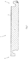
- FIG. 1 shows a panel 1 of a system of similar panels for the formation of a deposit.
- the panel 1 is a floor panel with a carrier layer 2 of a wood material.
- a non-descript decorative cover layer is provided at the top 3 of the panel 1.
- the panel 1 is rectangular and has a first side edge 4 and a second side edge 5 opposite each other.
- the first side edge 4 and the second side edge 5 have corresponding profiles, so that the similar panels 1 of the system can be connected to one another to form a floor covering.
- the third side edge of the illustrated and so far preferred panel 1 is formed similarly with the first side edge 4, while the fourth side edge of the panel is formed similar to the second side edge 5.
- the third side edge and the fourth side edge could also have profiles that differ significantly from those of the first side edge 4 and the second side edge 5.
- the first side edge 4 and the second side edge 5 are formed so that the second side edge 5 of a panel 1 of the system can be connected by a movement B substantially from top to bottom with the second side edge 5 of another panel 1 of the system. This is especially true in the Fig. 2 shown.
- the profile of the side edges 4, 5 extends essentially over the entire length of the respective side edge 4, 5.
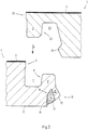
- the first side edge 4 has an upper edge 6 adjacent to the upper side 3 of the panel 1 in the panel 1 shown and preferred to that extent.
- an upwardly open fitting groove 7 connects.
- the outer groove flank 8 of the fitting groove 7, which is located on the first side edge 4 is formed by a locking spring 9 which extends upwards in the direction of the plane of the upper side 3 of the panel 1. Integral with the locking spring 9 is a Locking bar 10 is formed, which projects downward in the direction of the ground.
- the locking bolt 10 is slightly inclined with respect to the first side edge 4 in this direction to the outside.
- the locking bar 10 protrudes outwards as a result of this inclination and forms the distal end of the first side edge 4 in a direction perpendicular to the first side edge 4 and parallel to the panel 1.
- a locking surface 12 is provided at the downwardly facing free end 11 of the locking bolt 10. Adjacent to the free end 11 of the locking bolt 10, this has an edge 13 which is connected to a spring means 14 in the form of an elastic mass.
- the elastic mass is an elastic adhesive which is glued to the flank 13 of the locking bolt 10 which points inwardly with respect to the first side edge 4.
- inwardly facing flank 13 of the locking bolt 10 forms in the illustrated and so far preferred panel 1 a groove flank of a subsequent to the locking bolt 10 Elastizticiansnut 15.
- the spring means 14 is introduced into this elasticity groove 15 and flat with the groove flanks 13th , 16 and glued to the groove bottom.
- the inner groove flank 16 merges with the illustrated preferred embodiment of the panel 1 into the underside 17 of the panel 1, which rests on the substrate.
- the second side edge 5 has, corresponding to the first side edge 4 of the illustrated panel 1, an upper edge 20, which adjoins the top 3 of the panel 1, on. From top to bottom, one of the upper edge 20 subsequent key 21 extends, which is designed to engage in the fitting groove 7.
- the inner edge 22 of the feather key 21 relative to the second side edge 5 is provided as part of a locking groove 23 which is designed to receive the locking spring 9 of the first side edge 4.
- the locking groove 23 has a locking element 24, which limits the locking groove 23 in the illustrated and so far preferred panel 1 and merges into the underside 17 of the panel 1.
- a first stop surface 30 of the locking bolt 10 comes into contact with a second stop surface 31 of the locking element 24, which presses the locking bolt 10 from an outer position to an inner position relative to the first side edge 4.
- the locking bar 10 is bent relative to the first side edge 4 inwardly and the spring means 14 compressed in the elasticity 15.
- the locking bar 10 and the spring means 14 are slightly spaced from the base of the pad, so that both can be easily deformed when connecting.
- the first stop surface 30 and the second stop surface 31 are no longer abutting each other.
- the locking bar 10 is then moved as a result of the restoring force of the spring means 14 and the restoring force of the locking bolt 10 itself in the direction of the outer position.
- the locking bolt 10 and the locking element 24 lock together in a direction perpendicular to the pavement. If the locking bar 10 breaks during the connection by bending into the inner position, the spring means 14 ensures the movement of the locking bolt 10 in the direction of the outer position.
- first side edge 4 and second side edge 5 engages the key 21 in the fitting groove 7 a.
- a first mating surface 32 and a third mating surface 33 of the first side edge 4 come into abutment with a second mating surface 34 and a fourth mating surface 35 of the second side edge 5.
- the third and fourth mating surface 33, 35 are each in the region of an upper edge 6, 20 of the corresponding panel 1 is provided.
- the first mating surface 32 is provided at the outer groove flank 8 of the fitting groove 7 relative to the first side edge 4, while the second fitting surface 34 is provided at the inner flank 22 of the feather key 21 relative to the second side edge 5.
- the abutment of the first fitting surface 32 and the second fitting surface 34 against each other results in a locking of the first side edge 4 and the second side edge 5 in a direction parallel to the floor covering and perpendicular to the side edges 4, 5.
- the first side edge 4 is slightly bent in the region of the locking spring 9 down. This will caused by a slight excess of the feather key 21 with respect to the fitting groove 7.
- the second mating surface 34 is slightly, for example 5 °, inclined relative to the vertical, so that the second mating surface in the direction of the free end of the key 21 to the outside, ie to the edge of the panel runs.
- the first mating surface 32 is formed perpendicular to the covering. But she can also be inclined.
- a first abutment surface 36 is provided which is in abutment with a second abutment surface 37 at the distal end of the key 21.
- the second side edge 5 is supported downward relative to the first side edge 4.
- one pair of surfaces for supporting the second side edge 5 with respect to the first side edge 4 and vice versa is provided.
- the locking surfaces 12,38 are formed corresponding to each other and significantly inclined to the pad.
- the locking surface 12 of the locking bolt 10 extends upward from its inner end.
- the locking surface 38 of the locking member 24 extends downwardly as seen from its inner end.
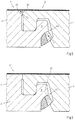
- Fig. 5 is the connection of a first side edge 4 and a second side edge 5 according to Fig. 4 shown, but with the difference that the locking bar 10 is broken when connecting.
- the first and the second side edge 4,5 are formed so that the locking bar 10 breaks approximately perpendicular to its longitudinal extension.
- the breaking edges 40 are then aligned approximately at right angles to the normal force F 1 acting on the locking bar 10 as a result of a lifting of the second side edge 5.
- F 1 acting on the locking bar 10
- the locking bar 10 is securely supported despite break against the first side edge 4.
- the locking bar 10 is supported not only upwards, but also inwardly relative to the first side edge 4, whereby the connection is further stabilized.
- Fig. 6 is a pair of interconnected panels 1 'shown, with respect to the configuration of the first side edge 4', in particular of the panel 1 ', the locking bolt 10 of the panels 1 according to Fig. 5 differ.
- the locking bar 10 ' formed in two pieces with the carrier layer 2' and the locking spring 9 '.
- the locking bolt 10 ' is made of plastic.
- the locking bar 10 ' has been manufactured together with the spring means 14 by coextrusion.
- the locking bar 10 'and the spring means 14 have been in one step with the coextrusion of the locking bar 10' and the spring means 14 to the support layer 2 'extruded.
- the locking bar 10 'could also be glued to the carrier layer 2'.
- the locking bar 10 'and / or the carrier layer 2' in the connection region 41 each have an intermeshing groove 42 parallel to the longitudinal extent of the first side edge 4.
Description
Die Erfindung betrifft ein System von wenigstens zwei Paneelen, insbesondere Fußbodenpaneelen, zur Bildung eines Belags, wobei die beiden Paneele eine erste Seitenkante und eine der ersten Seitenkante gegenüberliegende zweite Seitenkante aufweisen, wobei die erste Seitenkante und die zweite Seitenkante zum Verbinden der ersten Seitenkante eines Paneels mit der zweiten Seitenkante eines anderen Paneels durch eine Bewegung im Wesentlichen senkrecht zum Belag ausgebildet sind, wobei die erste Seitenkante einen Sperrriegel und ein Federmittel aufweist, wobei die zweite Seitenkante ein mit dem Sperrriegel zusammenwirkendes Verriegelungselement aufweist, wobei der Sperrriegel einstückig aus einer Trägerschicht des Paneels und beweglich ausgebildet ist, so dass der Sperrriegel bezogen auf die erste Seitenkante eine äußere Position und eine innere Position einnehmen kann, wobei das Federmittel derart mit dem Sperrriegel gekoppelt ist, dass das Federmittel in der inneren Position eine Rückstellkraft auf den Sperrriegel in Richtung der äußeren Position ausübt, wobei der Sperrriegel und das Verriegelungselement jeweils eine Verriegelungsfläche aufweisen, wobei die Verriegelungsfläche des Sperrriegels zur Unterseite des Paneels weist und an einem freien Ende des Sperrriegels vorgesehen ist, wobei im verbundenen Zustand die Verriegelungsflächen des Verriegelungselements und des Sperrriegels in der äußeren Position aneinander anliegen,
wobei die erste Seitenkante und die zweite Seitenkante zum Verbinden untereinander durch eine von oben nach unten gerichtete Bewegung der zweiten Seitenkante ausgebildet sind, wobei der Sperrriegel zwischen dem mit der Trägerschicht verbundenen Ende und dem freien Ende sich in einer Richtung überwiegend senkrecht zum Paneel erstreckt und bezogen auf die erste Seitenkante nach außen geneigt ist, wobei das Federmittel in Form einer elastischen Masse ausgebildet ist und wobei die Verriegelungsflächen des Sperrriegels und des Verriegelungselements im verbundenen Zustand die zweite Seitenkante gegenüber einem Abheben nach oben verriegelt, während sich der Sperrriegel nach oben und gleichzeitig leicht nach innen bezogen auf die erste Seitenkante gegenüber dem Paneel abstützt und dabei nach oben gegen das Paneel gedrückt wird.The invention relates to a system of at least two panels, in particular floor panels, for forming a covering, the two panels having a first side edge and a second side edge opposite the first side edge, the first side edge and the second side edge connecting the first side edge of a panel formed with the second side edge of another panel by a movement substantially perpendicular to the covering, wherein the first side edge has a locking bar and a spring means, wherein the second side edge has a locking element cooperating with the locking bar, wherein the locking bar in one piece from a carrier layer of the panel and is designed to be movable, so that the locking bolt can assume an outer position and an inner position relative to the first side edge, wherein the spring means is coupled to the locking bolt such that the spring means in the inner position a Rü restoring force on the locking latch in the direction of the outer position, wherein the locking bar and the locking element each having a locking surface, wherein the locking surface of the locking bar to the underside of the panel and is provided at a free end of the locking bar, wherein in the connected state, the locking surfaces of the locking element and the locking bar abut each other in the outer position,
wherein the first side edge and the second side edge are adapted to be interconnected by a top-to-bottom movement of the second side edge, the locking bar being interposed therebetween with the support layer connected end and the free end extends in a direction predominantly perpendicular to the panel and is inclined with respect to the first side edge to the outside, wherein the spring means is in the form of an elastic mass and wherein the locking surfaces of the locking bolt and the locking element in the connected state, the second Side edge locked against lifting upwards, while the locking bar is supported upwards and at the same time slightly inwardly relative to the first side edge opposite the panel and is pressed up against the panel.
Paneele dieser Art können untereinander zu einem Belag, insbesondere Fußbodenbelag, verbunden werden. Die ersten und zweiten Seitenkanten angrenzender Paneele sind deshalb korrespondierend zueinander ausgebildet. Das Verbinden jeweils der ersten und der zweiten Seitenkanten benachbarter Paneele erfolgt durch eine Bewegung, die im Wesentlichen senkrecht zum Bodenbelag, im Falle eines Fußbodenbelags im Wesentlichen vertikal, verläuft.Panels of this type can be connected to one another to form a floor covering, in particular floor covering. The first and second side edges of adjacent panels are therefore formed corresponding to each other. The joining of each of the first and the second side edges of adjacent panels is effected by a movement which is substantially perpendicular to the floor covering, in the case of a floor covering substantially vertically.
Die Paneele unterscheiden sich also ganz grundsätzlich von solchen, bei denen die ersten und zweiten Seitenkanten mittels einer Schwenkbewegung ineinander eingewinkelt werden oder durch eine Bewegung im Wesentlichen parallel zum Belag ineinander geschoben werden. Derartige Paneele sind beispielsweise aus der
Die ersten und zweiten Seitenkanten der Paneele der eingangs genannten Art weisen Sperrriegel und Verriegelungselemente auf, die im verbundenen Zustand miteinander in Eingriff gelangen. Die Paneele können dann nicht mehr gegeneinander nach oben abgehoben werden. Es erfolgt also eine Verriegelung im Wesentlichen senkrecht zum Belag. Gleichzeitig oder durch andere Mittel kann zusätzlich eine Verriegelung der Paneele im Wesentlichen parallel zum Belag erfolgen. In der Regel sind die ersten und zweiten Seitenkanten der Paneele folglich ohne die Verwendung von Leim oder weiteren Befestigungselementen, wie Schrauben oder Nägel, zu verlegen.The first and second side edges of the panels of the type mentioned have locking latch and locking elements which engage with each other in the connected state. The panels can then no longer against each other be lifted off to the top. So there is a locking substantially perpendicular to the covering. At the same time or by other means, an additional locking of the panels can take place substantially parallel to the covering. As a rule, the first and second side edges of the panels are therefore to be laid without the use of glue or other fasteners, such as screws or nails.
Unter Fußbodenpaneelen werden vorliegend insbesondere Laminatfußbodenpaneele verstanden. Laminatfußbodenpaneele weisen in der Regel wenigstens eine Schicht mit einem harzgetränkten Dekorpapier und wenigstens eine Gegenzugschicht mit einem ebenfalls harzgetränkten Papier auf beiden Seiten einer sogenannten Trägerschicht auf. Bei Paneelen mit lackierten Oberflächen ist das Dekor auf die Trägerschicht oder eine weitere Schicht aufgedruckt.
Die den Grundkörper der Paneele bildende Trägerschicht ist insbesondere aus einem Holzwerkstoff gefertigt. Als Holzwerkstoffe kommen beispielsweise mitteldichte Faserplatten (MDF), hochdichte Faserplatten (HDF), Spanplatten oder Oriented Strand Boards (OSB) in Frage. Es können aber auch massives Holz, ein Holz-/Kunststoff-Verbund oder eine Compactplatte aus verpressten, harzgetränkten Papieren als Trägermaterial Verwendung finden.In the present case, floor panels are understood to mean, in particular, laminate floor panels. Laminated floor panels generally have at least one layer with a resin-soaked decorative paper and at least one counter-tensile layer with a likewise resin-impregnated paper on both sides of a so-called carrier layer. For panels with painted surfaces, the decor is printed on the backing or another layer.
The base body of the panels forming carrier layer is made in particular of a wood material. Suitable wood-based materials are, for example, medium-density fiberboard (MDF), high-density fibreboard (HDF), chipboard or Oriented Strand Boards (OSB). However, it is also possible to use solid wood, a wood / plastic composite or a compact board made from pressed, resin-impregnated papers as a carrier material.
Paneele der genannten Art sind etwa aus der
Die Verriegelungslippe und die Verriegelungsnase sind so aufeinander abgestimmt, dass die Verriegelungsnase beim Verbinden gegen die Verriegelungslippe drückt. Die Verriegelungslippe weist die nötige Flexibilität auf, um infolgedessen von einer in Bezug auf die erste Seitenkante äußeren Position in eine innere Position gedrückt zu werden. Die Flexibilität der Verriegelungslippe wird durch eine an die Verriegelungslippe angrenzende Elastizitätsnut bereitgestellt, die bedarfsweise zur Einstellung der Flexibilität mit einem elastischen Mittel gefüllt sein kann.The locking lip and the locking lug are matched to one another such that the locking lug presses against the locking lip during connection. The locking lip has the necessary flexibility to consequently be pushed from an outer position relative to the first side edge to an inner position. The flexibility of the locking lip is provided by an elasticity groove adjacent to the locking lip, which may be filled with an elastic means as needed to adjust the flexibility.
Ist die Verriegelungslippe in die innere Position gezwungen, kann die Verriegelungsnase an der Verriegelungslippe vorbei gleiten. Anschließend federt die Verriegelungslippe in ihre äußere Position zurück und hintergreift dabei die Verriegelungsnase der angrenzenden Seitenkante. So kommen korrespondierende Verriegelungsflächen von Verriegelungslippe und Verriegelungsnase in Anlage aneinander, die jeweils leicht gegenüber der Ebene des Belags geneigt sind. Die nötige Elastizität des Sperrriegels für das Zurückfedern desselben wird auch, bedarfsweise im Wesentlichen durch das Federmittel bereitgestellt.If the locking lip is forced to the inner position, the locking lug can slide past the locking lip. Subsequently, the locking lip springs back into its outer position and engages behind the locking lug of the adjacent side edge. Thus, corresponding locking surfaces of locking lip and locking lug come into abutment with each other, which are each slightly inclined relative to the plane of the lining. The necessary elasticity of the locking bar for the spring back of the same is also provided, if necessary, essentially by the spring means.
Die Verriegelungslippe ist einstückig mit der Trägerschicht des Paneels ausgebildet. Beim Verbinden zweier Seitenkanten kann die Verriegelungslippe jedoch durchbrechen. Wenn das elastische Mittel eine Art Kleber ist, bleibt die Verriegelungslippe trotz eines solchen Bruchs am Paneel fixiert. Die Verriegelung der Seitenkanten senkrecht zum Bodenbelag bleibt so erhalten. Allerdings kann eine Verbindung mit einer gebrochenen Verriegelungslippe nur verringerte vertikale Auszugskräfte aufnehmen, und zwar in Abhängigkeit des elastischen Mittels. Bei hohen Belastungen kann es daher zu einem Höhenversatz der verbundenen Paneele kommen. Steigt die Belastung weiter an, können die Paneele infolge des Höhenversatzes außer Eingriff miteinander gelangen oder kann die Verriegelungslippe endgültig abreißen.The locking lip is formed integrally with the carrier layer of the panel. When connecting two side edges, however, the locking lip may break. If the elastic means is a type of glue, the locking lip will remain on the panel despite such breakage fixed. The locking of the side edges perpendicular to the floor covering is retained. However, a connection with a broken locking lip can only absorb reduced vertical pull-out forces, depending on the elastic means. At high loads, it may therefore come to a height offset of the connected panels. If the load continues to increase, the panels may become disengaged due to the offset in height, or may permanently rupture the locking lip.
Systeme aus Paneelen mit korrespondierenden Seitenkanten zur Bildung von Bodenbelägen, die durch eine im Wesentlichen senkrechte Bewegung zum Bodenbelag verbunden und mittels eines beweglichen Sperrriegels verriegelt werden können, sind beispielsweise aus der
Der Erfindung liegt das technische Problem zugrunde, ein System von Paneelen der genannten Art anzugeben, mit dem höhere vertikale Auszugskräfte sichergestellt werden können.The invention is based on the technical problem to provide a system of panels of the type mentioned, with the higher vertical extraction forces can be ensured.
Dieses technische Problem ist bei den eingangs genannten und zuvor näher beschriebenen Paneelen dadurch gelöst, dass der Sperrriegel das distale Ende der ersten Seitenkante in einer Richtung parallel zum entsprechenden Paneel bildet.This technical problem is solved in the panels mentioned above and described in more detail in that the locking bar forms the distal end of the first side edge in a direction parallel to the corresponding panel.
Erfindungsgemäß werden die erste und die zweite Seitenkante durch eine Bewegung in einer Richtung im Wesentlichen senkrecht zum aus den Paneelen herzustellenden Belag verbunden. Die Verbindung der ersten und zweiten Seitenkanten muss nicht exakt senkrecht zum Belag erfolgen. Es reicht aus, wenn die Bewegung zum Verbinden der ersten und der zweiten Seitenkanten überwiegend von oben nach unten verläuft. Ganz allgemein kann unter einer Bewegung im Wesentlichen senkrecht zum Belag eine Bewegung verstanden werden, die überwiegend senkrecht (> 45°) zum Belag verläuft. Die Bewegung wird vorzugsweise jedoch einen Winkel von > 70° zum Belag aufweisen.According to the invention, the first and second side edges become substantially perpendicular to the covering to be produced from the panels by a movement in one direction connected. The connection of the first and second side edges does not have to be exactly perpendicular to the covering. It is sufficient if the movement for connecting the first and the second side edges runs predominantly from top to bottom. In general, a movement essentially perpendicular to the covering can be understood to mean a movement which runs predominantly perpendicularly (> 45 °) to the covering. However, the movement will preferably have an angle of> 70 ° to the covering.
Die erste und die zweite Seitenkante können auch durch eine Schwenkbewegung um eine weitere Seitenkante verbunden werden. Die Verbindung der ersten und zweiten Seitenkante verläuft trotz einer entsprechenden Schwenkbewegung im Wesentlichen senkrecht zum herzustellenden Belag. Dabei kann ein Ende der ersten Seitenkante eher in Eingriff mit der zweiten Seitenkante gelangen als das andere Ende der ersten Seitenkante.The first and the second side edge can also be connected by a pivoting movement about another side edge. The connection of the first and second side edge, despite a corresponding pivoting movement substantially perpendicular to the lining to be produced. In this case, one end of the first side edge may be in engagement with the second side edge rather than the other end of the first side edge.
Die zweite Seitenkante wird von oben auf die erste Seitenkante geschoben. Die den Sperrriegel aufweisende erste Seitenkante liegt dabei vorzugsweise bereits auf dem Untergrund auf. Das Verriegelungselement nähert sich dem Sperrriegel dann von oben und drückt den Sperrriegel gegen das Paneel von der äußeren Position in die innere Position. Wenn das Verriegelungselement den Sperrriegel passiert hat, wird dieser unterstützt vom Federmittel in Richtung der ggf. ursprünglichen, äußeren Position gedrückt, so dass der Sperrriegel und das Verriegelungselement miteinander verrasten. Im verbundenen Zustand untergreift das Verriegelungselement den Sperrriegel.The second side edge is pushed from the top to the first side edge. The locking bar having first side edge is preferably already on the ground. The locking member then approaches the locking latch from above and pushes the locking latch against the panel from the outer position to the inner position. If the locking element has passed the locking bar, this is pressed by the spring means in the direction of the possibly original, outer position, so that the locking bolt and the locking element lock together. In the connected state, the locking element engages under the locking latch.
Im Hinblick auf das Verbinden der Seitenkanten wird unter einer Bewegung von oben nach unten nicht zwingend eine Bewegung in Schwerkraftrichtung verstanden, obwohl dies bei Fußbodenpaneelen durchaus der Fall sein wird. Oben ist ganz allgemein dort, wo die Oberfläche des herzustellenden Belags hinweist. Unten ist folglich dort, wo die Rückseite des herzustellenden Belags hinweist.With regard to the joining of the side edges, a movement from top to bottom does not necessarily mean a movement in the direction of gravity, although this will certainly be the case with floor panels. Above is generally where the surface of the covering to be produced indicates. Below, therefore, is where the back of the pavement to be made points.
Wirken auf die Verbindung Auszugskräfte ein, welche die zweite Seitenkante gegenüber der ersten Seitenkante anheben, wird diese Bewegung durch die in Anlage aneinander kommenden Verriegelungsflächen von Sperrriegel und Verriegelungsnase blockiert.Act on the connection pull-in forces, which lift the second side edge opposite the first side edge, this movement is blocked by the abutting locking surfaces of locking latch and locking lug.
Da der Sperrriegel gegenüber dem Paneel abgestützt ist, können auf diese Weise auch dann von der Verbindung hohe Auszugskräfte aufgenommen werden, wenn der Sperrriegel beim Verbinden der Seitenkanten bricht. Der Sperrriegel wird nämlich gegen das Paneel gedrückt. Sollte der Sperrriegel beim Verbinden der Seitenkanten oder aus einem anderen Grund brechen, werden vorzugsweise gleichzeitig die beim Brechen des Sperrriegels entstehenden Bruchkanten aufeinander gepresst.Since the locking bar is supported relative to the panel, high extraction forces can be absorbed by the connection in this way, even if the locking bar breaks when connecting the side edges. The locking bolt is namely pressed against the panel. Should the locking bolt break when connecting the side edges or for any other reason, preferably at the same time resulting in the breaking of the locking bar break edges are pressed together.
Es bietet sich für eine dauerhafte Verriegelung der Seitenkanten an, den Sperrriegel aus einem Material oder mit solchen Abmessungen zu fertigen, dass dieser nicht übermäßig gestaucht wird. Es bietet sich weiter an, wenn der Sperrriegel gegenüber einem Teil der ersten Seitenkante abgestützt ist, der die über den Sperrriegel eingeleiteten Kräfte aufnehmen kann, ohne dabei übermäßig verformt oder zerstört zu werden. Der entsprechende Teil der ersten Seitenkante weist folglich ebenso wie der Sperrriegel vorzugsweise eine hohe Steifigkeit und Festigkeit auf.It is advisable for a permanent locking of the side edges, to manufacture the locking bar of a material or with such dimensions that it is not excessively compressed. It also makes sense if the locking bar is supported against a part of the first side edge, which can absorb the forces introduced via the locking bar, without being unduly deformed or destroyed. The corresponding part of the first side edge therefore points as well as the locking bar preferably has a high rigidity and strength.
Im Übrigen kann es sich anbieten, den Sperrriegel so auszubilden, dass er bei übermäßiger Belastung in vorhersagbarer Weise bricht. Es kann also eine Art Sollbruchstelle vorgesehen werden. Alternativ oder zusätzlich kann der Sperrriegel so ausgebildet sein, dass eine mögliche Bruchebene in einem stumpfen Winkel zu der beim Abheben der zweiten Seitenkante auf den Sperrriegel einwirkenden Kraft verläuft. Je spitzer dieser Winkel ist, umso höher ist grundsätzlich die Gefahr, dass die beiden durch den Bruch entstehenden Bruchkanten gegeneinander abgleiten und die erste und zweite Seitenkante nicht mehr senkrecht zum Belag verriegelt sind.Incidentally, it may be appropriate to form the locking bar so that it breaks in an excessive load in a predictable manner. It can therefore be provided a kind of predetermined breaking point. Alternatively or additionally, the locking bolt may be formed so that a possible fracture plane extends at an obtuse angle to the force acting on the locking bolt when lifting the second side edge. The sharper this angle is, the higher is the risk that the two break edges created by the break will slip against each other and the first and second side edges will no longer be locked perpendicularly to the lining.
Die Verriegelungsfläche des Sperrriegels weist nach unten, d.h. zur Unterseite des Paneels. Der Sperrriegel wird so nach oben gegen das Paneel gedrückt. Auf diese Weise können selbst bei gebrochenem Sperrriegel hohe Auszugskräfte von der Verbindung zwischen einer ersten und einer zweiten Seitenkante aufgenommen werden.The locking surface of the locking bar faces downward, i. to the bottom of the panel. The locking bar is pressed up against the panel. In this way, high extraction forces can be absorbed by the connection between a first and a second side edge even with a broken locking bolt.
Alternativ oder zusätzlich kann aus dem gleichen Grund die Verriegelungsfläche des Verriegelungselements nach oben, also zur Oberfläche des Paneels weisen. Vorzugsweise ist die Verriegelungsfläche des Sperrriegels und/oder des Verriegelungselements gegenüber der Ebene des Belags geneigt, und zwar gegenläufig zueinander, so dass der Sperrriegel bezogen auf die erste Seitenkante nach innen gedrückt wird. Die Neigung der Verriegelungsfläche des Sperrriegels und/oder des Verriegelungselements beträgt für einen günstigen Kraftverlauf vorzugsweise weniger als 45°.Alternatively or additionally, for the same reason, the locking surface of the locking element facing upward, ie to the surface of the panel. Preferably, the locking surface of the locking bolt and / or the locking element is inclined relative to the plane of the lining, namely in opposite directions, so that the locking bolt is pressed in relation to the first side edge inwardly. The inclination of the locking surface of the locking bolt and / or of the locking element is preferably less than 45 ° for a favorable force curve.
Für eine stabile Anlage von Sperrriegel und Verriegelungselement bietet es sich an, wenn die Verriegelungsflächen korrespondierend zueinander geformt sind. Alternativ oder zusätzlich kann vorgesehen sein, dass die Verriegelungsflächen des Sperrriegels und des Verriegelungselements im verbundenen Zustand gegeneinander gepresst werden. Man spricht in diesem Zusammenhang auch von einer Vorspannung zwischen den Verriegelungsflächen von Sperrriegel und Verriegelungselement. Durch das Gegeneinanderpressen der Verriegelungsflächen wird ein Kraftschluss in der Verbindung der ersten und zweiten Seitenkante erzielt. Die Vorspannung bzw. der Kraftschluss können beispielsweise durch eine keilförmige Anlage der Verriegelungsflächen aneinander erreicht werden. Alternativ oder zusätzlich kann vorgesehen sein, dass im verbundenen Zustand das Federmittel dauerhaft eine Rückstellkraft auf den Sperrriegel ausübt, etwa weil dieser beim Verriegeln nicht wieder in seine ursprüngliche äußere Position gelangt.For a stable system of locking bolt and locking element, it is useful if the locking surfaces are formed corresponding to each other. Alternatively or additionally, it may be provided that the locking surfaces of the locking bolt and the locking element are pressed against each other in the connected state. One speaks in this context of a bias between the locking surfaces of locking latch and locking element. By pressing against each other of the locking surfaces a frictional connection is achieved in the connection of the first and second side edge. The bias or the frictional connection can be achieved for example by a wedge-shaped contact of the locking surfaces together. Alternatively or additionally, it may be provided that in the connected state, the spring means permanently exerts a restoring force on the locking bolt, for example because this does not return to its original outer position when locking.
Für ein sicheres Abstützen des Sperrriegels an der ersten Seitenkante ist die Verriegelungsfläche des Sperrriegels an einem freien Ende desselben vorgesehen. Mit dem in Längserstreckung des Sperrriegels gegenüberliegenden Ende des Sperrriegels ist dieser vorzugsweise mit der ersten Seitenkante verbunden und/oder gegenüber dieser abgestützt. Zur Abstützung des Sperrriegels erstreckt sich der Sperrriegel zwischen dem mit der Trägerschicht verbundenen Ende und dem freien Ende überwiegend senkrecht zum Paneel. Der Sperrriegel ist zudem in dieser Richtung bezogen auf die erste Seitenkante nach außen geneigt, so dass sich der Sperrriegel nach oben und gleichzeitig leicht nach innen bezogen auf die erste Seitenkante abstützt. Die Neigung des Sperrriegels kann dazu zweckmäßigerweise zwischen 15° und 35°, insbesondere zwischen 20° und 35°, betragen.For a secure support of the locking bar on the first side edge of the locking surface of the locking bar is provided at a free end thereof. The opposite in the longitudinal extent of the locking bolt end of the locking bar this is preferably connected to the first side edge and / or supported against this. To support the locking bolt, the locking bar extends between the end connected to the carrier layer and the free end predominantly perpendicular to the panel. The locking bolt is also in this direction relative to the first side edge inclined outwards, so that the locking bar is supported upwards and at the same time slightly inwardly relative to the first side edge. The inclination of the locking bar may expediently be between 15 ° and 35 °, in particular between 20 ° and 35 °.
Aus konstruktiver Sicht ist es bevorzugt, wenn das Federmittel mit dem Sperrriegel verbunden ist. Alternativ oder zusätzlich ist das Federmittel aus dem gleichen Grund auf der Innenseite des Sperrriegels bezogen auf das Paneel angeordnet. Dabei kann das Federmittel in einfacher Weise zwischen dem freien Ende und dem mit dem Paneel verbundenen Ende des Sperrriegels vorgesehen sein.From a constructive point of view, it is preferred if the spring means is connected to the locking bolt. Alternatively or additionally, the spring means for the same reason on the inside of the locking bar relative to the panel is arranged. In this case, the spring means may be provided in a simple manner between the free end and the end connected to the panel of the locking bolt.
Um einen sicheren Halt des Federmittels zu gewährleisten, kann der Sperrriegel eine Flanke einer Nut bilden, in der das Federmittel aufgenommen ist. Das Federmittel kann dann besonders einfach in die Nut eingebracht werden, wenn diese nach unten offen ist.In order to ensure a secure hold of the spring means, the locking bar can form a flank of a groove in which the spring means is received. The spring means can then be particularly easily introduced into the groove when it is open at the bottom.
Alternativ oder zusätzlich bietet es sich an, wenn das Federmittel stoffschlüssig mit dem Sperrriegel verbunden, vorzugsweise verklebt, ist. Das Federmittel kann dazu in einfacher Ausgestaltung ein elastischer Klebstoff sein. Das Federmittel ist unabhängig davon vorzugsweise so elastisch ausgebildet, dass es einerseits der Bewegung des Sperrriegels von der äußeren Position zur inneren Position keinen zu hohen Widerstand entgegensetzt und andererseits eine ausreichende Rückstellkraft auf den Sperrriegel in Richtung der äußeren Position ausübt. Das Federmittel ist als eine elastische Masse ausgebildet.Alternatively or additionally, it makes sense if the spring means is materially connected to the locking bolt, preferably glued, is. The spring means may be an elastic adhesive in a simple embodiment. Irrespective of this, the spring means is preferably designed so elastically that on the one hand it does not oppose the movement of the locking bolt from the outer position to the inner position to high resistance and on the other hand exerts a sufficient restoring force on the locking bolt in the direction of the outer position. The spring means is formed as an elastic mass.
Der Sperrriegel ist einstückig mit der Trägerschicht des Paneels ausgebildet sein. Es gibt so keinen Verbindungsbereich, welcher eine Schwachstelle bei mechanischer Belastung darstellen könnte. Die Trägerschicht ist vorzugsweise aus einem Holzwerkstoff gebildet. In diesem Zusammenhang bietet es sich an, wenn der Sperrriegel aus der Trägerschicht herausgefräst ist. Vorzugsweise ist dann auch angrenzend zum Sperrriegel eine Nut aus der Trägerschicht herausgefräst, die der Aufnahme des Federmittels dient.The locking bar is integrally formed with the carrier layer of the panel. There is no connection area, which could be a weak point under mechanical stress. The carrier layer is preferably formed from a wood material. In this context, it makes sense if the locking bar is milled out of the carrier layer. Preferably, a groove is then milled out of the carrier layer adjacent to the locking bar, which serves to receive the spring means.
Die Trägerschicht ist zur Aufnahme hoher Kräfte vorzugsweise aus einem Holzwerkstoff gebildet. Als Holzwerkstoffe kommen beispielsweise mitteldichte Faserplatten (MDF), hochdichte Faserplatten (HDF), Spanplatten oder Oriented Strand Boards (OSB) in Frage. Die Trägerschicht kann bedarfsweise auch aus massivem Holz, einem Holz-/Kunststoff-Verbund oder einer Compactplatte gebildet sein.The support layer is preferably formed from a wood material for receiving high forces. Suitable wood-based materials are, for example, medium-density fiberboard (MDF), high-density fibreboard (HDF), chipboard or Oriented Strand Boards (OSB). If required, the carrier layer can also be formed from solid wood, a wood / plastic composite or a compact plate.
Um das Verbinden der ersten Seitenkante mit der zweiten Seitenkante zu vereinfachen, können der Sperrriegel eine erste Anschlagfläche und das Verriegelungselement eine zweite Anschlagfläche aufweisen, die beim Verbinden zweier Paneele in Anlage aneinander kommen und dabei den Sperrriegel von der äußeren Position in die innere Position zwingen. Damit dies mit geringem Kraftaufwand erfolgt, kann die erste Anschlagfläche bezogen auf die erste Seitenkante nach außen weisen. Vorzugsweise ist zumindest die erste Anschlagfläche gegenüber einer Senkrechten deutlich weniger als 45°, insbesondere weniger als 35°, geneigt. Eine weitere Reduktion der zum Verbinden erforderlichen Kraft kann dadurch erzielt werden, dass auf wenigstens einer der beiden Anschlagflächen ein Gleitmittel vorgesehen ist. Das Gleitmittel kann in Form einer Beschichtung aufgebracht sein. Als Basis für das Gleitmittel können Parafine dienen.In order to simplify the connection of the first side edge with the second side edge, the locking bar may have a first stop surface and the locking element may have a second stop surface, which abut each other when two panels are connected, thereby forcing the locking bar from the outer position to the inner position. In order for this to be done with little effort, the first stop surface may face outward with respect to the first side edge. Preferably, at least the first stop surface with respect to a vertical significantly less than 45 °, in particular less than 35 °, inclined. A further reduction in the force required for connecting can be achieved by providing a lubricant on at least one of the two stop surfaces. The lubricant can be in shape be applied to a coating. The basis for the lubricant can be paraffins.
Eine sichere Verriegelung der ersten und zweiten Seitenkante kann realisiert werden, wenn der Sperrriegel an einer Verriegelungsfeder vorgesehen ist, die zweite Seitenkante eine Verriegelungsnut aufweist und im verbundenen Zustand die Verriegelungsfeder in die Verriegelungsnut eingreift. Der Sperrriegel ist dann gegenüber der Verriegelungsfeder abgestützt. Ist die Verriegelungsfeder ausreichend massiv ausgebildet, können über die Verriegelungsfeder größere Auszugskräfte abgeleitet werden.A secure locking of the first and second side edge can be realized when the locking bar is provided on a locking spring, the second side edge has a locking groove and engages in the connected state, the locking spring in the locking groove. The locking bar is then supported against the locking spring. If the locking spring is sufficiently solid, greater pull-out forces can be dissipated via the locking spring.
Der Sperrriegel bildet das distale Ende der ersten Seitenkante in einer Richtung parallel zum entsprechenden Paneel bilden. Dadurch können ein effizienter Materialeinsatz erreicht und gegebenenfalls sogenannte Fräsverluste verringert werden. Die erste und die zweite Seitenkante können so besonders kompakt gefertigt sein. Zudem kann das Federmittel leicht am Paneel vorgesehen werden.The locking bar forms the distal end of the first side edge in a direction parallel to the corresponding panel. As a result, an efficient use of materials can be achieved and possibly so-called milling losses can be reduced. The first and the second side edge can be made so very compact. In addition, the spring means can be easily provided on the panel.
Um die Paneele untereinander auch in einer Richtung parallel zum Belag sicher verriegeln zu können, kann die erste Seitenkante eine Passnut und die zweite Seitenkante eine Passfeder aufweisen. Die Passnut weist vorzugsweise auf der zum Paneel weisenden Nutflanke eine erste Passfläche auf, während die Passfeder auf der zum Paneel weisenden Federflanke eine zweite Passfläche aufweist. Im verbundenen Zustand kann die Passfeder in die Passnut eingreifen, so dass die erste Passfläche an der zweiten Passfläche anliegt. Das Eingreifen von der Passfeder in die Passnut wirkt einem Ausziehen der Paneele in einer Richtung senkrecht zur ersten und zweiten Seitenkante und parallel zum Belag entgegen.In order to securely lock the panels to one another in a direction parallel to the covering, the first side edge may have a fitting groove and the second side edge may have a feather key. The keyway preferably has a first mating surface on the groove flank facing the panel, while the key has a second mating surface on the spring flank facing the panel. In the connected state, the feather key can engage in the fitting groove, so that the first fitting surface bears against the second fitting face. The engagement of the key in the fitting groove acts to pull out the Panels in a direction perpendicular to the first and second side edge and parallel to the lining.
Damit die erste Seitenkante und die zweite Seitenkante im Bereich ihrer oberen Kanten im verbundenen Zustand definiert aneinander anliegen, können im Bereich der oberen Kante der ersten Seite eine dritte Passfläche und im Bereich der oberen Kante der zweiten Seitenkante eine vierte Passfläche vorgesehen sein. Die dritte und vierte Passfläche liegen im verbundenen Zustand der Paneele aneinander an.In order for the first side edge and the second side edge to rest against one another in the region of their upper edges in the connected state, a third fitting surface may be provided in the region of the upper edge of the first side and a fourth fitting surface in the region of the upper edge of the second side edge. The third and fourth mating surface abut each other in the connected state of the panels.
Um einen Kraftschluss in der Verbindung zwischen der ersten Seitenkante und der zweiten Seitenkante bereitzustellen, kann die erste Passfläche beim Verbinden der ersten und der zweiten Seitenkante in Bezug auf die erste Seitenkante geringfügig nach außen gedrückt werden, ohne dass die erste Passfläche im verbundenen Zustand wieder in die ursprüngliche Position zurückkehrt. Da die erste Seitenkante auf die erste Passfläche eine Rückstellkraft ausübt, wird die erste Passfläche gegen die zweite Passfläche gepresst. Gegebenenfalls kann so gleichzeitig die vierte Passfläche gegen die dritte gepresst werden, um im Bereich der dritten und vierten Passflächen einen Kraftschluss oder ein möglichst spaltfreies Aneinanderliegen der Paneele zu erreichen. Wenn durch das Verbinden zweiter Seitenkanten bestimmte Flächen dieser Seitenkanten gegeneinander gepresst werden, spricht man auch von einer Vorspannung.In order to provide a frictional connection in the connection between the first side edge and the second side edge, the first fitting surface can be pushed slightly outwards in connecting the first and the second side edge with respect to the first side edge, without the first fitting surface in the connected state again the original position returns. Since the first side edge exerts a restoring force on the first mating surface, the first mating surface is pressed against the second mating surface. Optionally, at the same time, the fourth fitting surface can be pressed against the third, in order to achieve a frictional connection or a possible gap-free abutment of the panels in the region of the third and fourth mating surfaces. If, by connecting second side edges, certain surfaces of these side edges are pressed against one another, one speaks of a bias.
Diese kann vorliegend beispielweise dadurch erreicht werden, dass die Passfeder gegenüber der Passnut ein geringfügiges Übermaß aufweist. Vorzugsweise weist die zweite Passfläche eine leichte Neigung gegenüber der Senkrechten zum Paneel auf, um dennoch ein sicheres Verbinden von Passfeder und Passnut zu gewährleisten. Die Vorspannung kann bei elastischen Materialien der Trägerschicht durch eine lokale Deformation im Bereich einer oder mehrerer Passflächen oder bei weniger elastischen Materialien durch ein geringfügiges Verbiegen einer, vorzugsweise der ersten Seitenkante, hervorgerufen werden.In the present case, this can be achieved, for example, by the feather key having a slight oversize relative to the fitting groove. Preferably, the second mating surface has a slight inclination relative to the vertical to the panel, nevertheless to ensure a secure connection of feather key and keyway. The bias may be caused by a local deformation in the region of one or more mating surfaces or in less elastic materials by a slight bending of one, preferably the first side edge in elastic materials of the carrier layer.
Damit ein Anheben der ersten Seitenkante gegenüber der mit dieser verbundenen zweiten Seitenkante und ein dadurch hervorgerufener Höhenversatz der miteinander verbundenen Paneele vermieden werden kann, können am Nutgrund der Passnut eine erste Anlagefläche und am distalen Ende der Passfeder eine zweite Anlagefläche vorgesehen sein. Die erste Anlagefläche und die zweite Anlagefläche liegen im verbundenen Zustand aneinander an und somit die zweite Seitenkante im Bereich dieser Anlageflächen auf der ersten Seitenkante auf.So that lifting of the first side edge relative to the second side edge connected thereto and a height offset of the interconnected panels caused thereby can be avoided, a first contact surface can be provided on the groove bottom of the fitting groove and a second contact surface on the distal end of the feather key. The first contact surface and the second contact surface are in the connected state to each other and thus the second side edge in the region of these contact surfaces on the first side edge.
Um die Seitenkante möglichst kompakt auszubilden und ggf. Fräsverluste zu vermeiden, kann die Passnut zwischen dem Sperrriegel und der oberen Kante der ersten Seitenkante vorgesehen sein. Ist eine Verriegelungsfeder vorgesehen, so bietet es sich an, wenn die Passnut zwischen der Verriegelungsfeder und der oberen Kante der ersten Seitenkante vorgesehen ist. In diesem Fall ist dann dementsprechend die Passfeder zwischen der oberen Kante der zweiten Seitenkante und der Verriegelungsnut vorgesehen.In order to make the side edge as compact as possible and possibly to avoid milling losses, the fit groove between the locking bolt and the upper edge of the first side edge can be provided. If a locking spring is provided, it makes sense if the fitting groove is provided between the locking spring and the upper edge of the first side edge. In this case, the key is accordingly provided between the upper edge of the second side edge and the locking groove.
Damit Beläge, insbesondere Bodenbeläge, leicht durch Verlegen von Paneelen von oben, d.h. in einer Richtung senkrecht zum Belag, hergestellt werden können, können die Paneele eine dritte Seitenkante aufweisen, die gleichartig mit der ersten Seitenkante ausgebildet ist. Dann sind vorzugsweise noch vierte Seitenkanten vorgesehen, die den dritten Seitenkanten gegenüberliegend angeordnet sind und die gleichartig mit der zweiten Seitenkante ausgebildet sind. So können Paneele bereitgestellt werden, die an den vier umlaufenden Seitenkanten gleichartige Profile aufweisen.So that coverings, in particular floor coverings, can easily be produced by laying panels from above, ie in a direction perpendicular to the covering, the panels can have a third side edge which is similar to the first one Side edge is formed. Then, fourth side edges are preferably also provided, which are arranged opposite the third side edges and which are formed identically with the second side edge. Thus, panels can be provided which have similar profiles at the four circumferential side edges.
Die Erfindung wird nachfolgend anhand einer lediglich Ausführungsbeispiele darstellenden Zeichnung näher erläutert.
In der Zeichnung zeigt
- Fig. 1
- ein Paneel eines ersten Ausführungsbeispiels des erfindungsgemäßen Systems in einer Schnittansicht von der Seite,
- Fig. 2
- die erste Seitenkante und die zweite Seitenkante zweier Paneele gemäß
Fig. 1 vor dem Verbinden miteinander, - Fig. 3
- die Seitenkanten aus
Fig. 2 während des Verbindens miteinander, - Fig. 4
- die Seitenkanten aus
Fig. 2 im verbundenen Zustand, - Fig. 5
- die Seitenkanten gemäß
Fig. 4 mit gebrochenem Sperrriegel, - Fig. 6
- die erste Seitenkante und die zweite Seitenkante eines Paneels eines zweiten Ausführungsbeispiels des erfindungsgemäßen Systems in einer Schnittansicht von der Seite.
In the drawing shows
- Fig. 1
- a panel of a first embodiment of the system according to the invention in a sectional view from the side,
- Fig. 2
- the first side edge and the second side edge of two panels according to
Fig. 1 before joining together, - Fig. 3
- the side edges off
Fig. 2 while connecting to each other, - Fig. 4
- the side edges off
Fig. 2 in the connected state, - Fig. 5
- the side edges according to
Fig. 4 with broken locking bolt, - Fig. 6
- the first side edge and the second side edge of a panel of a second embodiment of the system according to the invention in a sectional view from the side.
In der
Das Paneel 1 ist rechteckig ausgebildet und weist einander gegenüberliegend eine erste Seitenkante 4 und eine zweite Seitenkante 5 auf. Die erste Seitenkante 4 und die zweite Seitenkante 5 weisen korrespondierende Profile auf, so dass die gleichartigen Paneele 1 des Systems untereinander zu einem Fußbodenbelag verbunden werden können. Die dritte Seitenkante des dargestellten und insoweit bevorzugten Paneels 1 ist gleichartig mit der ersten Seitenkante 4 ausgebildet, während die vierte Seitenkante des Paneels gleichartig mit der zweiten Seitenkante 5 ausgebildet. Die dritte Seitenkante und die vierte Seitenkante könnten aber auch Profile aufweisen, die sich erheblich von denen der ersten Seitenkante 4 und der zweiten Seitenkante 5 unterscheiden.The
Die erste Seitenkante 4 und die zweite Seitenkante 5 sind so ausgebildet, dass die zweite Seitenkante 5 eines Paneels 1 des Systems durch eine Bewegung B im Wesentlichen von oben nach unten mit der zweiten Seitenkante 5 eines anderen Paneels 1 des Systems verbunden werden kann. Dies ist insbesondere in der
Die erste Seitenkante 4 weist bei dem dargestellten und insoweit bevorzugten Paneel 1 angrenzend zur Oberseite 3 des Paneels 1 eine obere Kante 6 auf. An die obere Kante 6 schließt sich eine nach oben offene Passnut 7 an. Die bezogen auf die erste Seitenkante 4 äußere Nutflanke 8 der Passnut 7 wird von einer Verriegelungsfeder 9 gebildet, die sich nach oben in Richtung der Ebene der Oberseite 3 des Paneels 1 erstreckt. Einstückig mit der Verriegelungsfeder 9 ist ein Sperrriegel 10 ausgebildet, welcher nach unten in Richtung des Untergrunds vorsteht. Der Sperrriegel 10 ist bezogen auf die erste Seitenkante 4 in dieser Richtung leicht nach außen geneigt.The
Der Sperrriegel 10 steht infolge dieser Neigung nach außen vor und bildet das distale Ende der ersten Seitenkante 4 in einer Richtung senkrecht zur ersten Seitenkante 4 und parallel zum Paneel 1. An dem nach unten weisenden freien Ende 11 des Sperrriegels 10 ist eine Verriegelungsfläche 12 vorgesehen. Angrenzend zu dem freien Ende 11 des Sperrriegels 10 weist dieser eine Flanke 13 auf, die mit einem Federmittel 14 in Form einer elastischen Masse verbunden ist.The locking
Beim dargestellten und insoweit bevorzugten Paneel 1 handelt es sich bei der elastischen Masse um einen elastischen Klebstoff, der mit der bezogen auf die erste Seitenkante 4 nach innen weisenden Flanke 13 des Sperrriegels 10 verklebt ist. Die bezogen auf die erste Seitenkante 4 nach innen weisende Flanke 13 des Sperrriegels 10 bildet beim dargestellten und insoweit bevorzugten Paneel 1 eine Nutflanke einer sich an den Sperrriegel 10 anschließenden Elastizitätsnut 15. Das Federmittel 14 ist in diese Elastizitätsnut 15 eingebracht und flächig mit den Nutflanken 13,16 und dem Nutgrund verklebt. Die bezogen auf die erste Seitenkante innere Nutflanke 16 geht bei dem dargestellten und insoweit bevorzugten Ausführungsbeispiel des Paneels 1 in die Unterseite 17 des Paneels 1 über, welche auf dem Untergrund aufliegt.In the illustrated
Die zweite Seitenkante 5 weist korrespondierend zur ersten Seitenkante 4 des dargestellten Paneels 1 eine obere Kante 20, welche sich an die Oberseite 3 des Paneels 1 anschließt, auf. Von oben nach unten erstreckt sich eine der oberen Kante 20 anschließende Passfeder 21, welche so ausgebildet ist, um in die Passnut 7 einzugreifen. Die bezogen auf die zweite Seitenkante 5 innere Flanke 22 der Passfeder 21 ist als Teil einer Verriegelungsnut 23 vorgesehen, die zur Aufnahme der Verriegelungsfeder 9 der ersten Seitenkante 4 ausgebildet ist. Die Verriegelungsnut 23 weist ein Verriegelungselement 24 auf, welches bei dem dargestellten und insoweit bevorzugten Paneel 1 die Verriegelungsnut 23 begrenzt und in die Unterseite 17 des Paneels 1 übergeht.The
In der
Mit weiterem Verbinden liegen die erste Anschlagfläche 30 und die zweite Anschlagfläche 31 nicht mehr aneinander an. Der Sperrriegel 10 wird dann infolge der Rückstellkraft des Federmittels 14 und der Rückstellkraft des Sperrriegels 10 selbst in Richtung der äußeren Position bewegt. Dabei verrasten der Sperrriegel 10 und das Verriegelungselement 24 miteinander in einer Richtung senkrecht zum Belag. Sollte der Sperrriegel 10 während des Verbindens durch das Umbiegen in die innere Position brechen, so sorgt das Federmittel 14 für die Bewegung des Sperrriegels 10 in Richtung der äußeren Position.With further joining, the
In dem in der
Die erste Passfläche 32 ist an der bezogen auf die erste Seitenkante 4 äußeren Nutflanke 8 der Passnut 7 vorgesehen, während die zweite Passfläche 34 an der bezogen auf die zweite Seitenkante 5 inneren Flanke 22 der Passfeder 21 vorgesehen ist. Die Anlage der ersten Passfläche 32 und der zweiten Passfläche 34 aneinander führt zu einer Verriegelung der ersten Seitenkante 4 und der zweiten Seitenkante 5 in einer Richtung parallel zum Bodenbelag und senkrecht zu den Seitenkanten 4,5. In einer Richtung senkrecht zum Bodenbelag kommt es bei den dargestellten und insoweit bevorzugten Paneelen zu keiner Verriegelung zwischen der Passfeder 21 und der Passnut 7.The
Im verbundenen Zustand der dargestellten und insoweit bevorzugten Paneele 1 wird die erste Seitenkante 4 im Bereich der Verriegelungsfeder 9 leicht nach unten gebogen. Dies wird durch ein leichtes Übermaß der Passfeder 21 gegenüber der Passnut 7 bedingt. Zudem ist die zweite Passfläche 34 geringfügig, beispielsweise 5°, gegenüber der Senkrechten geneigt, so dass die zweite Passfläche in Richtung des freien Endes der Passfeder 21 nach außen, d.h. zum Paneelrand, verläuft. Die erste Passfläche 32 ist senkrecht zum Belag ausgebildet. Sie kann aber auch geneigt sein.In the connected state of the illustrated and so far preferred
Am Nutgrund der dargestellten und insoweit bevorzugten Paneele 1 ist eine erste Anlagefläche 36 vorgesehen, die mit einer zweiten Anlagefläche 37 am distalen Ende der Passfeder 21 in Anlage ist. Dadurch wird die zweite Seitenkante 5 gegenüber der ersten Seitenkante 4 nach unten abgestützt. Zur Vermeidung einer mechanischen Überbestimmung ist nur jeweils ein Flächenpaar zum Abstützen der zweiten Seitenkante 5 gegenüber der ersten Seitenkante 4 und umgekehrt vorgesehen.At the groove bottom of the illustrated and so far preferred
Bei den dargestellten und insoweit bevorzugten Paneelen 1 greift im verbundenen Zustand der ersten Seitenkante 4 und der zweiten Seitenkante 5 ferner die Verriegelungsfeder 9 in die Verriegelungsnut 23 ein, wobei die Verriegelungsnut 23 und die Verriegelungsfeder 9 auf die beschriebene Weise über das Zusammenwirken von Sperrriegel 10 und Verriegelungselement 24 miteinander entgegen der Verbindungsrichtung verriegelt sind. Dabei liegen bei dem dargestellten und insoweit bevorzugten Paneel 1 die Verriegelungsfläche 12 des Sperrriegels 10 und die Verriegelungsfläche 38 des Verriegelungselements 24 dauerhaft aneinander an.In the illustrated and so far preferred
Das Anpressen der Verriegelungsflächen 12,38 gegeneinander wird durch eine keilförmige Anlage der Verriegelungsflächen 12,38 untereinander erreicht. Die Verriegelungsflächen 12,38 sind korrespondierend zueinander ausgebildet und deutlich gegenüber dem Belag geneigt. Die Verriegelungsfläche 12 des Sperrriegels 10 verläuft von ihrem inneren Ende gesehen nach oben. Die Verriegelungsfläche 38 des Verriegelungselements 24 verläuft von ihrem inneren Ende gesehen nach unten. Durch die durch das Federmittel 14 im verbundenen Zustand auf den Sperrriegel 10 ausgeübte Rückstellkraft wird letztlich eine Vorspannung zwischen der ersten Seitenkante 4 und der zweiten Seitenkante 5 bewirkt.The pressing of the locking surfaces 12,38 against each other by a wedge-shaped abutment of the locking surfaces 12,38 reached each other. The locking surfaces 12,38 are formed corresponding to each other and significantly inclined to the pad. The locking
In der
Positiv wirkt sich auch der Umstand aus, dass sich der Sperrriegel 10 beim dargestellten und insoweit bevorzugten Paneel 1 gegenüber der Verriegelungsfeder 9 abstützt, die verhältnismäßig steif ausgebildet ist. Durch die Ausgestaltung der ersten Seitenkante 4 und der zweiten Seitenkante 5 wirkt einem Abheben der zweiten Seitenkante 5 nach oben ebenfalls eine Kraft F2 entgegen, die von der vierten Passfläche 35 auf die dritte Passfläche 33 parallel zur Normalkraft F1 übertragen wird.Positive also affects the fact that the locking
In der
Um einen besseren Halt des Sperrriegels 10' an der Trägerschicht 2' zu erreichen, können der Sperrriegel 10' und/oder die Trägerschicht 2' im Verbindungsbereich 41 jeweils eine ineinandergreifende Rillung 42 parallel zur Längserstreckung der ersten Seitenkante 4 aufweisen.In order to achieve a better hold of the locking bolt 10 'on the carrier layer 2', the locking bar 10 'and / or the carrier layer 2' in the
Claims (15)
- System consisting of at least two panels (1,1'), in particular floor panels for forming a covering- wherein the two panels (1,1') have a first lateral edge (4, 4') and a second lateral edge (5) facing the first lateral edge (4, 4')- wherein the first lateral edge (4,4') and the second lateral edge (5) are designed to connect the first lateral edge (4, 4') of a panel (1, 1') with the second lateral edge (5) of another panel (1,1') by a movement (B) substantially perpendicular to the covering,- wherein the first lateral edge (4,4') has a locking member (10, 10') and a spring means (14),- wherein the second lateral edge (5) has a locking element (24) that cooperates with the locking member (10, 10'),- wherein the locking member (10, 10') is movably designed as a single part from a carrier layer (2) of the panel (1, 1') so that the locking member (10, 10') with respect to the first lateral edge (4, 4') can adopt an outer position (OP) and an inner position (IP),- wherein the spring means(14) is coupled to the locking member (10) in such a way that the spring means (14) in the inner position (IP) exerts a restoring force on the locking member (10, 10') in the direction of the outer position (OP),- wherein the locking member (10, 10') and the locking element (24) each have a locking face (12, 38),- wherein the locking face (12) of the locking member (10, 10') points towards the underside of the panel (1, 1') and is provided on a free end (11) of the locking member (10,10'),- wherein in the connected state the locking faces (12, 38) of the locking element (24) and of the locking member (10, 10') in the outer position are in contact with each other,- wherein the first lateral edge (4, 4') and the second lateral edge (5) are designed to connect with each other by means of a movement (B) directed from top to bottom of the second lateral edge (5),- wherein the locking member (10, 10') is inclined towards the outside in a direction substantially perpendicular to the first lateral edge (4, 4') between its end connected to the carrier layer (2) and its free end,- wherein the spring means (14) takes the form of an elastic mass and- wherein the locking faces (12, 38) of the locking member (10, 10') and of the locking element (24) in the connected state lock the second lateral edge (5) against upward lifting, while the locking member (10,10') is supported upwards and simultaneously slightly inwards with respect to the first lateral edge (4,4') with respect to the panel (1, 1') and in so doing is pressed against the panelcharacterised in that,
the locking member (10, 10') form the distal end of the first lateral edge (4, 4') in a direction parallel to the corresponding panel (1, 1'). - System according to claim 1,
characterised in that,
the locking faces (12, 38) of the locking member (10, 10') and of the locking element (24) in the connected state are pressed against one another. - System according to claim 1 or 2,
characterised in that,
the, in particular in longitudinal extension, end of the locking member (10, 10') opposite the free end (11) is connected with the carrier material (2, 2') of the panel (1, 1'). - System according to one of claims 1 to 3,
characterised in that
the locking member (10, 10') laterally, in particular between the free end (11) and the end connected with the carrier layer (2, 2') of the panel (1, 1'), adjoins the spring means (14). - System according to one of claims 1 to 4,
characterised in that
the spring means (14) are provided in a groove (15), - System according to one of claims 1 to 5,
characterised in that
the spring means (14) is an elastic adhesive. - System according to one of claims 1 to 6,
characterised in that
the panels (1, 1') have a carrier layer (2, 2') in a wood material. - System according to one of claims 1 to 7,
characterised in that- the locking member (10, 10') has a first locating face (30) and the locking element (24) has a second locating face (31), which when two panels (1, 1') are connected come into contact with one another and thereby force the locking member (10, 10') from the outer position (OP) to the inner position (IP) and- in that the first locating face (30) points outwards with respect to the first lateral edge (4). - System according to one of claims 1 to 8,
characterised in that- the locking member (10, 10') is provided on a locking spring (9, 9'),- the second lateral edge (5) has a locking groove (23) and- in the connected state the locking tongue (9, 9') engages with the locking groove (23). - System according to one of claims 1 to 9,
characterised in that- the first lateral edge (4, 4') has a feather key groove (7) and the second lateral edge (5) has a feather key (21),- the feather key groove (7) has a first mating surface (32) on the side (8) of the groove facing the panel (1, 1'),- the feather key (21) has a second mating surface (34) on the side (22) of the feather key facing the panel,- in the connected state the feather key (21) engages in the feather key groove (7) and- in that in the connected state the first mating surface (32) is in contact with the second mating surface (34). - System according to any of claims 1 to 10,
characterised in that- in the area of the top edge (6) of the first edge (4,4') a third mating surface (33) is provided,- in the area of the top edge (20) of the second lateral edge (5) a fourth mating surface (35) is provided and- in the connected state the third mating surface (33) is in contact with the fourth mating surface (35). - System according to one of claims 1 to 11,
characterised in that
in the connected state the first mating surface (32) is pressed against the second mating surface (34). - System according to one of claims 10 to 12,
characterised in that- on the base of the groove of feather key groove (7) a first mating surface (36) is provided,- on the distal end of the feather key (21) a second mating surface (37) is provided and- the first mating surface (36) and the second mating surface (37) in the connected state are in contact with one another. - System according to one of claims 10 to 13,
characterised in that
the feather key groove (7) is provided between the locking member (10, 10'), in particular the locking tongue (9), and the upper edge of the first lateral edge (4, 4'). - System according to one of claims 1 to 14,
characterised in that- the panels (1, 1') have a third lateral edge and a fourth lateral edge opposite to the third lateral edge and- the third lateral edge is designed identically to the first lateral edge (4, 4') and the fourth lateral edge is designed identically to the second lateral edge (5).
Priority Applications (1)
| Application Number | Priority Date | Filing Date | Title |
|---|---|---|---|
| PL11710473T PL2550415T3 (en) | 2010-03-23 | 2011-03-21 | System of at least two panels |
Applications Claiming Priority (2)
| Application Number | Priority Date | Filing Date | Title |
|---|---|---|---|
| DE102010012572A DE102010012572B3 (en) | 2010-03-23 | 2010-03-23 | System of at least two panels |
| PCT/EP2011/054211 WO2011117179A1 (en) | 2010-03-23 | 2011-03-21 | System of at least two panels |
Publications (2)
| Publication Number | Publication Date |
|---|---|
| EP2550415A1 EP2550415A1 (en) | 2013-01-30 |
| EP2550415B1 true EP2550415B1 (en) | 2018-02-07 |
Family
ID=43971311
Family Applications (1)
| Application Number | Title | Priority Date | Filing Date |
|---|---|---|---|
| EP11710473.7A Active EP2550415B1 (en) | 2010-03-23 | 2011-03-21 | System of at least two panels |
Country Status (7)
| Country | Link |
|---|---|
| US (1) | US8707651B2 (en) |
| EP (1) | EP2550415B1 (en) |
| DE (1) | DE102010012572B3 (en) |
| ES (1) | ES2667499T3 (en) |
| PL (1) | PL2550415T3 (en) |
| RU (1) | RU2521262C2 (en) |
| WO (1) | WO2011117179A1 (en) |
Families Citing this family (27)
| Publication number | Priority date | Publication date | Assignee | Title |
|---|---|---|---|---|
| US11725395B2 (en) | 2009-09-04 | 2023-08-15 | Välinge Innovation AB | Resilient floor |
| US8365499B2 (en) | 2009-09-04 | 2013-02-05 | Valinge Innovation Ab | Resilient floor |
| US8833028B2 (en) | 2010-01-11 | 2014-09-16 | Valinge Innovation Ab | Floor covering with interlocking design |
| EP3524754B1 (en) | 2010-01-14 | 2020-10-28 | Unilin, BV | Floor panel assembly |
| DE212010000195U1 (en) | 2010-04-15 | 2012-08-06 | Spanolux N.V. Div. Balterio | Bottom plate arrangement |
| US8806832B2 (en) | 2011-03-18 | 2014-08-19 | Inotec Global Limited | Vertical joint system and associated surface covering system |
| UA114715C2 (en) | 2011-07-05 | 2017-07-25 | Сералок Інновейшн Аб | Mechanical locking of floor panels with a glued tongue |
| US9725912B2 (en) | 2011-07-11 | 2017-08-08 | Ceraloc Innovation Ab | Mechanical locking system for floor panels |
| US8769905B2 (en) | 2011-08-15 | 2014-07-08 | Valinge Flooring Technology Ab | Mechanical locking system for floor panels |
| US8763340B2 (en) | 2011-08-15 | 2014-07-01 | Valinge Flooring Technology Ab | Mechanical locking system for floor panels |
| US8857126B2 (en) | 2011-08-15 | 2014-10-14 | Valinge Flooring Technology Ab | Mechanical locking system for floor panels |
| DE102011121348A1 (en) * | 2011-12-19 | 2013-06-20 | Fritz Egger Gmbh & Co. Og | Panel of a floor covering with a locking surface inclined along one side edge |
| US9216541B2 (en) | 2012-04-04 | 2015-12-22 | Valinge Innovation Ab | Method for producing a mechanical locking system for building panels |
| US8596013B2 (en) | 2012-04-04 | 2013-12-03 | Valinge Innovation Ab | Building panel with a mechanical locking system |
| US20150218812A1 (en) * | 2012-09-19 | 2015-08-06 | Inotec Global Limited | Panel for Covering a Surface or Support and an Associated Joint System |
| DE102013100345B4 (en) * | 2013-01-14 | 2023-07-06 | Guido Schulte | Covering made of mechanically connectable elements |
| ES2673421T3 (en) | 2013-03-25 | 2018-06-21 | Välinge Innovation AB | Floor boards provided with a mechanical locking system and method to produce such locking system |
| BR112015032687B1 (en) | 2013-07-09 | 2022-03-15 | Ceraloc Innovation Ab | Floor panel set |
| CA2926336C (en) | 2013-10-25 | 2022-07-05 | Floor Iptech Ab | Mechanical locking system for floor panels |
| WO2015070890A1 (en) | 2013-11-12 | 2015-05-21 | Grigorij Wagner | Flooring component |
| EP3567184B1 (en) | 2014-08-29 | 2022-12-28 | Välinge Innovation AB | Vertical joint system for a surface covering panel |
| CN108368704A (en) | 2015-12-17 | 2018-08-03 | 瓦林格创新股份有限公司 | Method for manufacturing the mechanical locking system for being used for panelling |
| MX2019003403A (en) | 2016-09-30 | 2019-05-30 | Vaelinge Innovation Ab | Set of panels assembled by vertical displacement and locked together in the vertical and horizontal direction. |
| EP3737802B1 (en) | 2018-01-09 | 2023-05-10 | Välinge Innovation AB | Set of panels |
| BR112020025052A2 (en) | 2018-06-13 | 2021-03-23 | Ceraloc Innovation Ab | floor system supplied with a connection system and an associated connection device |
| CN110029793A (en) * | 2019-05-17 | 2019-07-19 | 浙江菱格木业有限公司 | A kind of inserted fish-bone spells the splicing structure on floor |
| CN114375358A (en) * | 2019-09-23 | 2022-04-19 | 地板工业有限公司 | Floor or wall covering |
Citations (1)
| Publication number | Priority date | Publication date | Assignee | Title |
|---|---|---|---|---|
| WO2008060232A1 (en) * | 2006-11-15 | 2008-05-22 | Välinge Innovation AB | Mechanical locking of floor panels with vertical folding |
Family Cites Families (16)
| Publication number | Priority date | Publication date | Assignee | Title |
|---|---|---|---|---|
| SU629304A1 (en) * | 1977-04-29 | 1978-10-25 | Центральный Ордена Трудового Красного Знамени Научно-Исследовательский И Проектный Институт Типового И Экспериментального Проектирования Жилища (Цнииэп Жилища) | Floor wooden shield |
| BE1010487A6 (en) | 1996-06-11 | 1998-10-06 | Unilin Beheer Bv | FLOOR COATING CONSISTING OF HARD FLOOR PANELS AND METHOD FOR MANUFACTURING SUCH FLOOR PANELS. |
| DE10231921A1 (en) * | 2002-06-28 | 2004-01-22 | E.F.P. Floor Products Fussböden GmbH | Laminate floor panels are held together by interlocking sections, upper section having tongue which fits into a groove in lower section which is locked in place by tab with slot behind to provide flexibility |
| DE102006011887A1 (en) * | 2006-01-13 | 2007-07-19 | Akzenta Paneele + Profile Gmbh | Blocking element, panel with separate blocking element, method of installing a panel covering of panels with blocking elements, and method and device for pre-assembling a blocking element on a panel |
| DE102007019786B4 (en) * | 2006-12-22 | 2013-05-08 | Hamberger Industriewerke Gmbh | Connection for plate-shaped components |
| DE202007000310U1 (en) * | 2007-01-03 | 2007-04-19 | Akzenta Paneele + Profile Gmbh | Panel for floor covering has vertical locking element with complementary hook elements that are configured so that connected panels can be unlocked from their hooked and vertically locked state |
| DE102007015048B4 (en) * | 2007-03-26 | 2009-03-05 | Kronotec Ag | Panel, in particular floor panel |
| DE102007032885B4 (en) * | 2007-07-14 | 2016-01-14 | Flooring Technologies Ltd. | Panel, in particular floor panel and means for locking interconnected panels |
| BE1018600A5 (en) * | 2007-11-23 | 2011-04-05 | Flooring Ind Ltd Sarl | FLOOR PANEL. |
| DE102007062430B3 (en) * | 2007-12-20 | 2009-07-02 | Flooring Technologies Ltd. | Method for machining a side edge of a panel and apparatus for carrying out the method |
| US8037656B2 (en) * | 2008-08-08 | 2011-10-18 | Liu David C | Flooring boards with press down locking mechanism |
| ES2388644T3 (en) * | 2009-01-16 | 2012-10-17 | Flooring Technologies Ltd. | Panel, in particular floor panel |
| DE102009035275A1 (en) * | 2009-06-08 | 2010-12-09 | Fritz Egger Gmbh & Co. | Panel of a floor system |
| BE1018802A3 (en) * | 2009-06-29 | 2011-09-06 | Flooring Ind Ltd Sarl | PANEL, MORE SPECIAL FLOOR PANEL. |
| DE102009048050B3 (en) * | 2009-10-02 | 2011-01-20 | Guido Schulte | Surface made of mechanical interconnectable elements |
| KR101245963B1 (en) * | 2010-03-02 | 2013-03-21 | 오광석 | Floorboard and rotation member used to the same |
-
2010
- 2010-03-23 DE DE102010012572A patent/DE102010012572B3/en active Active
-
2011
- 2011-03-21 US US13/636,455 patent/US8707651B2/en active Active
- 2011-03-21 PL PL11710473T patent/PL2550415T3/en unknown
- 2011-03-21 ES ES11710473.7T patent/ES2667499T3/en active Active
- 2011-03-21 WO PCT/EP2011/054211 patent/WO2011117179A1/en active Application Filing
- 2011-03-21 EP EP11710473.7A patent/EP2550415B1/en active Active
- 2011-03-21 RU RU2012144835/03A patent/RU2521262C2/en active
Patent Citations (1)
| Publication number | Priority date | Publication date | Assignee | Title |
|---|---|---|---|---|
| WO2008060232A1 (en) * | 2006-11-15 | 2008-05-22 | Välinge Innovation AB | Mechanical locking of floor panels with vertical folding |
Also Published As
| Publication number | Publication date |
|---|---|
| RU2521262C2 (en) | 2014-06-27 |
| PL2550415T3 (en) | 2018-07-31 |
| US20130160390A1 (en) | 2013-06-27 |
| ES2667499T3 (en) | 2018-05-11 |
| US8707651B2 (en) | 2014-04-29 |
| WO2011117179A1 (en) | 2011-09-29 |
| RU2012144835A (en) | 2014-04-27 |
| EP2550415A1 (en) | 2013-01-30 |
| DE102010012572B3 (en) | 2011-07-14 |
Similar Documents
| Publication | Publication Date | Title |
|---|---|---|
| EP2550415B1 (en) | System of at least two panels | |
| DE102009048050B3 (en) | Surface made of mechanical interconnectable elements | |
| EP2459818B1 (en) | Covering comprising panels that can be connected to each other mechanically | |
| EP3150083B1 (en) | Device for angularly connecting and locking two panels, in particular furniture panels | |
| EP1922455B1 (en) | Panel for mechanical connection with a further panel by angling | |
| EP2795017B1 (en) | Panel of a floor covering having a locking surface sloped along a lateral edge | |
| WO2002001018A1 (en) | Floor covering plate | |
| WO2006050928A1 (en) | Covering panel | |
| DE10243196A1 (en) | Panels with connecting brackets | |
| DE10302727A1 (en) | Positive-locking profile with two radii | |
| DE102008021970B4 (en) | Panel with simplified locking element | |
| WO2010128043A1 (en) | Interlocking system for panels | |
| DE10305695B4 (en) | Cladding panel, in particular floor panel | |
| EP3117055B1 (en) | Covering composed of panels which can be mechanically connected to one another | |
| EP2718516B1 (en) | Floor panel with a lateral edge having a locking bar and method for connecting such floor panels | |
| EP2795016B1 (en) | Panel of a floor covering having a separate element | |
| WO2010100046A1 (en) | Panel for forming a covering and method for producing said covering | |
| DE102013100345B4 (en) | Covering made of mechanically connectable elements | |
| EP2335525B1 (en) | Table with connection device | |
| DE102016105463B4 (en) | Mechanical connection for panels | |
| EP2885470A1 (en) | Covering consisting of mechanically interconnectable elements | |
| EP2403712A1 (en) | Lightweight building board and method and device for the production thereof | |
| DE202009011997U1 (en) | Panel for the formation of a covering | |
| AT11669U1 (en) | FURNITURE, PARTICULARLY TABLE | |
| DE202010017935U1 (en) | Bottom plate arrangement |
Legal Events
| Date | Code | Title | Description |
|---|---|---|---|
| PUAI | Public reference made under article 153(3) epc to a published international application that has entered the european phase |
Free format text: ORIGINAL CODE: 0009012 |
|
| 17P | Request for examination filed |
Effective date: 20120919 |
|
| AK | Designated contracting states |
Kind code of ref document: A1 Designated state(s): AL AT BE BG CH CY CZ DE DK EE ES FI FR GB GR HR HU IE IS IT LI LT LU LV MC MK MT NL NO PL PT RO RS SE SI SK SM TR |
|
| DAX | Request for extension of the european patent (deleted) | ||
| 17Q | First examination report despatched |
Effective date: 20150504 |
|
| RAP1 | Party data changed (applicant data changed or rights of an application transferred) |
Owner name: FRITZ EGGER GMBH & CO. OG |
|
| GRAP | Despatch of communication of intention to grant a patent |
Free format text: ORIGINAL CODE: EPIDOSNIGR1 |
|
| INTG | Intention to grant announced |
Effective date: 20170516 |
|
| GRAJ | Information related to disapproval of communication of intention to grant by the applicant or resumption of examination proceedings by the epo deleted |
Free format text: ORIGINAL CODE: EPIDOSDIGR1 |
|
| INTC | Intention to grant announced (deleted) | ||
| GRAP | Despatch of communication of intention to grant a patent |
Free format text: ORIGINAL CODE: EPIDOSNIGR1 |
|
| INTG | Intention to grant announced |
Effective date: 20170822 |
|
| GRAS | Grant fee paid |
Free format text: ORIGINAL CODE: EPIDOSNIGR3 |
|
| GRAA | (expected) grant |
Free format text: ORIGINAL CODE: 0009210 |
|
| AK | Designated contracting states |
Kind code of ref document: B1 Designated state(s): AL AT BE BG CH CY CZ DE DK EE ES FI FR GB GR HR HU IE IS IT LI LT LU LV MC MK MT NL NO PL PT RO RS SE SI SK SM TR |
|
| REG | Reference to a national code |
Ref country code: GB Ref legal event code: FG4D Free format text: NOT ENGLISH |
|
| REG | Reference to a national code |
Ref country code: AT Ref legal event code: REF Ref document number: 968871 Country of ref document: AT Kind code of ref document: T Effective date: 20180215 Ref country code: CH Ref legal event code: EP |
|
| REG | Reference to a national code |
Ref country code: IE Ref legal event code: FG4D Free format text: LANGUAGE OF EP DOCUMENT: GERMAN |
|
| REG | Reference to a national code |
Ref country code: DE Ref legal event code: R096 Ref document number: 502011013685 Country of ref document: DE |
|
| REG | Reference to a national code |
Ref country code: RO Ref legal event code: EPE Ref country code: FR Ref legal event code: PLFP Year of fee payment: 8 |
|
| REG | Reference to a national code |
Ref country code: CH Ref legal event code: NV Representative=s name: SCHMAUDER AND PARTNER AG PATENT- UND MARKENANW, CH |
|
| REG | Reference to a national code |
Ref country code: ES Ref legal event code: FG2A Ref document number: 2667499 Country of ref document: ES Kind code of ref document: T3 Effective date: 20180511 |
|
| REG | Reference to a national code |
Ref country code: SE Ref legal event code: TRGR |
|
| REG | Reference to a national code |
Ref country code: NL Ref legal event code: FP |
|
| PG25 | Lapsed in a contracting state [announced via postgrant information from national office to epo] |
Ref country code: HR Free format text: LAPSE BECAUSE OF FAILURE TO SUBMIT A TRANSLATION OF THE DESCRIPTION OR TO PAY THE FEE WITHIN THE PRESCRIBED TIME-LIMIT Effective date: 20180207 Ref country code: NO Free format text: LAPSE BECAUSE OF FAILURE TO SUBMIT A TRANSLATION OF THE DESCRIPTION OR TO PAY THE FEE WITHIN THE PRESCRIBED TIME-LIMIT Effective date: 20180507 Ref country code: LT Free format text: LAPSE BECAUSE OF FAILURE TO SUBMIT A TRANSLATION OF THE DESCRIPTION OR TO PAY THE FEE WITHIN THE PRESCRIBED TIME-LIMIT Effective date: 20180207 Ref country code: FI Free format text: LAPSE BECAUSE OF FAILURE TO SUBMIT A TRANSLATION OF THE DESCRIPTION OR TO PAY THE FEE WITHIN THE PRESCRIBED TIME-LIMIT Effective date: 20180207 Ref country code: CY Free format text: LAPSE BECAUSE OF FAILURE TO SUBMIT A TRANSLATION OF THE DESCRIPTION OR TO PAY THE FEE WITHIN THE PRESCRIBED TIME-LIMIT Effective date: 20180207 |
|
| PG25 | Lapsed in a contracting state [announced via postgrant information from national office to epo] |
Ref country code: IS Free format text: LAPSE BECAUSE OF FAILURE TO SUBMIT A TRANSLATION OF THE DESCRIPTION OR TO PAY THE FEE WITHIN THE PRESCRIBED TIME-LIMIT Effective date: 20180607 Ref country code: LV Free format text: LAPSE BECAUSE OF FAILURE TO SUBMIT A TRANSLATION OF THE DESCRIPTION OR TO PAY THE FEE WITHIN THE PRESCRIBED TIME-LIMIT Effective date: 20180207 Ref country code: GR Free format text: LAPSE BECAUSE OF FAILURE TO SUBMIT A TRANSLATION OF THE DESCRIPTION OR TO PAY THE FEE WITHIN THE PRESCRIBED TIME-LIMIT Effective date: 20180508 Ref country code: RS Free format text: LAPSE BECAUSE OF FAILURE TO SUBMIT A TRANSLATION OF THE DESCRIPTION OR TO PAY THE FEE WITHIN THE PRESCRIBED TIME-LIMIT Effective date: 20180207 Ref country code: BG Free format text: LAPSE BECAUSE OF FAILURE TO SUBMIT A TRANSLATION OF THE DESCRIPTION OR TO PAY THE FEE WITHIN THE PRESCRIBED TIME-LIMIT Effective date: 20180507 |
|
| PG25 | Lapsed in a contracting state [announced via postgrant information from national office to epo] |
Ref country code: MT Free format text: LAPSE BECAUSE OF FAILURE TO SUBMIT A TRANSLATION OF THE DESCRIPTION OR TO PAY THE FEE WITHIN THE PRESCRIBED TIME-LIMIT Effective date: 20180207 |
|
| PG25 | Lapsed in a contracting state [announced via postgrant information from national office to epo] |
Ref country code: EE Free format text: LAPSE BECAUSE OF FAILURE TO SUBMIT A TRANSLATION OF THE DESCRIPTION OR TO PAY THE FEE WITHIN THE PRESCRIBED TIME-LIMIT Effective date: 20180207 Ref country code: AL Free format text: LAPSE BECAUSE OF FAILURE TO SUBMIT A TRANSLATION OF THE DESCRIPTION OR TO PAY THE FEE WITHIN THE PRESCRIBED TIME-LIMIT Effective date: 20180207 |
|
| REG | Reference to a national code |
Ref country code: DE Ref legal event code: R097 Ref document number: 502011013685 Country of ref document: DE |
|
| PG25 | Lapsed in a contracting state [announced via postgrant information from national office to epo] |
Ref country code: DK Free format text: LAPSE BECAUSE OF FAILURE TO SUBMIT A TRANSLATION OF THE DESCRIPTION OR TO PAY THE FEE WITHIN THE PRESCRIBED TIME-LIMIT Effective date: 20180207 Ref country code: MC Free format text: LAPSE BECAUSE OF FAILURE TO SUBMIT A TRANSLATION OF THE DESCRIPTION OR TO PAY THE FEE WITHIN THE PRESCRIBED TIME-LIMIT Effective date: 20180207 Ref country code: SK Free format text: LAPSE BECAUSE OF FAILURE TO SUBMIT A TRANSLATION OF THE DESCRIPTION OR TO PAY THE FEE WITHIN THE PRESCRIBED TIME-LIMIT Effective date: 20180207 Ref country code: SM Free format text: LAPSE BECAUSE OF FAILURE TO SUBMIT A TRANSLATION OF THE DESCRIPTION OR TO PAY THE FEE WITHIN THE PRESCRIBED TIME-LIMIT Effective date: 20180207 |
|
| PLBE | No opposition filed within time limit |
Free format text: ORIGINAL CODE: 0009261 |
|
| STAA | Information on the status of an ep patent application or granted ep patent |
Free format text: STATUS: NO OPPOSITION FILED WITHIN TIME LIMIT |
|
| REG | Reference to a national code |
Ref country code: IE Ref legal event code: MM4A |
|
| PG25 | Lapsed in a contracting state [announced via postgrant information from national office to epo] |
Ref country code: LU Free format text: LAPSE BECAUSE OF NON-PAYMENT OF DUE FEES Effective date: 20180321 |
|
| 26N | No opposition filed |
Effective date: 20181108 |
|
| PG25 | Lapsed in a contracting state [announced via postgrant information from national office to epo] |
Ref country code: IE Free format text: LAPSE BECAUSE OF NON-PAYMENT OF DUE FEES Effective date: 20180321 |
|
| PG25 | Lapsed in a contracting state [announced via postgrant information from national office to epo] |
Ref country code: SI Free format text: LAPSE BECAUSE OF FAILURE TO SUBMIT A TRANSLATION OF THE DESCRIPTION OR TO PAY THE FEE WITHIN THE PRESCRIBED TIME-LIMIT Effective date: 20180207 |
|
| PG25 | Lapsed in a contracting state [announced via postgrant information from national office to epo] |
Ref country code: PT Free format text: LAPSE BECAUSE OF FAILURE TO SUBMIT A TRANSLATION OF THE DESCRIPTION OR TO PAY THE FEE WITHIN THE PRESCRIBED TIME-LIMIT Effective date: 20180207 Ref country code: HU Free format text: LAPSE BECAUSE OF FAILURE TO SUBMIT A TRANSLATION OF THE DESCRIPTION OR TO PAY THE FEE WITHIN THE PRESCRIBED TIME-LIMIT; INVALID AB INITIO Effective date: 20110321 |
|
| PG25 | Lapsed in a contracting state [announced via postgrant information from national office to epo] |
Ref country code: MK Free format text: LAPSE BECAUSE OF NON-PAYMENT OF DUE FEES Effective date: 20180207 |
|
| PGFP | Annual fee paid to national office [announced via postgrant information from national office to epo] |
Ref country code: RO Payment date: 20230306 Year of fee payment: 13 Ref country code: FR Payment date: 20230323 Year of fee payment: 13 Ref country code: CZ Payment date: 20230213 Year of fee payment: 13 Ref country code: AT Payment date: 20230327 Year of fee payment: 13 |
|
| PGFP | Annual fee paid to national office [announced via postgrant information from national office to epo] |
Ref country code: TR Payment date: 20230209 Year of fee payment: 13 Ref country code: SE Payment date: 20230322 Year of fee payment: 13 Ref country code: PL Payment date: 20230316 Year of fee payment: 13 Ref country code: IT Payment date: 20230323 Year of fee payment: 13 Ref country code: GB Payment date: 20230322 Year of fee payment: 13 Ref country code: DE Payment date: 20230322 Year of fee payment: 13 Ref country code: BE Payment date: 20230322 Year of fee payment: 13 |
|
| PGFP | Annual fee paid to national office [announced via postgrant information from national office to epo] |
Ref country code: NL Payment date: 20230322 Year of fee payment: 13 |
|
| PGFP | Annual fee paid to national office [announced via postgrant information from national office to epo] |
Ref country code: ES Payment date: 20230421 Year of fee payment: 13 Ref country code: CH Payment date: 20230401 Year of fee payment: 13 |
|
| PGFP | Annual fee paid to national office [announced via postgrant information from national office to epo] |
Ref country code: NL Payment date: 20240321 Year of fee payment: 14 |