EP2549738B1 - Verfahren und Kamera zur Bestimmung einer Bildeinstellungsausgabe - Google Patents
Verfahren und Kamera zur Bestimmung einer Bildeinstellungsausgabe Download PDFInfo
- Publication number
- EP2549738B1 EP2549738B1 EP11174491.8A EP11174491A EP2549738B1 EP 2549738 B1 EP2549738 B1 EP 2549738B1 EP 11174491 A EP11174491 A EP 11174491A EP 2549738 B1 EP2549738 B1 EP 2549738B1
- Authority
- EP
- European Patent Office
- Prior art keywords
- camera
- image
- location
- event
- image view
- Prior art date
- Legal status (The legal status is an assumption and is not a legal conclusion. Google has not performed a legal analysis and makes no representation as to the accuracy of the status listed.)
- Active
Links
- 238000000034 method Methods 0.000 title claims description 35
- 238000012545 processing Methods 0.000 claims description 33
- 230000004931 aggregating effect Effects 0.000 claims description 4
- 230000008859 change Effects 0.000 description 10
- 238000001514 detection method Methods 0.000 description 6
- 238000011156 evaluation Methods 0.000 description 4
- 230000006872 improvement Effects 0.000 description 4
- 238000012544 monitoring process Methods 0.000 description 4
- 230000008569 process Effects 0.000 description 4
- 230000001960 triggered effect Effects 0.000 description 3
- 230000000007 visual effect Effects 0.000 description 3
- 238000005457 optimization Methods 0.000 description 2
- 230000003068 static effect Effects 0.000 description 2
- 230000009471 action Effects 0.000 description 1
- 238000004458 analytical method Methods 0.000 description 1
- 230000001419 dependent effect Effects 0.000 description 1
- 238000012854 evaluation process Methods 0.000 description 1
- 238000003384 imaging method Methods 0.000 description 1
- 230000000873 masking effect Effects 0.000 description 1
- 238000012986 modification Methods 0.000 description 1
- 230000004048 modification Effects 0.000 description 1
- 238000001454 recorded image Methods 0.000 description 1
Images

Classifications
-
- G—PHYSICS
- G06—COMPUTING; CALCULATING OR COUNTING
- G06T—IMAGE DATA PROCESSING OR GENERATION, IN GENERAL
- G06T7/00—Image analysis
- G06T7/97—Determining parameters from multiple pictures
-
- H—ELECTRICITY
- H04—ELECTRIC COMMUNICATION TECHNIQUE
- H04N—PICTORIAL COMMUNICATION, e.g. TELEVISION
- H04N23/00—Cameras or camera modules comprising electronic image sensors; Control thereof
- H04N23/60—Control of cameras or camera modules
- H04N23/61—Control of cameras or camera modules based on recognised objects
-
- H—ELECTRICITY
- H04—ELECTRIC COMMUNICATION TECHNIQUE
- H04N—PICTORIAL COMMUNICATION, e.g. TELEVISION
- H04N23/00—Cameras or camera modules comprising electronic image sensors; Control thereof
- H04N23/60—Control of cameras or camera modules
- H04N23/617—Upgrading or updating of programs or applications for camera control
-
- G—PHYSICS
- G06—COMPUTING; CALCULATING OR COUNTING
- G06T—IMAGE DATA PROCESSING OR GENERATION, IN GENERAL
- G06T7/00—Image analysis
- G06T7/70—Determining position or orientation of objects or cameras
-
- G—PHYSICS
- G06—COMPUTING; CALCULATING OR COUNTING
- G06T—IMAGE DATA PROCESSING OR GENERATION, IN GENERAL
- G06T7/00—Image analysis
- G06T7/80—Analysis of captured images to determine intrinsic or extrinsic camera parameters, i.e. camera calibration
-
- G—PHYSICS
- G06—COMPUTING; CALCULATING OR COUNTING
- G06V—IMAGE OR VIDEO RECOGNITION OR UNDERSTANDING
- G06V20/00—Scenes; Scene-specific elements
- G06V20/50—Context or environment of the image
- G06V20/52—Surveillance or monitoring of activities, e.g. for recognising suspicious objects
-
- H—ELECTRICITY
- H04—ELECTRIC COMMUNICATION TECHNIQUE
- H04N—PICTORIAL COMMUNICATION, e.g. TELEVISION
- H04N23/00—Cameras or camera modules comprising electronic image sensors; Control thereof
- H04N23/60—Control of cameras or camera modules
- H04N23/61—Control of cameras or camera modules based on recognised objects
- H04N23/611—Control of cameras or camera modules based on recognised objects where the recognised objects include parts of the human body
-
- H—ELECTRICITY
- H04—ELECTRIC COMMUNICATION TECHNIQUE
- H04N—PICTORIAL COMMUNICATION, e.g. TELEVISION
- H04N5/00—Details of television systems
- H04N5/14—Picture signal circuitry for video frequency region
- H04N5/144—Movement detection
Definitions
- the present invention relates to a method for determining an image adjustment parameter.
- the present invention also relates to a camera and a camera system for capturing a plurality of images representing an image view and for determining an image adjustment parameter.
- Cameras are commonly used in order to monitor buildings, roads, shops etc. Especially, cameras are used to monitor scenes in order to detect and/or track events in form of presence of motion and/or the presence of an object of a special type, such as a person, a vehicle, a face, a license plate etc.
- the camera settings of the camera and/or the processing of the image data captured by the camera are adjusted in order to best capture the type of events to be monitored. For example according to US2008/0043112 a long exposure time is used as long as there is no motion in the captured images. When a motion is detected a switch in exposure time to a shorter exposure time occurs.
- US 2009/091633 A1 discloses an apparatus and method for quickly taking a picture with a humans face in focus.
- a plurality of images, each with different settings (being focus positions) is taken.
- a face evaluation value being the likelihood that a found object is a face, is given to each detected face in each of the plurality of images. If more than one face is included in an image various methods for selecting the face to focus on is presented. In one embodiment the face having the highest evaluation value in each image is selected and the face being selected most time is chosen. In another embodiment the average evaluation value over the plurality of images is calculated for each face and the face with the highest average evaluation value is chosen.
- a focus evaluation process is done using the selected face resulting in that the image having the best predefined setting for that specific face is selected.
- US 2008/199056 A1 discloses a method for deciding the importance of each detected face considering size and position. Based on the importance a priority is set. When the subject image of highest priority has been selected, image processing appropriate for this subject image is performed.
- US 2010/007763 A1 discloses a method for detecting a priority face over a number of images and to ensure stability also when the face is temporarily not detectable and/or moving.
- US 2008/187187 A1 discloses a method for according to a selected face region within an image determining the imaging control condition, i.e. image adjustment settings are determined based on a selected face region.
- US 2010/007748 A1 discloses an apparatus and method for performing focus or exposing adjustment to a camera in relation to pan/tilt movement of the camera as well as in relation to the movement of the object (human) that is being filmed by the camera.
- image adjustment parameters such as the settings of the camera and/or the processing of the image data captured by the camera, in order to achieve an, for a specific monitoring situation, optimized image quality.
- the present invention provides a method for determining an image adjustment parameter according to claim 1 and a camera arranged for capturing a plurality of images representing an image view and for determining an image adjustment parameter according to claim 10. Further embodiments of the invention are disclosed in the dependent claims.
- a method for determining a part of an image view to be used when determining an image adjustment parameter of a camera comprises receiving a plurality of images in the form of a video sequence representing an image view monitored by the camera, detecting from said plurality of images events of a specific event type, the events of a specific event type being presence of motion and/or presence of an object having a specific appearance, identifying, for each event of the specific event type, a location within the image view where said event of the specific type is present, wherein, in case of a stationary camera, said location in the image view is represented by a pixel coordinate in the image or images containing the event, and, in case of a camera having pan and/or tilt capabilities, said location within the image view is represented by a pixel coordinate within one of said plurality of images together with the pan/tilt setting of the camera, determining a presence value of each of said identified locations, a
- image adjustment parameter shall, in the context of the present application, be understood as a camera setting, as an image processing setting, or as a combination thereof.
- An image adjustment parameter being a camera setting may be, as non-limiting examples, a parameter related to a change of focus, exposure time, gain, iris, or depth of field of a camera.
- An image adjustment parameter being an image processing setting may be, as non-limiting examples, a parameter changing color scheme, signal to noise ratio or contrast.
- vent shall, in the context of the present application, be understood as presence of motion or as presence of an object of a specific type, such as a person, a vehicle, a face, a license plate etc. Accordingly, the interpretation of the term “event” does depend on the situation and the implementation of the invention.
- the term “event” may reflect a change within the image or it may be the presence of a static object.
- the data used to represent an event is output data from a motion detection algorithm (motion detector) and/or an object tracking algorithm (object tracker).
- motion detection algorithm or the motion detector is normally used to identify an event in the form of presence of motion.
- the object tracking algorithm or the object tracker is normally used to identify an event having a specific appearance or shape, such as a person, a vehicle, a face, a license plate, etc.
- the events are normally categorized into a specific type of event, such as presence of motion or presence of an object of a specific type, for instance a person, a vehicle, a face or a license plate, etc.
- presence value shall in the context of the present application, be understood as reflecting the number of occurrences of events, among all events within the plurality of images, being determined to be present at a specific location within the image view.
- location should, in context of the present application, be understood as a location within an image view of a camera being arranged to capture the plurality of images.
- the location may be represented as a coordinate within an image view, for instance using the pixel coordinate system but other representations may also be used.
- the event may cover more than one location; hence in one embodiment a determined presence of an event of a specific type may result in a presence in more than one location.
- the presence value in each of said determined locations may be represented in a 3D histogram or frequency map.
- each bin corresponding to a location in the 3D histogram or frequency map, contains a value indicating how many times an event of the specific type has occurred at that specific location.
- the presence value may be represented as a mathematical expression, for instance a plane being a polynomial and where the presence value in each location being the value of this polynomial in the specific location.
- the presence value in each of said determined locations indicates locations where events of the specific type generally appear and also locations where events of the specific type generally do not appear. This will be further explained by the following example. If the event of the specific type is representing presence of motion and if the camera capturing the image data is monitoring a corner shop the locations showing the highest presence value would typically be the queue to the cashier and/or a certain shelf, where movement of people often is detected.
- a method for determining image adjustment parameters is achieved and especially a method facilitating improvements in image quality where, within the image, the image quality improvement is best needed. For example by masking out the static parts of a scene monitored by a camera, i.e. the parts where the number of occurrence of events of the specific event type is low, e.g. no motion is present, the interesting parts of the image can be captured and/or processed in a better and more optimized way gaining improved image quality for the most interesting parts of a scene. For example, by determining the presence value in each of said determined locations, it is possible to change the iris setting of the camera capturing the image data so that the camera focuses on the part of the scene having the highest probability for an event of the specific type to occur.
- locations having a low presence value will be regarded as less relevant whereas locations having a high presence value will be regarded as relevant.
- locations having a low presence value will be regarded as less relevant whereas locations having a high presence value will be regarded as relevant.
- the step of determining the presence value of said identified location may comprise providing an existing presence value of each of said identified locations, and aggregating the existing presence value of each of said identified locations and a new presence value reflecting the number of further occurrences of the detected events of the specific event type in said identified location.
- the adjustment location may be determined as one or more locations in the image view having a presence value above a threshold.
- the processing of image data and or camera setting of the camera capturing future images may be optimized for the locations of the image view being regarded as relevant.
- One non-limiting implementation of this is to only process the locations of the scene monitored by a camera being regarded as relevant leaving the less relevant parts in raw form. This saves on processing in a system implementing the method.
- Said location of said event of the specific event type may be represented by a pixel coordinate within said image view. It should however be understood that an event may cover more than one pixel in the image view; or alternatively more than one location may be determined for each event of the specific type.
- Said image data may be captured by a camera having pan and/or tilt capabilities. If so said location of said event of the specific event type may be represented by a pixel coordinate within one of said plurality of images together with the current pan/tilt setting of said camera. Since a pan/tilt camera moves, the pan/tilt setting of the camera helps identifying the location in the image view monitored by the camera, where an event occurred. Accordingly, presence values for all the locations in the image view monitored by the pan/tilt camera may be determined.
- the method may further comprise adjusting processing of image data by using said image adjustment parameter.
- the adjustment is normally influencing the processing of future image data to be captured by a camera or of already recorded images.
- image processing parameters may be parameter changing color scheme, signal to noise ratio, contrast etc.
- Said image data may be captured by a camera. If so the method may further comprise adjusting a camera setting of said camera by using said image adjustment parameter.
- a camera arranged for capturing a plurality of images in the form of a video sequence representing an image view monitored by the camera, and for determining a part of the image view to be used when determining an image adjustment parameter such as a camera setting and/or an image processing setting, is presented.
- the camera comprises: an event location detector being arranged to detect, from said plurality of images, events of a specific event type, the events of specific event type being presence of motion and/or presence of an object having a specific appearance, characterized by the event location detector further being arranged to detect a location within the image view where each of said events of the specific type is present, wherein, in case said camera is a stationary camera, said location in the image view is represented by a pixel coordinate in the image or images containing the event, and, in case said camera has pan and/or tilt capabilities, said location within the image view is represented by a pixel coordinate within one of said plurality of images together with the pan/tilt setting of the camera, a presence value determinator being arranged to determine a presence value for each of said locations within the image view, a presence value is formed to reflect a number of occurrences of events of the specific event type in one of said locations within the image view, an adjustment location determinator being arranged to determine the part of the image view as one or more of the detected locations in
- Said event location detector, said presence value determinator, said adjustment location determinator and/or said image adjustment parameter determinator may be implemented by means of software code stored in a memory of the camera and being executed by means of a processor in the camera, by means of hardware units being present in the camera, or by means of a combination thereof.
- the camera may comprise a refocusing unit, an exposure time setting unit, a gain setting unit, an iris setting unit and/or a depth of field setting unit, wherein said image adjustment parameter is used to adjust said refocusing unit, exposure time setting unit, gain setting unit, iris setting unit and/or depth of filed setting unit of said camera.
- Said event location detector may be implemented as a motion detector, an object tracker or a combination thereof.
- a computer-readable recording medium has recorded thereon a program for implementing the method according to the above described aspect of the invention and embodiments thereof, when executed on a device having processing capabilities.
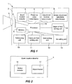
- FIG. 1 shows a schematic view of a camera 1 according to an embodiment of the present invention.
- the camera 1 may e.g. be a digital network video camera. Further, the camera 1 may be a stationary camera or a camera having pan/tilt functionality. In order to facilitate the understanding of the invention, standard features of a camera not being relevant for the present invention are not described.
- the camera 1 comprises a housing 2, a lens 3, an image sensor 4, an event location detector 5, a presence value determinator 6, an adjustment location determinator 7 and an image adjustment parameter determinator 8, a memory 9, a refocusing unit 10, an exposure time setting unit 11, a gain setting unit 12, an iris setting unit 13 a depth of filed setting unit 14 and a processor 15.
- the processor 15 is arranged to process and/or pass on data being generated by any of the other components of the camera 1.
- the lens 3 and the image sensor 4 are arranged to capture images representing an image view and send the images further to the event location detector 5.
- the image sensor 4 may for example be a Charge Coupled Device (CCD), a CMOS-sensor or similar, for registering incident light.
- the image sensor 4 may be a sensor registering non visible light, such as a bolometer.
- the event location detector 5 in the camera 1 is arranged to receive image data corresponding to a plurality of images captured by the camera 1.
- the event location detector 5 analyzes the image data corresponding to said plurality of images and determines a presence of an event. In case of an event being present the event location detector 5 is also arranged to determine a location within the image view for each event. Moreover, the event location detector 5 is arranged to determine the type of event. Types of events are the presence of motion and/or the presence of an object of a specific type, such as a person, a vehicle, a face, a license plate etc.
- the event location detector 5 may be implemented as a motion detector 16, as an object tracker 17 or as a combination thereof.
- An embodiment of the event location detector 5 comprising both a motion detector 16 and an object tracker 17 is illustrated in figure 2 .
- the motion detector 16 is arranged for detecting and analyzing motion in an image view monitored by the camera 1. Presence of motion within the image view may be regarded as an event. Normally image data corresponding to a plurality of images in the form of a video sequence is analyzed in order to determine the presence of motion. Examples of methods of motion detection include analyzing spatial-temporal changes in an image volume of a video sequence.
- the object tracker 17 is arranged to detect a presence of an object of a specific type, such as a person, a vehicle, a face, a license plate etc.
- the object tracker 17 may be implemented by using methods for identifying an object based on analyzing visual features in the images captured by the camera 1. Different types of methods for pattern or feature detection may for example be used for object detection. When analyzing visual features instead of motion it does not matter if the object that is to be identified is in motion or stationary. Predefined types of objects having specific appearance that are detected may for example be people, vehicles, faces, license plates etc., i.e. any type of object that may be distinguished from other events using visual features. Combinations of the methods described above and other types of similar methods may also be used to improve the identification or recognition of the presence of events of different event types.
- the location of the detected event is a location within the image view of the camera 1.
- the event normally covers more than one location; hence a determined presence of an event will normally result in occurrence in more than one location.
- each location within a scene monitored by the camera is represented by a pixel in the camera's image view.
- each location within a scene monitored by the camera is represented by a location, e.g. a pixel in the camera's current image view (i.e. represented by a pixel coordinate within one of said plurality of images), together with a pan/tilt setting of the camera.
- a location within the image view monitored by the pan/tilt camera may be determined.
- the presence value determinator 6 is arranged to receive data from the event location detector 5.
- the data comprises said locations within the image view of the events and/or information regarding the type of event. Information regarding the event is for example if the event is presence of motion or if the event is a specific object, e.g. a face.
- the presence value determinator 6 is further arranged to analyze the data in order to determine a presence value for each of said locations within the image view.
- a presence value is formed to reflect a number of occurrences of events of the specific event type in one of said locations within the image view. Depending on the size of each location and the extent of an event, the event may occur in more than one location.
- the presence values may be represented in a 3D histogram or a frequency map.
- each bin, corresponding to a location, in the 3D histogram or the frequency map contains a value indicating how many times an event of the specific type has occurred at that specific location within the image view.
- presence values indicate locations where events of the specific type generally appear and also locations where events of the specific type generally not appear.
- the presence value determinator 6 receives data from the event location detector 5, the data comprises locations of the presence of cars. The presence value determinator 6 analyses the data in order to determine the number of occurrences of cars in each of the locations of the image view monitored by the camera 1. As the number of occurrences of cars increases in certain locations of the scene monitored by the camera the presence value within these locations also increases.
- a way of visually describing this is by plotting the number of occurrences for each location in a 3D histogram or a frequency map.
- the locations representing the road will most likely have the highest number of occurrences after having a fair number of events analyzed.
- Figure 3 illustrates a simple example of four images representing an image view having each four locations, for instance being four pixels.
- An event of a specific event type has been found in all four images.
- the event of the specific type originates from the same specific event in all four images. It is however realized that the event of the specific event type may originate from different specific events in the various images.
- As the four images are analyzed a corresponding presence value for each of the four locations are aggregated.
- the presence values may be represented as a 3D histogram or a frequency map.
- the presence values may also be represented as a mathematical expression, for instance a plane being a polynomial and where the presence value in each location being the value of this polynomial in the specific location.
- the presence value determinator 6 is arranged to dynamically update the presence value over time as more image data is captured.
- the updating may be triggered in various ways. According to one example the updating is triggered when a certain amount of image data has been captured. According to another example the updating is triggered by that a certain time period has lapsed since the last update.
- the update may for example be that the presence value determinator 6 is arranged to simply add data regarding events originating from newly captured and analyzed images to the already existing presence values. According to another example the presence value determinator 6 is arranged to update the presence value by deleting old events. According to a further embodiment data regarding events originating from newly captured and analyzed images are added to already existing presence values and data corresponding to old events are deleted from the presence values.
- the adjustment location determinator 7 is arranged to analyze the presence values for the locations of the image view in order to determine an adjustment location.
- the adjustment location is determined as one or more locations in the image view having a presence value above a threshold. Locations having a low occurrence of events, being below the threshold, will be regarded as less relevant whereas locations having a high occurrence of events, being above the threshold, will be regarded as relevant.
- the image adjustment parameter determinator 8 is arranged to determine an image adjustment parameter based on data from said adjustment location. Based on the received data, the image adjustment parameter determinator 8 determines if an action is to be taken in terms of changing an image adjustment parameter. Again, using the example with the road and cars above, the image adjustment parameter determinator 8 may find that the road is the most relevant area to monitor and will determine one or more image adjustment parameters to be used to optimize the monitoring of the road.
- the image adjustment parameter determinator 8 is arranged to change a setting of the camera itself, to change a parameter used in the processing of the image data captured by the camera or a combination thereof.
- a change in a setting of the camera may for example be a change in the refocusing unit 10, an exposure time setting unit 11, the gain setting unit 12, the iris setting unit 13 and/or the depth of field setting unit 14. This change will affect the images that are to be captured.
- a change in a parameter used in the processing of the image data captured by the camera may for example be a change in a parameter controlling a color scheme, a signal to noise ratio or a contrast.
- the image adjustment parameter determinator 8 is arranged to determine an image adjustment parameter being optimized for the relevant locations.
- the image adjustment parameter may be used to optimize the camera settings or the processing of image data for the locations of the image view monitored by a camera being regarded as relevant, i.e. where, based in history, the probability for an event to be present is highest. Accordingly, it will be possible to optimize the display of the scene for the locations where it is most probable that an event is being present in the future.
- the event location detector 5, the presence value determinator 6, the adjustment location determinator 7 and/or the image adjustment parameter determinator 8 may be implemented using hardware or software. If implemented in software, the software may be recorded on a computer-readable recording medium, e.g. the memory 9 of the camera 1, in order to be executed by the processor 15 of the camera 1.
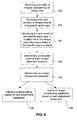
- Figure 4 illustrates a schematic flow chart according to an embodiment of a method for determining an image adjustment parameter according to the present invention.
- the method comprises the following steps: receiving 100 a plurality of images representing an image view; detecting 102 from said plurality of images events of a specific event type; Identifying 104 for each event of the specific event type, a location within the image view where said event of the specific type is present; determining 106 a presence value of each of said identified locations, a presence value is formed to reflect a number of occurrences of events of the specific event type in one of said identified locations; and determining 108 an image adjustment parameter based on data from an adjustment location within the image view, wherein the adjustment location is determined based on the presence value in each location of a plurality of locations within the image view.
- step 102 the received images are analyzed and events of a specific type are detected.
- An event may either be represented as a presence of motion or as an object having a specific appearance such as a person, a vehicle, a face, a license plate etc. Presence of motion is typically identified via a motion detection algorithm whereas presence of an object having a specific appearance is typically identified via an object tracking algorithm.
- step 104 identifying for each event of the specific event type, a location within the image view where said event of the specific type is present locations within an image view monitored by a camera being arranged to capture the plurality of images is determined.
- the event may cover more than one location; hence a determined presence of an event will normally result in a presence value in more than one location.
- the location of each identified event may be determined as the coordinates of the pixels in the image/images containing the event. This is a typically situation when said plurality of images are captured by a stationary camera.
- each event is typically described as a location within the coordinate system of the image containing the event combined with the pan/tilt setting of the camera. In this manner the location within the image view covered by the pan/tilt camera may be deduced.
- step 106 information from steps 102 and 104 is analyzed and a presence value in each of said locations of the image view is determined.
- the presence values indicate locations where events of the specific type generally appear and also locations where events of the specific type generally not appear.
- the step 106 of determining the presence value of each of said identified locations comprises aggregating the number of occurrences of events of the specific event type in each of said identified locations.
- the image adjustment parameter is determined based on data from an adjustment location within the image view.
- the image adjustment parameter may be used to adjust 110a a camera setting on a camera used to capture the plurality of images, to adjust 110b a parameter used in the processing of the image data or a combination thereof.
- An adjustment in a camera setting may for example be an adjustment affecting the focusing, exposure time, gain, iris, depth of field, etc of the camera. This adjustment will affect the images that are to be captured.
- An adjustment in a parameter used in the processing of the image data captured by the camera may for example be an adjustment in a parameter controlling the color scheme, the signal to noise ratio, the contract etc. This adjustment will affect new images to be processed.
- the image adjustment parameter may even be used to reprocess images that are already processed.
- the presence value is updated when further events of that specific type have been identified.
- the updating may be made in various ways; according to one embodiment the updating is made on a timely basis. That is, first a further plurality of images is collected during a predetermined time period, and secondly it is checked whether or not each of the further plurality of images contains an event of the specific type, and thirdly if so a location of said event of the specific type is determined. Next the presence values of the locations in the image view are updated with this newly gathered information regarding further events. Thereafter, the image adjustment parameter is updated based on said updated presence values. Alternatively the updating is made "on the fly", i.e. the images are analyzed and the presence values are updated as the images are being captured.
- the step of determining the presence value of said identified location comprises providing an existing presence value of each of said identified locations, and aggregating the existing presence value of each of said identified locations and a new presence value reflecting the number of further occurrences of the detected events of the specific event type in said identified location. This is an example on how to update already present presence values.
- the invention is applicable both for digital and analogue cameras.
- digital image processing is carried out within the camera and the digital signal is then converted to an analogue signal before leaving the camera.
- an image A/D converter connected to an analogue camera, a simpler analogue camera may be used.
- the camera 1 may be connected to a network, be a standalone camera or be connected within a system in other ways.
- the plurality of images may be either still or moving images or a combination thereof.
- the invention does not need to be implemented in a camera, it may instead be implemented in a camera system comprising a camera and a processing unit.
- the camera is connected to the processing unit, e.g. via a network.
- the camera is arranged to capture a plurality of images making up said image data and the processing unit is arranged to process the image data.
- the processing unit comprises said event location detector 5, said presence value determinator 6, said adjustment location determinator 7 and said image adjustment parameter determiniator 8.
- the processing unit may be arranged to send an image adjustment parameter in the form of a modified camera setting back to the camera or it may determine an image adjustment parameter being an image processing setting used within the processing unit or elsewhere.
- a plurality of cameras may be connected to the processing unit, wherein the processing unit is arranged to process the images captured by each one of the plurality of cameras.
Landscapes
- Engineering & Computer Science (AREA)
- Multimedia (AREA)
- Signal Processing (AREA)
- Physics & Mathematics (AREA)
- General Physics & Mathematics (AREA)
- Theoretical Computer Science (AREA)
- Computer Vision & Pattern Recognition (AREA)
- Software Systems (AREA)
- Studio Devices (AREA)
- Image Analysis (AREA)
- Exposure Control For Cameras (AREA)
Claims (9)
- Verfahren zum Bestimmen eines Teils einer Bildansicht, die zu verwenden ist, wenn ein Bildanpassungsparameter einer Kamera, wie etwa eine Kameraeinstellung und/oder eine Bildbearbeitungseinstellung, bestimmt wird, umfassend folgende Schritte:Empfangen (100) einer Vielzahl von Bildern in Form einer Videosequenz, die eine Bildansicht darstellt, die von der Kamera überwacht wird,Erkennen (102) aus der Bildervielzahl von Ereignissen eines spezifischen Ereignistyps, wobei die Ereignisse eines spezifischen Ereignistyps das Vorliegen einer Bewegung und/oder das Vorliegen eines Objekts, das ein spezifisches Aussehen aufweist, sind,gekennzeichnet durchIdentifizieren (104) für jedes Ereignis des spezifischen Ereignistyps der Position(en) innerhalb der Bildansicht, in der das Ereignis des spezifischen Typs vorliegt, wobei bei einer stationären Kamera die Position in der Bildansicht durch eine Pixelkoordinate in dem Bild oder den Bildern, das bzw. die das Ereignis enthält bzw. enthalten, dargestellt ist, und im Fall einer Kamera, die über Schwenk- und/oder Neigungsfähigkeiten verfügt, die Position innerhalb der Bildansicht durch eine Pixelkoordinate innerhalb eines der Vielzahl von Bildern zusammen mit der Schwenk-/Neigungseinstellung der Kamera dargestellt ist,Bestimmen (106) eines Präsenzwertes jeder der identifizierten Positionen, wobei ein Präsenzwert gebildet wird, um eine Auftrittsanzahl von Ereignissen des spezifischen Ereignistyps in einer der identifizierten Positionen wiederzugeben, undBestimmen des Teils der Bildansicht als eine oder mehrere der identifizierten Positionen in der Bildansicht, die einen Präsenzwert über einer Schwelle aufweist.
- Verfahren nach Anspruch 1, wobei der Schritt (106) des Bestimmens des Präsenzwertes der identifizierten Position Folgendes umfasst:Bereitstellen eines existierenden Präsenzwertes jeder der identifizierten Positionen, undZusammenfassen des existierenden Präsenzwertes jeder der identifizierten Positionen und eines neuen Präsenzwertes, der die weitere Auftrittsanzahl der erkannten Ereignisse des spezifischen Ereignistyps in der identifizierten Position wiedergibt.
- Verfahren nach einem der Ansprüche 1 und 2, ferner umfassend das Anpassen (110b) der Bearbeitung von Bilddaten unter Verwendung des Bildanpassungsparameters.
- Verfahren nach einem der Ansprüche 1 und 2, wobei die Bilddaten von einer Kamera aufgenommen werden, und wobei das Verfahren ferner das Anpassen (110a) einer Kameraeinstellung der Kamera unter Verwendung des Bildanpassungsparameters umfasst.
- Kamera (1), die angeordnet ist, um eine Vielzahl von Bildern in der Form einer Videosequenz aufzunehmen, die eine Bildansicht darstellt, die von der Kamera überwacht wird, und um einen Teil der Bildansicht zu bestimmen, der zu verwenden ist, wenn ein Bildanpassungsparameter, wie etwa eine Kameraeinstellung und/oder eine Bildbearbeitungseinstellung, bestimmt wird, umfassend:einen Ereignispositionsdetektor (5), der angeordnet ist, um aus der Vielzahl von Bildern Ereignisse eines spezifischen Ereignistyps zu erkennen, wobei die Ereignisse des spezifischen Ereignistyps das Vorliegen einer Bewegung und/oder das Vorliegen eines Objekts, das ein spezifisches Aussehen aufweist, sind,dadurch gekennzeichnet, dassder Ereignispositionsdetektor ferner angeordnet ist, um die Position(en) innerhalb der Bildansicht zu erkennen, in der das Ereignis des spezifischen Typs vorliegt, wobei, falls die Kamera eine stationäre Kamera ist, die Position in der Bildansicht durch eine Pixelkoordinate in dem Bild oder den Bildern, das bzw. die das Ereignis enthält bzw. enthalten, dargestellt ist, und falls die Kamera über Schwenk- und/oder Neigungsfähigkeiten verfügt, die Position innerhalb der Bildansicht durch eine Pixelkoordinate innerhalb eines der Vielzahl von Bildern zusammen mit der Schwenk-/Neigungseinstellung der Kamera dargestellt ist,eine Präsenzwert-Bestimmungsvorrichtung (6), die angeordnet ist, um einen Präsenzwert jeder der identifizierten Positionen innerhalb der Bildansicht zu bestimmen, wobei ein Präsenzwert gebildet wird, um eine Auftrittsanzahl von Ereignissen des spezifischen Ereignistyps in einer der identifizierten Positionen innerhalb der Bildansicht wiederzugeben,eine Anpassungspositions-Bestimmungsvorrichtung (7), die angeordnet ist, um den Teil der Bildansicht als eine oder mehrere der identifizierten Positionen in der Bildansicht, die einen Präsenzwert über einer Schwelle aufweist, zu bestimmen. undeine Bildanpassungsparameter-Bestimmungsvorrichtung (8), die angeordnet ist, um Daten von der Anpassungsposition zu empfangen.
- Kamera (1) nach Anspruch 5, wobei der Ereignispositionsdetektor (5), die Präsenzwert-Bestimmungsvorrichtung (6), die Anpassungspositions-Bestimmungsvorrichtung (7) und/oder die Bildanpassungsparameter-Bestimmungsvorrichtung (8) anhand von Software-Code, der in einem Speicher (9) der Kamera gespeichert ist und anhand eines Prozessors (15) in der Kamera (1) ausgeführt wird, anhand von Hardware-Einheiten, die in der Kamera (1) vorliegen, oder anhand einer Kombination davon umgesetzt sind.
- Kamera (1) nach Anspruch 5 oder 6, ferner umfassend eine Neufokussierungseinheit (10), eine Belichtungszeit-Einstellungseinheit (11), eine Verstärkungs-Einstellungseinheit (12), eine Blenden-Einstellungseinheit (13) und/oder eine Schärfentiefen-Einstellungseinheit (14), wobei der Bildanpassungsparameter verwendet wird, um die Neufokussierungseinheit (10), die Belichtungszeit-Einstellungseinheit (11), die Verstärkungs-Einstellungseinheit (12), die Blenden-Einstellungseinheit (13) und/oder die Schärfentiefen-Einstellungseinheit (14) der Kamera (1) anzupassen.
- Kamera (1) nach einem der Ansprüche 5 bis 7, wobei der Ereignispositionsdetektor (5) als Bewegungsdetektor (16), als Objektverfolgungsvorrichtung (17) oder als Kombination davon umgesetzt ist.
- Computerlesbares Aufzeichnungsmedium, auf dem ein Programm aufgezeichnet ist, um das Verfahren nach einem der Ansprüche 1 bis 4 umzusetzen, wenn es auf einer Vorrichtung mit Bearbeitungsfähigkeiten ausgeführt wird.
Priority Applications (8)
| Application Number | Priority Date | Filing Date | Title |
|---|---|---|---|
| EP11174491.8A EP2549738B1 (de) | 2011-07-19 | 2011-07-19 | Verfahren und Kamera zur Bestimmung einer Bildeinstellungsausgabe |
| TW101124534A TWI554099B (zh) | 2011-07-19 | 2012-07-06 | 用於決定一影像調整參數之方法及攝影機 |
| US13/543,039 US9635237B2 (en) | 2011-07-19 | 2012-07-06 | Method and camera for determining an image adjustment parameter |
| JP2012154334A JP5400195B2 (ja) | 2011-07-19 | 2012-07-10 | 画像調整パラメータを決定するための方法およびカメラ |
| CN201210241550.3A CN102891960B (zh) | 2011-07-19 | 2012-07-12 | 用于确定图像调整参数的方法和相机 |
| KR1020120078871A KR101663752B1 (ko) | 2011-07-19 | 2012-07-19 | 화상 조정 파라미터를 결정하기 위한 방법 및 카메라 |
| KR1020160125740A KR101826897B1 (ko) | 2011-07-19 | 2016-09-29 | 화상 조정 파라미터를 결정하기 위한 방법 및 카메라 |
| US15/483,579 US10070053B2 (en) | 2011-07-19 | 2017-04-10 | Method and camera for determining an image adjustment parameter |
Applications Claiming Priority (1)
| Application Number | Priority Date | Filing Date | Title |
|---|---|---|---|
| EP11174491.8A EP2549738B1 (de) | 2011-07-19 | 2011-07-19 | Verfahren und Kamera zur Bestimmung einer Bildeinstellungsausgabe |
Publications (2)
| Publication Number | Publication Date |
|---|---|
| EP2549738A1 EP2549738A1 (de) | 2013-01-23 |
| EP2549738B1 true EP2549738B1 (de) | 2013-08-28 |
Family
ID=44367040
Family Applications (1)
| Application Number | Title | Priority Date | Filing Date |
|---|---|---|---|
| EP11174491.8A Active EP2549738B1 (de) | 2011-07-19 | 2011-07-19 | Verfahren und Kamera zur Bestimmung einer Bildeinstellungsausgabe |
Country Status (6)
| Country | Link |
|---|---|
| US (2) | US9635237B2 (de) |
| EP (1) | EP2549738B1 (de) |
| JP (1) | JP5400195B2 (de) |
| KR (2) | KR101663752B1 (de) |
| CN (1) | CN102891960B (de) |
| TW (1) | TWI554099B (de) |
Families Citing this family (21)
| Publication number | Priority date | Publication date | Assignee | Title |
|---|---|---|---|---|
| EP2549738B1 (de) * | 2011-07-19 | 2013-08-28 | Axis AB | Verfahren und Kamera zur Bestimmung einer Bildeinstellungsausgabe |
| US20140093174A1 (en) * | 2012-09-28 | 2014-04-03 | Canon Kabushiki Kaisha | Systems and methods for image management |
| KR102327779B1 (ko) * | 2014-02-21 | 2021-11-18 | 삼성전자주식회사 | 이미지 처리 방법 및 장치 |
| WO2015159323A1 (en) * | 2014-04-17 | 2015-10-22 | Sony Corporation | Depth assisted scene recognition for a camera |
| TWI518437B (zh) * | 2014-05-12 | 2016-01-21 | 晶睿通訊股份有限公司 | 動態對焦調整系統及其動態對焦調整方法 |
| US9661319B2 (en) * | 2014-05-21 | 2017-05-23 | GM Global Technology Operations LLC | Method and apparatus for automatic calibration in surrounding view systems |
| DE102016122485A1 (de) * | 2016-11-22 | 2018-05-24 | Jungheinrich Aktiengesellschaft | Verfahren zur Bereitstellung der Positionen von Lagerplätzen in einem Lager und Flurförderzeug |
| EP3340609B1 (de) | 2016-12-22 | 2024-03-27 | Samsung Electronics Co., Ltd. | Vorrichtung und verfahren zur bildverarbeitung |
| KR102407815B1 (ko) * | 2016-12-22 | 2022-06-13 | 삼성전자주식회사 | 영상 처리 장치 및 방법 |
| CN108664847B (zh) * | 2017-03-29 | 2021-10-22 | 华为技术有限公司 | 一种对象识别方法、设备和系统 |
| US10269140B2 (en) | 2017-05-04 | 2019-04-23 | Second Spectrum, Inc. | Method and apparatus for automatic intrinsic camera calibration using images of a planar calibration pattern |
| KR102437456B1 (ko) * | 2017-11-14 | 2022-08-26 | 애플 인크. | 이벤트 카메라-기반 변형가능 물체 추적 |
| EP3827582A4 (de) * | 2018-08-14 | 2021-07-21 | Huawei Technologies Co., Ltd. | Bildverarbeitungsvorrichtung und verfahren zur merkmalsextraktion |
| EP3667557B1 (de) * | 2018-12-13 | 2021-06-16 | Axis AB | Verfahren und vorrichtung zur verfolgung eines objekts |
| JP7368822B2 (ja) * | 2019-05-31 | 2023-10-25 | i-PRO株式会社 | カメラパラメータ設定システムおよびカメラパラメータ設定方法 |
| TWI716921B (zh) | 2019-06-28 | 2021-01-21 | 華碩電腦股份有限公司 | 偵測裝置、偵測系統及偵測方法 |
| CN110769239B (zh) * | 2019-10-26 | 2020-08-18 | 岳阳县辉通物联网科技有限公司 | 基于场景识别的参数大数据设定装置 |
| CN112770081B (zh) * | 2019-11-01 | 2023-05-02 | 杭州海康威视数字技术股份有限公司 | 监控设备的参数调整方法、装置、电子设备及存储介质 |
| CN111179354A (zh) * | 2019-12-16 | 2020-05-19 | 中国辐射防护研究院 | 一种实验标定光场相机重聚焦距离和对应α值的方法 |
| EP3979618A1 (de) * | 2020-10-01 | 2022-04-06 | Axis AB | Verfahren zum konfigurieren einer kamera |
| CN114913470B (zh) * | 2022-07-11 | 2022-10-28 | 浙江大华技术股份有限公司 | 一种事件检测方法及装置 |
Family Cites Families (21)
| Publication number | Priority date | Publication date | Assignee | Title |
|---|---|---|---|---|
| KR100213055B1 (ko) * | 1996-07-27 | 1999-08-02 | 윤종용 | 감시용 시스템에서의 기록 매체 절약형 기록방법 |
| US6137580A (en) | 1998-09-22 | 2000-10-24 | Creo Srl | Autofocus system |
| US7280753B2 (en) * | 2003-09-03 | 2007-10-09 | Canon Kabushiki Kaisha | Display apparatus, image processing apparatus, and image processing system |
| US7148912B2 (en) * | 2003-11-17 | 2006-12-12 | Vidient Systems, Inc. | Video surveillance system in which trajectory hypothesis spawning allows for trajectory splitting and/or merging |
| KR101069181B1 (ko) | 2004-08-31 | 2011-09-30 | 엘지전자 주식회사 | 감시용 디지털 비디오 레코더에서의 모션 검출 영역 자동설정장치 및 방법 |
| CN101095078B (zh) | 2004-12-29 | 2010-04-28 | 诺基亚公司 | 数字成像的曝光 |
| JP4324170B2 (ja) * | 2005-03-17 | 2009-09-02 | キヤノン株式会社 | 撮像装置およびディスプレイの制御方法 |
| JP4218670B2 (ja) * | 2005-09-27 | 2009-02-04 | オムロン株式会社 | 前方撮影装置 |
| JP5044321B2 (ja) * | 2006-09-13 | 2012-10-10 | 株式会社リコー | 撮像装置および被写体検出方法 |
| TWI335181B (en) * | 2006-12-13 | 2010-12-21 | Univ Chung Yuan Christian | Human behavior event detection system, method and device |
| JP4902562B2 (ja) * | 2007-02-07 | 2012-03-21 | パナソニック株式会社 | 撮像装置、画像処理装置、制御方法およびプログラム |
| JP4254873B2 (ja) * | 2007-02-16 | 2009-04-15 | ソニー株式会社 | 画像処理装置及び画像処理方法、撮像装置、並びにコンピュータ・プログラム |
| TW200842733A (en) * | 2007-04-17 | 2008-11-01 | Univ Nat Chiao Tung | Object image detection method |
| JP2009059073A (ja) * | 2007-08-30 | 2009-03-19 | Toshiba Corp | 撮影装置、撮影方法、人物認識装置および人物認識方法 |
| JP4518131B2 (ja) * | 2007-10-05 | 2010-08-04 | 富士フイルム株式会社 | 撮像方法及び装置 |
| JP2010021598A (ja) * | 2008-07-08 | 2010-01-28 | Victor Co Of Japan Ltd | 撮像装置および撮像方法 |
| JP2010021943A (ja) | 2008-07-14 | 2010-01-28 | Sanyo Electric Co Ltd | 撮像装置 |
| US8345101B2 (en) | 2008-10-31 | 2013-01-01 | International Business Machines Corporation | Automatically calibrating regions of interest for video surveillance |
| JP5419585B2 (ja) * | 2009-08-04 | 2014-02-19 | キヤノン株式会社 | 画像処理装置および画像処理方法並びにプログラム |
| US8594482B2 (en) * | 2010-05-13 | 2013-11-26 | International Business Machines Corporation | Auditing video analytics through essence generation |
| EP2549738B1 (de) * | 2011-07-19 | 2013-08-28 | Axis AB | Verfahren und Kamera zur Bestimmung einer Bildeinstellungsausgabe |
-
2011
- 2011-07-19 EP EP11174491.8A patent/EP2549738B1/de active Active
-
2012
- 2012-07-06 US US13/543,039 patent/US9635237B2/en active Active
- 2012-07-06 TW TW101124534A patent/TWI554099B/zh active
- 2012-07-10 JP JP2012154334A patent/JP5400195B2/ja active Active
- 2012-07-12 CN CN201210241550.3A patent/CN102891960B/zh active Active
- 2012-07-19 KR KR1020120078871A patent/KR101663752B1/ko active IP Right Grant
-
2016
- 2016-09-29 KR KR1020160125740A patent/KR101826897B1/ko active IP Right Grant
-
2017
- 2017-04-10 US US15/483,579 patent/US10070053B2/en active Active
Also Published As
| Publication number | Publication date |
|---|---|
| TWI554099B (zh) | 2016-10-11 |
| KR20130010875A (ko) | 2013-01-29 |
| TW201313012A (zh) | 2013-03-16 |
| EP2549738A1 (de) | 2013-01-23 |
| KR20160118183A (ko) | 2016-10-11 |
| JP5400195B2 (ja) | 2014-01-29 |
| JP2013031167A (ja) | 2013-02-07 |
| US10070053B2 (en) | 2018-09-04 |
| US20130021477A1 (en) | 2013-01-24 |
| CN102891960A (zh) | 2013-01-23 |
| US9635237B2 (en) | 2017-04-25 |
| KR101663752B1 (ko) | 2016-10-07 |
| KR101826897B1 (ko) | 2018-02-08 |
| CN102891960B (zh) | 2017-05-17 |
| US20170214850A1 (en) | 2017-07-27 |
Similar Documents
| Publication | Publication Date | Title |
|---|---|---|
| US10070053B2 (en) | Method and camera for determining an image adjustment parameter | |
| US10204275B2 (en) | Image monitoring system and surveillance camera | |
| CN107258077B (zh) | 用于连续自动聚焦(caf)的系统和方法 | |
| CN107016367B (zh) | 一种跟踪控制方法及跟踪控制系统 | |
| US8068639B2 (en) | Image pickup apparatus, control method therefor, and computer program for detecting image blur according to movement speed and change in size of face area | |
| US9823331B2 (en) | Object detecting apparatus, image capturing apparatus, method for controlling object detecting apparatus, and storage medium | |
| EP2608529B1 (de) | Kamera und Verfahren zur Optimierung der Belichtung eines Einzelbildes in einer Sequenz von Einzelbildern, die eine Szene auf Grundlage des Bewegungsgrads in der Szene erfassen | |
| KR20150032630A (ko) | 촬상 시스템에 있어서의 제어방법, 제어장치 및 컴퓨터 판독 가능한 기억매체 | |
| US20190230269A1 (en) | Monitoring camera, method of controlling monitoring camera, and non-transitory computer-readable storage medium | |
| JP6292540B2 (ja) | 情報処理システム、情報処理方法及びプログラム | |
| KR20090043416A (ko) | 카메라 이동 영향을 검출하고 억제하는 감시 카메라 장치및 그 제어 방법 | |
| US20160212410A1 (en) | Depth triggered event feature | |
| CN115760912A (zh) | 运动目标跟踪方法、装置、设备及计算机可读存储介质 | |
| CN112132863A (zh) | 一种高空抛物检测流程及分析方法 | |
| KR20190026625A (ko) | 영상 표시 방법 및 컴퓨터 프로그램, 그 기록매체 | |
| CN112884805A (zh) | 一种跨尺度自适应映射的光场成像方法 | |
| JP7250433B2 (ja) | 撮像装置、制御方法及びプログラム | |
| CN117280708A (zh) | 利用基于ai的对象识别的监控摄像机的快门值调节 | |
| JP5599228B2 (ja) | 繁忙検知システム及び繁忙検知プログラム | |
| US11908197B2 (en) | Information processing apparatus, information processing method, and storage medium | |
| CN117835053B (zh) | 宽动态模式的切换方法和装置 | |
| WO2020095790A1 (ja) | 被写体検知装置、システム、方法および記録媒体 | |
| JP5842647B2 (ja) | 探知装置 | |
| CN117857911A (zh) | 拍摄方法、装置、电子设备及存储介质 | |
| CN117274910A (zh) | 人员滞留监测方法、装置、电子设备及存储介质 |
Legal Events
| Date | Code | Title | Description |
|---|---|---|---|
| PUAI | Public reference made under article 153(3) epc to a published international application that has entered the european phase |
Free format text: ORIGINAL CODE: 0009012 |
|
| 17P | Request for examination filed |
Effective date: 20111115 |
|
| AK | Designated contracting states |
Kind code of ref document: A1 Designated state(s): AL AT BE BG CH CY CZ DE DK EE ES FI FR GB GR HR HU IE IS IT LI LT LU LV MC MK MT NL NO PL PT RO RS SE SI SK SM TR |
|
| AX | Request for extension of the european patent |
Extension state: BA ME |
|
| GRAP | Despatch of communication of intention to grant a patent |
Free format text: ORIGINAL CODE: EPIDOSNIGR1 |
|
| INTG | Intention to grant announced |
Effective date: 20130402 |
|
| GRAS | Grant fee paid |
Free format text: ORIGINAL CODE: EPIDOSNIGR3 |
|
| GRAA | (expected) grant |
Free format text: ORIGINAL CODE: 0009210 |
|
| AK | Designated contracting states |
Kind code of ref document: B1 Designated state(s): AL AT BE BG CH CY CZ DE DK EE ES FI FR GB GR HR HU IE IS IT LI LT LU LV MC MK MT NL NO PL PT RO RS SE SI SK SM TR |
|
| REG | Reference to a national code |
Ref country code: GB Ref legal event code: FG4D |
|
| REG | Reference to a national code |
Ref country code: CH Ref legal event code: EP |
|
| REG | Reference to a national code |
Ref country code: AT Ref legal event code: REF Ref document number: 629889 Country of ref document: AT Kind code of ref document: T Effective date: 20130915 |
|
| REG | Reference to a national code |
Ref country code: IE Ref legal event code: FG4D |
|
| REG | Reference to a national code |
Ref country code: DE Ref legal event code: R096 Ref document number: 602011002808 Country of ref document: DE Effective date: 20131024 |
|
| REG | Reference to a national code |
Ref country code: SE Ref legal event code: TRGR |
|
| REG | Reference to a national code |
Ref country code: AT Ref legal event code: MK05 Ref document number: 629889 Country of ref document: AT Kind code of ref document: T Effective date: 20130828 |
|
| REG | Reference to a national code |
Ref country code: LT Ref legal event code: MG4D |
|
| REG | Reference to a national code |
Ref country code: NL Ref legal event code: VDEP Effective date: 20130828 |
|
| PG25 | Lapsed in a contracting state [announced via postgrant information from national office to epo] |
Ref country code: NO Free format text: LAPSE BECAUSE OF FAILURE TO SUBMIT A TRANSLATION OF THE DESCRIPTION OR TO PAY THE FEE WITHIN THE PRESCRIBED TIME-LIMIT Effective date: 20131128 Ref country code: CY Free format text: LAPSE BECAUSE OF FAILURE TO SUBMIT A TRANSLATION OF THE DESCRIPTION OR TO PAY THE FEE WITHIN THE PRESCRIBED TIME-LIMIT Effective date: 20130918 Ref country code: PT Free format text: LAPSE BECAUSE OF FAILURE TO SUBMIT A TRANSLATION OF THE DESCRIPTION OR TO PAY THE FEE WITHIN THE PRESCRIBED TIME-LIMIT Effective date: 20131230 Ref country code: HR Free format text: LAPSE BECAUSE OF FAILURE TO SUBMIT A TRANSLATION OF THE DESCRIPTION OR TO PAY THE FEE WITHIN THE PRESCRIBED TIME-LIMIT Effective date: 20130828 Ref country code: LT Free format text: LAPSE BECAUSE OF FAILURE TO SUBMIT A TRANSLATION OF THE DESCRIPTION OR TO PAY THE FEE WITHIN THE PRESCRIBED TIME-LIMIT Effective date: 20130828 Ref country code: AT Free format text: LAPSE BECAUSE OF FAILURE TO SUBMIT A TRANSLATION OF THE DESCRIPTION OR TO PAY THE FEE WITHIN THE PRESCRIBED TIME-LIMIT Effective date: 20130828 Ref country code: IS Free format text: LAPSE BECAUSE OF FAILURE TO SUBMIT A TRANSLATION OF THE DESCRIPTION OR TO PAY THE FEE WITHIN THE PRESCRIBED TIME-LIMIT Effective date: 20131228 |
|
| REG | Reference to a national code |
Ref country code: NL Ref legal event code: VDEP Effective date: 20130828 |
|
| PG25 | Lapsed in a contracting state [announced via postgrant information from national office to epo] |
Ref country code: PL Free format text: LAPSE BECAUSE OF FAILURE TO SUBMIT A TRANSLATION OF THE DESCRIPTION OR TO PAY THE FEE WITHIN THE PRESCRIBED TIME-LIMIT Effective date: 20130828 Ref country code: LV Free format text: LAPSE BECAUSE OF FAILURE TO SUBMIT A TRANSLATION OF THE DESCRIPTION OR TO PAY THE FEE WITHIN THE PRESCRIBED TIME-LIMIT Effective date: 20130828 Ref country code: BE Free format text: LAPSE BECAUSE OF FAILURE TO SUBMIT A TRANSLATION OF THE DESCRIPTION OR TO PAY THE FEE WITHIN THE PRESCRIBED TIME-LIMIT Effective date: 20130828 Ref country code: GR Free format text: LAPSE BECAUSE OF FAILURE TO SUBMIT A TRANSLATION OF THE DESCRIPTION OR TO PAY THE FEE WITHIN THE PRESCRIBED TIME-LIMIT Effective date: 20131129 Ref country code: FI Free format text: LAPSE BECAUSE OF FAILURE TO SUBMIT A TRANSLATION OF THE DESCRIPTION OR TO PAY THE FEE WITHIN THE PRESCRIBED TIME-LIMIT Effective date: 20130828 |
|
| PG25 | Lapsed in a contracting state [announced via postgrant information from national office to epo] |
Ref country code: CY Free format text: LAPSE BECAUSE OF FAILURE TO SUBMIT A TRANSLATION OF THE DESCRIPTION OR TO PAY THE FEE WITHIN THE PRESCRIBED TIME-LIMIT Effective date: 20130828 |
|
| PG25 | Lapsed in a contracting state [announced via postgrant information from national office to epo] |
Ref country code: NL Free format text: LAPSE BECAUSE OF FAILURE TO SUBMIT A TRANSLATION OF THE DESCRIPTION OR TO PAY THE FEE WITHIN THE PRESCRIBED TIME-LIMIT Effective date: 20130828 Ref country code: DK Free format text: LAPSE BECAUSE OF FAILURE TO SUBMIT A TRANSLATION OF THE DESCRIPTION OR TO PAY THE FEE WITHIN THE PRESCRIBED TIME-LIMIT Effective date: 20130828 Ref country code: EE Free format text: LAPSE BECAUSE OF FAILURE TO SUBMIT A TRANSLATION OF THE DESCRIPTION OR TO PAY THE FEE WITHIN THE PRESCRIBED TIME-LIMIT Effective date: 20130828 Ref country code: SK Free format text: LAPSE BECAUSE OF FAILURE TO SUBMIT A TRANSLATION OF THE DESCRIPTION OR TO PAY THE FEE WITHIN THE PRESCRIBED TIME-LIMIT Effective date: 20130828 Ref country code: RO Free format text: LAPSE BECAUSE OF FAILURE TO SUBMIT A TRANSLATION OF THE DESCRIPTION OR TO PAY THE FEE WITHIN THE PRESCRIBED TIME-LIMIT Effective date: 20130828 Ref country code: CZ Free format text: LAPSE BECAUSE OF FAILURE TO SUBMIT A TRANSLATION OF THE DESCRIPTION OR TO PAY THE FEE WITHIN THE PRESCRIBED TIME-LIMIT Effective date: 20130828 |
|
| PG25 | Lapsed in a contracting state [announced via postgrant information from national office to epo] |
Ref country code: IT Free format text: LAPSE BECAUSE OF FAILURE TO SUBMIT A TRANSLATION OF THE DESCRIPTION OR TO PAY THE FEE WITHIN THE PRESCRIBED TIME-LIMIT Effective date: 20130828 Ref country code: ES Free format text: LAPSE BECAUSE OF FAILURE TO SUBMIT A TRANSLATION OF THE DESCRIPTION OR TO PAY THE FEE WITHIN THE PRESCRIBED TIME-LIMIT Effective date: 20130828 |
|
| REG | Reference to a national code |
Ref country code: DE Ref legal event code: R097 Ref document number: 602011002808 Country of ref document: DE |
|
| PLBE | No opposition filed within time limit |
Free format text: ORIGINAL CODE: 0009261 |
|
| STAA | Information on the status of an ep patent application or granted ep patent |
Free format text: STATUS: NO OPPOSITION FILED WITHIN TIME LIMIT |
|
| 26N | No opposition filed |
Effective date: 20140530 |
|
| REG | Reference to a national code |
Ref country code: DE Ref legal event code: R097 Ref document number: 602011002808 Country of ref document: DE Effective date: 20140530 |
|
| PG25 | Lapsed in a contracting state [announced via postgrant information from national office to epo] |
Ref country code: LU Free format text: LAPSE BECAUSE OF FAILURE TO SUBMIT A TRANSLATION OF THE DESCRIPTION OR TO PAY THE FEE WITHIN THE PRESCRIBED TIME-LIMIT Effective date: 20140719 |
|
| REG | Reference to a national code |
Ref country code: CH Ref legal event code: PL |
|
| REG | Reference to a national code |
Ref country code: IE Ref legal event code: MM4A |
|
| PG25 | Lapsed in a contracting state [announced via postgrant information from national office to epo] |
Ref country code: LI Free format text: LAPSE BECAUSE OF NON-PAYMENT OF DUE FEES Effective date: 20140731 Ref country code: CH Free format text: LAPSE BECAUSE OF NON-PAYMENT OF DUE FEES Effective date: 20140731 |
|
| PG25 | Lapsed in a contracting state [announced via postgrant information from national office to epo] |
Ref country code: IE Free format text: LAPSE BECAUSE OF NON-PAYMENT OF DUE FEES Effective date: 20140719 |
|
| PG25 | Lapsed in a contracting state [announced via postgrant information from national office to epo] |
Ref country code: SM Free format text: LAPSE BECAUSE OF FAILURE TO SUBMIT A TRANSLATION OF THE DESCRIPTION OR TO PAY THE FEE WITHIN THE PRESCRIBED TIME-LIMIT Effective date: 20130828 Ref country code: MC Free format text: LAPSE BECAUSE OF FAILURE TO SUBMIT A TRANSLATION OF THE DESCRIPTION OR TO PAY THE FEE WITHIN THE PRESCRIBED TIME-LIMIT Effective date: 20130828 |
|
| REG | Reference to a national code |
Ref country code: FR Ref legal event code: PLFP Year of fee payment: 6 |
|
| PG25 | Lapsed in a contracting state [announced via postgrant information from national office to epo] |
Ref country code: RS Free format text: LAPSE BECAUSE OF FAILURE TO SUBMIT A TRANSLATION OF THE DESCRIPTION OR TO PAY THE FEE WITHIN THE PRESCRIBED TIME-LIMIT Effective date: 20130828 Ref country code: BG Free format text: LAPSE BECAUSE OF FAILURE TO SUBMIT A TRANSLATION OF THE DESCRIPTION OR TO PAY THE FEE WITHIN THE PRESCRIBED TIME-LIMIT Effective date: 20130828 Ref country code: MT Free format text: LAPSE BECAUSE OF FAILURE TO SUBMIT A TRANSLATION OF THE DESCRIPTION OR TO PAY THE FEE WITHIN THE PRESCRIBED TIME-LIMIT Effective date: 20130828 |
|
| PG25 | Lapsed in a contracting state [announced via postgrant information from national office to epo] |
Ref country code: HU Free format text: LAPSE BECAUSE OF FAILURE TO SUBMIT A TRANSLATION OF THE DESCRIPTION OR TO PAY THE FEE WITHIN THE PRESCRIBED TIME-LIMIT; INVALID AB INITIO Effective date: 20110719 Ref country code: TR Free format text: LAPSE BECAUSE OF FAILURE TO SUBMIT A TRANSLATION OF THE DESCRIPTION OR TO PAY THE FEE WITHIN THE PRESCRIBED TIME-LIMIT Effective date: 20130828 Ref country code: SI Free format text: LAPSE BECAUSE OF FAILURE TO SUBMIT A TRANSLATION OF THE DESCRIPTION OR TO PAY THE FEE WITHIN THE PRESCRIBED TIME-LIMIT Effective date: 20130828 |
|
| REG | Reference to a national code |
Ref country code: FR Ref legal event code: PLFP Year of fee payment: 7 |
|
| REG | Reference to a national code |
Ref country code: FR Ref legal event code: PLFP Year of fee payment: 8 |
|
| PG25 | Lapsed in a contracting state [announced via postgrant information from national office to epo] |
Ref country code: MK Free format text: LAPSE BECAUSE OF FAILURE TO SUBMIT A TRANSLATION OF THE DESCRIPTION OR TO PAY THE FEE WITHIN THE PRESCRIBED TIME-LIMIT Effective date: 20130828 |
|
| PG25 | Lapsed in a contracting state [announced via postgrant information from national office to epo] |
Ref country code: AL Free format text: LAPSE BECAUSE OF FAILURE TO SUBMIT A TRANSLATION OF THE DESCRIPTION OR TO PAY THE FEE WITHIN THE PRESCRIBED TIME-LIMIT Effective date: 20130828 |
|
| REG | Reference to a national code |
Ref country code: DE Ref legal event code: R079 Ref document number: 602011002808 Country of ref document: DE Free format text: PREVIOUS MAIN CLASS: H04N0005232000 Ipc: H04N0023600000 |
|
| P01 | Opt-out of the competence of the unified patent court (upc) registered |
Effective date: 20230505 |
|
| PGFP | Annual fee paid to national office [announced via postgrant information from national office to epo] |
Ref country code: FR Payment date: 20230621 Year of fee payment: 13 |
|
| PGFP | Annual fee paid to national office [announced via postgrant information from national office to epo] |
Ref country code: SE Payment date: 20230622 Year of fee payment: 13 |
|
| PGFP | Annual fee paid to national office [announced via postgrant information from national office to epo] |
Ref country code: GB Payment date: 20230620 Year of fee payment: 13 |
|
| PGFP | Annual fee paid to national office [announced via postgrant information from national office to epo] |
Ref country code: DE Payment date: 20230620 Year of fee payment: 13 |